1. Introduction
In the water industry, sensor technology guarantees the collection of a large amount of information related to the infrastructure. Additionally, smart sensors, endowed with energy sources, data storage units and wireless transmission, can transfer the above-mentioned data to easy-to-access server units and make them available for analysis and processing.
In Water Distribution Networks (WDNs), sensor technology has been widely investigated for water pressure and quality monitoring, as well as for the selection of their optimal number and allocation [
1,
2].
Most of these implementations are powered by batteries, which require manual recharging. Despite the fact that the capacity of the new batteries, for given cost and size, has significantly increased in recent years, the request for new services and data types with very frequent transmission has also suggested the use of self-powered sensors that can provide continuous monitoring without the need for external energy sources. To this end, several applications employing energy harvesting technologies have been developed in the field of power generation through wind, solar, and chemical energies [
3]. Recently, self-powered sensors were designed for turbine flowmeters to also measure the water flow rate [
4].
However, the electric power generated by most of these applications is only sufficient to supply the energy required by the sensor and the data transmission, but is not large enough to control the monitored quantity via mechanical movements of the hosting device. For example, it is not possible to control the flow rate measured by the flow meter by means of a single device.
We propose a new self-powered device embedding flow rate measurement and control for water distribution networks. The new device is given by a nano-PRS cross-flow turbine with a special regulation mobile component referred to as slider. The device can either maximize the energy production and measure the flow rate with a small and limited head dissipation (passive mode) or control the flow rate with a higher head dissipation (active mode). The produced mean power, in the test case of a flow meter serving about 40 inhabitants, is about 100 W, which is much larger than the required amount, even in the case of frequent active modes. This allows the use of the proposed device as an energy provider for other sensors, including pressure, temperature, turbidity and other quality parameters.
2. A Self-Powered Multiparametric Sensor and Valve
The new device has been designed to measure pressure and flow rate, in addition to extracting a small amount of hydraulic energy from the pipe where it is installed in order to power itself. It is based on the Venturi effect occurring in the converging channel between the section of the hosting pipe and the first section of the nozzle of the microturbine. The resulting differential pressure Δp is directly related to the flow rate, and its range is guaranteed, even for small discharges, through the regulation of a mobile slider controlling the distance between the two walls of the nozzle orthogonal to the runner axis.
2.1. Power Generation
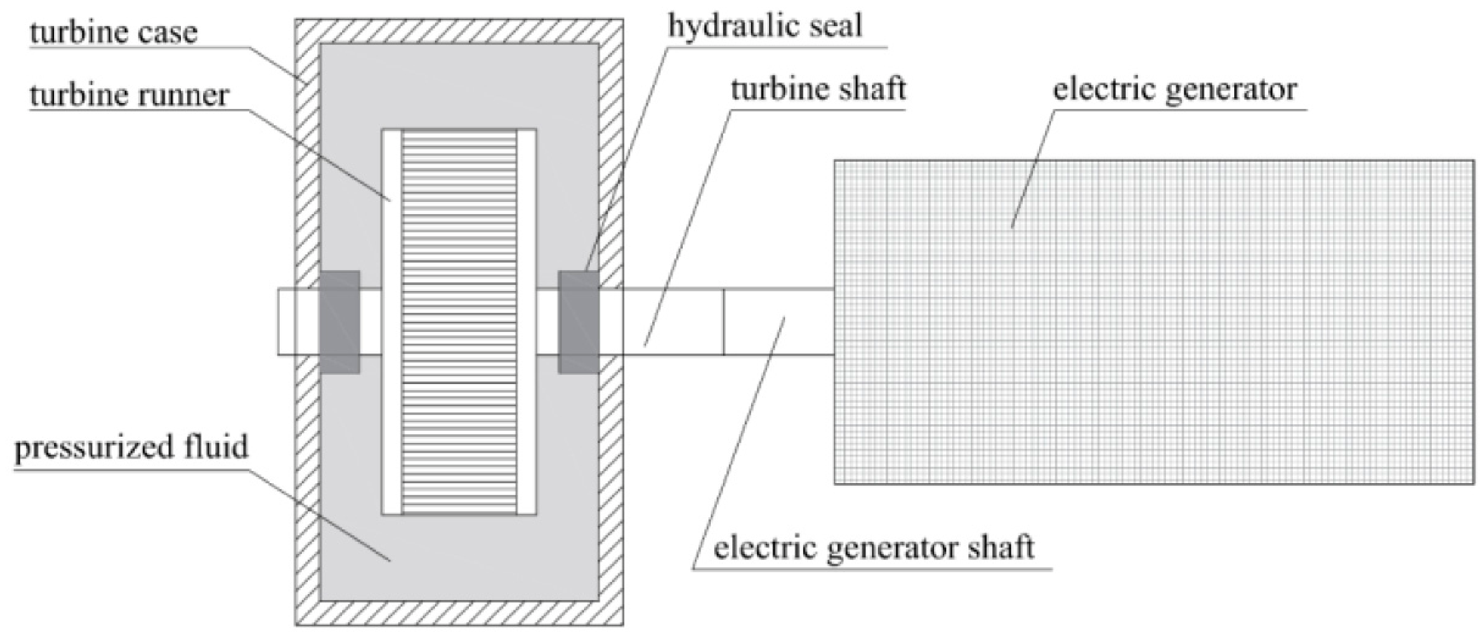
The electric power of the new device is generated by means of a PRS turbine. This turbine, like all traditional hydraulic turbines, follows a typical scheme in which two machines—the hydraulic turbine and the electric generator—are mechanically connected through their respective drive shafts. This arrangement allows the hydraulic runner, which is immersed in the pressurized fluid, to operate while the generator remains in an atmospheric environment. For this purpose, the hydraulic turbine always incorporates a hydraulic seal that enables the transition of the turbine shaft between the two different environments (
Figure 1).
In the case of low-power turbines and the high-pressure hosting pipe, the use of hydraulic seals provides a significant dissipative loss [
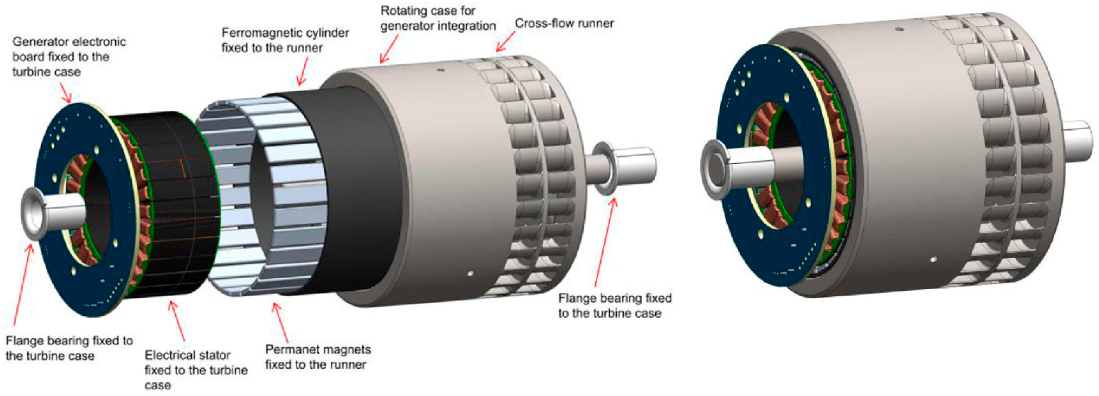
5] due to the sliding between the fixed and the rotating components. To eliminate these losses, the hydroelectric configuration of the new sensor integrates the generator within the hydraulic runner, merging both in the pressurized fluid environment and thereby eliminating the need for hydraulic seals. A rotating cylindrical case, with the same rotor diameter, is added on one side of it (
Figure 2) to provide support for a ferromagnetic cylinder equipped with the generator’s permanent magnets. The central part of the resulting cylinder is occupied by the stator of the electric generator, which consists of a ferromagnetic core wound with copper windings and the associated electronics. The entire electric stator is attached to the turbine case, with the only connection to the unpressurized external environment being made by the electrical cables using a static hydraulic seal. With this configuration, the entire generator is immersed in water and electrically isolated from it by a dedicated layer of epoxy resin.
Figure 2 shows the structure of the hydraulic runner–electric generator assembly.
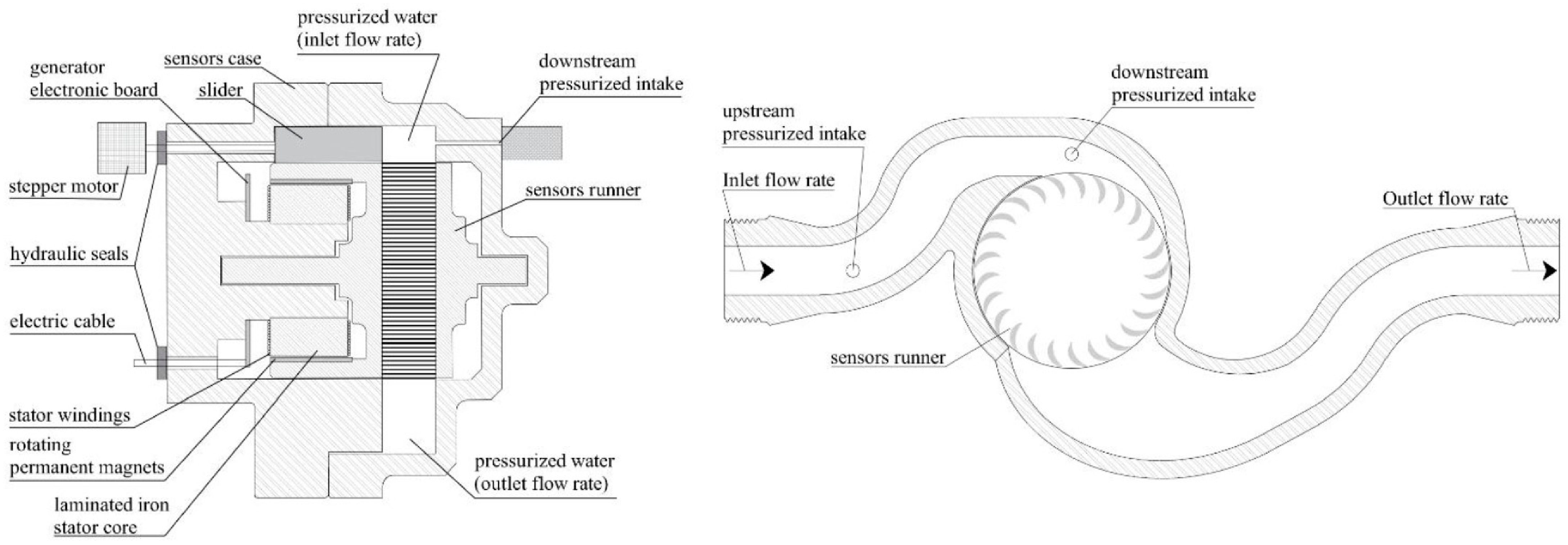
To maximize the electrical power generation efficiency of the turbine and to maintain a constant velocity ratio, the new sensor is also equipped with a slider (
Figure 3), with the aim of controlling the width W of the flow cross-section immediately before the inlet of the hydraulic runner according to the actual value of the flow rate. The device configuration is completed with a differential pressure transducer, which measures the water pressure difference between the sensor’s inlet section and the section corresponding to the variable narrowing defined by the slider. Given the slider position and the differential pressure measurement, the new sensor computes the instantaneous water flow rate using the algorithm based on the Venturi effect in converging pipes.
The power provided by the generator is used for five main functions: (1) battery recharging; (2) regulation of the runner’s rotational speed to the design value; (3) stepper motor powering for slider actuation; (4) supplying internal devices; (5) supplying external devices. Function (1) is achieved through a current-controlled battery charger, with the aim of guaranteeing the availability of electrical energy in the event of low or zero water flow; Function (2) is implemented by dissipating part of the generated power in a ballast electric load using a Pulse Width Modulation (PWM) system controlled by a Proportional–Integral–Derivative (PID) algorithm.
2.2. Test Results
The volume error of the device has been estimated via comparison with certified master meters, i.e., Endress & Hauser DMA50-AAAAA1 in the main line for flow rates greater than 0.4 L/s and Endress & Hauser DMA20-AAAAA1 in a smaller branch line for flow rates below 0.4 L/s.
According to the European Directive 2014/32/UE MID (Measuring Instruments Directive), the volume estimation error must be evaluated at four characteristic flow rates. For our prototype, the four characteristic flow rates and the corresponding errors are reported in
Table 1.
2.3. Electrical Power Production
Under nominal operating conditions, the generated electrical power is approximately 50 W and can exceed 100 W at higher water flow rates. For a constant nominal flow rate of 2 L/s, the corresponding daily energy production is approximately 1.2 kWh. In the case of typical domestic water usage, the estimated average generated power is around 2.5 W, which corresponds to approximately 60 Wh per day.
Author Contributions
Conceptualization, M.S., G.L.C. and T.T.; methodology, M.S., T.T.; software, C.P. and G.L.C.; validation, M.S.; formal analysis, M.S.; investigation, C.P. and G.L.C.; resources, T.T.; data curation, C.P.; writing—original draft preparation, M.S., C.P., G.L.C. and T.T.; writing—review and editing, M.S.; supervision, T.T.; project administration, T.T.; funding acquisition, T.T. All authors have read and agreed to the published version of the manuscript.
Funding
This work was supported by the project “PERIMA2—Azione 1.1.1 POC 2014–2020 Completamento graduatoria Azione 1.1.5 P.O. FESR SICILIA 2014–2020 Cod. Prog 084321030293 CUP G98I18000560007”.
Institutional Review Board Statement
Not applicable.
Informed Consent Statement
Not applicable.
Data Availability Statement
The data supporting the findings of this study are available from the corresponding author upon reasonable request.
Conflicts of Interest
The authors declare no conflicts of interest.
References
- Najarzadegan, M.R.; Moeini, R. Maximizing the coverage of quality sensors in the water distribution network (case studies: Lee and Deininger and the second and the third EPANET networks). Results Eng. 2025, 25, 104334. [Google Scholar] [CrossRef] [Scilit]
- Bezerra, D.; Giudicianni, C.; Creaco, E.; Meirelles, G.; Brentan, B. A novel approach based on graph signal processing and sampling theory to set pressure sensors in water distribution networks. Expert Syst. Appl. 2025, 270, 126306. [Google Scholar] [CrossRef] [Scilit]
- Rao, C.K.; Sahoo, S.K.; Yanine, F.F. An internet of things–based intelligent smart energy monitoring system for solar photovoltaic applications. In Performance Enhancement and Control of Photovoltaic Systems; Elsevier: Amsterdam, The Netherlands, 2024; pp. 375–416. [Google Scholar] [CrossRef] [Scilit]
- Uchiyama, T.; Takamure, K.; Okuno, Y.; Sato, E. Development of a self-powered wireless sensor node to measure the water flowrate by using a turbine flowmeter. Internet Things 2021, 13, 100327. [Google Scholar] [CrossRef] [Scilit]
- Picone, C.; Sinagra, M.; Tucciarelli, T. A new regulation system for Crossflow type turbines for water management industry. Energy 2025, 328, 136695. [Google Scholar] [CrossRef] [Scilit]
| Disclaimer/Publisher’s Note: The statements, opinions and data contained in all publications are solely those of the individual author(s) and contributor(s) and not of MDPI and/or the editor(s). MDPI and/or the editor(s) disclaim responsibility for any injury to people or property resulting from any ideas, methods, instructions or products referred to in the content. |