1. Introduction
Many technical systems, including ones created by small development teams, integrate multiple individual components that are ordered separately from other manufacturers and assembled together to form the complete product. This trend has become the norm to such an extent that manufacturers and suppliers have begun considering automation and artificial intelligence as technologies to assist the component procurement process [
1,
2]. For example, a laser projection system consists of one or more laser diode assemblies, a scanner assembly, electronic boards for the control of these assemblies, heatsinks, fans, optical elements, such as lenses and dichroic mirrors, and possibly other components depending on the specific application. Many of these components are purchased premade and then included as part of the laser projection system without the need to do the respective design and development work for each component.
Nevertheless, some application scenarios may require system functions and capabilities that cannot be implemented easily, reliably or cheaply enough by an existing component on the market. Furthermore, premade components (especially low-priced ones) often come as black boxes without any documentation. In this case, neither the system development team nor the system buyer may be able to perform any adjustments or changes. Any availability guarantee, quality assurance, manufacturing consistency, upgrade path or support related to such components may be non-existent. Due to these reasons, assembly alone may not satisfy the application needs. The design and development of custom easy-to-use, reliable, and, when possible, cheap components may be required for enabling one or more system features depending on the application scenario.
A real-world example of such an application scenario is the construction (or adaptation) of a laser projection system for outdoor projections in unknown environmental conditions, possibly without supervision. One requirement in this scenario is to devise and implement a suitable strategy for measurement and control of the temperature and humidity within the laser system case. The laser diode projection should turn on or off depending on the measured values in order to keep the laser diodes safe. Configuration parameters, such as minimum or maximum operating temperatures, should be adjustable via a suitable communication interface. An extension of this feature is to use the same interface for general remote monitoring and control as well as for firmware updates. Another requirement in some situations may be to change or turn on/off the laser projection at predefined time intervals. This may be needed for advertising purposes or to turn the laser projection off during the day. Again, the provided timekeeping functionality should be configurable by the developer or user. A third requirement may be to turn on/off internal or external devices, such as fans, heating elements, light-emitting diode (LED) projectors, or pan-tilt equipment, depending on the state of the laser projection system.
The paper discusses the design and development of a microcontroller board for environmental control and device management, which was created to answer the scenario requirements outlined above while providing sufficient level of reliability, consistency and upgradability. Existing solutions on the market were not satisfactory, as they were missing features or had issues with the configurability or reliability that would render the whole laser projection system unusable. Despite this specific application scenario giving the impetus for the board design and development, it must be pointed out that the usage of the proposed microcontroller board is not limited to laser projection systems. Any system operating in unknown environmental conditions may find the board useful, especially if remote monitoring and control capabilities are a desired feature or upgrade.
The next paper section discusses some related work. Then, the hardware architecture of the microcontroller board is presented, implementation details are discussed, some experimental results are shown, and directions for future improvement are outlined.
2. Materials and Methods
The next subsection discusses briefly some works on the topics of hardware design and development for temperature and humidity management, timekeeping and device control as well as remote monitoring and control, after which the proposed microcontroller board is presented.
2.1. Related Work
Temperature and humidity management is a popular topic in the field of embedded systems [
3,
4,
5,
6,
7]. The references discuss monitoring, communication and data transmission in the context of outdoor solar panels [
3], control methods for air-conditioning equipment in buildings [
4], control systems for server rooms [
5], greenhouses and agriculture [
6], and innovative power sources and supercapacitors [
7]. It is clear that every application scenario has its own specific requirements and needs for temperature and humidity measurement and control based on the involved technical devices and the environment they work in. The same is true for the target application scenario of this paper regarding laser projection systems.
Time measurement and timekeeping functions are another popular topic in electronics [
8]. They may be implemented via real-time clock (RTC) modules, global positioning system (GPS) modules, or the network time protocol (NTP) in case of Internet connectivity. In [
9], a DS1302 integrated circuit (IC) is used for timekeeping in combination with an Arduino microcontroller in an application for microclimate monitoring of an experimental greenhouse. In close analogy, in [
10], an RTC module is used in conjunction with NTP for the real-time monitoring of climatic variables and photovoltaic generation in a smart grid application. In case of connecting to remote systems, remote time may be used directly instead of adding RTC modules or ICs [
11]. Another temperature measurement application using a 32-bit microcontroller in conjunction with RTC functionality is discussed in [
12]. Internal or external device control may be implemented via relays [
13] or MOSFETs [
14] even for relatively high voltage levels. Microcontroller-based communication and data transmission may also employ a variety of different technologies [
15,
16,
17].
Implementing the aforementioned functions in a single compact microcontroller board for the purposes of integrating it into laser projection systems and using it to monitor and control one or more systems (e.g., LED projectors, fog generators, sound systems, pan-tilt equipment, etc.) that support the laser projection in a way that is flexible and configurable by developers and end users is the purpose of the work described in this paper.
2.2. Hardware Architecture of the Microcontroller Board
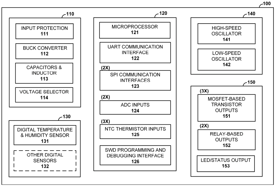
The hardware architecture of the microcontroller board (100) consists of several different component groups (
Figure 1): a power supply group (110), a microprocessor group (120), a digital sensor group (130), an oscillator group (140), and an output group (150).
The power supply group (110) includes a subgroup for input protection (111), a buck converter (112), capacitors and inductor (113), and a voltage selector (114). The input protection (111) includes an SMD fuse, a TVS diode and an electrolytic capacitor of 330 µF or more. The buck converter (112) may supply between 3A and 5A of current from an input supply voltage in the range 9 V to 24 V depending on the exact model of the IC. Its operating frequency is around 600 kHz, permitting the use of a small-sized inductor (113) with an impedance around 10 µH. The relatively high current limit leaves enough room for expansion via additional digital sensors (132) or add-on communication modules attached to the interfaces (122) or (123). As is, the power consumption of the board is generally measured in hundreds of mA at a power efficiency of around 85%, which enables the printed-circuit board (PCB) to function as a heatsink for the buck converter via its ground plane on the reverse side. There are several multilayer ceramic input capacitors (113) with a total value of about 100 µF at the output of the power supply group (110) that serve as intermediary energy storage. The voltage selector (114) sets the output voltage at 3.3 V by means of a resistor divider. This voltage value is determined by the other component groups and may be changed slightly depending on the included sensors (130).
The microprocessor group (120) includes the microprocessor (121), a UART (universal asynchronous receiver/transmitter) communication interface (122), two SPI (serial peripheral interface) communication interfaces (123), two ADC (analog-to-digital converter) inputs (124), three NTC (negative temperature coefficient) thermistor inputs (125), and an SWD (serial wire debug) programming and debugging interface (126). The microprocessor (121) belongs to the STM32F0 product line of STMicroelectronics, Geneva, Switzerland [
18] and may undergo an upgrade to a newer STM32G0 model [
19] in the near future. It is a 32-bit ARM Cortex-M0 microprocessor with hardware support for the communication interfaces (122) and (123) as well as the inputs (124) and (125). It also controls the functions the other component groups (130), (140) and (150). The programming and debugging access is implemented via the SWD interface (126). The communication interfaces (122) and (123) are used for connecting to one or more add-on communication modules that implement a specific communication technology, e.g., WiFi or Bluetooth, used for remote monitoring and control. As the input/output pins of the microprocessor (121) belonging to the interfaces (122) and (123) may also serve as GPIO (general-purpose input/output) pins, various modules may be supported by the microcontroller board (100). The ADC inputs (124) may be used to interface with external sensors that have analog outputs, e.g., PIR sensors for movement detection. The NTC thermistor inputs (125) are intended for low-cost analog temperature measurement at some distance from the microcontroller board (100).
The digital sensor group (130) includes a digital temperature and humidity sensor (131) and may be extended by other digital sensors (132) in the near future that connect to the microprocessor via an I2C (inter-integrated circuit) interface. Several sensor models (131) with similar characteristics have been tested, e.g., the SHTC3 by Sensirion, Stäfa, Switzerland [
20] and the HDC1080 by Texas Instruments, Dallas, TX, USA [
21].
The oscillator group (140) includes a high-speed oscillator (141) and a low-speed oscillator (142). The high-speed oscillator (141) contains a quartz crystal trimmed for a frequency of 8 MHz or 16 MHz. It is used as a frequency reference of high accuracy, which is of special importance for communication purposes. The low-speed oscillator (142) contains a quartz crystal trimmed for lower frequencies between 32 KHz and 40 KHz. The STM32F0 product line integrates RTC functionality and uses the oscillator (142) as an accurate frequency reference to implement the time measurement and timekeeping routines needed by the application.
The output group (150) includes three MOSFET-based transistor outputs (151), two relay-based outputs (152) and an LED/status output (153). All outputs are controlled by the microprocessor (121). The transistor outputs (151) are used mainly to power internal system devices like fans or low-voltage heating elements from the board input supply voltage. Support for pulse-width modulation (PWM) provides some flexibility in setting the average output voltage. The relay-based outputs (152) are galvanically isolated from the input supply voltage and may be used to control both internal and external devices. Each output relay has two channels so up to four devices can be controlled depending on the application needs. The LED/status output (153) is used to indicate the system status to the user, usually by means of an LED mounted on one of the system side panels.
2.3. Implementation Details
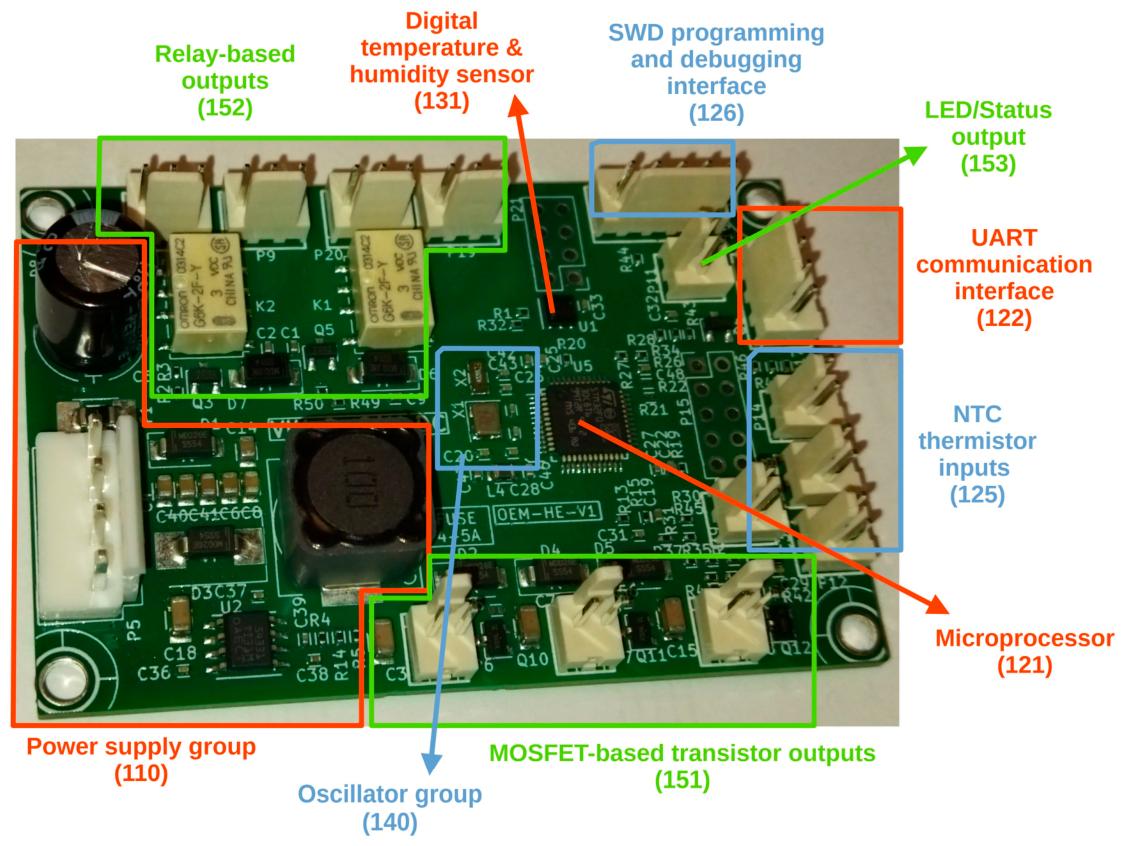
The hardware architecture discussed in the previous section has been implemented in the form of a PCB (
Figure 2). Most of the component groups are referenced in the figure. The SPI communication interfaces (123) and the ADC inputs (124) are accessible via connectors P15 and P21—the two unpopulated connectors on the prototype board illustrated in
Figure 2.
The main components of choice are TPS54531 by Texas Instruments—buck converter U2 (112), STM32F030C8T6 by STMicroelectronics—microprocessor U5 (121), HDC1080 by Texas Instruments—digital temperature and humidity sensor U1 (131), AO3400A by Alpha & Omega semiconductor, Sunnyvale, CA, USA—MOSFET-based transistors Q10, Q11, Q12 (151), and G6K-2F-Y by Omron Corporation, Kyoto, Japan—output relays K1, K2 (152). All of them may be upgraded or downgraded depending on the price-performance ratio required by the specific application scenario. An important point for feature enhancements is that microprocessors from the STM32F0, STM32F1 and STM32F3 product lines are supported without needing modifications of the PCB. Nevertheless, providing support for the newer STM32G0 product line will require some board modifications in the near future.
The microcontroller board has been developed using the open source software KiCad, version 7.0.11 [
22] and programmed using the GNU ARM embedded toolchain, version 10.3 [
23]. Thus, all board development aspects are handled using open source software, toolchains and libraries making the cost and efforts related to future development relatively predictable.
The primary application of the microcontroller board is intended to be inside a laser projection system. The microprocessor (121) monitors the temperatures of two relevant system zones—the laser diode assembly and the main heatsink plate of the system. This is done by using two of the NTC thermistor inputs (125). The general temperature and humidity inside the system case is also tracked via the integrated digital temperature and humidity sensor (131). The MOSFET-based transistor outputs (151) control fans and heating elements mounted inside the laser projection system. In cases of low or high temperatures or high humidity, the relay-based outputs (152) are used to keep the laser projection turned off until the monitored values normalize. In some application scenarios, additional thermoelectric cooling elements may be placed between the laser diode assemblies and the main heatsink plate of the system. This is done to move heat actively from the laser diodes into the heatsink and speed up the cooling of the laser diode assembly at the expense of the total heat generated by the system. Such elements are also supported and may be connected to either a transistor-based output or a relay-based output of the board.
A second role of the board that may be combined with the temperature and humidity monitoring and control is the creation of a flexible daily or weekly schedule for the laser projections. In this case, the timekeeping functions of the microprocessor (121) determine when to activate or deactivate the relay-based outputs (152) depending on a collection of time intervals set by the user. Support for daylight saving time (DST) is also implemented as a custom C-based library.
In many application scenarios, remote monitoring and control functions along with capabilities to make on-site adjustments are requested by the user. For this purpose, the communication interfaces (122) and (123) are used to interface with add-on modules that provide network connectivity. The other side of the connection may be a computer or a mobile phone/tablet if Bluetooth connectivity is provided or, alternatively, a server if TCP/IP connectivity is implemented, e.g., via WiFi. A multiplatform desktop application running under Windows or Linux is developed to give access to the board configuration and provide real-time data visualization. It can be easily customized according to specific user needs and future development plans include porting it to mobile platforms.
3. Results
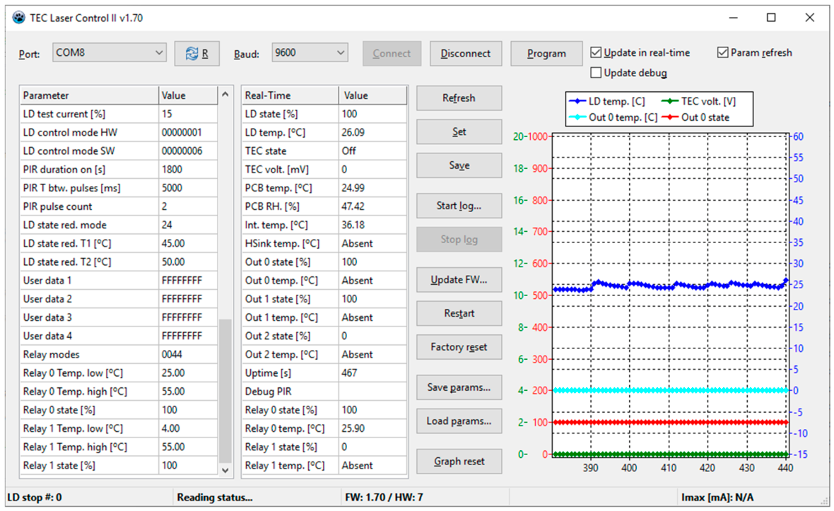
An example of the integration of the microcontroller board in a laser projection system in laboratory conditions is shown in
Figure 3. The multiplatform desktop application is developed in FreePascal, compiler version 3.2.2, using the Lazarus integrated desktop environment, version 4.4 [
24]. It shows the board configuration (left), real-time data (middle), and real-time and historical graphs (right). The right panel shows that the temperature of the laser diode (LD) assembly measured by an NTC thermistor oscillates around 25 °C. The digital temperature and humidity sensor at the board shows a temperature of 24.99 °C and a relative humidity (RH) of 47.42%. Transistor output 0 (Out 0 in the middle panel and the graph) is manually forced to turn on (useful for internal fan testing). Relay output 0 (Relay 0 in the middle panel) turns on between 25 °C and 55 °C, which is a useful working setting for external fans. Relay output 1 is not used at the moment but already set to turn on in the temperature range between 4 °C and 55 °C for future connection to other systems.
This example has the purpose of highlighting the flexibility of the board and the capabilities of the desktop application. Depending on the application scenario, different combinations of settings may be set and, if an add-on communication module is supplied with the board, this can be done at the client’s premises. Remote assistance and remote firmware updates are possible in order to correct functional inaccuracies or extend the feature set if a new client need is identified. Gathering information logs that contain sensor measurements, output states, and time values is another benefit of the board. In case of problems, alarm is raised quickly and the logs facilitate tracing the causes. Last but not least, the desktop application can be customized (usually simplified) to provide access to only certain configuration and real-time parameters that are of interest to a specific user.
4. Discussion and Conclusions
The paper discusses the design and development of a microcontroller board for environmental control and device management. The application scenarios for this board include measuring and controlling the temperature and humidity in laser projection systems, defining a schedule for the laser projection on a daily or weekly basis, turning internal or external devices on and off, and communicating the system state to remote computers and receiving back commands. The development work was initiated with laser projection systems in mind, but the microcontroller board has a broad scope of application and may be used in conjunction with other types of systems.
The contributions of the paper consist in defining an extensible hardware architecture of the microcontroller board, presenting the development work done to build a working prototype, and testing the board in conjunction with the developed desktop application. The extensible architecture may be enhanced with new sensors or communication modules in case of changes in application scenarios. During the development, open source development tools and upgradable components were selected, resulting in a board that is relatively independent from sudden economic events, such as manufacturing shortages or changes in toolchain licensing policies. The experimental tests confirmed the flexibility of the board and its suitability for the application goals. Future work will encompass the provision of additional digital sensors (e.g., SMT172) and connectivity options (e.g., LoRa).