Proceeding Paper

Applications of Twin Counter-Rotating Common-Axis Rotor Systems in Modern Rotorcraft and UAVs †
by
Gabriel Georgiev
* and
Vladimir Serbezov
Department of Aeronautics, Technical University of Sofia, 1000 Sofia, Bulgaria
*
Author to whom correspondence should be addressed.
Presented at the 15th International Scientific Conference TechSys 2026—Engineering, Technologies and Systems, Plovdiv, Bulgaria, 14–16 May 2026.
Eng. Proc. 2026, 150(1), 66; https://doi.org/10.3390/engproc2026150066
Published: 23 July 2026

Abstract

This study represents a comprehensive analysis of the implementation of twin counter-rotating common-axis (coaxial) rotor systems in the design process and technical application of rotorcraft and Unmanned Aerial Vehicles (UAVs). In detail, the conducted literature review clearly illustrates the already usable vehicles and the existing experimental models. The application of a system of two coaxial rotors, one above the other, rotating in opposite directions, eliminates the need for a tail rotor for the provision of directional stability and leads to several additional advantages such as the reduction in the rotorcraft’s weight and enhancement of the directional stability qualities in comparison with the single main rotor configurations. However, the inclusion of two rotors, one above the other, affects lift generation, reducing its magnitude on the lower rotor, while the lift and the thrust of the upper rotor remain relatively unchanged. The implementation of two-rotor systems requires complex algorithms with respect to cyclic and collective pitch control. Ultimately, the analyzed cases indicate the existing gap in the research into coaxial systems concerning the influence of the distance between the two rotors and the collective pitch on the generated thrust and the interferences in cross-flow conditions.

1. Introduction

Coaxial rotor configurations generally consist of two rotors mounted along a common axis, one above the other, rotating in opposite directions. This arrangement provides mutual compensation for the two reaction torques generated by the two rotors and eliminates the need for a tail rotor to ensure directional stability when it is applied to helicopters. However, the generated thrust remains dependent on the axial spacing between the two rotors. A configuration of this kind is well suited for heavy-lift helicopters, despite the increased mechanical complexity associated with the inclusion of two main rotors. In recent years, the widespread adoption of UAVs for a wide range of applications has created new opportunities for the implementation of coaxial configurations owing to the advances in flight control systems and their suitability for specific operating conditions. A brief historical background of the application of coaxial rotor systems in the design of helicopters and UAVs is presented below.

Historical Background

Following Leonardo da Vinci’s introduction of the airscrew in the 1480s, the idea for a coaxial rotor scheme was first proposed by the polymath and scientist Mikhail Vasilyevich Lomonosov in 1754. His design introduced a novel concept consisting of two airscrews rotating in opposite directions, thereby canceling the reaction torques generated by each rotor. The proposed rotor system was intended to lift meteorological instruments.
In 1859, the British Patent Office awarded Henry Bright a patent for the design of a coaxial helicopter developed for attachment to balloons to improve their stability [1]. In addition, several research efforts were undertaken during the second half of the nineteenth century. At the beginning of the twentieth century, the Danish engineer Jacob Christian Hansen-Ellehammer successfully designed, built, and flew a coaxial rotorcraft with rotor blades measuring 5.79 m in diameter [2,3].
Between 1908 and 1910 Igor Sikorsky constructed two experimental coaxial helicopters [1]. Later, in the early 1940s, Nikolai Kamov pioneered the design of coaxial rotorcraft. Helicopters such as the Ka-8, Ka-10, Ka-25 and Ka-27 demonstrated the suitability of the coaxial design configuration for operations from ship decks. Nevertheless, despite these successful applications, the adoption of coaxial rotor systems remained limited throughout the second half of the twentieth century due to their mechanical complexity, the aerodynamic interactions between both rotors, and the increased weight.
The Hiller Aircraft Company developed the first American coaxial helicopter in 1944 [1,2]. The company subsequently produced the XH-44 and the Bendix models K and J [2]. Following the dissolution of Hiller Aircraft, the Bendix model K was transferred to the National Advisory Committee for Aeronautics (NACA) Langley Research Center for research, while the model J was acquired by the Gyrodyne Company of America for further development and testing [2]. During the 1950s, the Bendix model K was extensively used by NACA for research purposes, while the Gyrodyne Company continued to improve the model J over several years. Its development was subsequently continued by the German company Dornier and the Israeli Aircraft Industries [2].
In the twenty-first century, the concept of coaxial rotor systems has regained significant interest with the rapid advancement of the UAVs for a wide range of applications. The relatively small size of UAVs offers several advantages for the implementation of coaxial rotor configurations, primarily due to the reduced mechanical complexity associated with Vertical Takeoff and Landing (VTOL) multirotor vehicles. In 2012, the Jet Propulsion Laboratory at the California Institute of Technology initiated the development of a helicopter capable of operating under Martian atmospheric conditions. The project was subsequently selected for NASA’s Mars 2020 mission. The resulting helicopter, Ingenuity, employs two coaxial rotors rotating in opposite directions, demonstrating one of the principal advantages of the coaxial configuration: the cancelation of the reaction torques generated by the two rotors [4,5]. Furthermore, the coaxial rotor system provides the required lift to sustain flight in Martian atmosphere, where the air density is approximately 1% of that at Earth’s surface. Its compact configuration also enables straightforward integration with and deployment from the Perseverance rover, highlighting its suitability for applications requiring high aerodynamic efficiency and compactness.
From their initial proposal as a design concept to the present day, the coaxial rotor systems have remained a viable configuration for both helicopters and UAVs. However, their suitability depends strongly on the specific operating conditions. The primary objective of this study is to review existing coaxial rotor systems. Furthermore, the study presents the existing research on coaxial rotor systems for helicopters and UAVs, emphasizing the aerodynamic interference between both rotors and its effect on their performance. In addition, the principal advantages and limitations of the coaxial systems are identified. Based on the literature review, the future research directions are proposed.

2. Review of Existing Contemporary Coaxial Helicopters and UAVs

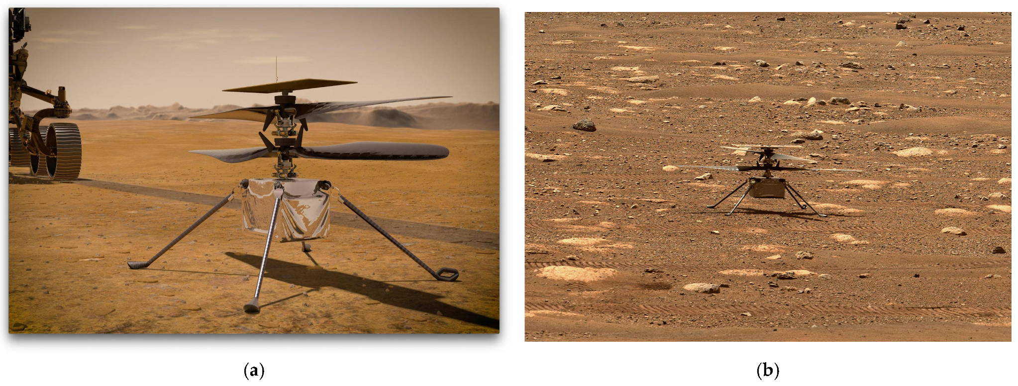
One of the most notable contemporary examples of a coaxial unmanned helicopter is NASA’s Ingenuity. The incorporation of a tail rotor in the extremely thin Martian atmosphere would significantly increase the helicopter’s weight, as its size would need to be comparable to that of the main rotor. Therefore, the coaxial configuration provides maximum thrust, while minimizing the system’s mass. Moreover, this configuration represents an efficient solution for such operating conditions, as it eliminates the need to consume additional energy to generate lateral thrust for compensating the reaction torque. Furthermore, since the lifting area is increased by the two rotors, the total disk area to generate the same thrust is reduced. Figure 1a,b illustrate the concept and show the actual image of Ingenuity captured on the Martian surface.
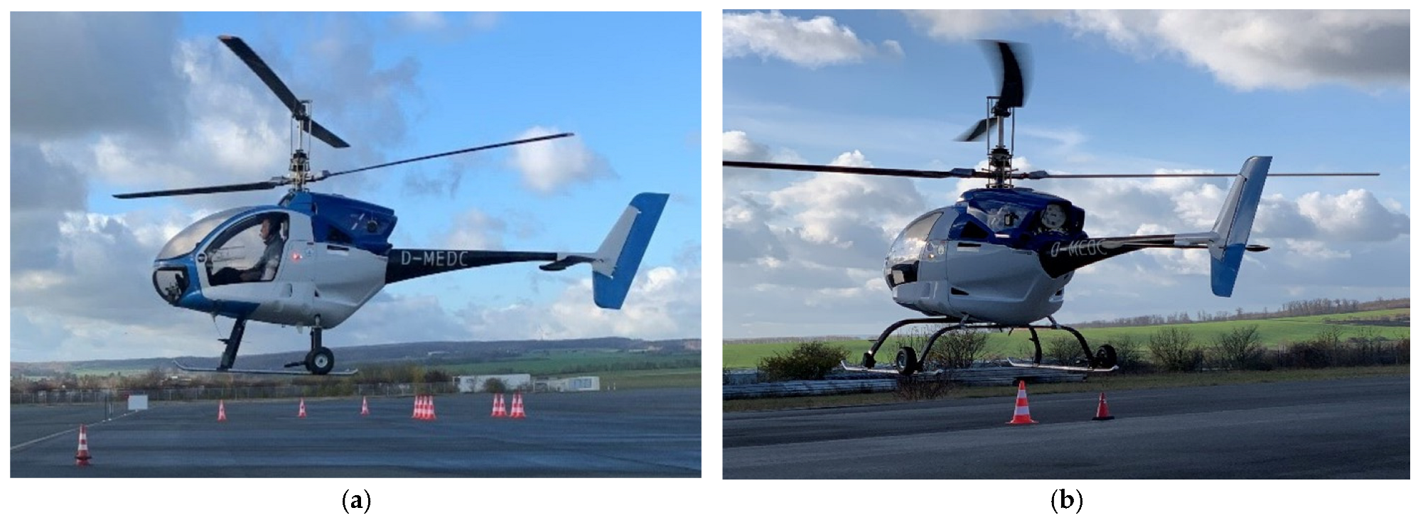
Dreiling Maschinenbau GmbH developed the CoAX ultralight coaxial rotorcraft, with a maximum takeoff weight of 450 kg. Since 2008, several modifications of this rotorcraft have been developed, including the CoAX 2D, which is presented in Figure 2a,b. Furthermore, the company in a collaboration with the Technical University of Munich has been developing an unmanned version of the CoAX 600 with a maximum takeoff weight of 600 kg. The aircraft has successfully completed the flight testing phase.
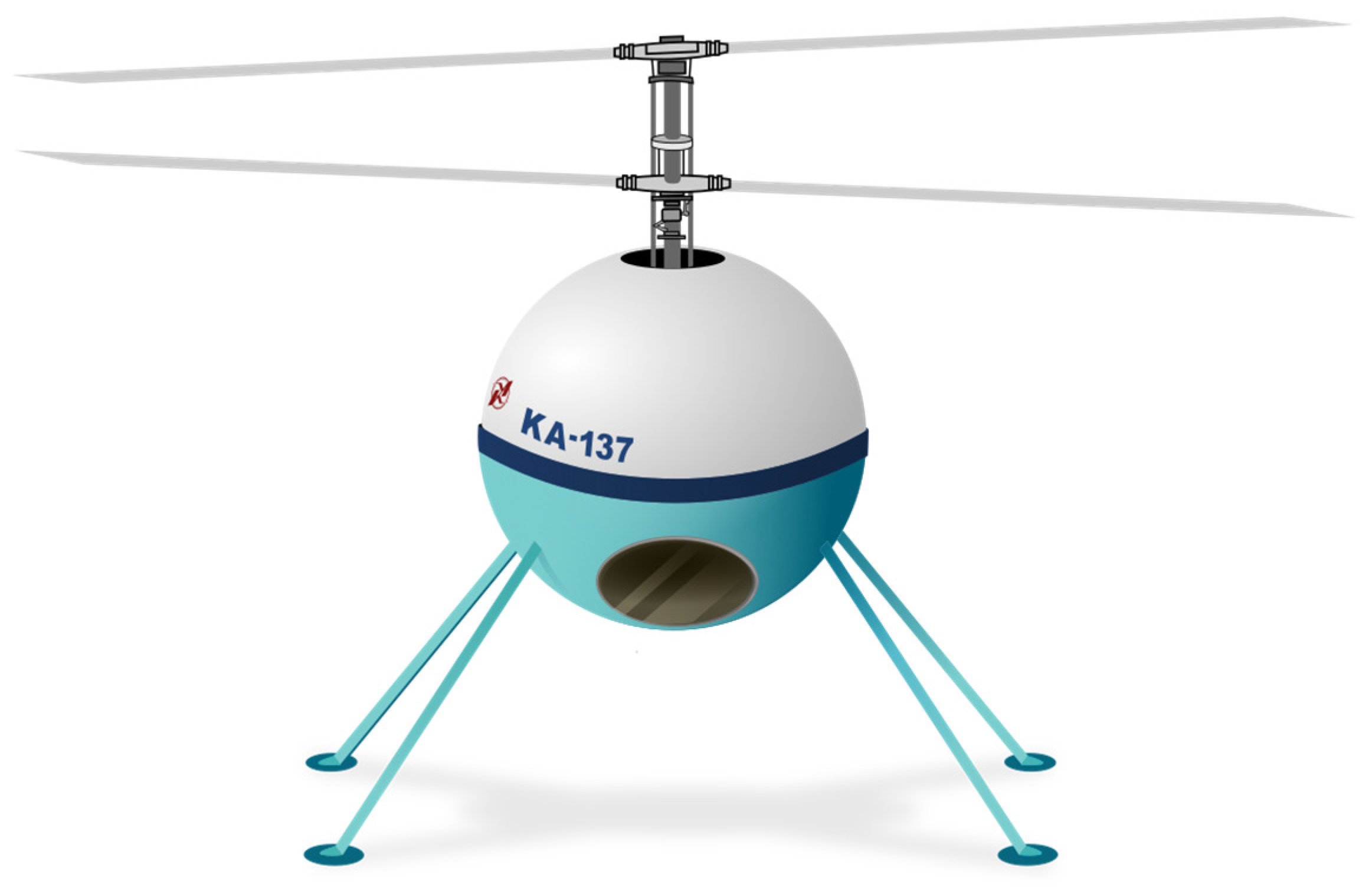
The Kamov design bureau has a long-standing tradition of developing coaxial rotor helicopters. Having designed models such as the Ka-8, Ka-10, Ka-18, Ka-26, Ka-27, Ka-52, and Ka-226 in 1998, the bureau introduced the Ka-137 unmanned multipurpose coaxial helicopter, presented in Figure 3, in three variants: a ship-based version, an automobile-based version and a helicopter-based version.
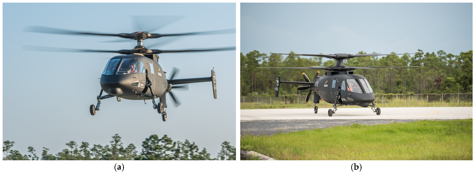
The Sikorsky Aircraft Company has developed several helicopter concepts incorporating coaxial rotor configurations. In 2015, the Sikorsky S-97 Raider, shown in Figure 4a,b, was introduced. The S-97 Raider is a high-speed attack helicopter, equipped with a coaxial main rotor system and a rear-mounted pusher propeller.
The Sikorsky S-97 Raider served as a basis for the development of Sikorsky Raider X, an attack reconnaissance aircraft concept announced in 2019. In addition, Sikorsky in cooperation with Boeing, developed the larger Sikorsky-Boeing SB-1 Defiant helicopter as a candidate for the Future Long-Range Assault Aircraft (FLRAA) program. Since 2022, Sikorsky has participated in the Next-Generation Rotorcraft Capability (NGRC) program, an initiative focused on the development of future medium-class multirole rotorcraft, together with Leonardo and Airbus [13]. Within the program, the company is initially involved in the conceptual design and analysis of two helicopter configurations: the extended version of the conventional Black Hawk and the compound rotorcraft based on a modified version of the coaxial X2 rotorcraft technology, which also incorporates experience gained from the Sikorsky S-97. The NGRC program aims to achieve an initial operational capability for the newly developed rotorcraft after 2035.
In addition, Table 1 compares the hover performance parameters of the selected rotorcraft presented above, highlighting the variations among their hover characteristics.

3. Aerodynamic Research on Coaxial Helicopter and UAV Systems

The coaxial rotors of helicopters and UAVs operate in close proximity, resulting in significant aerodynamic interference between the upper and lower rotors. This interaction modifies the inflow distribution at the lower rotor disk, thereby affecting its aerodynamic loading and the thrust generated by the rotor system. Consequently, several design parameters must be carefully optimized, including the spacing between the rotors, the cyclic and the collective pitch settings, and the associated flight control algorithms. Numerous studies have investigated the influence of these parameters on the thrust generated by each rotor. The scientific studies reviewed in this article are summarized in Table 2.
Russo et al. designed and tested a scaled experimental model to evaluate the performance of a system consisting of two coaxial counter-rotating propellers with different axial spacings between the rotors [21]. The study investigated the thrust and the noise generated by the individual propellers as well as by the coaxial propeller system. The aerodynamic analysis examined the relationship between the generated thrust (T) and the rotational frequency (n) for three axial spacings: h = 1.5 D, h = 1 D and h = 0.65 D, where D denotes the propeller diameter. The results showed that the thrust generated by the upper propeller was largely unaffected by the axial spacing, as its inflow was only minimally influenced by the induced velocity field of the lower propeller. In contrast, the thrust produced by the lower propeller decreased because it operated within the wake of the upper propeller. The increased inflow at the lower disk reduced the pressure difference across the propeller, resulting in a lower thrust output. Consequently, the study concluded that increasing the axial spacing between the two propellers improves the aerodynamic performance of the coaxial propulsion system [21].
The applicability of a UAV with a coaxial rotor configuration for observations in mountainous terrain was investigated by P.S. and Muruga Lal [22]. The compact frame of the coaxial rotor system constitutes the primary design feature that makes this UAV suitable for operation in such environments. Consequently, rotor blades with a radius exceeding 1 m were considered unsuitable for mountainous terrain applications [22]. The authors examined the relationship between the required pitch angle (θ) and the rotational frequency (n) needed to generate a thrust of 30 kg for two- and three-bladed coaxial rotor configurations. The analysis was conducted over a range of air densities, from the standard atmospheric density at mean sea level to the density corresponding to an altitude of 3500 m, using Blade Element-Momentum Theory (BEMT) [22]. The results demonstrated that, for any given rotational frequency (n), the required pitch angle increases with altitude as air density decreases in order to maintain a constant thrust of 30 kg. Furthermore, for both the two-bladed and three-bladed coaxial rotor configurations, a reduction in the rotational frequency necessitates a corresponding increase in the pitch angle to sustain the same thrust level [22]. The study also showed that increasing the rotor radius reduces the pitch angle required to generate the specified thrust [22]. Moreover, the mean lift coefficient generated by the lower rotor was found to be lower than that of the upper rotor because of aerodynamic interference between the two rotors. Specifically, the lower rotor operates within the wake generated by the upper rotor, resulting in reduced aerodynamic performance at any constant rotational frequency (n).
The hover performance evaluation of a Mach-scale coaxial helicopter rotor in several rotor configurations was investigated by Cameron et al. [23]. Specifically, the experimental study considered three configurations: a two-bladed single rotor, a four-bladed single rotor, and a two-bladed coaxial counter-rotating rotor system [23]. The experimental results were presented in terms of the weighted power coefficient ( C P σ ) as a function of the thrust coefficient ( C T σ ) for rotor tip speeds of 153 m s and 190 m s . These results were subsequently compared with numerical predictions using the free-vortex method [23]. In addition, momentum theory was employed to evaluate the profile and induced power components [23]. The analytical results indicated that, relative to an isolated two-bladed rotor, the upper and lower rotors of the coaxial configuration consumed approximately 18% and 49% more induced power, respectively [23]. Furthermore, the distribution of the inflow ratio ( λ ) as a function of the non-dimensional radial position ( r R ) revealed a significant increase in the inflow ratio above the lower rotor. This increase was attributed to the aerodynamic interference generated by the upper rotor and resulted in a reduction in the thrust produced by the lower rotor. Finally, the distribution of thrust between the upper and lower rotors under the condition of balanced system torque remained nearly constant and showed close agreement with the predictions obtained using the free-vortex method [23].
Additionally, Kränzler et al. conducted an experimental investigation of two rotors operating at identical rotational speeds under both hovering and axial flight conditions in a wind tunnel, while varying the separation distance between the rotors [24]. The study demonstrated that the rotor separation distance has a significant influence on the aerodynamic performance of each rotor individually [24]. The measured thrust and the mechanical power required to drive the isolated rotors remained essentially unchanged for rotational frequencies up to 6500 rpm. At higher rotational speeds, deviations from this trend were observed, which were attributed to possible aerodynamic interactions with the experimental support structure [24]. The rotor efficiency was evaluated using the figure of merit as a function of the separation distance between the two rotors. The upper rotor consistently exhibited a considerably higher figure of merit than the lower rotor for all investigated separation distances. In contrast, the overall figure of merit of the coaxial rotor system decreased slightly as the separation distance increased [24]. In addition to the static hover measurements, wind tunnel experiments were performed under axial flight conditions at an angle of attack α = 0 ° for freestream velocities extending to the windmill state. Dynamic measurements were performed for separation distances of 0.08 and 0.5 in order to evaluate the efficiency of the coaxial system as a function of the advance ratio [24]. The experimental results indicated that the axial flight efficiency of the upper rotor was largely unaffected by the rotor separation distance. Conversely, the efficiency of the lower rotor increased as the separation distance decreased, which is opposite to the trend observed under hovering conditions [24]. Furthermore, flow visualization was employed to examine the distributions of vorticity and vertical velocity in the radial direction at a rotational speed of 5000 rpm and a rotor separation distance of 0.2. The velocity measurements reviewed that the vertical velocity between the two rotors ranged from 10 m/s to 12 m/s, increased to 14 m/s at the plane of the lower rotor, and subsequently contributed to the reduction in its figure of merit [24].
Barbely and Komerath simulated the Harrington/Dingeldein forward-flight test case from 1950s using the Rotor Unstructured Navier-Stokes (RotUNS) CFD solver (Sukra Helitek, Ames, IA, USA) with the momentum disk model (DSM) and the discrete blade model (DBS) to evaluate their performance and the corresponding flow-field characteristics [25]. The results for the Harrington single-rotor and Harrington coaxial rotor configurations were analyzed under forward-flight conditions and presented in the terms of mechanical power as a function of the advance ratio. These results were compared with the experimental data and the numerical predictions obtained using CAMRAD II [25]. Additionally, the pressure distributions below and above the two rotor disks in the coaxial configuration were evaluated using a supplementary two-dimensional OVERFLOW simulation of two airfoils separated vertically and rotating in opposite directions [25]. The results showed changes in the lift and drag forces acting on the two airfoils as they moved closer to each other [25]. These changes became more pronounced as the separation distance decreased and the Mach number increased [25]. Furthermore, the authors identified the blade-overlap locations and the blade-vortex interaction regions using a MATLAB code (Version 26.1) [25].
Additionally, Cornelius et al. presented a hybrid Blade Element-Momentum Theory Unsteady Reynolds Averaged Navier-Stoke (BEMT-URANS) model for predicting the performance of single and coaxial rotor configurations, significantly reducing the computational time required by conventional CFD methods [26]. Rotor performance was evaluated in terms of thrust and torque predictions for both the single and coaxial rotor configurations and compared with the available experimental data obtained at the NASA Langley 4 by 22 ft. Subsonic Tunnel [26]. The thrust and torque of the single rotor were predicted with an average error of 4%, whereas the corresponding predictions for the coaxial rotor exhibited an average error of 5% [26].
Berra et al. investigated the aerodynamic interactions between the rotors of a coaxial multirotor system [27]. The authors introduced two rotor models to account for the aerodynamic interactions between the upper and lower rotors of the coaxial configuration [27]. The implementation of the mixer on the lower rotor resulted in reductions in the thrust and power errors of approximately 12 N and 0.043 Nm, respectively [27]. Specifically, the authors proposed two mixer strategies: the coaxial mixer and the reduced-coaxial mixer. The coaxial mixer applies the pseudoinverse of the static control allocation matrix, thereby minimizing the thrust and position errors; however, it increases the attitude error compared with the reduced-coaxial mixer [27]. In contrast, the reduced-coaxial mixer employs second-order equations to determine the rotor velocities and achieves lower attitude and torque tracking errors, although at the expense of higher thrust and position errors compared with the coaxial mixer [27].
Garofano-Soldado et al. investigated the performance of counter-rotating rotors operating in proximity to obstacles [28]. The study was conducted for different spacing distances between the two rotors and for various rotor-to-ground clearance heights, while the rotational frequency was varied. Furthermore, particle image velocimetry (PIV) measurements were performed to evaluate the velocity field within the rotor slipstreams [28]. In particular, the PIV measurements demonstrated the acceleration of the flow velocity in the rotational plane of the lower rotor, followed by a subsequent decrease in velocity as the flow approached the ground surface [28]. Additionally, the authors proposed a semi-empirical model that incorporates existing ground-effect theories while accounting for the rotor-to-ground clearance, the spacing distance between the rotors, and the aerodynamic interactions between them [28]. The proposed model was developed based on the experimental results, the Cheeseman and Bennett theory, correction factors derived from the thrust measurements, and the PIV data. The results indicated that increasing the spacing distance between the two rotors reduced the intensity of the aerodynamic interactions, while the aerodynamic loading evaluated at 90% of the rotor radius became approximately equal to that of a single rotor. Consequently, the ground effect experienced by the coaxial configuration approached that of a single-rotor configuration [28]. Moreover, the ground-effect phenomenon was found to be more pronounced for the coaxial configuration than for the single-rotor configuration [28]. Overall, the results demonstrated that the intensity of the ground effect decreased as the spacing distance between the two rotors increased, owing to the reduction in the aerodynamic interference between the two rotor wakes [28].
A conceptual design study aimed at developing a coaxial quadrotor based on the NASA RVLT vehicle was conducted by Cornelius [29]. The research was performed using the NASA Design and Analysis of Rotorcraft tool and considered the vehicle size, gross weight, and performance for four different design variants [29]. All four variants employed a coaxial rotor configuration but incorporated different design strategies, including control through variable blade pitch versus variable rotational speed, and a motor-rotor transmission using either a gearbox or a direct-drive system [29]. Many existing UAV design concepts adopt the variable rotational speed control approach, whereas conventional rotorcraft designs typically employ variable pitch control combined with a high-speed motor and a gearbox [29]. The former control strategy significantly reduces the overall complexity of the vehicle design [29]. In general, the design process considered three primary objectives: minimizing the gross weight, reducing the rotor size, and minimizing the overall vehicle footprint [29]. The proposed configuration consisted of four coaxial rotors positioned at the four corners of the vehicle and offered several advantages, including lower induced power requirements and smaller blade dimensions compared with an equivalent single-rotor configuration [29]. For the minimum gross weight design, the most suitable control strategy was variable rotational speed control combined with a blade radius of 10 ft [29]. Furthermore, the design targeting the smallest rotor radius was achieved using variable speed control with a gearbox, resulting in the lowest gross weight for the selected rotor radius, namely 5100 lbs for a rotor of 8.5 ft [29].
Holzsager experimentally investigated coaxial propellers for multirotor systems [30]. The study examined the rotational direction of each propeller, the separation distance between them, the rotational frequency, and the blade pitch by measuring the generated thrust, current magnitude, and rotational frequency, with the objective of identifying methods for recovering thrust losses [30]. According to the experimental results obtained for the 13-inch propellers, reducing the spacing between the two propellers from 8 to 2 inches resulted in a 4.5% improvement in performance [30]. Furthermore, the results indicated that the coaxial pair could generate greater thrust when the lower propeller operated at a higher rotational frequency, while the overall efficiency improved when the lower propeller had a larger pitch angle [30]. In particular, varying the propeller pitch for six different four-propeller arrangements produced a maximum thrust ranging from 2960 to 4010 g, with one configuration generating a total thrust equivalent to 401% of the thrust produced by the front propeller [30]. Moreover, Pastor et al. represented an analytical approach for modeling coaxial propellers during the preliminary design phase [31]. The authors developed a vorticity-based computational solver that provides sufficiently low computational times for multidisciplinary analysis and optimization and validated the proposed methodology for coaxial propellers operating at different rotational frequencies [31]. The numerical predictions were compared with wind tunnel measurements obtained for different rotational speeds and rotor spacing distances [31]. Furthermore, Gasior et al. presented a modeling approach for the coaxial propulsion unit of multirotor UAVs [32]. The experimental investigation provided measurements of the generated thrust as a function of the rotational frequency and the applied voltage, and the authors proposed a modeling methodology based on the Takagi-Sugeno fuzzy interface and surface fitting [32]. A first-order inertial element with a variable time constant was incorporated to account for the dynamic response of the propulsion unit [32]. Four independent models were employed to estimate the total generated thrust, and the obtained results demonstrated the potential applicability of the proposed modeling approach to multirotor UAV propulsion systems [32].
Yana and Rand presented an analytical and computational aerodynamic analysis of a coaxial helicopter rotor operating in hover using both a rigid wake model and a free wake model [33]. An optimization procedure was also performed using the analytical model. For an aerodynamically optimal rotor, two conditions had to be satisfied: the induced velocity distribution had to minimize the induced power, and each blade section had to operate at its optimum angle of attack [33]. As a result of the optimization, an optimal helicopter rotor design was proposed in terms of the chord and twist angle distributions [33]. The rigid wake model was found to be sensitive to the selected modeling parameters while capturing several wake effects [33]. In contrast, the free wake model demonstrated good prediction capability and modeling accuracy; however, its computational cost was considerably higher, limiting its suitability for optimization applications [33]. Furthermore, Fernandes employed a free wake model to investigate the aerodynamic wake interactions of a coaxial helicopter rotor [34]. In particular, different inner-rotor spacing distances were considered to quantify their influence on the aerodynamic performance of the rotor system, with lower spacing distances resulting in higher power requirements [34]. Based on the obtained results, the author concluded that the coaxial configuration exhibited superior performance in hover, whereas the single-rotor configuration performed better at high advance ratios [34]. Moreover, the upper rotor of the investigated coaxial system was found to be affected by aerodynamic interference both in hover and at higher advance ratios [34]. Kang et al. investigated the effect of inner-rotor spacing on both an isolated coaxial helicopter rotor and a complete helicopter configuration by means of high-fidelity numerical simulations incorporating the improved Spalart-Allmaras turbulence model coupled with advanced mesh techniques [35]. The results demonstrated that the inner-rotor spacing is a critical parameter influencing blade-vortex interactions, particularly during forward flight [35]. For the complete helicopter configuration, an increase in the thrust fluctuations in the lower rotor was observed owing to the aerodynamic interaction between the lower rotor and the fuselage [35]. Under low-speed forward-flight conditions, increasing the inner-rotor spacing reduced the aerodynamic interactions between the two rotors compared with high-speed forward flight, resulting in an approximately 3% increase in the mean thrust [35]. However, larger inner-rotor spacing requires a more substantial hub system, thereby increasing both the weight and drag [35]. The authors concluded that the hub system generated a drag force corresponding to approximately one-half of the total drag produced by the coaxial rotor configuration [35].

4. Advantages and Disadvantages of Coaxial Rotor Systems

As previously noted, the applicability of the coaxial rotor configuration depends primarily on the operating conditions of the designed rotorcraft. The coaxial configuration can be selected for small vertical take-off and landing UAVs employed in the search-and-rescue and cargo transport operations. Moreover, this configuration is also widely used for military applications, particularly in helicopters with demanding heavy-lift requirements. In this regard, Table 3 presents a summary of the main advantages and disadvantages of coaxial rotor systems for both helicopters and UAVs.

5. Conclusions

In conclusion, this article presents a comprehensive review of the application of coaxial rotor systems in the design and practical implementation of helicopters and UAVs. The increasing use of UAVs in numerous fields of human activity has further promoted the adoption of this configuration because of the operational advantages it offers.
In general, a coaxial rotor configuration consists of two rotors mounted on the same axis and rotating in opposite directions, thereby providing mutual compensation of the reactive torque and eliminating the need for a tail rotor to ensure directional stability. Furthermore, the coaxial configuration can reduce the required power by up to 20% and the overall vehicle weight by approximately 30%, while also decreasing the total disk area required to generate the same level of thrust. The main drawback of coaxial rotor systems is the aerodynamic interference between the two rotors, which reduces the thrust generated by the lower rotor. In addition, the coaxial configuration is characterized by increased mechanical complexity and requires sophisticated control algorithms to coordinate the cyclic and the collective pitch of both rotors.
Numerous researchers have investigated the aerodynamic characteristics of coaxial helicopters and UAVs. Aerodynamic interference reduces the thrust generated by the lower rotor and decreases rotor efficiency in hover, particularly when the spacing between the two rotors is small. However, under axial flight conditions, the efficiency of the lower rotor increases as the distance between the two rotors decreases. Flow visualizations have shown that the velocity in the rotational plane of the lower rotor increases, resulting in a reduction in the generated thrust. Coaxial UAVs exhibit excellent performance characteristics for search-and-rescue operations in the mountainous regions. As the operating altitude increases, greater collective pitch is required to maintain the desired thrust level. Moreover, the propeller radius required to produce the same thrust is smaller than that of an equivalent single-propeller configuration.
Based on the conducted literature review, future research will focus on evaluating the performance of a series of coaxial UAV propellers operating at different rotor spacings and collective pitch angles. The optimal spacing between the two propellers should be determined by evaluating the figure of merit of the individual propellers as well as their combined performance. Furthermore, the influence of collective pitch angles on propeller performance should be quantified. Variations in the induced velocity may first be predicted numerically using established aerodynamic models and subsequently validated through detailed experimental measurements of the velocity profiles between the two propellers. This approach will enable the quantification of the effects of induced velocity, rotor spacing, and collective pitch on the aerodynamic performance of coaxial propellers.

Author Contributions

Conceptualization, V.S.; methodology, V.S. and G.G.; formal analysis, V.S.; investigation, G.G.; resources, V.S.; writing—original draft preparation, G. G.; writing—review and editing, G.G. and V.S.; visualization, G.G.; supervision, V.S. and G.G. All authors have read and agreed to the published version of the manuscript.

Funding

This research was supported by the scientific-research project № 253CH0001-04 “Development of infrastructure and environment for aerospace education and research at TU-Sofia /INSATUS/” by the contract with “Research and development sector at TU-Sofia”.

Institutional Review Board Statement

Not applicable.

Informed Consent Statement

Not applicable.

Data Availability Statement

The data included in this literature review are from previously published sources cited in the article. Correspondence regarding this article should be addressed to the corresponding author.

Conflicts of Interest

The authors declare no conflicts of interest.

References

  1. Coleman, C. A Survey of Theoretical and Experimental Coaxial Rotor Aerodynamic Research; NASA Technical Paper 3675; National Aeronautics and Space Administration, Ames Research Center: Moffett Field, CA, USA, 1997.
  2. Lambermont, P.; Pirie, A. Helicopters and Autogyros of the World; Cassel: London, UK, 1958. [Google Scholar]
  3. Feil, R. Aeromechanics Analysis of Counter-Rotating Coaxial Rotor Systems. Ph.D. Thesis, Technical University of Munich, Munich, Germany, 2019. [Google Scholar]
  4. Johnson, W.; Withrow-Maser, S.; Young, L.; Malpica, C.; Koning, W.J.; Kuang, W.; Fehler, M.; Tuano, A.; Chan, A.; Datta, A.; et al. Mars Science Helicopter Conceptual Design; NASA/TM—2020–220485; National Aeronautics and Space Administration, Ames Research Center: Moffett Field, CA, USA, 2020.
  5. Koning, W.J.F.; Dominguez, M.; Johnson, W. Mars Science Helicopter Rotor Geometry; NASA/TM-20240013701; National Aeronautics and Space Administration, Ames Research Center: Moffett Field, CA, USA, 2024.
  6. NASA/JPL-Caltech. Ingenuity Mars Helicopter on the Martian Surface (Artist’s Concept); NASA Jet Propulsion Laboratory: Pasadena, CA, USA, 2020. Available online: https://photojournal.jpl.nasa.gov/catalog/PIA23720 (accessed on 2 January 2026).
  7. NASA/JPL-Caltech. Ingenuity’s Blades Are Released (PIA24581), NASA Science Photojournal, 9 April 2021. Public Domain. Available online: https://science.nasa.gov/photojournal/ingenuitys-blades-are-released/ (accessed on 2 January 2026).
  8. German Aerospace Center (DLR). DLR’s CoAX 2D Coaxial Helicopter During the Handling Qualities Evaluation Test Flight, Institute of Flight Systems, CC BY-NC-ND 3.0. Available online: https://www.dlr.de/en/ft/research-transfer/research-topics/flight-mechanics-and-handling-qualities/flight-characteristics-handling-qualities-and-flight-mechanics/dlrs-coax-2d-coaxial-helicopter-during-the-handling-qualities-evaluation-test-flight (accessed on 18 February 2026).
  9. German Aerospace Center (DLR). Test Flight of the Coax 2D Helicopter, Institute of Flight Systems, CC BY-NC-ND 3.0. Available online: https://www.dlr.de/en/ft/images/test-flight-of-the-coax-2d-helicopter (accessed on 18 February 2026).
  10. Kamov Ka-137 Illustration; Licensed under CC BY-SA 4.0; Wikimedia Commons: San Francisco, CA, USA, 2023; Available online: https://commons.wikimedia.org/wiki/File:Kamov_Ka-137_illustration.svg (accessed on 18 February 2026).
  11. Sullivan, R. Lockheed Martin/Sikorsky S-97 “RAIDER”, Developed from Sikorsky X2. Flickr, 2018. Public Domain. Available online: https://www.flickr.com/photos/my_public_domain_photos/43005955104 (accessed on 18 February 2026).
  12. Sullivan, R. Lockheed Martin/Sikorsky S-97 RAIDER, Developed from Sikorsky X2. Flickr, 2018. Public Domain. Available online: https://www.flickr.com/photos/my_public_domain_photos/29851948098/ (accessed on 18 February 2026).
  13. Lockheed Martin. Lockheed Martin Sikorsky Advances to Next Phase of Next Generation Rotorcraft Capability Program. Available online: https://news.lockheedmartin.com/Lockheed-Martin-Sikorsky-Advances-to-Next-Phase-of-Next-Generation-Rotorcraft-Capability-Program (accessed on 18 February 2026).
  14. Johnson, W. Rotorcraft Aeromechanics; Cambridge University Press: New York, NY, USA, 2013. [Google Scholar] [CrossRef] [Scilit]
  15. Leishman, G. Principles of Helicopter Aerodynamic, 2nd ed.; Cambridge University Press: Cambridge, UK, 2006. [Google Scholar] [CrossRef] [Scilit]
  16. NASA JPL. Mars Helicopter Ingenuity–Mission Overview and Technical Facts. Available online: https://www.jpl.nasa.gov (accessed on 15 July 2026).
  17. Sikorsky Aircraft/Lockheed Martin. S-97 Raider and SB-1 Defiant Technical Data. Available online: https://www.lockheedmartin.com (accessed on 15 July 2026).
  18. edm aerotec GmbH. CoAX 2D Ultralight Helicopter Specifications. Available online: https://www.edm-aerotec.de (accessed on 17 April 2026).
  19. Institut für Flugregelung (IFR), University of Stuttgart. CoAX 2D Helicopter—Research Platform. Available online: https://www.ifr.uni-stuttgart.de/forschung/Forschungsflotte/Helikopter/CoAX-2D/ (accessed on 17 April 2026).
  20. Russian Helicopters. Kamov Helicopter Specifications and Data Sheets. Available online: https://rhc.ru (accessed on 15 July 2026).
  21. Russo, N.; Marano, A.D.; Gagliardi, G.M.; Guida, M.; Polito, T.; Marulo, F. Thrust and Noise Experimental Assessment on Counter-Rotating Coaxial Rotors. Aerospace 2023, 10, 535. [Google Scholar] [CrossRef] [Scilit]
  22. Ramesh, P.S.; Lal, J.J.M. Hover Performance Analysis of Coaxial Mini Unmanned Aerial Vehicle for Applications in Mountain Terrain. Aviation 2022, 26, 112–123. [Google Scholar] [CrossRef] [Scilit]
  23. Cameron, C.; Karpatne, A.; Sirohi, J. Performance of a Mach-Scale Coaxial Counter-Rotating Rotor in Hover. J. Aircr. 2016, 53, 746–755. [Google Scholar] [CrossRef] [Scilit]
  24. Kränzler, M.; Dufhaus, S.; Stumpf, E. Studies on the influence of rotor distance on the efficiency of a coaxial rotor system. In Proceedings of the 44th European Rotorcraft Forum, Delft, The Netherlands, 19–20 September 2018. [Google Scholar]
  25. Barbely, N.L.; Komerath, N.M. Coaxial Rotor Flow Phenomena in Forward Flight. In SAE 2016 Aerospace Systems and Technology Conference; SAE Technical Paper; SAE International: Warrendale, PA, USA, 2016. [Google Scholar] [CrossRef] [Scilit]
  26. Cornelius, J.; Schmitz, S.; Palacios, J.; Juliano, B.; Heisler, R. Rotor Performance Predictions for Urban Air Mobility: Single vs. Coaxial Rigid Rotors. Aerospace 2024, 11, 244. [Google Scholar] [CrossRef] [Scilit]
  27. Berra, A.; Trujillo Soto, M.Á.; Heredia, G. Aerodynamic Interaction Minimization in Coaxial Multirotors via Optimized Control Allocation. Drones 2024, 8, 446. [Google Scholar] [CrossRef] [Scilit]
  28. Garofano-Soldado, A.; Ragni, D.; Pereira, L.T.L.; Zamponi, R.; Ollero, A.; Heredia, G. Aerodynamic Model of Counter-Rotating Coaxial Rotors Near the Ground. Aerosp. Sci. Technol. 2026, 168, 111112. [Google Scholar] [CrossRef] [Scilit]
  29. Cornelius, J.K. Designing a Coaxial Quadrotor for Urban Air Mobility. In Proceedings of the 10th Biennial Autonomous VTOL Technical Meeting & 10th Annual Electric VTOL Symposium, Mesa, AZ, USA, 24–26 January 2023. [Google Scholar]
  30. Holzsager, J.E. The Effects of Coaxial Propellers for the Propulsion of Multirotor Systems. Master’s Thesis, Graduate Program in Mechanical and Aerospace Engineering, Rutgers, The State University of New Jersey, New Brunswick, NJ, USA, 2017. [Google Scholar]
  31. Pastor, G.; Hartfield, R.; Ahuja, V.; McClearen, J. Numerical and experimental testing of a coaxial propeller for Urban Air Mobility applications. In Proceedings of the AIAA Aviation 2022 Forum, Chicago, IL, USA, 27 June–1 July 2022. [Google Scholar]
  32. Gasior, P.; Bondyra, A.; Gardecki, S.; Giernacki, W.; Kasiński, A. Thrust estimation by fuzzy modeling of coaxial propulsion unit for multirotor UAVs. In Proceedings of the 2016 IEEE International Conference on Multisensor Fusion and Integration for Intelligent Systems (MFI), Baden-Baden, Germany, 19–21 September 2016. [Google Scholar]
  33. Yana, J.; Rand, O. Performance Analysis of a Coaxial Rotor System in Hover: Three Points of View. In Proceedings of the 28th Congress of the International Council of the Aeronautical Sciences (ICAS 2012), Brisbane, Australia, 23–28 September 2012. [Google Scholar]
  34. Fernandes, S.D. Performance Analysis of a Coaxial Helicopter in Hover and Forward Flight. Master’s Thesis, Embry-Riddle Aeronautical University, Daytona Beach, FL, USA, 2017. [Google Scholar]
  35. Kang, S.U.; Shin, S.B.; Myong, R.S.; Lee, H. Investigation of inter-rotor spacing effect on aerodynamics and aeroacoustics of a coaxial rigid rotor helicopter in full configuration using high-fidelity numerical simulations. Aerosp. Sci. Technol. 2025, 168, 110959. [Google Scholar] [CrossRef] [Scilit]
Figure 1. NASA’s Mars Helicopter: (a) Ingenuity on the Martian Surface (Artist’s Concept) [6]; (b) Ingenuity helicopter unlocked its rotor blades, on 7 April 2021, the 47th Martian day, or sol, of the mission [7]. Source: NASA/JPL-Caltech. Public domain.
Engproc 150 00066 g001
Figure 2. CoAX 2D coaxial helicopter during handling qualities evaluation (a), [8]; (b), [9]. Reproduced from the German Aerospace Center (DLR), licensed under CC BY-NC-ND 3.0.
Engproc 150 00066 g002
Figure 3. Kamov Ka-137 illustration [10]. Source: Wikimedia Commons (FOX 52, CC BY-SA 4.0).
Engproc 150 00066 g003
Figure 4. Sikorsky S-97 Raider (a), [11]; (b), [12]. Source: Robert Sullivan, Flickr. Public Domain.
Engproc 150 00066 g004
Table 1. Comparison of hover performance parameters for selected rotorcraft [14,15,16,17,18,19,20].
RotorcraftDisk Loading W S Induced Velocity v i Power Coefficient per Solidity C P σ Thrust Coefficient per Solidity C T σ
Ingenuity≈0.7≈2.6–30.08–0.100.05–0.07
CoAX 2D≈50–100≈4–60.09–0.110.06–0.08
Ka-27≈300–450≈10–140.09–0.110.06–0.08
Ka-137≈200–300≈9–110.08–0.100.05–0.07
Sikorsky S-97 R≈450–600≈13–160.10–0.120.07–0.09
SB-1 Defiant≈600–800≈16–200.11–0.130.08–0.10
Table 2. Summary of the aerodynamic studies reviewed in this article.
AuthorsObject of ResearchResearch Scope
Russo et al. [21]Coaxial counter-rotating rotorsPerformance evaluation
P. S. and Muruga Lal [22]Coaxial mini-UAVHover characteristics
Cameron et al. [23]Mach-scale coaxial rotorHover characteristics
Kränzler et al. [24]Coaxial rotor systemFlight performance
Barbely and Komerath [25]Coaxial helicopter rotorForward flight characteristics
Cornelius et al. [26]Single and coaxial rotorAerodynamic characteristics
Berra et al. [27]Coaxial multirotorsAerodynamic interactions
Garofano-Soldado et al. [28]Counter-rotating rotorsAerodynamic characteristics
Cornelius [29]Coaxial quadrotor vehicle Conceptual design
Holzsager [30]Coaxial propellersThrust losses recuperation
Pastor et al. [31]Coaxial propellersPerformance evaluation
Gasior et al. [32]Coaxial propulsion unit Thrust estimation
Yana and Rand [33]Coaxial rotor systemHover performance
Fernandes [34]Coaxial helicopterWake interactions
Kang et al. [35]Coaxial rotor configurationAerodynamic interactions
Table 3. Advantages and disadvantages of coaxial rotor systems.
Coaxial Rotor Systems
AdvantagesDisadvantages
1.1 Improved Power Efficiency
The use of coaxial rotor systems can reduce the required power by up to 20% due to the absence of a tail rotor. The power normally required for anti-torque compensation in a single-rotor system can instead be redirected to lift generation.
2.1 Rotor-Rotor Interference
The inflow generated by the upper rotor affects the inflow of the lower rotor, resulting in a reduction in the thrust produced by the lower rotor.
1.2 Improved Directional Stability
The directional stability of a coaxial rotor configuration is superior to that of a conventional main rotor and tail rotor arrangement. Crosswinds do not produce a destabilizing effect on a tail rotor because the configuration consists only of two counter-rotating rotors. Moreover, retreating-blade stall characteristics are further improved.
2.2 Performance Limitations for Rotorcraft Flying at Extremely High Forward Speeds at High Collective Pitch Angles ( μ > 0.45 )
Although the coaxial rotor configuration improves high-speed performance, stronger aerodynamic interactions between the counter-rotating rotors at high collective pitch angles result in increased unsteady aerodynamic loads and vibration.
1.3 Enhanced Yaw Control
Coaxial rotor systems use the differential torque generated by the two rotors to provide yaw control. This approach improves directional control accuracy compared with a conventional main rotor and tail rotor system.
2.3 Complex Control Algorithms
Flight control algorithms for coaxial rotor configurations are more complex because the collective and cyclic pitch inputs of both rotors must be synchronized.
1.4 Improved Lift Capability
The use of two rotors sharing the same payload results in a smaller required rotor disk area compared with an equivalent single-rotor configuration.
2.4 Design Complexity
The use of concentric shafts, precision gearboxes and complex mechanisms increases both manufacturing and maintenance costs.
1.5 Weight Optimization
The implementation of a coaxial rotor configuration can reduce the overall rotorcraft weight by approximately 30% owing to the elimination of the tail rotor.
2.5 Blade-Vortex Interaction
The interaction between the wake of the upper rotor and the lower rotor generates increased noise and vibration levels.
1.6 Simplified Piloting
Coaxial rotor configurations provide simpler piloting characteristics because of their inherent lift symmetry.
2.6 Complex Assembly
The assembly of the coaxial rotor system is more demanding and requires greater effort as well as highly qualified personnel.
Disclaimer/Publisher’s Note: The statements, opinions and data contained in all publications are solely those of the individual author(s) and contributor(s) and not of MDPI and/or the editor(s). MDPI and/or the editor(s) disclaim responsibility for any injury to people or property resulting from any ideas, methods, instructions or products referred to in the content.