Proceeding Paper

Manufacturing Technologies Comparison for Nozzles †
by
Svetlana Boshnakova
Center of Competence “Smart Mechatronic, Eco- and Energy-Saving Systems and Technologies”, Technical University Sofia, Branch Plovdiv, 4000 Plovdiv, Bulgaria
Presented at the 15th International Scientific Conference TechSys 2026—Engineering, Technologies and Systems, Plovdiv, Bulgaria, 14–16 May 2026.
Eng. Proc. 2026, 150(1), 68; https://doi.org/10.3390/engproc2026150068
Published: 23 July 2026

Abstract

During operation, several parts of the thermal reactor burners sustain heavy damage and need to be replaced. Different solutions for parts manufacturing are investigated: thermal spraying, Selective Laser Melting (SLM), and hardfacing by Directed Energy Deposition plasma arc (DED-arc). Based on the comparison to original material and the duration of usage, application of those three methods for replacement is studied in order to determine the most suitable one, with Additive Manufacturing (AM) being proposed for targeting the problem. Thermal-sprayed items have a zirconium-oxide-based outer layer. SLM produces a monolithic item, while with the help of DED-arc, a composite structure with a sound metallurgical bond between the base and the added material is produced. The microstructures with the interface zones are observed. Samples are machined and ground, and their friction characteristics are taken with the help of acoustic emission (AE) and Electrical Contact Resistances (ECR) sensors during scratching. As a result, overlaying of the base stainless steel by DED-arc is proposed due to the better metallurgical stability of the added mixture in a hot environment above 800 °C and its hardness characteristics.

1. Introduction

Additive Manufacturing is a very promising field for repair tasks. There are several methods that can be applied. According to БДC EN ISO/ASTM 52900:2022 [1], seven categories are given as follows:
  • Vat Photopolymerization,
  • Material Jetting,
  • Binder Jetting,
  • Material Extrusion,
  • Powder Bed Fusion (where we find the SLM),
  • Directed Energy Deposition and
  • Sheet Lamination.
It is under the DED category that the Thermal Spray Additive Manufacturing (TSAM) might be included due to its specific layer-by-layer application of the coating in this field.
Versatile materials can be selected, and with a combination of post-processing, final products can be obtained. One such application is for the replacement of nozzles. During operation, several parts of the thermal reactor burners sustain heavy damage and need to be replaced. Generally, nozzle material has to have high thermal endurance and be applicable for the zone classification of the processed media, as well as be wear-resistant. Additional characteristics can be obtainable and easy to 3D print after that machined [2,3,4].
In repair activities, traditional manufacturing technologies are struggling to substitute parts that are efficient and have high temperature tolerances. That is why 3D printing is a very good alternative and delivers results. For burners’ nozzles, an improved design is needed that aims at reducing operating temperatures, lowering the dynamic load, and extending the lifespan. What is most important is that the new nozzles have to be fit for direct replacement of the originals [5,6,7].

2. Experimental (Materials and Methods)

Based on the comparison to original material and the duration of usage, the application of those three methods for replacement is studied in order to determine the most suitable one, with AM being proposed for targeting the problem. Thermal-sprayed items have a zirconium-oxide-based outer layer; SLM gives a monolithic item, while with the help of DED-arc, a composite structure with sound metallurgical bond is produced. Actual data with the corresponding information is available only for the original part and the thermally sprayed one. Focus is given on the experimental results and possible replacement by the DED-arc process.
A comparison is made to evaluate SLM, TSAM, and DED-arc based on cost, structural characteristics, and industrial application challenges solved [8,9,10]. Table 1 summarizes the results, and it is concluded that if the application demands absolute precision and monolithic complexity, SLM is required despite the cost. If the goal is rapid, low-cost surface buildup, TSAM is the winner. However, for heavy-duty industrial repairs where structural strength must be balanced with budget, DED-arc [11,12] is the most viable solution.
The three corresponding solutions are discussed in detail. Focus is given on the experimental results and possible replacement by the DED-arc process. The process of deposition of a powder mixture of tungsten carbide (WC) and a cobalt-based alloy consisting of complex carbides in a CoCr alloy matrix (Stellite 6) onto austenitic stainless steel substrates for reinforcement is investigated to obtain representative samples with a two-layered structure. БДC EN ISO/ASTM 52900:2022 gives the principles of the process, DED-arc, and by following it, layers of thickness 5 mm formed by Stellite 6 and an added volumetric fraction of WC 20% for structure enhancement are obtained.

2.1. Basic Configuration

The thermal reactor of the Sulfur Recovery Unit needs pilot nozzles’ replacement due to the high temperature of operation in the chamber, around 1630 °C, and sour acid service with high content of H2S. Pressure inside is around 1.62 barG, and the feed natural gas is at a temperature of 34 °C. Initial material specified by the manufacturer is EN-GJSA-XNi35. The duration of service is short as the pilots are completely damaged. Conventional machining techniques are used to produce the first set of nozzles with the available material XH45Ю according to ГOCT 5632-72 [13]. The exploitation period is approximately one year for 10 pieces. Possible alternative materials like J93403, J94003, J94224, J95705, J94605, and NX are evaluated for suitability but not used. Photos of the initial pilot nozzles can be seen in Figure 1.

2.2. Thermal Sprayed Solution

Rakhadilov et al. in [14] demonstrate that increasing the wire feed rate and decreasing the standoff distance during arc spraying results in thicker, denser steel coatings with reduced porosity. That is why the second solution is chosen: by means of thermal spraying, which is not classified as an Additive Manufacturing process as per ISO 17296-2:2014 [7], nozzles were produced with base material stainless steel X15CrNiSi25-21 (W.N. 1.4841, UNS S31400—Type 314) and ceramic coating that is temperature resistant. The chemical composition of the base material is given in Table 2.
As a metal ceramic powder for thermal spraying, the “MetaCeram 28085” product of Castolin is selected, which is very well suited for thermal insulation and thermal conductivity. The flame spray equipment is CasoDyn DS 8000, Impact Innovation GmbH, Haunritzen, Germany. The achieved layer is of thickness 0.3 ÷ 0.5 mm and is a zirconium-oxide-based, oxygen-stabilized complex compound with specific grain size distribution and controlled morphology. First, a bond coat approximately 0.15 mm thick is applied using another Castolin product, 510000 alloy, followed immediately by a coat of MetaCeram 28085. After the nozzles were machined and the final product obtained, they were placed inside the thermal reactor.
The pilots of the burner have been in service for three years since it was finally possible to give them access. It was revealed that they were burned and completely damaged. This suggests that in the harsh conditions it is advisable to substitute the fire-facing metal with a different one of more resistant metallurgy like Inconel, Incoloy or Stellite.
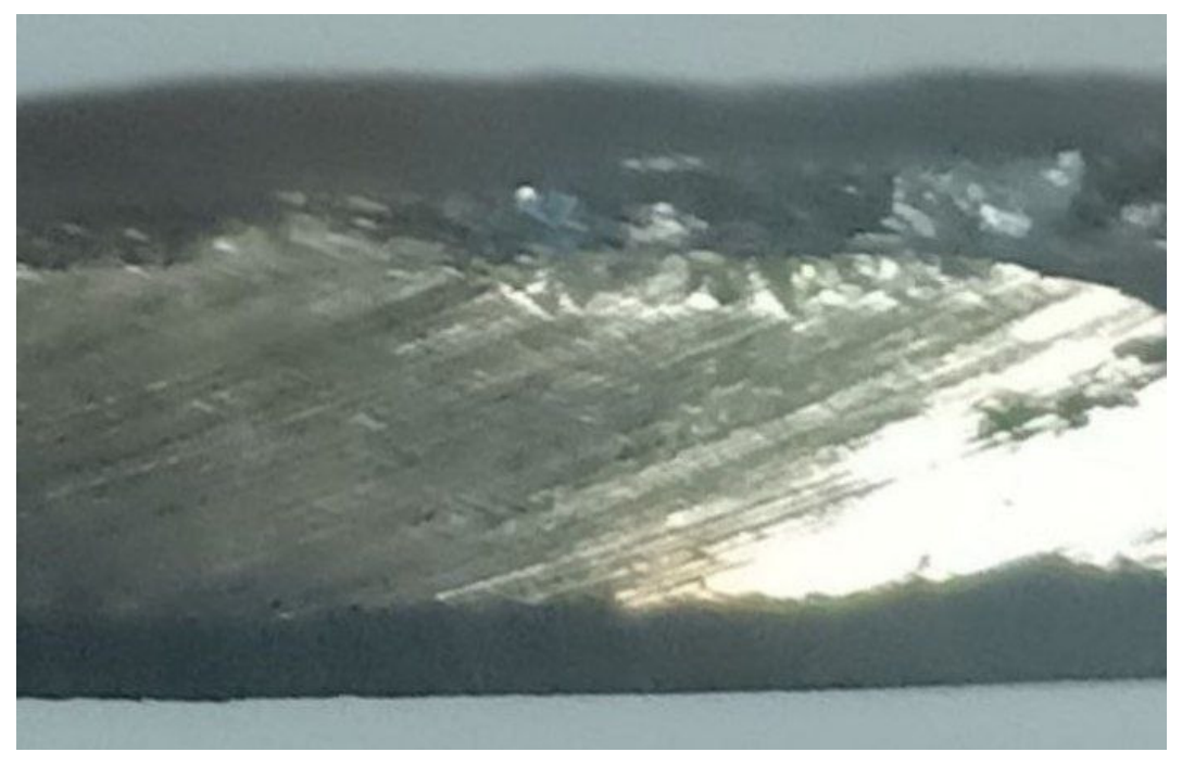
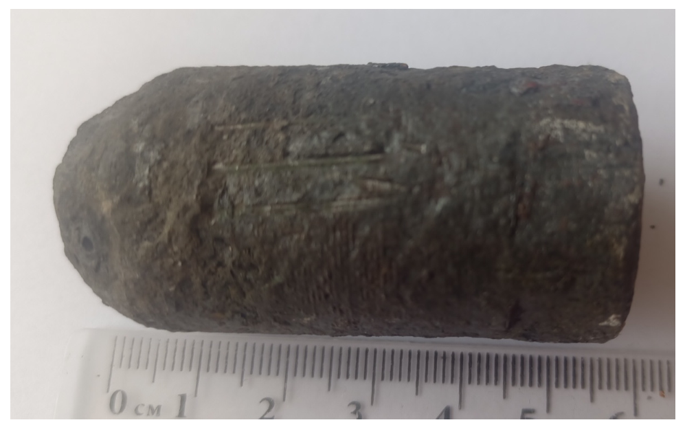
The general view of the TSAM nozzles did not differ much from that shown in Figure 1, except for the white coating. Nevertheless, the retrieved result after the service is shown in Figure 2, as the condition is very bad.

2.3. Selective Laser Melting

Following the experience with the repair activities, some knowledge was gathered and future practices established. Meanwhile, a similar burner to the thermal reactor of the Sulfur Recovery Unit failed in service due to the primary nozzles. The burners’ nozzles in the thermal chamber of the Sulfur Acid Recovery Unit are of a more complicated design, but their purposes are very similar. They were from Hastelloy C22 material and comprised two different pieces that needed to be assembled so that the product could be complete. Also, a special distance washer of different thickness has to be set between to maintain the desired flow. There are differences in the size and orifice of the nozzle, but the failure mechanisms of the part are the same.
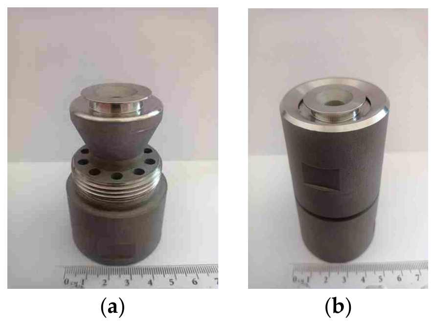
Selective Laser Melting, a Powder Bed Fusion type of Additive Manufacturing process as per ISO 17296-2:2014, was selected for manufacturing. Hastelloy C22 powder with a particle size in the range of 30-40 µm (micrometers) and a 3D printer ProX DMP 200 (3D Systems, Rock Hill, SC, USA) were used. The base plate had dimensions of 140 mm × 140 mm × 90 mm, and the accuracy was +/−0.05 mm, whereas the surface roughness was 5 Ra µm. The produced nozzles are represented in Figure 3.
Those nozzles had advanced metallurgical properties due to the uniform material used and the complete fusion of the layered structure [10].

2.4. Directed Energy Deposition Plasma Arc (DED-Arc)

DED-arc stands out in the industrial sector primarily due to its exceptional ability to deposit material directly onto existing components, making it the premier choice for the repair and restoration of high-value parts like industrial nozzles. Unlike other additive methods, DED-arc offers a superior metallurgical bond that ensures structural integrity comparable to the base metal, providing high resistance to thermal and mechanical fatigue. This technology is characterized by high deposition rates that significantly shorten production and repair cycles, especially for large-scale components that would be impossible to fit into a standard powder bed system. Its flexibility is further enhanced by the capacity for multi-material integration, allowing for the creation of functionally graded layers or the application of specialized hardfacing only on critical zones. Furthermore, DED-arc provides a cost-effective middle ground because it can utilize relatively inexpensive powder feedstock while maintaining a much smaller heat-affected zone than traditional welding, which minimizes part distortion and preserves the original material properties. Ultimately, its compatibility with robotic arms and rotating table systems allows for a large build envelope and near-net-shape production, effectively reducing material waste and the need for extensive post-processing.
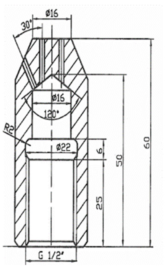
A possible solution for nozzle replacement can be found in the application of the DED-arc process, but it is still under investigation and testing. For elevated temperatures, a cobalt-based superalloy Stellite type with WC particle reinforcement is selected. Figure 4 shows the drawing of the burner’s nozzle, and Figure 5 shows a representative sample of the cut piece with the two bonded materials—the underlying base of common inexpensive stainless steel and fire-facing, hard, and resistant coating.
The choice for base material is stainless steel type X5CrNi18-10. Over it, a mixture of commercially available Stellite 6 (Deloro Stellite® 6, GmbH, Germany) and 20 vol% WC particles, with a grain size of 63–150 µm, is applied. Chemical compositions of the base material and the Stellite 6 are given in Table 3 and Table 4, respectively. The melting point and specific weight of Stellite 6 are 1265–1375 °C and 8.42 gcm−3, whereas those for WC are 3058 °C and 15.77 g cm−3, respectively [15]. This means that the thermal selection of properties is an applicable one [16].
The process of DED-arc deposition consists of the following stages: powder preparation, delivery into the zone of the melt, and deposition inside the pool produced by the plasma arc [7]. A powder mixture of Cr 17.5, Mo 28, Si 3.4, and the rest Co with 20% vol. WC with a mesh size of −100/+325 (particle diameters between 45 and 150 µm) was used in order to produce a hard, composite coating on stainless steel substrates [15]. The powder mixture was introduced into the shielding gas of the plasma equipment, providing a flow of a defined quantity into the melting pool. A total of 18 samples were produced by varying the parameters of the plasma arc. The optimal parameters were identified as: current of 130 A, powder feed rate of 0.25 g/min, and plasma gas flow of 3 L/min. It was observed that reducing the plasma gas flow rate at a constant current leads to a less concentrated arc, resulting in a wider bead and insufficient energy concentration. In contrast, the higher plasma pressure of 3 L/min ensures superior arc stability and a focused energy density. This is critical for achieving a uniform Stellite 6 distribution and maintaining the high hardness while providing the necessary metallurgical bond with the substrate. Samples are produced on the base material with a powder feeder (carrying gas is argon). The large amounts of carbides present in the microstructures can be described as composites with extremely hard carbides in a softer face-centered-cubic (fcc) Cr-Fe alloy matrix of the austenitic steel [17]. Equipment employed was a 6-axis Reis Robot Plasmastar Source 250 (Reis Robotics GmbH & Co. KG, Obernburg, Germany). A Plasmastar 230 MV powder feeder was used for the addition of the particles. The WC particles were injected in an Ar stream into the tail of the melt pool right after the plasma arc to avoid extra heating in the plasma arc [18].
The application was plasma-assisted with a forced powder mixture. Using the 3-D printing technique avoids complex operations when combining the individual components, which is a typical disadvantage in obtaining composite materials; samples are prepared with only one operation from the starting melt, which is chemically defined. Dendrite formation is inhibited by the absence of convection in the crystallizing melt.
Described are characterization methods:
Measurement of structure—micro and macrostructure—the study of microstructure is viewed by microscope Axiovert 200MAT and Axiovision camera for recording. Metallographic samples were etched by a mixture of 10 ml HNO3, 20 ml of HCl, and 30 ml H2O. The samples are held in the solution for 15 min, then polished.
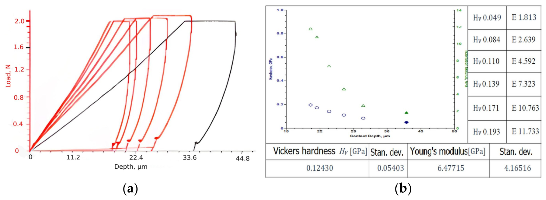
Measurement of hardness/Young’s modulus—the study of the mechanical properties of materials in the range of a few micrometers is performed according to EN ISO 6507-1 [19] with UMT-2M (Bruker-Cetr, USA), working with a load of 2 N and allowing measurement with maximum sensitivity of samples with dimensions in the millimeter range.
Wear and friction characteristics were taken with the help of AE and ECR sensors during scratching.

3. Results and Discussion

Different kinds of tests were used to characterize the obtained samples in order to propose a nozzle fabrication. That is needed to increase the material’s performance and widen its applicability to the specified area.

3.1. Analysis of Structure

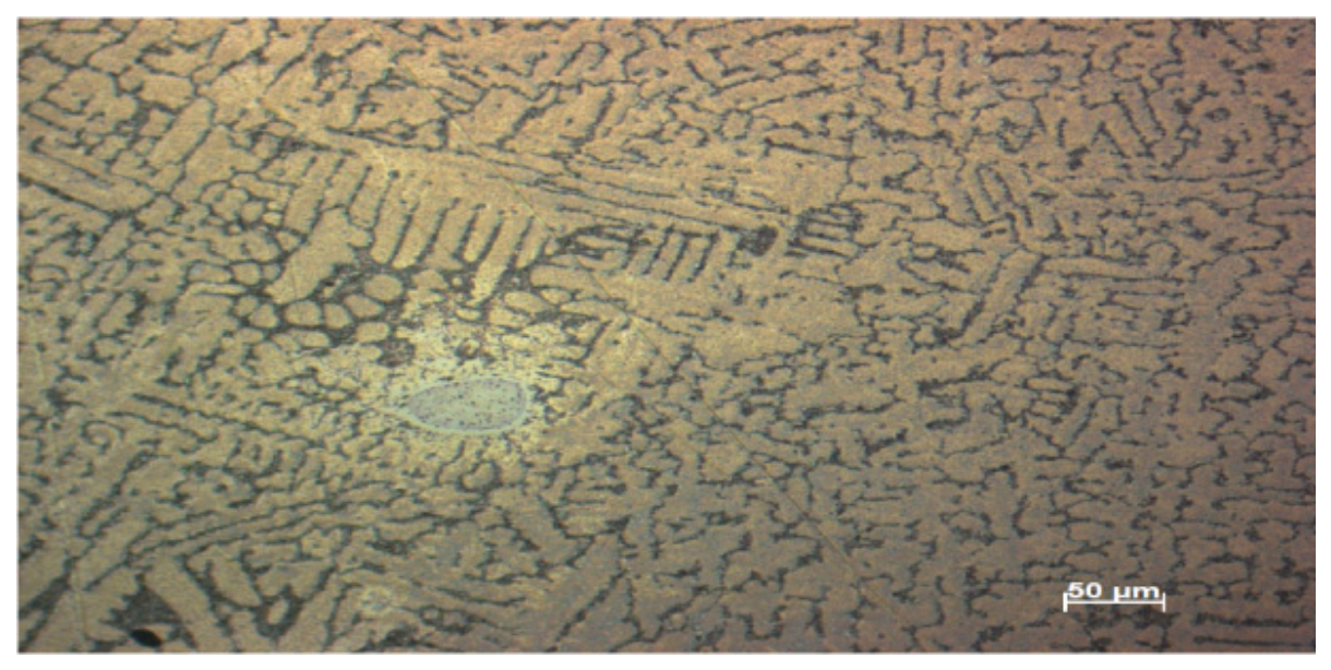
Figure 6 shows the observed intermetallic carbides that had formed on the cobalt basis. They are making the composite harder and are increasing the plasticity in a defined direction [15]. Also, WC particles embedded in the matrix are detected, which have kept their form and have not melted during the deposition. WC particles are randomly scattered and are sunk close to the intermediate zone between the base material and the applied hardfacing layer. Microstructural inhomogeneity was detected due to the combination of three individual materials: the base of X5CrNi18-10, Stellite 6, and WC. But in an extremely hot environment above 800 °C due to the cobalt matrix, this structure is expected to behave with more durability due to the higher melting point and more stable crystalline lattice than the base stainless steel.

3.2. Hardness/Young’s Modulus

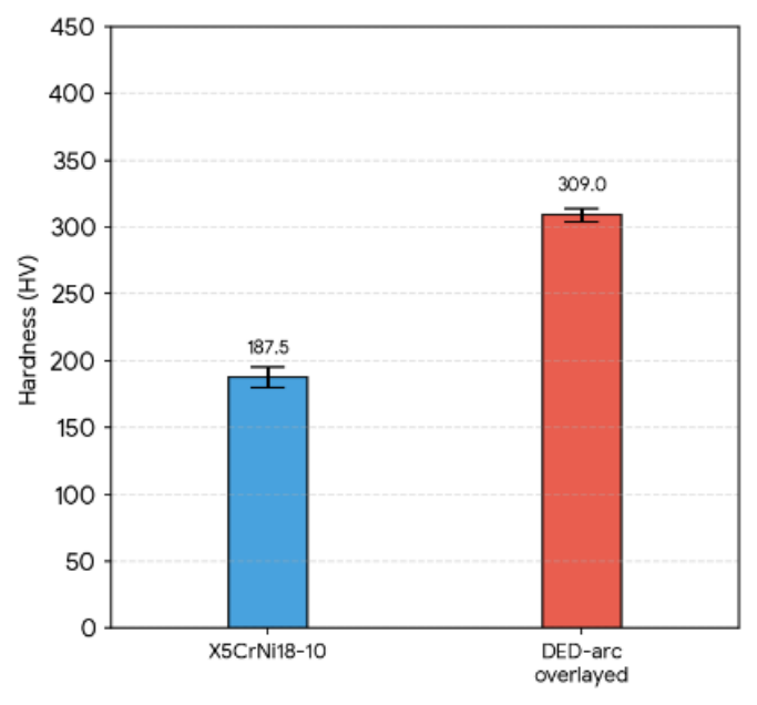
The work conditions for obtaining the basic hardness values and the Young’s modulus are according to the standards set in ISO 6507. The corresponding indentation load–depth curves are calculated after taking the load and displacement values of the indenter. After that, the statistical data of hardness/Young’s modulus are calculated from the unloading part of those curves. For the achieved harder layer, a general representative value HV = 309 is obtained (characterizing the greater Stellite 6 content) [15].
Microhardness measurement follows the Vickers method—Figure 7. The average values of the measurements are reported.
The DED-arc process successfully enhanced material surface properties, with mechanical testing showing a significant increase in hardness compared to the base X5CrNi18-10 substrate. A representative value of HV = 309 was achieved for the harder layer, directly attributed to higher Stellite 6 content and validated through statistical analysis of load–depth curves. On Figure 8 can be seen the hardness comparison.

3.3. Scratch Test

Micromechanical tests with UMT-2 (Bruker-CETR) are aimed at scratch adhesion and delamination of coatings (for coatings on different materials). Precise measurement of friction force, scratch depth, and critical delamination load through contact acoustic emission and contact electrical resistance sensors was done.
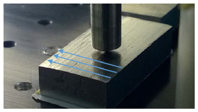
Direction and position of scratching with the micro-scratcher, combined with acoustic emission and Electrical Contact Resistances sensors, are seen in Figure 9.
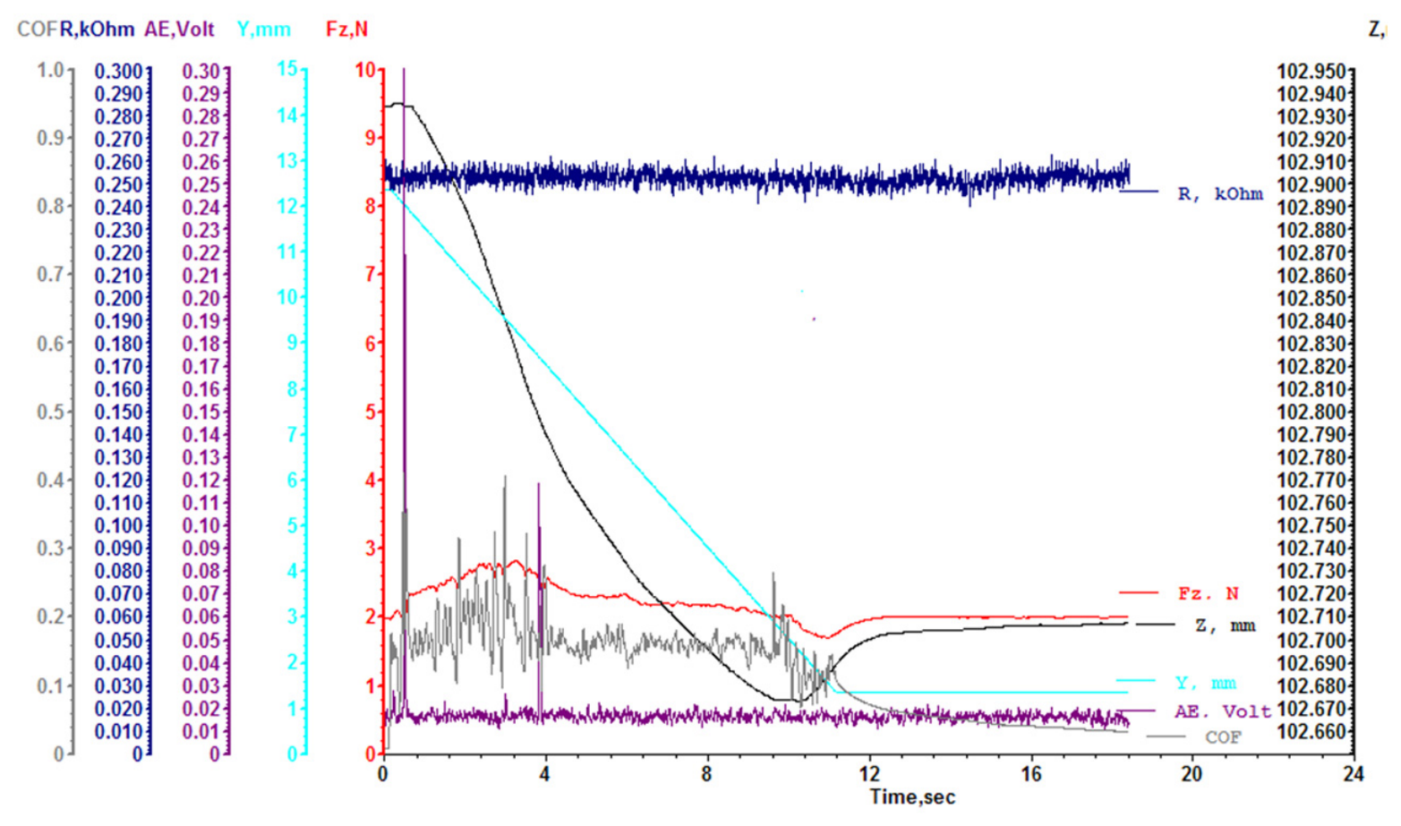
First, the samples are prepared for testing in a standard slurry abrasively environment/according to ASTM G75-01 [20]. Then, the special micro-mechanical tests with UMT-2 (Bruker-CETR) are carried out and indicate important information about the tribological characteristics of the new composite. For the sample tested, more detailed information for the detected time-scratching distance is given in Figure 10. While the contact electrical resistance is showing relatively constant values in the zone 0.240–0.260 kOhm, the acoustic emission has two very distinct peaks reaching correspondingly 0.30 V and 0.12 V. This could be interpreted by passing through the hard WC, while within Stellite 6, it generally keeps very low values, not exceeding 0.03 V. The obtained coefficient of friction values are strongly dependent on the surface roughness. In the extreme operational environment of thermal reactors, burner nozzles are subjected to a synergistic degradation process involving high-velocity particulate erosion, aggressive chemical corrosion, and severe thermal cycling. The longevity of these components is a critical economic driver; premature failure necessitates frequent unscheduled maintenance, resulting in substantial production losses and increased lifecycle costs. Strategic material selection and advanced fabrication methodologies are therefore essential to mitigate these risks.
The findings by Ortiz-Cañavate et al. [21] demonstrate that Directed Energy Deposition powder-based technology produces a finer microstructure and higher hardness compared to other metal Additive Manufacturing technologies (such as laser Powder Bed Fusion and binder jetting technology) for the production of automotive sealant nozzles. It is consistent with the results of the present study and proves the applicability of the chosen DED-arc technology for manufacturing thermal reactors and burner nozzles.

4. Conclusions

Three types of methods for the production of nozzles are discussed, with an observation of the characteristics of the DED-arc method, in order to perform a cost-effective replacement of worn-out parts. Before manufacturing, the corresponding characteristics of the coating composite are measured/evaluated: microstructure, hardness, and resistance to the environment. Due to the actual testing condition, it is concluded that the DED-arc is suitable as a method for the production of nozzles. Furthermore, the manufactured overlay exhibits excellent thermal stability, maintaining structural integrity under operational temperature cycles. Acoustic emission (AE) testing confirmed the absence of internal defects, such as micro-cracking or delamination, verifying the high quality of the metallurgical bond. These findings, combined with the established hardness profile, reinforce the reliability of DED-arc as a robust manufacturing technique for high-performance nozzles.

Funding

This research was funded by the European Regional Development Fund under the Operational Program “Scientific Research, Innovation and Digitization for Smart Transformation 2021–2027”, Project CoC “Smart Mechatronics, Eco- and Energy Saving Systems and Technologies”, BG16RFPR002-1.014-0005.

Institutional Review Board Statement

Not applicable.

Informed Consent Statement

Not applicable.

Data Availability Statement

The data is contained within the article.

Acknowledgments

The author would like to express gratitude to Technical University—Sofia, branch Plovdiv, University “Prof. Dr. Assen Zlatarov” Burgas, Bulgaria, Technischen Universität Chemnitz, Germany, and Open Laboratory on Experimental Micro and Nano Mechanics (OLEM), Bulgaria.

Conflicts of Interest

The author declares no conflicts of interest.

References

  1. ISO/ASTM 52900:2022; BDS EN Additive Manufacturing—General Principles—Fundamentals and Vocabulary. BSI: Sofia, Bulgaria, 2022.
  2. Piscopo, G.; Iuliano, L. Current research and industrial application of laser powder directed energy deposition. Int. J. Adv. Manuf. Technol. 2022, 119, 6893–6917. [Google Scholar] [CrossRef] [Scilit]
  3. Widener, C.; Ozdemir, O.; Carter, M. Structural repair using cold spray technology for enhanced sustainability of high value assets. Procedia Manuf. 2018, 21, 361–368. [Google Scholar] [CrossRef] [Scilit]
  4. Saboori, A.; Aversa, A.; Marchese, G.; Biamino, S.; Lombardi, M.; Fino, P. Application of Directed Energy Deposition-Based Additive Manufacturing in Repair. Appl. Sci. 2019, 9, 3316. [Google Scholar] [CrossRef] [Scilit]
  5. Keshavarz, M.; Gontcharov, A.; Lowden, P.; Chan, A.; Kulkarni, D.; Brochu, M. Turbine Blade Tip Repair by Laser Directed Energy Deposition Additive Manufacturing Using a Rene 142–MERL 72 Powder Blend. J. Manuf. Mater. Process. 2021, 5, 21. [Google Scholar] [CrossRef] [Scilit]
  6. Sales-Contini, R.d.C.M.; Pedroso, A.F.V.; Leitão, P.; Lucas, R.R.; Campilho, R.D.S.G.; Pinto, A.G.; Regattieri, C.R. Innovative Approaches to Enhance Thermal Efficiency and Reduce Sprue Backflow in Zamak Hot Chamber Injection Moulding. J. Mech. Eng. Manuf. 2025, 1, 4. [Google Scholar] [CrossRef] [Scilit]
  7. ISO 17296-2:2014; Additive Manufacturing—General Principles—Part 2: Overview of Process Categories and Feedstock. ISO: Geneva, Switzerland, 2014.
  8. Liu, Y.; Liu, X.; Lu, J.; Luo, K.; Zhang, Z.; Lu, H.; Zhang, H.; Xu, X.; Wang, Y.; Zhou, S. Post-treatment technologies for high-speed additive manufacturing: Status, challenge and tendency. J. Mater. Res. Technol. 2024, 30, 1057–1082. [Google Scholar] [CrossRef] [Scilit]
  9. Czán, A.; Czánová, N.; Holubják, J.; Czánová, T.; Krišák, D.; Markovič, J. Comparison of Selective Laser Melting and Atomic Diffusion Additive Manufacturing Technologies: Evaluating Stainless Steel Materials in Terms of Accuracy and Key Performance Indicators. Transp. Res. Procedia 2026, 93, 502–509. [Google Scholar] [CrossRef] [Scilit]
  10. Gao, B.; Zhao, H.; Peng, L.; Sun, Z. A Review of Research Progress in Selective Laser Melting (SLM). Micromachines 2023, 14, 57. [Google Scholar] [PubMed]
  11. Casalino, G.; Karamimoghadam, M.; Contuzzi, N. Metal Wire Additive Manufacturing: A Comparison between Arc Laser and Laser/Arc Heat Sources. Inventions 2023, 8, 52. [Google Scholar] [CrossRef] [Scilit]
  12. Cho, K.T.; Nunez, L.; Shelton, J.; Sciammarella, F. Investigation of Effect of Processing Parameters for Direct Energy Deposition Additive Manufacturing Technologies. J. Manuf. Mater. Process. 2023, 7, 105. [Google Scholar] [CrossRef] [Scilit]
  13. GOST 5632-2014; Alloy Steels and High-Alloy Corrosion-Resistant, Heat-Resistant and Creep-Resisting Steels. Grades. Euroasian Council for Standardization, Metrology and Certification: Minsk, Belarus, 2015.
  14. Rakhadilov, B.; Magazov, N.; Kakimzhanov, D.; Apsezhanova, A.; Molbossynov, Y.; Kengesbekov, A. Influence of Spraying Process Parameters on the Characteristics of Steel Coatings Produced by Arc Spraying Method. Coatings 2024, 14, 1145. [Google Scholar] [CrossRef] [Scilit]
  15. Boshnakova, S.; Markovska, I.; Rusev, D. Tribological Behavior of WC Particles Reinforced Surface Metal Matrix Composites Produced by Plasma Melt Injection. In Proceedings of the 4th International Conference on Water, Energy and Environment (ICWEE), Burgas, Bulgaria, 1–3 June 2016. [Google Scholar]
  16. Vempati, S.; Riss, F.; Schlemmer, D.; Aourdou, A.; Vidal, M.J.T.; Shynkarenko, O.; Casal, A.J.Y. Comparative Microstructural and Mechanical Assessment of Wire vs. Powder Laser-DED (AISI 316L). Metals 2026, 16, 400. [Google Scholar] [CrossRef] [Scilit]
  17. Meiyan, L.; Yong, W.; Bin, H.; Weimin, Z.; Tao, H. Microstructure and properties of high chrome steel roller after laser surface melting. Appl. Surf. Sci. 2009, 255, 7574–7579. [Google Scholar] [CrossRef] [Scilit]
  18. Liu, A.; Guo, M.; Hu, H.L. Distribution and dissolution of WC particles in surface metal matrix composites produced by plasma melt injection. Surf. Eng. 2010, 26, 623–628. [Google Scholar] [CrossRef] [Scilit]
  19. EN ISO 6507-1:2018; Metallic Materials—Vickers Hardness Test—Part 1: Test Method. ISO: Geneva, Switzerland, 2018.
  20. ASTM G75-01; Standard Test Method for Determination of Slurry Abrasivity (Miller Number) and Slurry Abrasion Response of Materials (SAR Number). ASTM International: West Conshohocken, PA, USA, 2001.
  21. Ortiz-Cañavate, J.; Ferrandiz, S.; Bloem, C.A.; Igual, J.; Blasco, J.R. A Detailed Properties Comparison of an Automotive Sealant Nozzle Produced Using Three Metal Additive Manufacturing Technologies. Materials 2024, 17, 3637. [Google Scholar] [CrossRef] [Scilit] [PubMed]
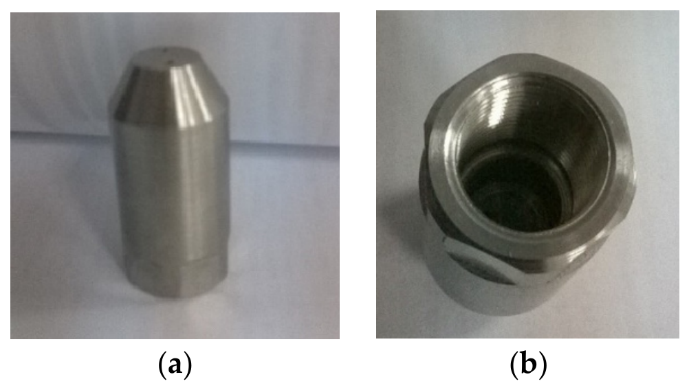
Figure 1. General view of the nozzles (a) front view (b) view from above.
Engproc 150 00068 g001
Figure 2. Nozzles after continuous operation.
Engproc 150 00068 g002
Figure 3. AM (SLM) produced burner’s nozzles (a) nozzle showing the inside distribution channels (b) complete assembly with the cup.
Engproc 150 00068 g003
Figure 4. Schematic drawing of the burner’s nozzles. Dimensions marked with an asterisk (*) are for reference only.
Engproc 150 00068 g004
Figure 5. DED-arc sample for the structure of the burner’s nozzles.
Engproc 150 00068 g005
Figure 6. Microstructure.
Engproc 150 00068 g006
Figure 7. Vickers Hardness calculation curve-successive microindentations, (a) corresponding loading with depth achieved curves, (b) plotted values of the Hardness/Young’s modulus with the statistical calculations within the microindenter software (version 2.15).
Engproc 150 00068 g007
Figure 8. Comparison of Vickers Hardness of bare and DED-arc overlayed samples.
Engproc 150 00068 g008
Figure 9. Direction and position of scratching with the micro-scratcher with blue arrows showing the direction of scratching.
Engproc 150 00068 g009
Figure 10. Microscratching with Force Fz = 2 N, constant 11 mm scratching path.
Engproc 150 00068 g010
Table 1. Comparison of applicable techniques.
FeatureSLM (Selective Laser Melting)DED-Arc (Powder Plasma Arc DED)TSAM (Thermal Spray AM)
CategoryPowder Bed Fusion (PBF)Directed Energy Deposition (DED)Thermal Spray/Kinetic
Relative CostHighestModerateLowest
Structural IntegrityMonolithic/Fully Dense (>99.8%)Near-Fully Dense
(98.5–99.5%)
Layered/Porous
(90–98%)
Geometric Accuracy±0.05–0.1 mm±0.5–1.0 mm±1.0–3.0 mm
Build SpeedSlow (Fine layers)High (Fast deposition)Very High
ComplexityExtremely high (Internal channels)Moderate (Geometric restoration)Low (Mainly surface/volume)
Table 2. Chemical composition of base metal.
Chemical Composition % of Steel X15CrNiSi25-21
CSiMnNiPSCrN
<0.21.5–2.5<219–22<0.045<0.01524–26<0.11
Table 3. The chemical compositions of the stainless steel substrate.
% Content of Elements in X5CrNi18-10
CSiMnPSCrNiFe
0.701.002.000.0450.01518.509.00rest
Table 4. The chemical contents of elements in Stellite 6.
% Content of Elements in Stellite 6
CoCrWCNiMoFeSiOthers
Bal.28.54.61.2<2.0<1.0<2.0<2.0<1.0
Disclaimer/Publisher’s Note: The statements, opinions and data contained in all publications are solely those of the individual author(s) and contributor(s) and not of MDPI and/or the editor(s). MDPI and/or the editor(s) disclaim responsibility for any injury to people or property resulting from any ideas, methods, instructions or products referred to in the content.