1. Introduction
The extensive use of fossil fuels (coal and oil) was predetermined by rapid industrial development. This exploitation causes severe adverse effects—environmental pollution and greenhouse gas emissions. In addition to the adverse effects of pollution on the environment and human health, it has contributed to long-term global warming. Because of this, humanity faces extreme climatic conditions much more often—excessive heat or cold, drought, floods, storms, etc. Moreover, the most essential and widely used fossil fuels—coal and oil—are non-renewable, and their reserves will ultimately be exhausted. Given the ever-increasing demand for energy and the challenges of meeting it through fossil fuels, the world is increasingly turning to renewable energy sources, especially those that produce little or no emissions and, therefore, do not contribute to pollution or greenhouse gas emissions. The most effective measure is to focus on renewable energy sources that produce little to no emissions and therefore do not contribute to the greenhouse effect [
1].
A type of renewable energy source is hydropower. The amount of electricity that conventional hydroelectric plants can generate depends on annual rainfall and the amount of water, both of which flow into the estuarine basins (or reservoirs) from which Bulgaria draws most of its hydropower. Typically, hydropower is described by the energy generated by the power plant (installed capacity measured in kilowatts or megawatts) or by the hydropower category (conventional, micro-hydro, low-head, or hydrokinetic) into which the installed capacity falls. Conventional hydroelectric power plants (HPPs) use a higher head than other technologies, such as hydrokinetic systems. Micro-hydro systems can exploit lower heads and/or flows in ways that large systems cannot [
2].
Hydrokinetic systems can be categorized as fluvial (river) or tidal. River systems use energy mainly from the unidirectional flow of surface water. Low-pressure turbines are used, and although the source of energy is the river’s height difference, these turbines are of a different design (due to the low head) [
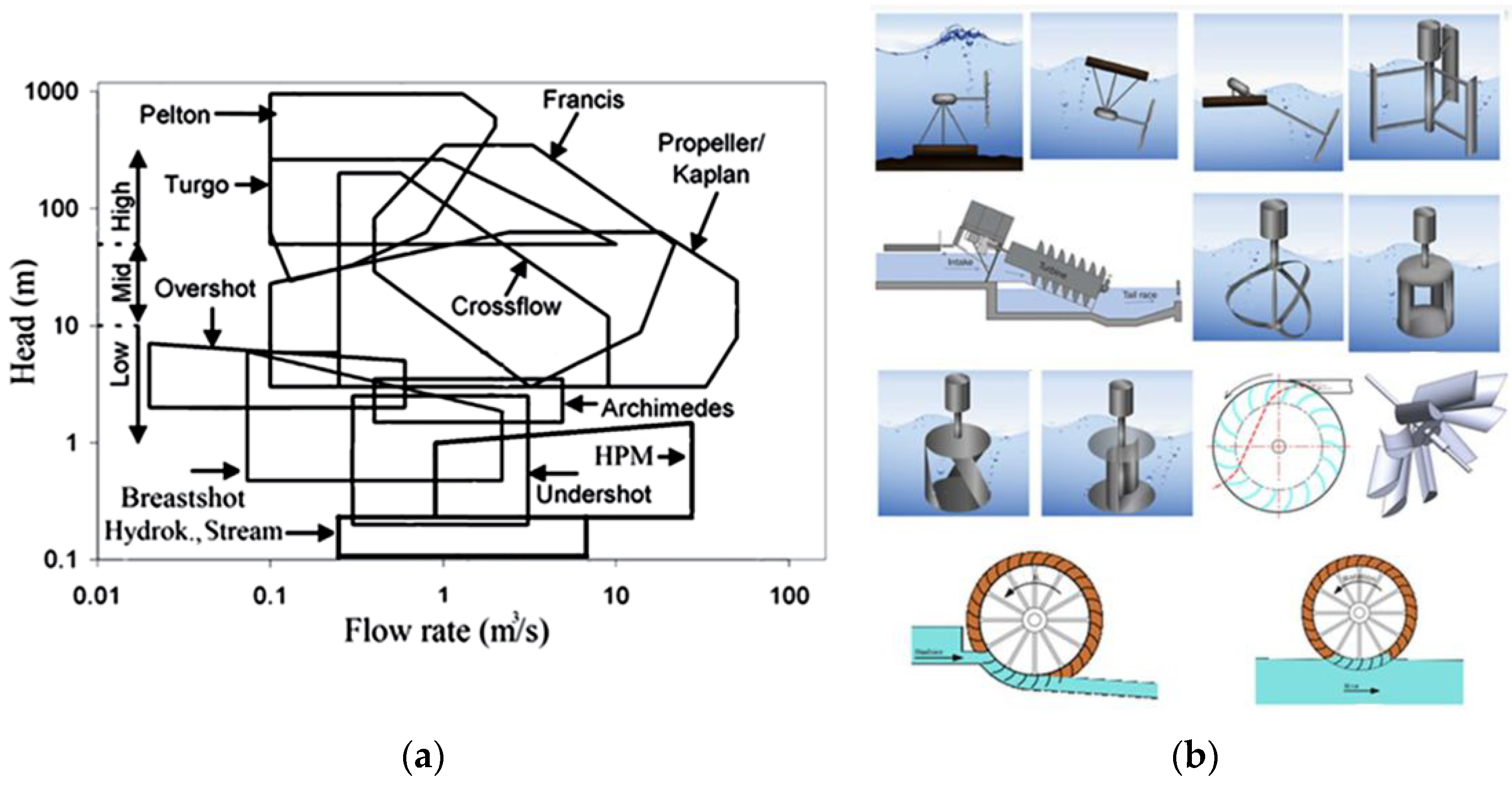
3]. Such systems do not require the construction of dams; they do not divert water from the natural system, and they can generate power from very low heads compared to conventional hydropower systems. The applicability of the various turbine and wheel designs depends on the head and the available flow rate. A summary of the applicability of the various systems with respect to these two parameters is shown in
Figure 1a [
4]. Along with the popular Pelton, Francis, and Kaplan turbines operating at high and medium head values, other low-voltage turbines are also used. The diagram also covers three types of wheels, of which two—the low-pressure (undershot) and the zero-pressure water wheel (stream)—are the subject of current research as components of hydrokinetic systems.
Hydrokinetic systems are hydro-mechanical energy converters that convert the kinetic energy of pressure-free or low-pressure currents into other usable forms of energy. Hydrokinetic systems are those that use turbines and non-conventional power generation systems. Both types of systems use the energy from the unidirectional movement of water, with current developments and research mainly focused on turbine-based systems [
5]. The developed non-conventional concepts, for the most part, are in the intensive development stage and need further research, development, and experimental work before they can be implemented [
5]. Principal schematics of hydrokinetic systems are shown in
Figure 1b.
Different designs have different efficiencies and applicability. Available literature on the effectiveness of the structures shows wide variation, ranging from 20% to 80% [
6]. Three models of hydrokinetic systems could emerge as the most effective: the Bánki–Michell–Ossberger (BMO) turbine (crossflow), an axial turbine attached to the bottom, and an undershot water wheel.
This study focuses on crossflow turbines, also known as BMO-type turbines.
1.1. Crossflow Turbines
Crossflow turbines, or BMO turbines, are a very efficient and economical choice that offers a strong price-to-performance ratio. The crossflow water turbine is used for pressures H = 2 ÷ 200 m, but its power is usually limited to 1000 kW, which corresponds to relatively low efficiency values (up to 85%). In individual cases, the power of turbines of this type can reach up to 3000 kW (for example, the turbines of Ossberger GmbH + Co, Weissenburg, Germany) [
2]. However, this type of turbine has several advantages for the specific requirements of small-power water turbines, making it competitive in the market. The most important of these advantages are:
Extremely simple and technological construction (without special requirements for the machine equipment of the manufacturer);
Relatively high efficiency values, in a wide range of modes;
Provides good opportunities for manual and automatic adjustment;
Has a low cost;
Is characterized by a high degree of unification of components and details (a very significant advantage for the hydropower equipment of small hydropower plants).
The principal scheme of the Bánki–Michell–Ossberger turbine is shown in
Figure 2, together with a typical design with a horizontal axis [
7].
1.2. Virtual Prototyping
Most existing installations of crossflow turbines use a horizontal-axis design [
8,
9]. This study aims to examine the concept of crossflow with a vertical axis by comparing it with the horizontal-axis type. It is performed using virtual prototyping technology.
Virtual prototyping is a useful tool for comparing concepts, as it provides detailed information on the parameters of examined variants that would otherwise require time and resources to evaluate through physical prototyping [
10,
11,
12]. It involves various numerical analysis techniques that allow not only the simulation of the ongoing process but also its optimization [
13,
14]. The ability to follow up on internal parameters, for instance, fluid flow or pressure distribution across a cross-sectional plane, is another major feature of this technology [
15]. This study uses computational fluid dynamics (CFDs) analysis, in which the turbine rotation is modeled using movable-mesh technology. It also presents mixing and interaction of two phases: liquid (water) and gas (air). These specifics require more computational time and resources but are mandatory for representing the ongoing physical process.
2. Materials and Methods
Two virtual prototypes of crossflow turbines are to be examined: a 2D horizontal-axis turbine model and a 3D vertical-axis turbine model. The difference in the method is due to the design specifics that allow using a 2D model for the horizontal-axis turbine, with no transverse effects requiring 3D modeling.
2.1. Method and Virtual Prototype for Assessment of Crossflow Turbine with Horizontal Axis
A virtual prototype is built using a sample design space, whose sizes are determined for a river application. The turbine diameter is 5.6 m, and its width is 24 m. The model and applied boundary conditions are shown in
Figure 3. The rotating mesh contains the turbine and its blades. It connects to a tiny ring that is static to transfer fluid flow parameters to the surrounding environment.
The mesh is generated primarily from simple 2D quadrilateral elements. The most important feature of the mesh is the element quality. The maximal skewness for this model is less than 0.6, which allows simulation of a dynamic process as the one examined. The mesh is presented in the figure below, including general and local section views.
Figure 3.
2D virtual prototype of crossflow turbine with horizontal axis.
Figure 3.
2D virtual prototype of crossflow turbine with horizontal axis.
2.2. Method and Virtual Prototype for Assessment of Crossflow Turbine with Vertical Axis
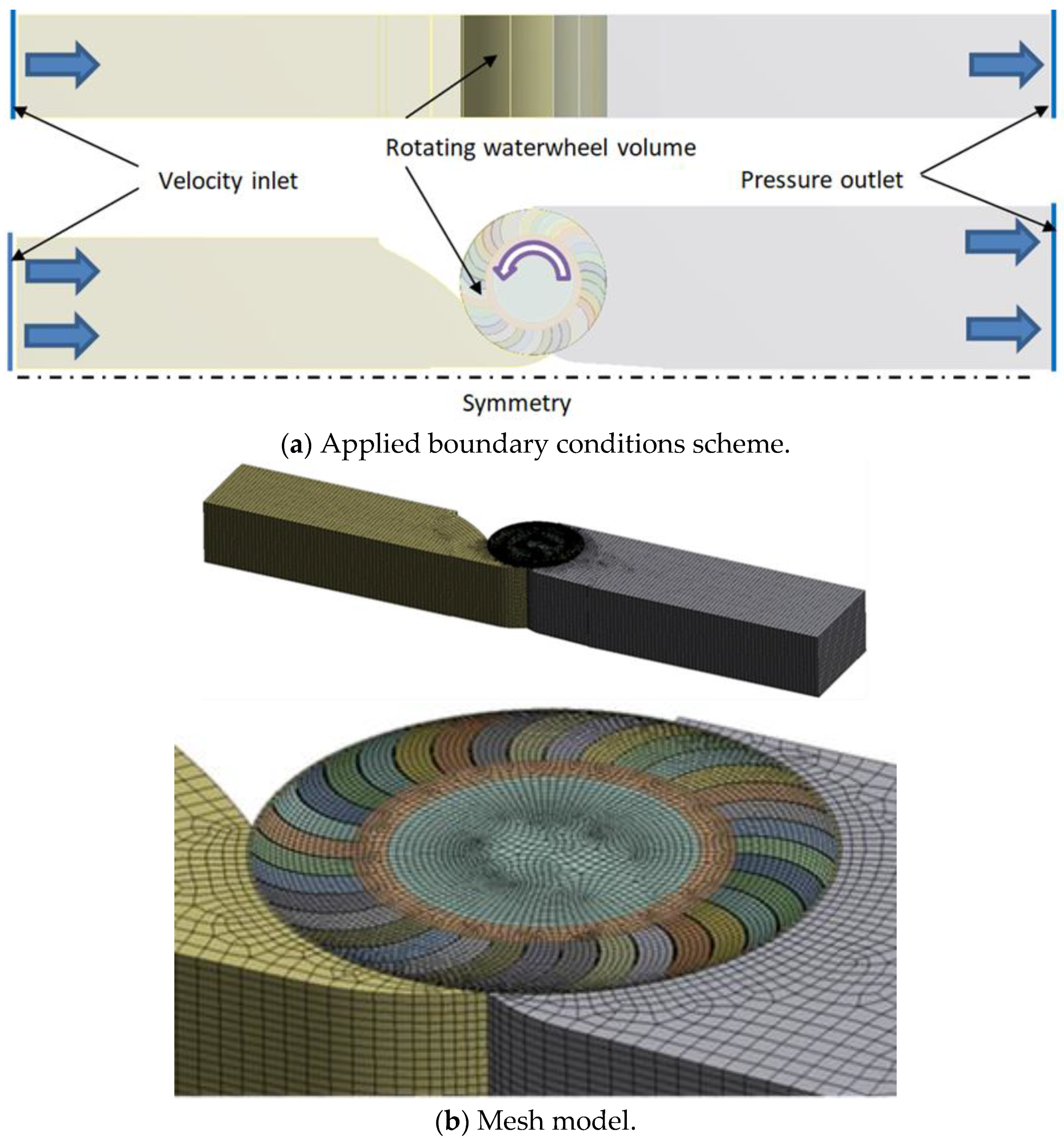
The vertical-axis prototype has similar dimensions and is applied in the same design space, again predetermined by the river site. Two turbines are modeled, with a 5.6 m external diameter. The design has 35 blades and a height of 4 m. A simulation model is built based on a virtual prototype. Further simulations of a crossflow turbine are performed, including 3D modeling.
This model uses the available design transverse symmetry and includes only one turbine. This is included in the model via the applied symmetry, as shown in
Figure 4a. A 3D numerical model is presented in
Figure 4b to show the mesh density and characteristics. It contains approximately 372,000 cells and 412,000 nodes.
The crossflow turbine volume is defined as a dynamic, rotating mesh that interfaces with the near fluid. Its angular velocity is defined for each analysis separately.
3. Results
3.1. Results for Crossflow Turbine with Horizontal Axis
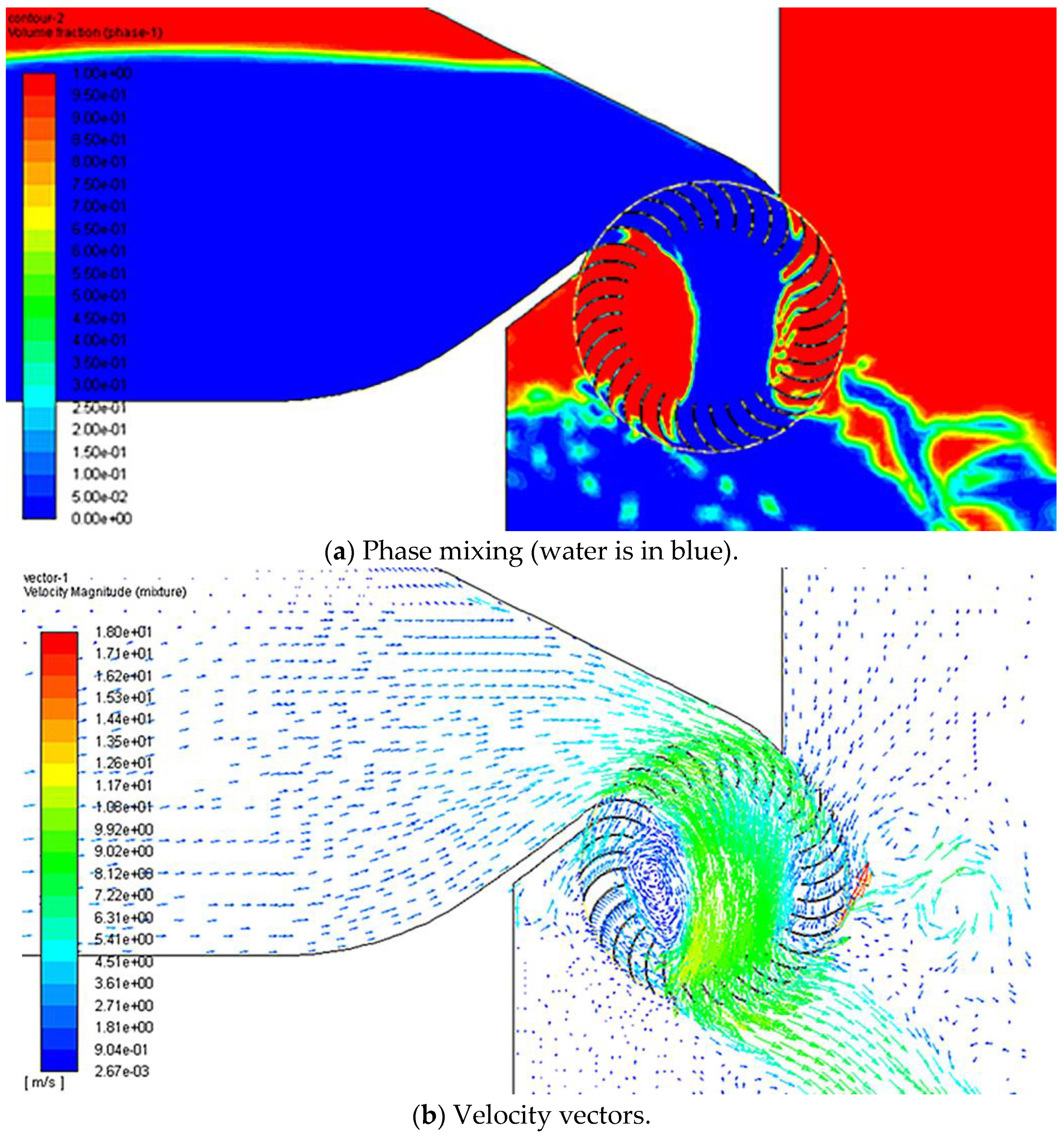
Several simulations are run using different turbine rotation values at three fluid flow rates—400, 250, and 150 m
3/s. The simulation results are presented in general views, for illustration, in
Figure 5. These results are for 400 m
3/s of fluid flow and provide an overall view of water mixing, splashing, and their interactions with the blades.
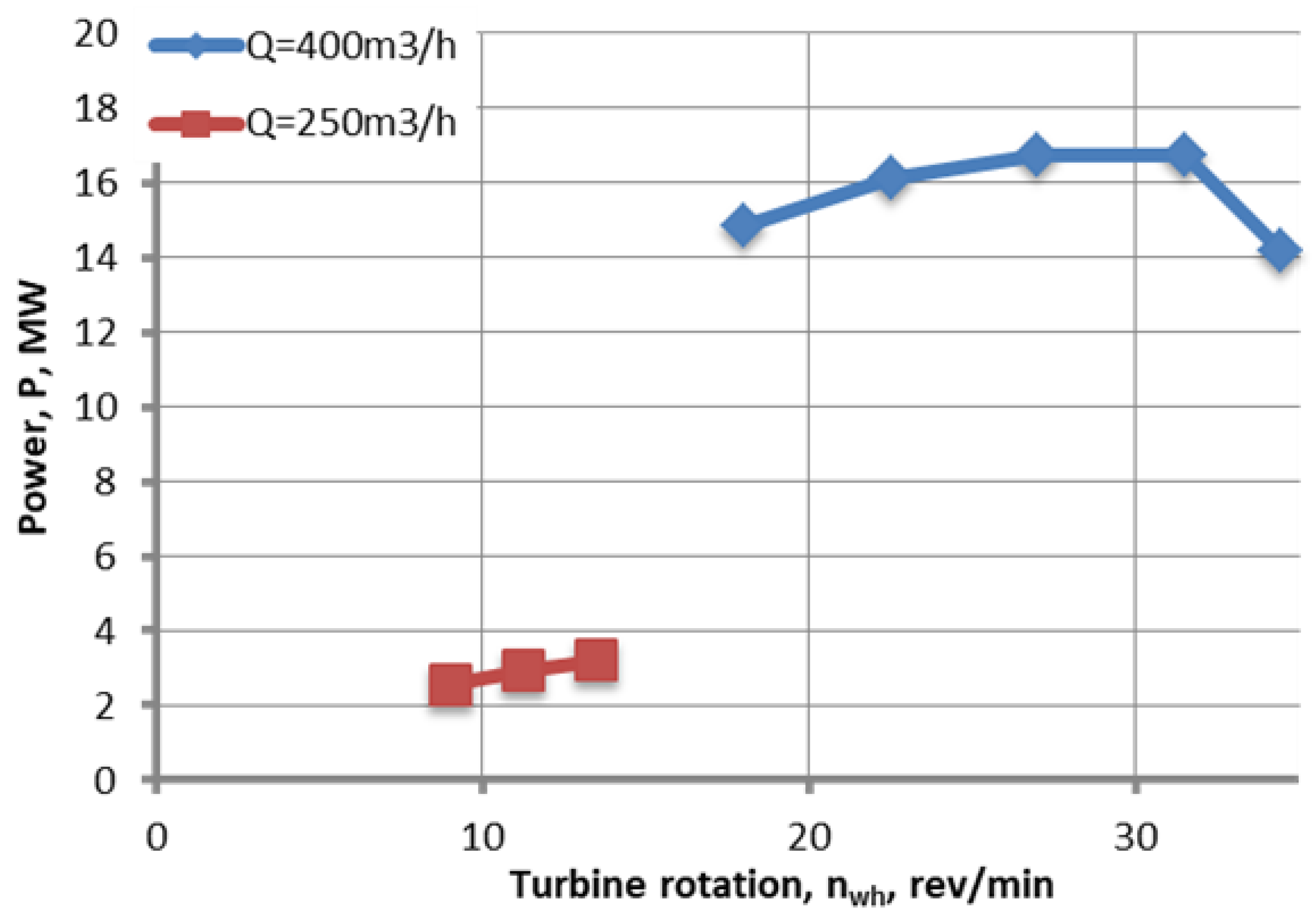
The results are summarized in
Figure 6, where fluid flow of 400 m
3/s is examined in higher level of detail. The other two fluid flows are checked at a point.
3.2. Results for Crossflow Turbine with Vertical Axis
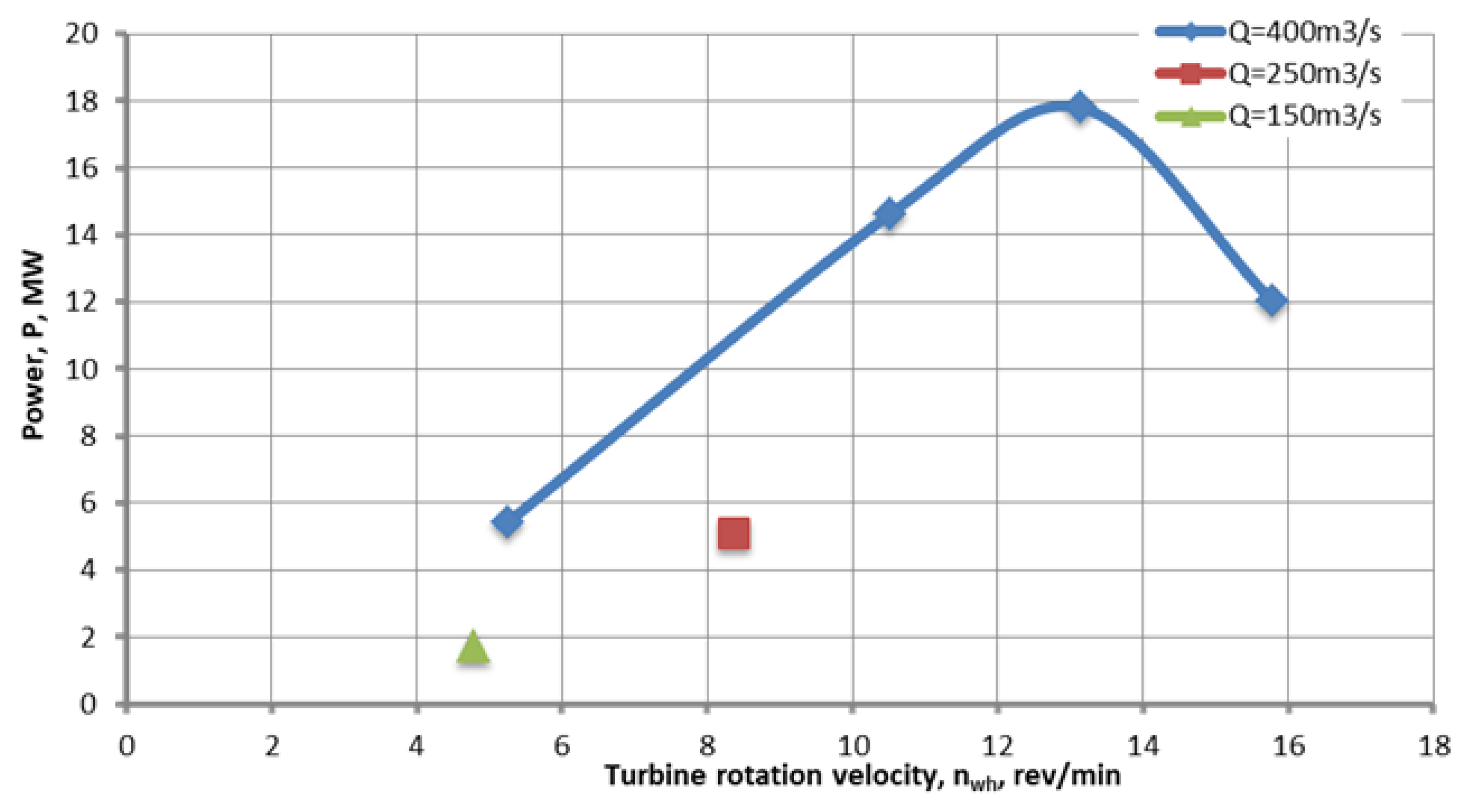
Several simulations are run to calculate the performance of both turbines at a water flow of 100 m3/s. This corresponds to 400 m3/s. The target is to follow turbine performance using three parameters: harvested energy, efficiency, and inlet pressure (needed head) as functions of turbine rotational velocity.
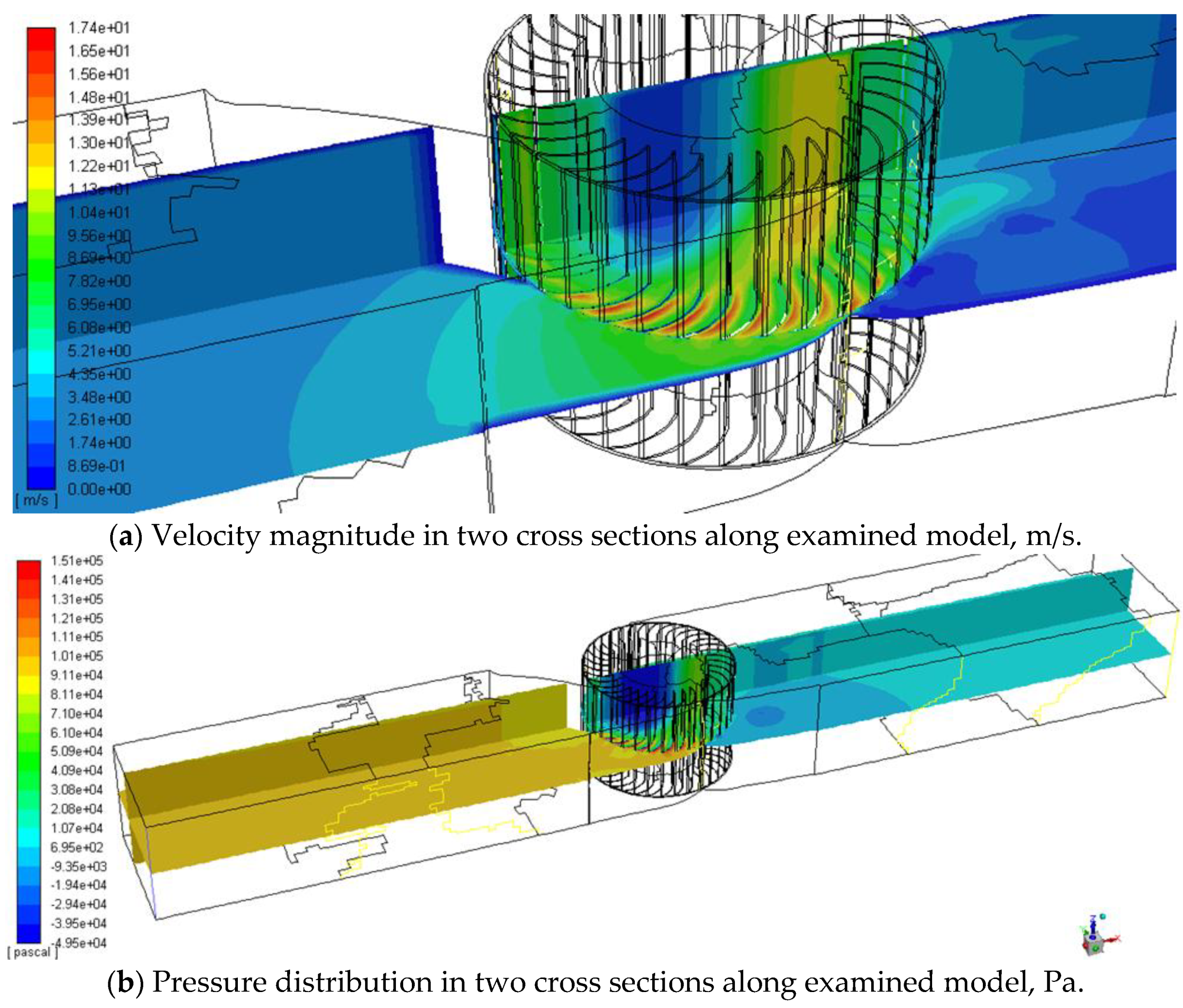
The results are initially presented as a velocity magnitude distribution field (
Figure 7a) and a total pressure distribution field (
Figure 7b).
All results correspond to a fluid flow rate of 400 m
3/s. Characteristics of the turbine, such as harvested energy, efficiency, and inlet pressure as functions of the rotational speed, are shown in
Figure 8.
Several comments could be made:
The crossflow turbine is more stable in a wider rotational speed range—it produces more than 5 MW in the range from 22.5 min−1 to 32 min−1;
Its efficiency decreases with increased rotational velocity, but harvested energy increases as well as required head;
A good solution is to operate at 22.5 min−1, with a power of nearly 5 MW and a requested head of about 6 m.
4. Discussion
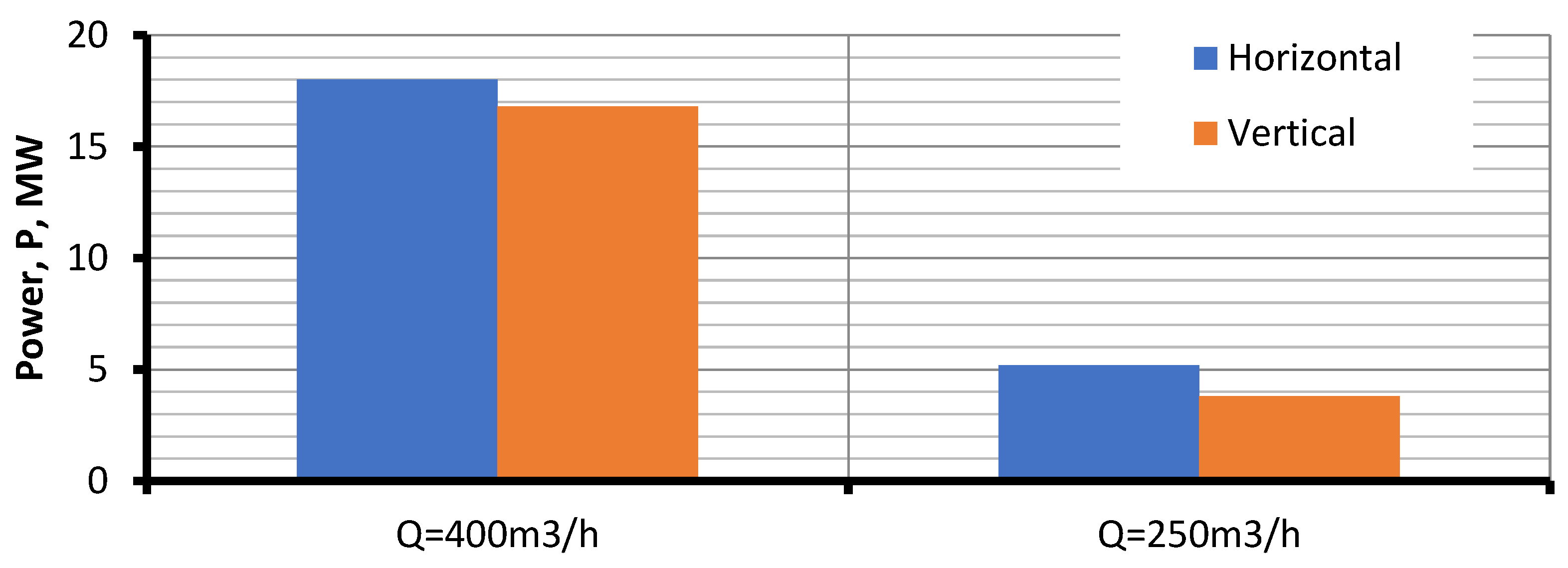
The results from the virtual prototyping of a crossflow turbine with horizontal and vertical axes are compared and analyzed primarily based on the generated power.
This comparison is shown in the graph in
Figure 9 for two fluid flows. Several comments could be outlined, based on this analysis:
The crossflow turbine with a horizontal axis shows similar, but higher, harvested power at both examined water flows.
A horizontal-axis turbine requires a certain head (minimum 1 m), which could be a barrier to further realization.
The vertical-axis concept is more compact.
The vertical-axis concept has more units.
A horizontal-axis turbine requires better sealing than a vertical-axis crossflow turbine.
5. Conclusions
The study demonstrates the applicability of virtual prototyping to deliver fast results for complex, expensive structures, such as crossflow turbines for installation at river sites. Several major comments could be formed concerning the examined crossflow turbine concepts and the performed study:
A possible solution for harvesting energy in open water channels is examined using virtual prototyping models.
Two concepts are developed for crossflow turbine applications, with horizontal and vertical axes.
Harvested power at different water flows is evaluated for both concurrent concept variants.
The horizontal-axis crossflow turbine shows slightly better results in terms of electrical power output.
An overall analysis of the obtained results and design parameters indicates that a crossflow turbine with a vertical axis is the better concept.
Further detailed characterization and design are scheduled.
This work is a good example of the practical application of numerical analysis and virtual prototyping and demonstrates a specific, complex field, such as computational fluid dynamics.
Author Contributions
Conceptualization, K.K. and G.T.; methodology, G.T. and K.K.; software, B.Z.; validation, G.T. and K.K.; formal analysis, B.Z.; investigation, K.K. and B.Z.; resources, B.Z.; data curation, B.Z.; writing—original draft preparation, K.K.; writing—review and editing, K.K.; visualization, B.Z.; supervision, G.T.; project administration, G.T. and B.Z.; funding acquisition, G.T. All authors have read and agreed to the published version of the manuscript.
Funding
This work was supported by the European Regional Development Fund under the “Research Innovation and Digitization for Smart Transformation” program 2021–2027 under the Project BG16RFPR002-1.014-0006 “National Centre of Excellence Mechatronics and Clean Technologies” and by the project KП-06-H67/8, “Development of a fluid-structural methodology for the study and modernization of HYDRAulic turbomachines, through the TECHnologies of virtual prototyping–HydraTech”.
Institutional Review Board Statement
Not applicable.
Informed Consent Statement
Not applicable.
Data Availability Statement
The data are contained within the article.
Conflicts of Interest
The authors declare no conflicts of interest.
Abbreviations
The following abbreviations are used in this manuscript:
| HPP | Hydroelectric power plant |
| BMO | Bánki–Michell–Ossberger |
| CFD | Computational Fluid Dynamics |
| 2D | Two-dimensional |
| 3D | Three-dimensional |
References
- Chica, E.; Rubio-Clemente, A. Design of Zero Head Turbines for Power Generation. In Renewable Hydropower Technologies; IntechOpen: London, UK, 2017; Volume 1, pp. 25–50. [Google Scholar]
- Obretenov, V. Optimisation of Cross-Flow Water Turbine; Technion City: Haifa, Izrael, 1996. [Google Scholar]
- Bedard, R.; Previsic, M.; Polagye, B.; Hagerman, G.; Casavant, A.; Tarbell, D. North Ameica Tidal In-Stream Energy Conversion Technology Feasibility Study. EPRI TP-008-NA. 2006. Available online: https://faculty.washington.edu/seidler/EPRI_06-10-06_Thomson_lecture.pdf (accessed on 20 July 2026).
- Quaranta, E. Stream water wheels as renewable energy supply in flowing water: Theoretical considerations, performance assessment and design recommendations. Energy Sustain. Dev. 2018, 45, 96–109. [Google Scholar] [CrossRef] [Scilit]
- Khan, M.; Bhuyan, G.; Iqbal, M.; Quaicoe, J. Hydrokinetic Energy Conversion Systems and Assessment of Horizontal and Vertical Axis Turbines for River and Ridal Applications: A Technology Status Review. Appl. Energy 2009, 2, 1823–1835. [Google Scholar] [CrossRef] [Scilit]
- Anurag, K.; Saini, R.P. Development of Hydrokinetic Power Generation System: A Review. Int. J. Eng. Sci. Adv. Technol. 2014, 4, 464–477. [Google Scholar]
- Sinagra, M.; Sammartano, V.; Aricòa, C.; Collura, A.; Tucciarelli, T. Cross-Flow turbine design for variable operating conditions. In Proceedings of the 12th International Conference on Computing and Control for the Water Industry, CCWI2013, Perugia, Italy, 2–5 September 2013. [Google Scholar]
- Tian, W.; Mao, Z.; Ding, H. Design, test and numerical simulation of a low-speed horizontal axis. Int. J. Nav. Archit. Ocean Eng. 2018, 10, 782–793. [Google Scholar] [CrossRef] [Scilit]
- Adhikari, R.; Wood, D. The Design of High Efficiency Crossflow Hydro. Energies 2018, 11, 353–362. [Google Scholar] [CrossRef] [Scilit]
- Coutts, E.R.; Pugsley, C. Physical versus Virtual Prototyping and Their Effect on Design Solutions. In Proceedings of the Fifth International Conference on Design Creativity-ICDC2018, Bath, UK, 31 January–2 February 2018. [Google Scholar]
- Nedelchev, K.; Kralov, I.; Gieva, E.; Ruskova, I.; Nikolov, G. Acoustic barrier with energy harvesting. In Proceedings of the 2020 21st International Symposium on Electrical Apparatus and Technologies, SIELA 2020-Proceedings, Bourgas, Bulgaria, 3–6 June 2020. [Google Scholar]
- Romansky, R.P.; Hinov, N.L. Deterministic and Stochastic Approaches in Computer Modeling and Simulation; IGI Global: Hershey, PA, USA, 2023. [Google Scholar]
- Malakov, I.; Zaharinov, V.; Tzenov, V. Size Ranges Optimization. Proc. Eng. 2015, 2, 791–800. [Google Scholar] [CrossRef] [Scilit]
- Malakov, I.; Zaharinov, V. Optimization of size ranges of technical products. Appl. Mech. Mater. 2016, 859, 194–203. [Google Scholar] [CrossRef] [Scilit]
- Todorov, G.D.; Kamberov, K.H. Black box/white box hybrid method for virtual prototyping validation of multiphysics simulations and testing. IOP Conf. Ser. Mater. Sci. Eng. 2020, 878, 29–36. [Google Scholar] [CrossRef] [Scilit]
| Disclaimer/Publisher’s Note: The statements, opinions and data contained in all publications are solely those of the individual author(s) and contributor(s) and not of MDPI and/or the editor(s). MDPI and/or the editor(s) disclaim responsibility for any injury to people or property resulting from any ideas, methods, instructions or products referred to in the content. |