Abstract
Our work consists of designing a dual-band planar antenna based on meta-materials for 5G applications. We propose a design approach consisting of a deposited patch antenna on an FR-4 type monolayer substrate placed above the CSRR cells based on the meta-materials working in millimeter wave. Thereafter, we will do a parametric study to extract the various parameters that influence its electromagnetic behavior. The studied and designed antenna aims to be used for 5G phone applications in the frequency band 3.3–3.8 GHz and Wi-Fi. The design is carried out by CST Microwave Studio software.
Keywords:
design; patch antenna; bi-band antenna; miniature antenna; meta-materials; 5G; Wi-Fi; CST Microwave Studio 1. Introduction
The commercial use of 5G has arrived to meet the growing demands for low latency, big capacity, and ubiquitous mobile access, and will play a key role in connecting and enabling services. 5G must address, in addition to an increase in traffic volume, the challenge of connecting billions of devices to heterogeneous service needs [1]. 5G networks are expected to supply a lot of improvements [2].
The antenna is an essential element in 5G networks; however, it always occupies a higher volume in the communication chain, making it difficult to implement in small areas. Its miniaturization has become essential for an optimal design. Many antenna miniaturization techniques exist, and all go through a compromise between size and performance (bandwidth and/or radiation yield) [3], such as charging by passive elements, short circuit application, slots insertion, and use of a dielectric substrate of very high permittivity and meta-materials, etc.
Most materials found in nature (e.g., dielectrics) have positive constitutive parameters (ε > 0 and μ > 0). For this reason, they are called doubly positive materials (DPS). Materials with negative permittivity and positive permeability (ε < 0 and μ > 0) are called epsilon-negative materials (ENG), whose characteristics are presented by plasmas at certain frequencies [4]. On the other hand, materials with positive permittivity and negative permeability (ε > 0 and μ < 0) are known as mu-negative materials (MNG), and ferrites exhibit this behavior at certain frequencies [5]. Materials that have negative constitutive parameters (ε < 0 and μ < 0) are called doubly negative materials (DNG), or meta-materials. Until now, these materials have not been found in nature and they are obtained artificially.
Meta-materials have attracted great attention in recent years due to their unusual electromagnetic properties and their ability to guide and control electromagnetic waves where natural materials cannot [6]. The meta-materials used in the antennas field offer advantages such as reduction in weight and bulk, which is beneficial for their integration into electronic systems such as telecommunications systems in general, and telephone systems for the fifth generation (5G) in particular. In addition, the use of the latter aims to improve its characteristics in terms of resonance frequency (to have multi-band structures or rejected bands) and to make them reconfigurable, as well as for improved bandwidth, gain, directivity, mutual coupling minimization in an antenna array, polarization, and radiation pattern [7,8,9].
2. Design of a Patch Antenna for 5G
The geometry of the initial antenna is shown in Figure 1. This structure consists of a radiating element with length Lp and width Wp, with notches, fed by a microstrip line. It is deposited on an FR-4 type dielectric substrate with dielectric permittivity εr = 4.3, of dimensions Ls and Ws and thickness h. The ground plane covers the substrate’s whole rear face. Table 1 gives the dimensions of the initial antenna with notches using the given equations in [10,11,12].
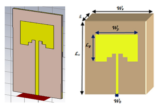
Figure 1.
Geometry of the initial antenna.

Table 1.
Dimensions of the initial antenna.
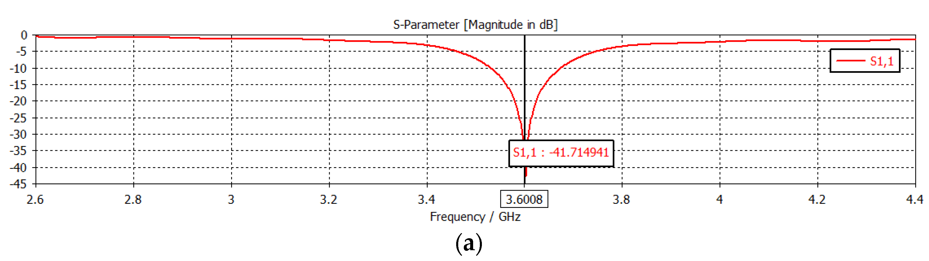
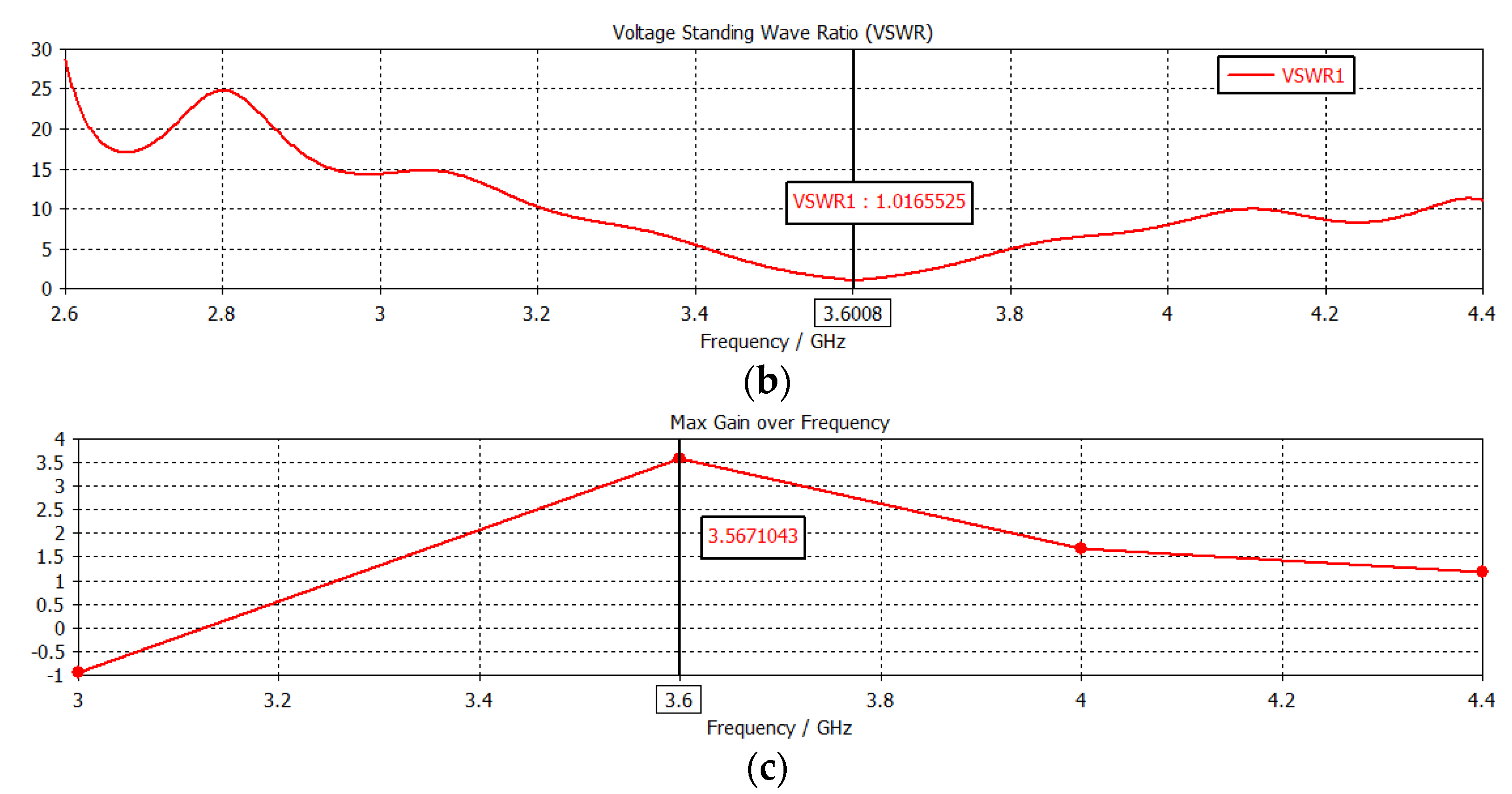
Figure 2a,b represents, respectively, the return loss, the stationary wave rate VSWR, and the gain of the initial antenna.
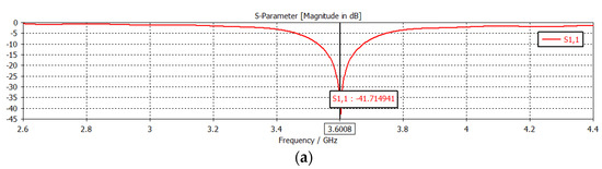
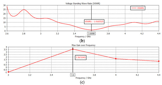
Figure 2.
(a) Return loss. (b) Stationary wave rate. (c) Antenna gain.
Figure 2a shows that the adaptation is well-realized since the return loss S11 attains a level close to −41.86 dB at the resonant frequency 3.6 GHz, so the reflection at the antenna input is zero. We have also presented the stationary wave rate, which we notice is between 1 and 2 in the theoretical frequency band 3.53–3.67 GHz, which shows a good impedance match between the antenna and the feed line. The bandwidth is order 3.88%. The antenna gain is around 3.567dB at the resonance frequency 3.6 GHz.
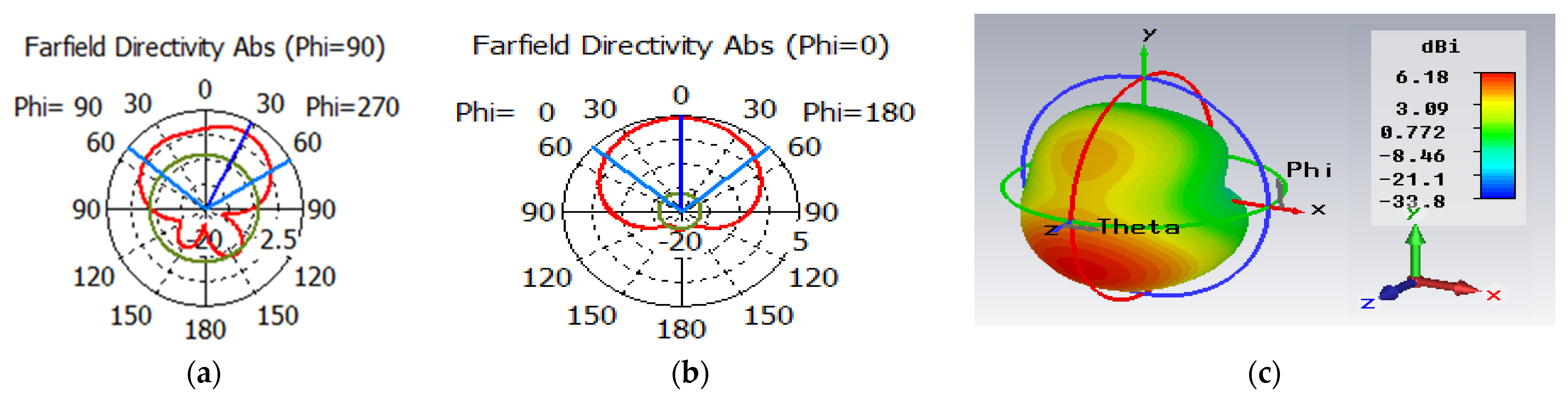
Figure 3a–c represents, respectively, the polar radiation patterns, in 2D and 3D, of the antenna at the resonant frequency 3.6 GHz.

Figure 3.
(a) Radiation pattern in 2D, plan H. (b) Radiation pattern in 2D, plan E. (c) Radiation pattern in 3D.
We notice that the exhibit antenna has almost omnidirectional radiation in the E-plane (φ = 0°) and in the H-plane (φ = 90°). These plots are verified on the radiation pattern plot in 3D.
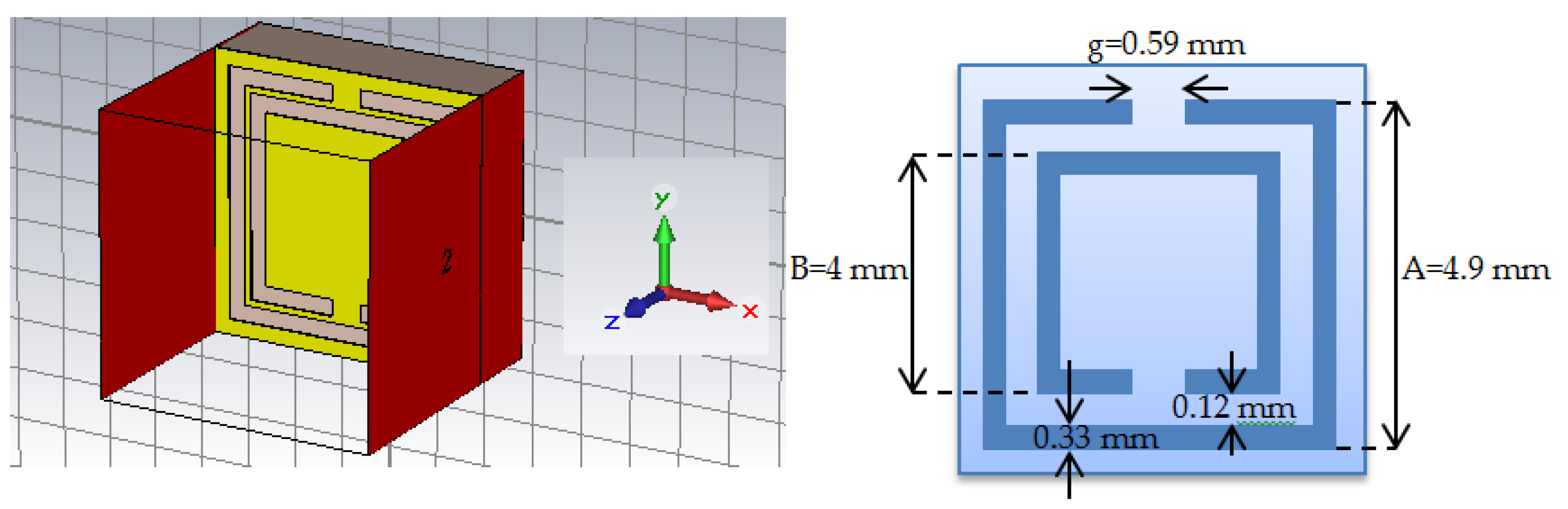
3. Design of the CSRR Cell for 5G
The two-dimensional periodic structure of a complementary split-ring resonator (RAFC) is shown in Figure 4. The CSRR (complementary split-ring resonator) is placed on a lossy FR-4 type substrate characterized by a permittivity of 4.3, with a thickness of 1.56 mm. For the studied square RAFC, the external slot ring’s external side is equal to (A = 4.9 mm), and the internal slot ring’s external side is equal to (B = 4 mm). The two rings are concentric and spaced at 0.12 mm. Each ring is 0.33 mm wide, with a cut in the side of each ring presenting a gap of g = 0.59 mm.
Figure 4.
CSRR cell at the resonant frequency 3.6 GHz.
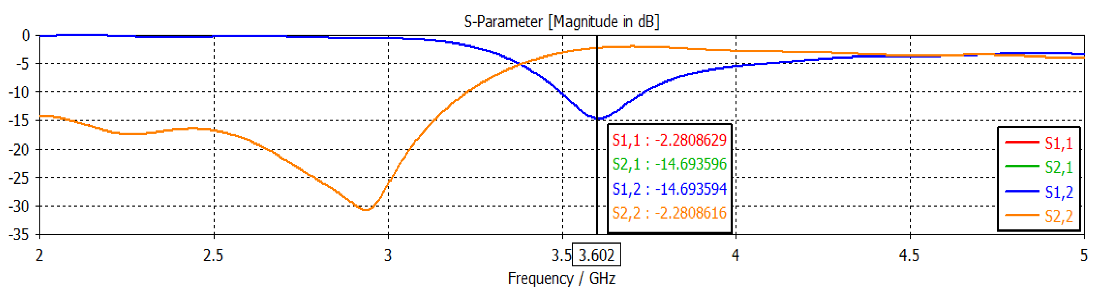
Figure 5 represents the modulus in dB of the return loss (S11) and transmission coefficient (S21) of the CSRR cell obtained by CST MWS software.

Figure 5.
Transmission coefficient and return loss of the CSRR cell.
From the presented results in Figure 5, it can be seen that:
- -
- The return loss S11 modulus presents a resonance at 3.602 GHz with a reflection of −2.28 dB.
- -
- The transmission coefficient S21 modulus goes down to a value of −14.69 dB at the resonant frequency 3.602 GHz.
4. Design of a Dual-Band Antenna Based on Meta-Materials
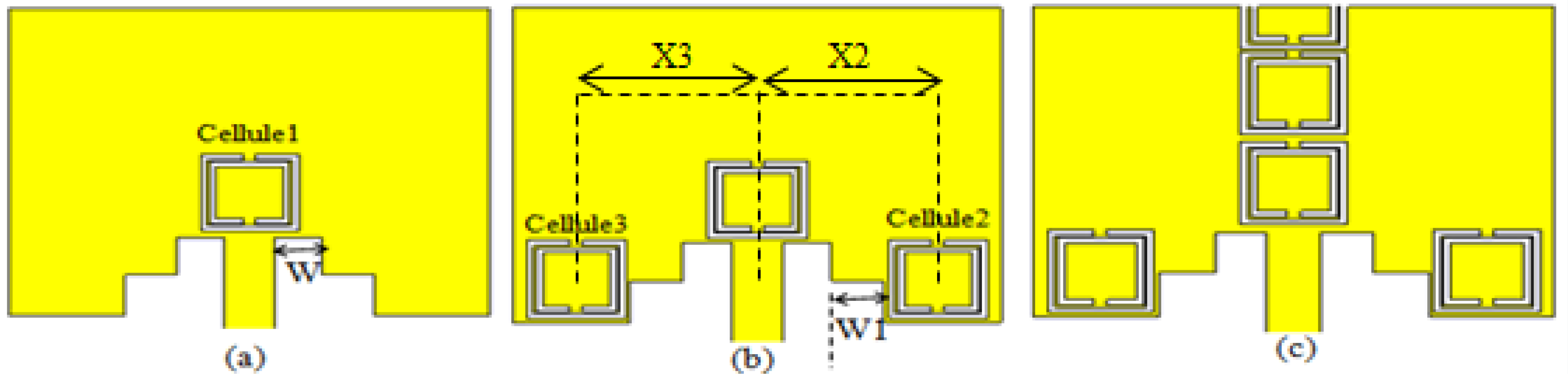
Figure 6 presents three proposals for the radiating element of the initial antenna combined with CSRR cells. We have modified the number of CSRR cells on the radiating element in order to see their influences on the adaptation, while keeping the other antenna parameters unchanged.
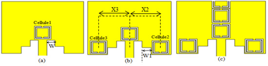
Figure 6.
(a) Radiating element plus a CSRR cell. (b) Radiating element plus three CSRR cells. (c) Radiating element plus several CSRR cells.
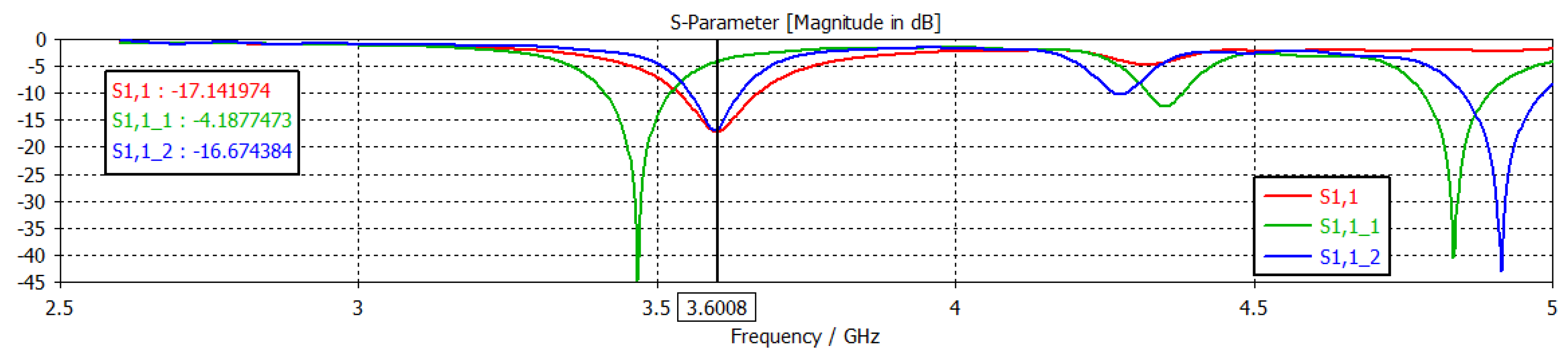
Figure 7 represents, respectively, the return losses for the three structures proposed previously.
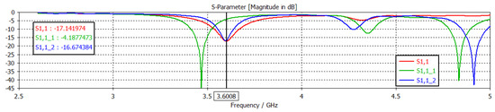
Figure 7.
Return losses for the three structures, respectively.
The notes that can be extracted from these curves are:
The simulation result for the first structure of a CSRR cell (Figure 6a) gives a monofrequency operation with a return loss of −17.14 dB at the resonant frequency 3.6 GHz. For the second three-cell structure (Figure 6b), the antenna exhibits tri-band operation at the resonant frequencies 3.466 GHz, 4.352 GHz, and 4.834 GHz, with return loss levels below −44.73 dB, −12.55 dB, and −40.45 dB, respectively.
The design result for the last structure, where we inserted several CSRR cells on the radiating element (Figure 6c), shows that the reflected power contains three resonant frequencies—3.596 GHz, 4.275 GHz, and 4.91 GHz—with levels equal to −16.86 dB, 10.29 dB, and −43 dB, respectively.
Accordingly, the best structure one can choose to complete our study is the third structure because of its gives multi-band operation where the first peak of the return loss resonates almost at the desired resonance frequency of 3.6 GHz.
To show the effect of the different geometrical parameters of the chosen structure (the widths W and W1 of the notches, the location X2 of the second CSRR cell, the location X3 of the third CSRR cell, and the length Ls of the ground plane and of the substrate) on the antenna characteristics (Figure 5c), we carried out a parametric study to observe the influence of these elements on the antenna-matching.
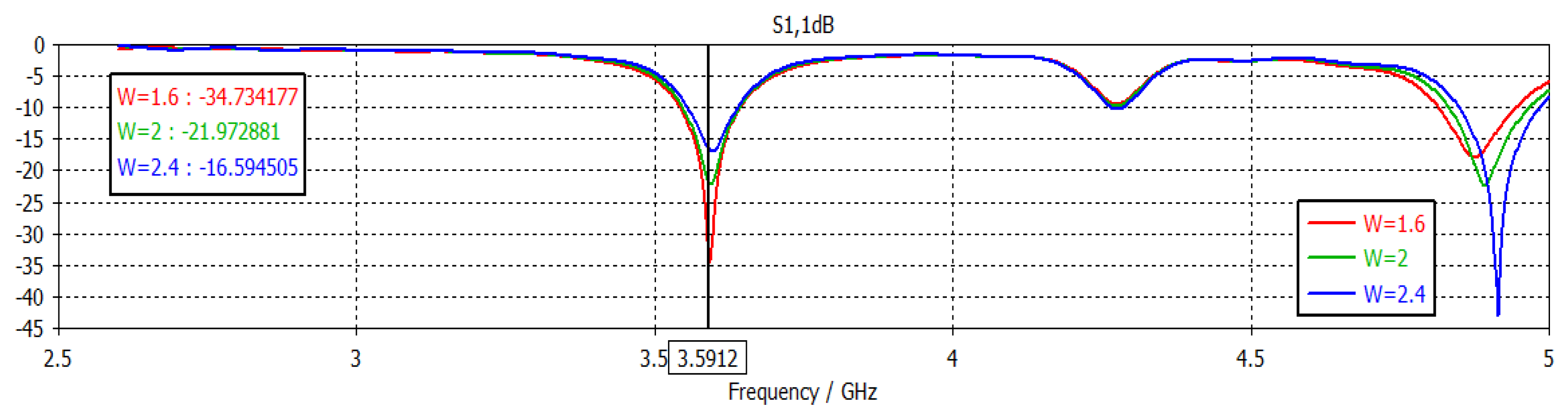
4.1. Variation in Notch Width W
The curves shown in Figure 8 present a dual-band operation in which we observe two resonance frequencies: the first is at 3.59 GHz and the second is around 4.9 GHz.
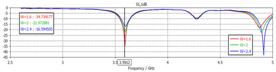
Figure 8.
Influence of the notch width W on adaptation.
We notice that the level of the return loss is inversely proportional to the notch width W for the first peak, where the decrease of the width W leads to an increase of the S11 level. For the second peak, the return loss increases when W increases. The best obtained result corresponds to W = 1.6 mm, such that the return loss reaches a value lower than −34.73 dB at the frequency 3.5912 GHz.
4.2. Variation of the Notch Width W1
The variation of the width W1 of the simulated antenna by CST MWS by fixing the width W to 1.6 mm is shown in Figure 9. This geometry appears as the most promising for W1 = 2.3 mm, where the amplitude of the reflected power is less than −47.66 dB at the desired frequency 3.5864 GHz. This variation provides a particular improvement in the adaptation of the antenna compared to the previous study.
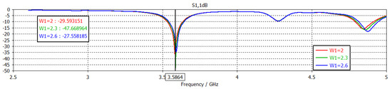
Figure 9.
Influence of the notch width W1 on adaptation.
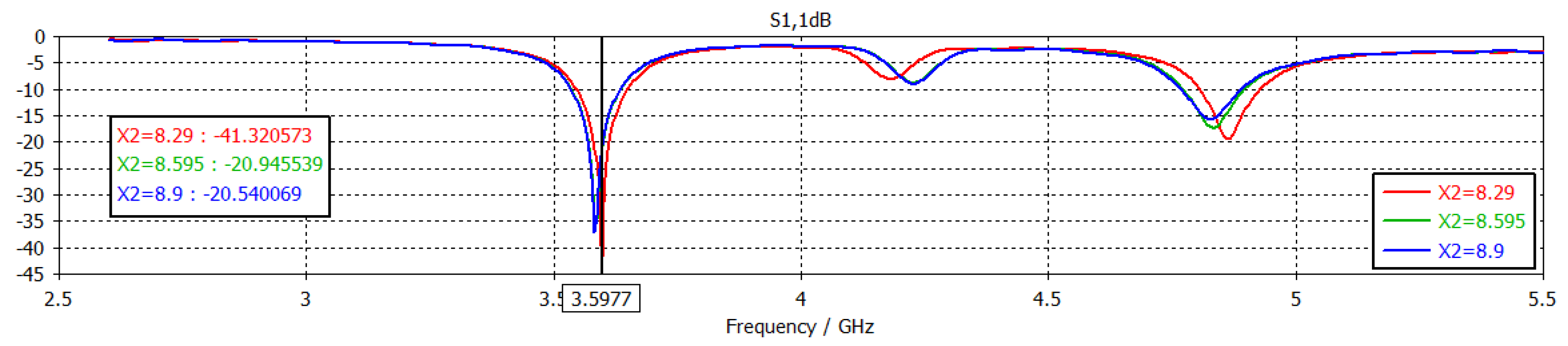
4.3. Variation of the X2 Distance of Second CSRR Cell
From the obtained results, we can visualize that the increase of the return loss level is inversely proportional to the X2 distance. We also observe a slight improvement in the resonance frequency that becomes to equal 3.5977 GHz, almost equal to the desired resonance frequency 3.6 GHz.
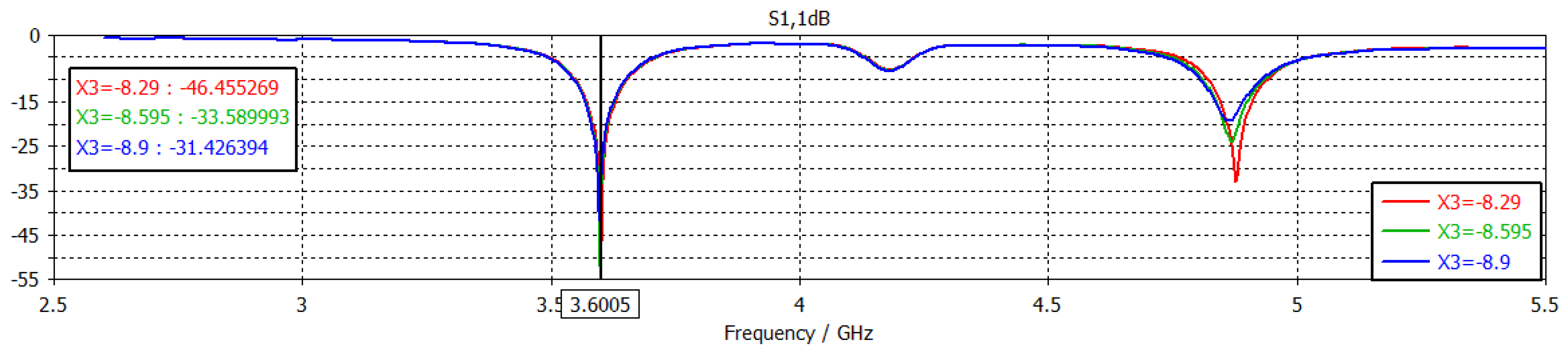
4.4. Variation of the X3 Distance of the Third CSRR Cell
In this phase, we made a slight variation to this distance by placing X2 at 8.29 mm. Figure 10 shows us that the curves are almost identical in the shape, but they have different levels of the return loss S11.
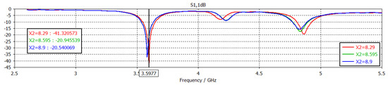
Figure 10.
Influence of the X2 distance on adaptation.
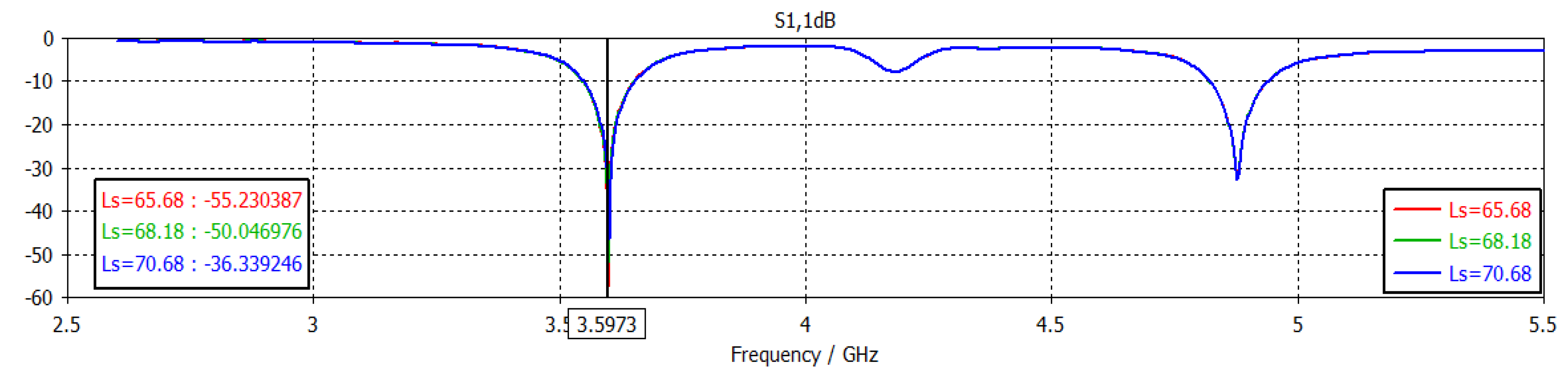
4.5. Variation of the Length Ls of the Ground Plane and the Substrate
Now, we are interested in the influence of the length Ls of the ground plane and the substrate on the adaptation by fixing X3 at 8.29 mm (Figure 11).
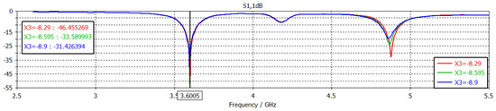
Figure 11.
Influence of the X3 distance on adaptation.
According to Figure 12, the curves have identical shapes with different levels of the return loss. It is noticed that the reflection coefficient is inversely proportional to the length Ls of the ground plane and the substrate. The best result recorded corresponds to the length Ls = 65.68 mm.
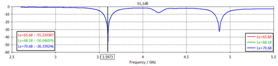
Figure 12.
Influence of the length Ls on adaptation.
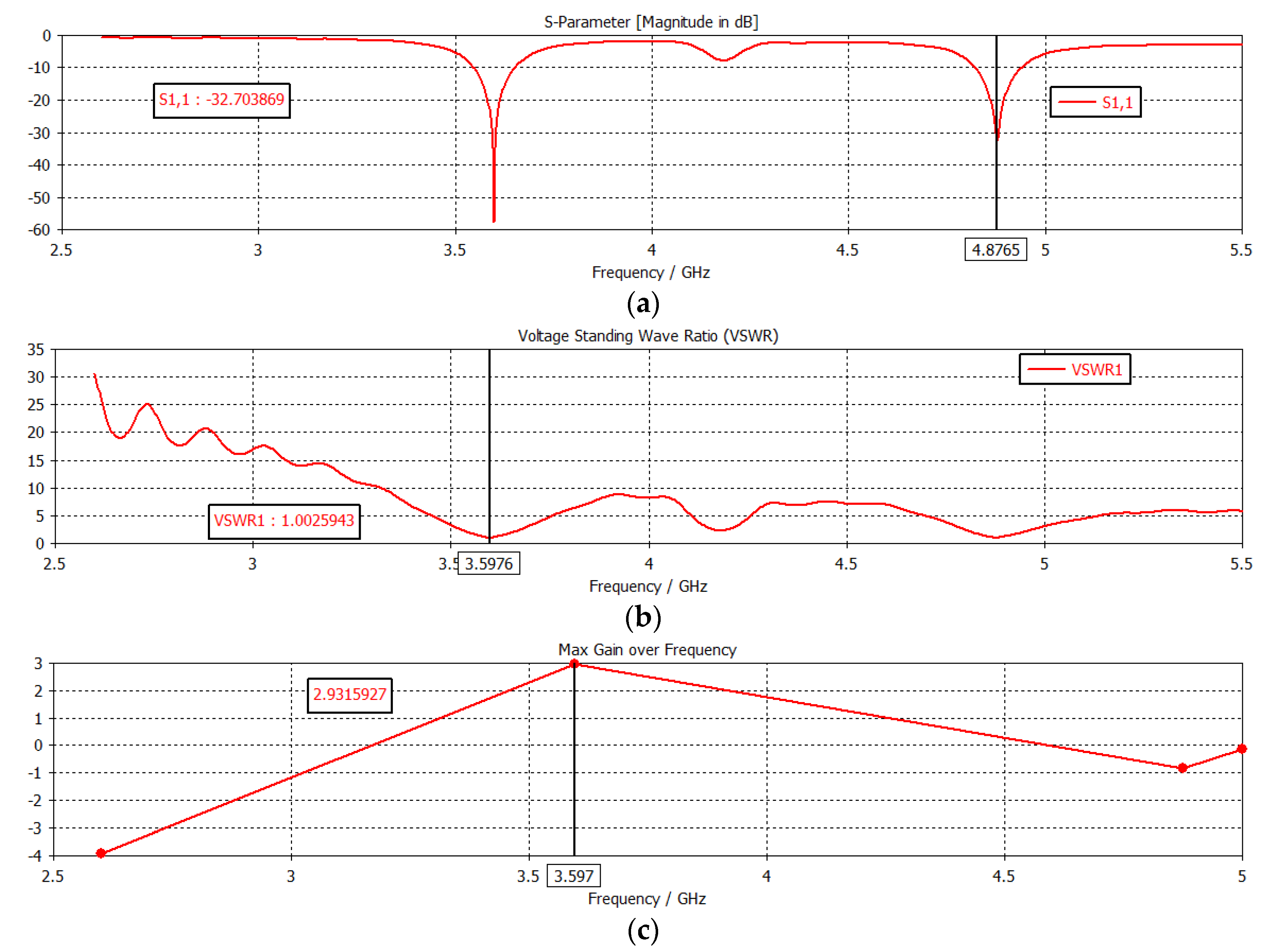
In Figure 13a–c, respectively, we represent the return loss, the VSWR, and the gain of the final dual-band antenna according to the last parametric study of the length Ls.
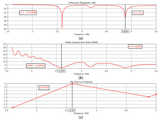
Figure 13.
(a) Return loss. (b) Stationary wave rate. (c) Antenna gain.
According to the last study that we carried out and for Ls equal to 65.68 mm, the simulation results bring back a perfect adaptation to the resonance frequencies for a dual-band antenna. From Figure 13a, it can be said that the reflected power at the antenna input is zero since the two peaks reach values less than −55.23 dB and −32.70 dB at the frequencies 3.597 GHz and 4.876 GHz, respectively, according to the 5G and Wi-Fi systems. This result is very encouraging when comparing it with the initial result we recorded in our main antenna (Figure 1) with a miniaturization rate of around 07.07%.
We have also presented the stationary wave rate, which is of the order of one for each of the two resonance frequencies, which gives a good impedance match between the antenna and the feed line. The bandwidths are of the order of 101.5 MHz and 116 MHz for the two resonance frequencies, respectively. The antenna gain is around 2.93 dB at the 3.597 GHz resonance frequency.
Moreover, we find that the percentage of miniaturization of 07.07% is the best since it presents a perfect adaptation and a very satisfactory frequency band.
5. Conclusions
During this work, we have studied and designed a rectangular patch antenna intended for the new generation of mobile telephony, the fifth generation (5G). To learn about the effect of meta-material technology on printed antennas, we have inserted CSRR cells on the proposed rectangular patch antenna. The new geometry simulated by the CST Microwave Studio software presents a miniature bi-band antenna based on meta-materials according to the two 5G and Wi-Fi systems.
Author Contributions
All authors contributed to this proceeding paper article. All authors have read and agreed to the published version of the manuscript.
Funding
This research received no external funding.
Informed Consent Statement
Informed consent was obtained from all subjects involved in the study.
Data Availability Statement
Data sharing not applicable.
Conflicts of Interest
The authors declare no conflict of interest.
References
- Hajri, S.E. L’amélioration des Performances des Systèmes sans fil 5G Par Groupements Adaptatifs des Utilisateurs. Ph.D. Thesis, Université Paris-Saclay, Paris, France, 2018. [Google Scholar]
- Borhani Kakhki, M. Antennes à Formation de Faisceaux en Ondes Millimétriques Basées sur des Métamatériaux Pour les Applications 5G. Ph.D. Thesis, Université du Québec, Quebec City, QC, USA, 2020. [Google Scholar]
- Kristou, N. Étude et Conception de Métamatériaux Accordables Pour la Miniaturisation D’antennes aux Fréquences Microondes. Ph.D. Thesis, Universite de Rennes 1, Paris, France, 8 June 2018. [Google Scholar]
- Pendry, J.B.; Holden, A.J.; Robbins, D.J.; Stewart, W.J. Extremely Low Frequency Plasmons in Metallic Meso structures. Phys. Rev. Lett. 1996, 25, 4773–4776. [Google Scholar] [CrossRef] [PubMed] [Green Version]
- Krowne, C.M.; Zhang, Y. Physics of Negative Refraction and Negative Index Materials: Optical and Electronic Aspects and Diversified Approaches, 1st ed.; Springer: Berlin/Heidelberg, Germany; New York, NY, USA, 2007. [Google Scholar]
- Nacer, A. Etude et conception de structures à base de métamatériaux pour application aux circuits microondes et antennes. Ph.D. Thesis, University of Tlemcen, Tlemcen, Algeria, 22 December 2018. [Google Scholar]
- Bilotti, F.; Toscano, A.; Vegni, L. Design of Spiral and Multiple Split-Ring Resonators for the Realization of Miniaturized Metamaterial Samples. IEEE Trans. Antennas Propag. 2007, 55, 2258–2267. [Google Scholar] [CrossRef]
- Sahu, B.; Tripathi, P.; Singh, R.; Singh, S.P. Dual segment rectangular dielectric resonator antenna with metamaterial for improvement of bandwidth and gain. Int. J. RF Microw. Comput.-Aided Eng. 2014, 24, 646–655. [Google Scholar] [CrossRef]
- Bait-Suwailam, M.M.; Siddiqui, O.F.; Ramahi, O.M. Mutual Coupling Reduction Between Microstrip Patch Antennas Using Slotted-Complementary Split-Ring Resonators. IEEE Antennas Wirel. Propag. Lett. 2010, 9, 876–878. [Google Scholar] [CrossRef]
- Balanis, C.A. Antenna Theory Analysis and Design; Arizona State University: Tempe, AZ, USA, 2005. [Google Scholar]
- Bahl, I.J.; Bhartia, P. Microstrip Antennas; Artech House: Norwood, MA, USA, 1980. [Google Scholar]
- Balanis, C.A. Advanced Engineering Electromagnetics; John Wiley & Sons: New York, NY, USA, 1989. [Google Scholar]


Publisher’s Note: MDPI stays neutral with regard to jurisdictional claims in published maps and institutional affiliations. |
© 2022 by the authors. Licensee MDPI, Basel, Switzerland. This article is an open access article distributed under the terms and conditions of the Creative Commons Attribution (CC BY) license (https://creativecommons.org/licenses/by/4.0/).