Proceeding Paper

Qualification Process for Additive Manufactured Metallic Connecting Flanges for Space Launcher †
by
Stefania Franchitti
1,*,
Rosario Borrelli
1,
Francesco Di Caprio
2,
Giorgio Buonaiuto
3 and
Antonino Squillace
3
1
Additive Manufacturing LAB, Centro Italiano Ricerche Aerospaziali, 81043 Capua, Italy
2
Crashworthy Structures & Testing LAB, Centro Italiano Ricerche Aerospaziali, 81043 Capua, Italy
3
Department of Chemical Materials and Production Engineering, University of Naples Federico II, 80125 Naples, Italy
*
Author to whom correspondence should be addressed.
Presented at the 15th EASN International Conference, Madrid, Spain, 14–17 October 2025.
Eng. Proc. 2026, 133(1), 77; https://doi.org/10.3390/engproc2026133077
Published: 7 May 2026

Abstract

Additive layer manufacturing is changing the industrial landscape worldwide, particularly in high-end technology sectors, including aerospace applications. In mechanical engineering, and particularly in the aerospace industry, it is essential for quality certification that components are produced using qualified and robust manufacturing processes that guarantee high product repeatability. Unfortunately, nowadays, too few standards are available for the qualification of products manufactured by additive technologies for the aerospace sector. The aim of this work is to qualify a metallic space component, manufactured by additive technology, according to ESA ECSS standards: in particular, the qualification of a non-conventional configuration of the interfacing flanges used to connect two adjacent space launcher’s stages, manufactured by Electron Beam-Powder Bed Fusion (EB-PBF) additive technology, is presented in the present work.

1. Introduction

In response to the growing demand for satellite and spacecraft launches, governments and private companies are seeking to enhance launcher performance and reduce costs. Multistage architectures (Figure 1a) are the most attractive option, as shedding mass during ascent improves overall efficiency. This configuration requires stacking the stages and separating them once they are no longer needed [1]. Traditionally, each stage is produced separately and assembled at the launch site using massive, machined aluminum ring flanges, which generate substantial material waste and involve high assembly time and cost [2].
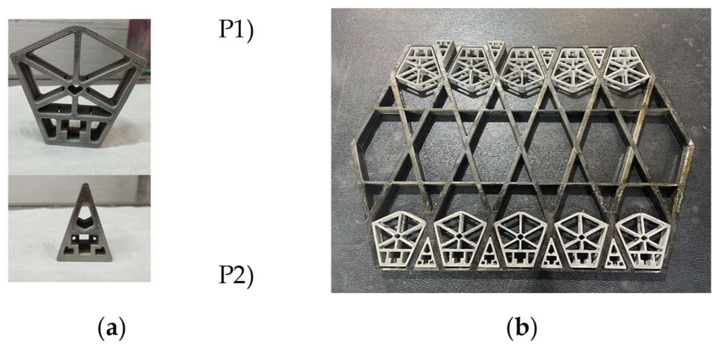
This paper presents the qualifications of an innovative stage-connection system. The new design replaces traditional aluminum flanges with two ALM-manufactured titanium components (Part P1 and Part P2 in Figure 2a) arranged around the circumference and integrated directly into the composite panel. Composite fibers are wound onto these flanges via filament winding, creating a tailored, single-body structure. This solution reduces manufacturing and assembly time and cost, improves structural performance through significant weight savings, and thereby increases launcher capability. The configuration was developed to meet the design requirements of the Vega-C launcher’s 2/3 Interstage (Figure 1b), a monolithic anisogrid composite structure well suited as a case study. Further details on the flange design and the general component are provided in [3,4].
ALM is a layer-wise additive fabrication process that eliminates cutting tools typical of subtractive methods. Its aerospace benefits include reduced lead time and cost, the capability to realize high-complexity, weight-optimized geometries, part consolidation, and consequent improvements in operational and fuel efficiency [5].
The innovative flange system has been designed and manufactured by using the ARCAM A2X platform, based on Electron Beam-Powder Bed Fusion (EB-PBF) technology [6,7], in Ti6Al4V titanium alloy, selected for its high compatibility with composite material (Figure 2b). This work reports the qualification activities of the connection flanges in compliance with ESA ECSS requirements (ECSS-Q-ST-70-80C [8]).

2. Materials and Methods

A qualification procedure was defined in accordance with ECSS-Q-ST-80C, which specifies processing and quality-assurance requirements for metallic PBF-ALM parts used in space applications. This standard—previously applied by the authors for qualifying metallic supports of the Space Rider system [9]—comprises three phases:
  • Definition phase: Hardware requirements are assessed against ALM process constraints to determine feasibility. Critical parameters (material, chemistry, powder size, supplier, etc.) and manufacturing equipment are selected, and process/equipment limitations are compared with project specifications.
  • Verification phase: This includes process verification and prototype verification. Process verification establishes admissible material properties through targeted testing (powder characterization, tensile and fatigue tests, etc.), generating a transferable material database. Prototype verification validates the ALM end-to-end process at part level by testing powders, witness samples, and prototypes to confirm compliance with defined properties. For new projects, process verification may be skipped if a suitable material database already exists, but prototype verification is always mandatory.
  • Hardware production: Parts are produced according to the verified procedure.
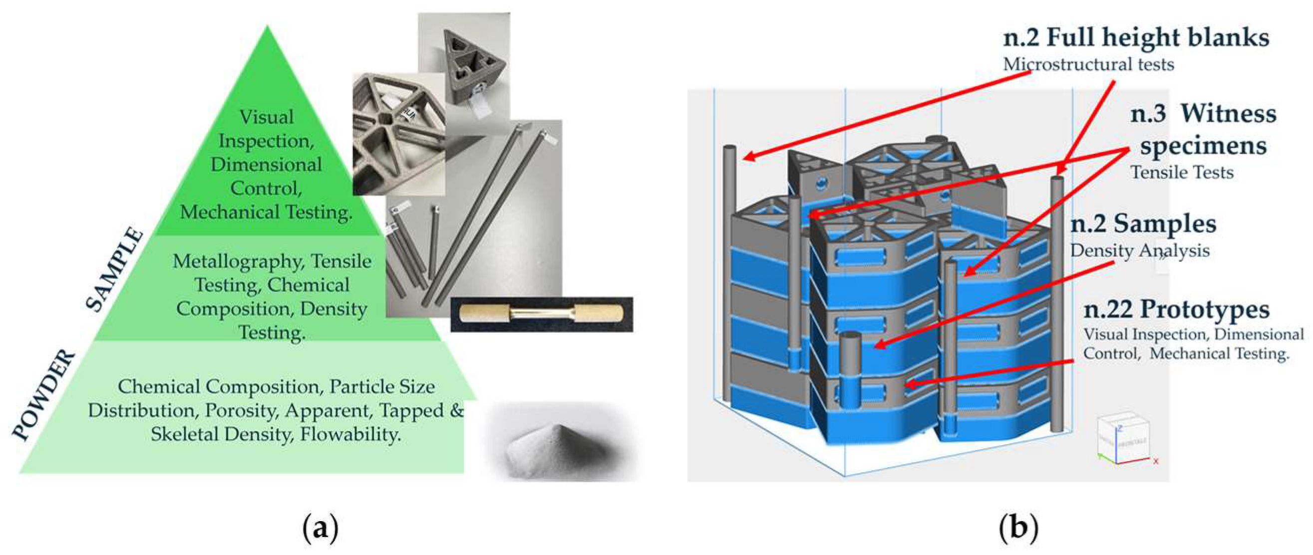
This paper focuses on prototype verification using the building block approach (Figure 3a), starting with powder-level tests, then specimen-level, and finally prototype-level. As shown in Figure 3b, 22 flange prototypes were produced in a single 61 h job, along with witness samples and full-height blanks for validation purposes. Specifically:
  • Three witness samples: tensile tested per ASTM E8/E8M-2024 [10] with extensometers to collect strain data up to 3% strain.
  • Two samples: used for density analysis.
  • Two full-height blanks: used for microstructural and defect analysis. A full-height blank was selected, and the first 20 mm from the build plate were removed to exclude the initial machine transient. The remaining portion was sectioned into three regions—bottom, middle, and top. From each region, one cross-sectional and one longitudinal sample were prepared, resulting in six samples in total. All samples were embedded in resin and polished to a mirror finish for microstructural examination.
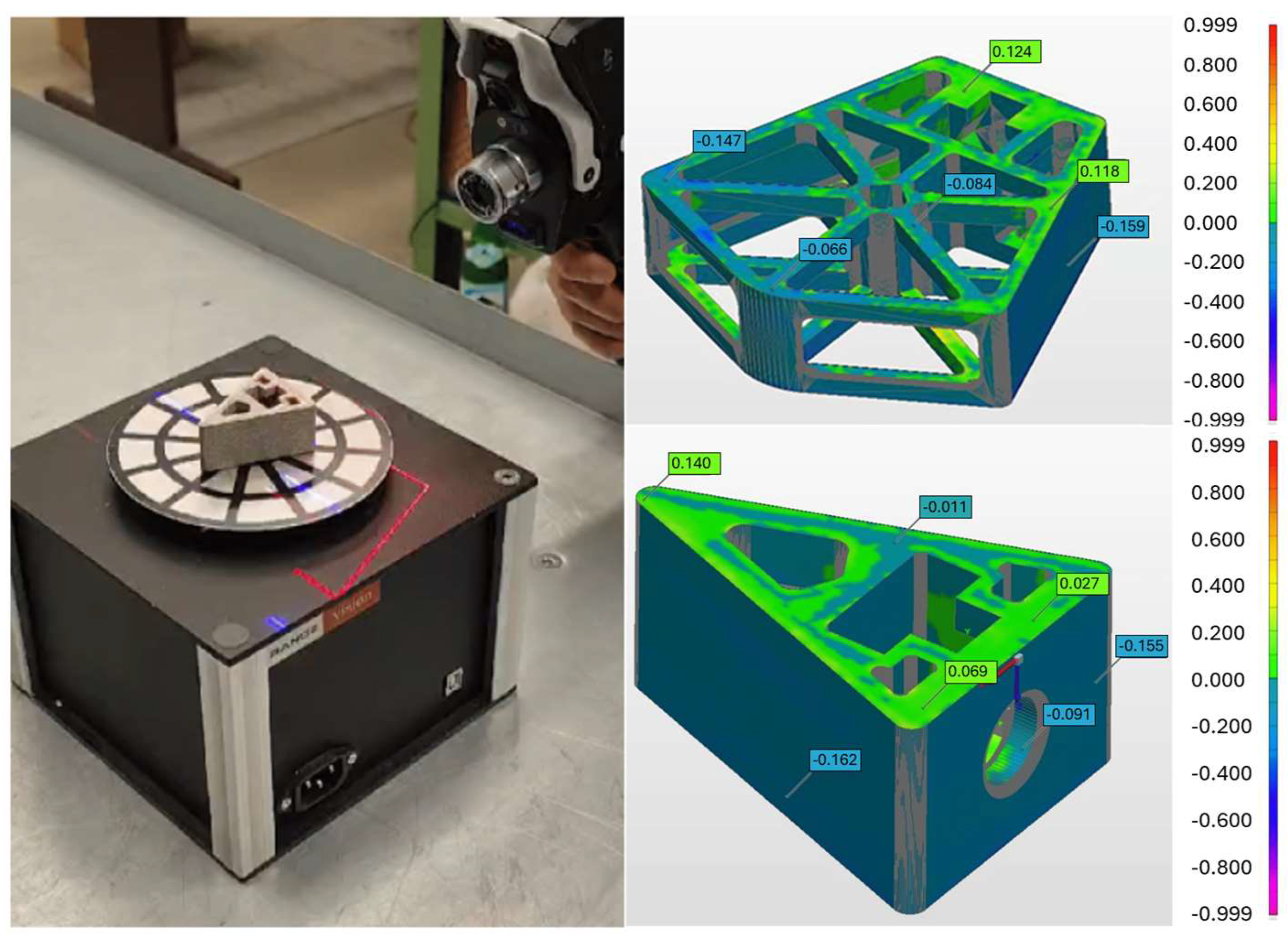
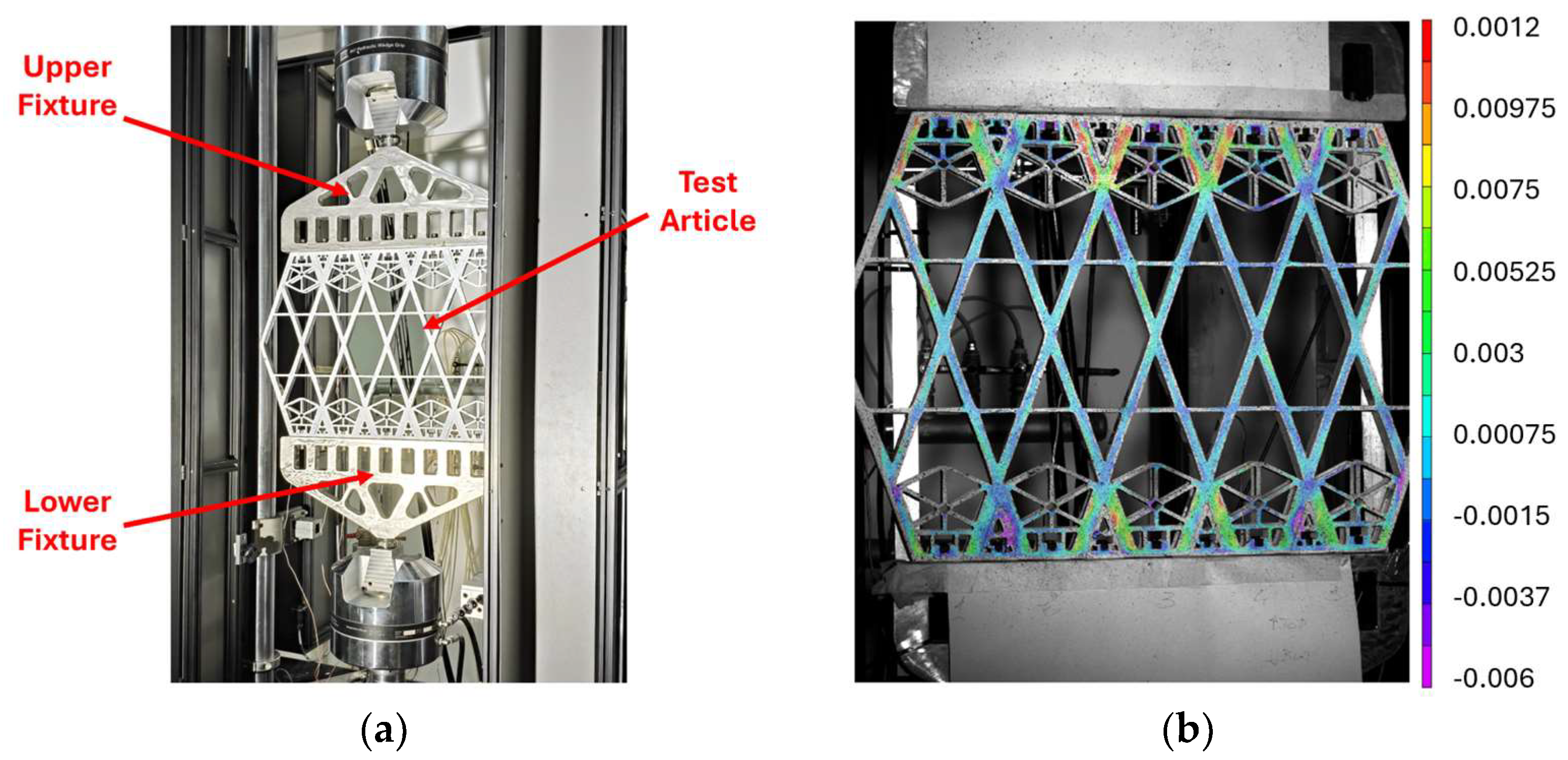
Powder samples were also characterized for compliance via tests on chemical composition (ASTM E2371, E1447, E1409, E1941), particle size (ASTM B214), apparent, tapped, and skeletal density (ASTM B212, B527, B923), and flow rate (ASTM B213). Particle size was measured by sieving 90–110 g of powder through 150–25 μm meshes for 15 min. Apparent density was calculated using a calibrated beaker, tapped density was determined by measuring the apparent density of 100 g of powder after it was compacted by tapping (3000 taps), skeletal density via helium pycnometer, and flowability by timing 50 g of powder through a calibrated funnel. After validating powders and witness samples, dimensional checks and static mechanical tests were performed on the flanges. A Hexagon RS6 Laser Scanner on a 7-axis arm compared scans to CAD models. Finally, flanges were integrated into a flat, anisogrid panel and subjected to a uniaxial tensile test (600 kN/m)—reproducing the in-service load conditions expected for the components—using custom grips, with full-field deformation measured by DIC.

3. Results

3.1. Definition Phase

EB-PBF technology (ARCAM A2X model), available at CIRA, was chosen as the manufacturing process. Among the materials that can be processed in ARCAM A2X, the Ti6Al4V titanium alloy was found suitable to comply with the structural requirements of the parts. Considering the dimensions of prototypes to be produced and available build envelope, in this phase it was chosen to manufacture 22 flanges (12 in P1 configuration and 10 in P2 configuration) in the same job.

3.2. Verification Phase

3.2.1. Process Verification

The material properties database for Ti6Al4V processed with the ARCAM A2X EB-PBF system was already established in a previous project [8]. Hence, according to ECSS-Q-ST-80C, the process verification phase was omitted, and only the prototype verification phase was performed.

3.2.2. Prototype Verification

In this section, the results of the prototype verification phase are presented at the powder, sample, and prototype levels.
Powder Level: The results of the chemical composition analysis carried out on each powder batch are shown in Table 1. All the chemical elements comply with the chemical composition limits required for Ti6Al4V by ASTM F2924-14 [11].
Table 2 presents the PSD analysis results, demonstrating that the powder granulometry is suitable for processing via EB-PBF technology. Also, the results of powder flowability and density, reported in Table 3, indicate that the powder satisfies the processability requirements of the EB-PBF technology.
Sample Level: The results of the tensile tests carried out on three specimens, manufactured at the same time as the prototypes, are shown in Table 4. The results obtained were compared with those of wrought Ti6Al4V [12] and with Ti6Al4V EB-PBF allowables [7]: the resistance to fracture, yield stress, and elongation at fracture were observed to exceed the material’s allowable limits, whereas the modulus of elasticity remained within the specified allowable range.
The chemical analysis results were found consistent with those on the powders. The density test results revealing an average density of 4.428 g/cm3 which is very close to the reference value for Ti6Al4V wrought titanium alloy (4.43 g/cm3), confirming good densification of the material and the absence of significant defects.
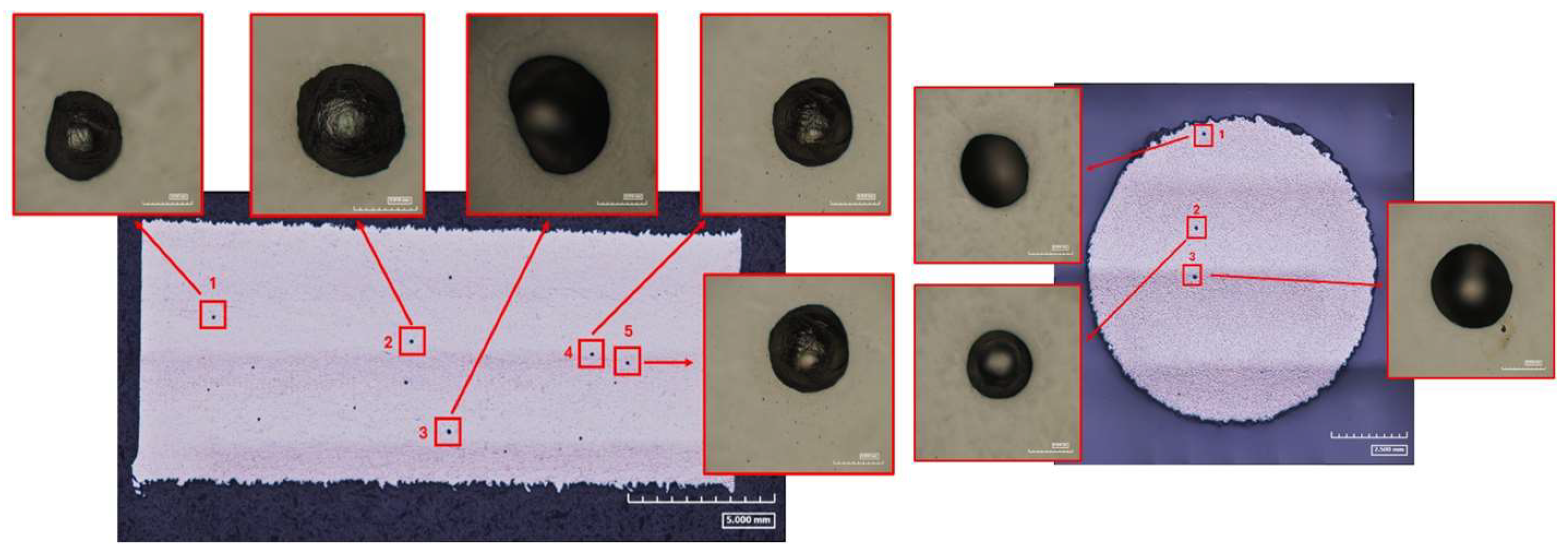
The defect analyses were carried out on the specimens obtained from the full-height blanks: for each section, magnifications of 1000× were used, and five porosities were selected on the longitudinal section and three on the cross section (Figure 4), obtaining the measurements summarized in Table 5.
All measured porosities show dimensions smaller than 200 μm, which are the typical EB-PBF process defects, as confirmed by several bibliographic studies [13,14].
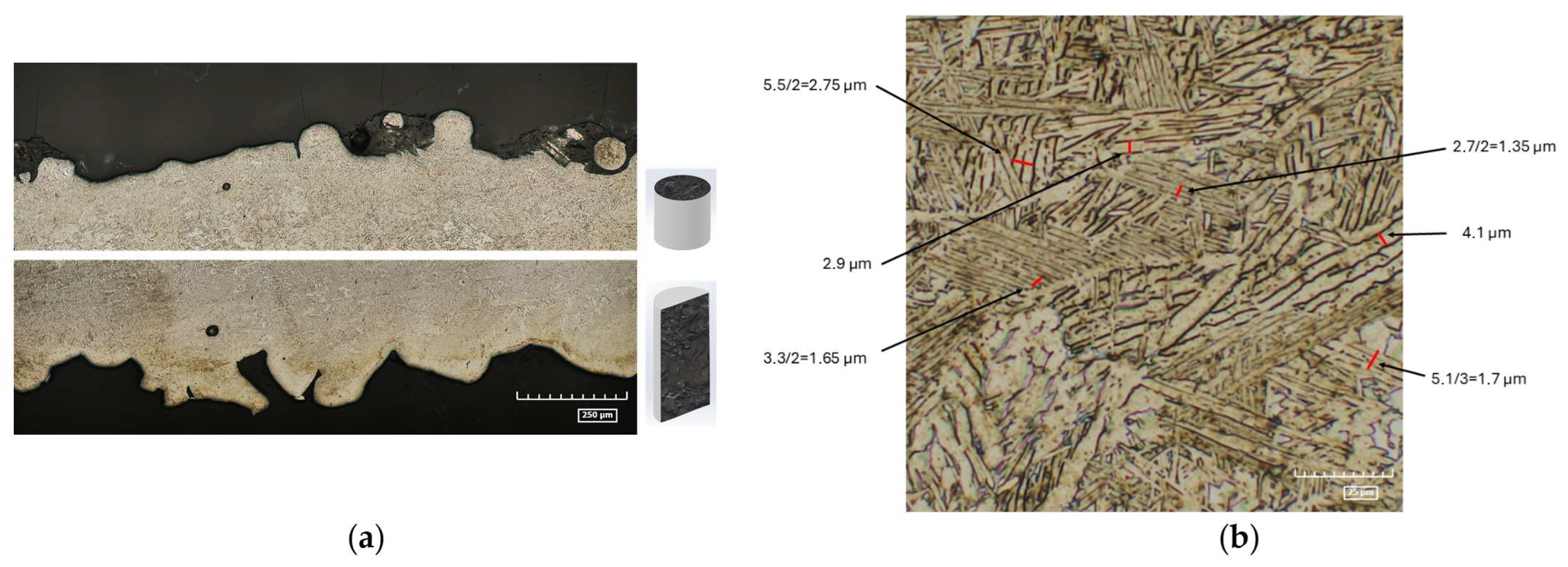
As shown in Figure 5, at magnifications of 500×, it was possible to note the absence on the surface of the samples of alpha case, a very fragile surface layer that forms on titanium products when the material comes into contact at high temperatures with elements that stabilize the alpha phase of titanium, such as oxygen, carbon, nitrogen, etc. The presence of this layer compromises the fatigue and wear resistance of the components, which is why it is important to verify its absence [15].
Using 1500× magnification, it was finally possible to analyze the grain morphology, revealing a lamellar structure with random orientation and variable dimensions, which is typical of EB-PBF-processed titanium due to the different cooling rates in the piece, which are a characteristic of EB-PBF processes.
Prototype Level: During the visual inspection, no anomalies were detected.
The comparison between the CAD model and scan acquisition (Figure 6) shows a dimensional deviation within a range of ±0.2 mm. The deviations observed are in line with the typical characteristics of products manufactured using the EB-PBF technology.
The mechanical test (Figure 7) was executed without any remarkable anomaly: the data acquired are mostly consistent and repeatable, no structural failures in the metallic parts occurred during the test, and finally, the post-test inspection highlighted that the metallic flanges have no visible crack or damage.

4. Conclusions

In this work, the qualification of the additive-manufactured interconnecting metallic flanges to connect two adjacent space launchers’ stages have been described. The EB-PBF process was chosen as ALM technology to produce the components in Ti6Al4V titanium alloy. The prototype verification phase was performed according to a building block approach suggested by ESA standards, starting at the powder level, moving to a specimen level and concluding at the prototype level. The mechanical test at the prototype level proved the capability of the innovative connecting system in sustaining the in-service load. The qualification procedure successfully demonstrated that the EB-PBF technology was an appropriate choice for this type of space application allowing it to reduce manufacturing costs and ensuring a high structural strength of the manufactured components.

Author Contributions

Conceptualization, S.F., R.B., F.D.C. and A.S.; methodology, S.F. and R.B.; validation, S.F., R.B., F.D.C. and A.S.; investigation, G.B.; data curation, S.F. and R.B.; writing—original draft preparation, S.F., R.B. and G.B.; writing—review and editing, all the authors; supervision, S.F. and A.S. All authors have read and agreed to the published version of the manuscript.

Funding

This research received no external funding.

Institutional Review Board Statement

Not applicable.

Informed Consent Statement

Not applicable.

Data Availability Statement

The data presented in this study are available on request from the corresponding author due to privacy restrictions.

Conflicts of Interest

The authors declare no conflicts of interest.

Abbreviations

The following abbreviations are used in this manuscript:
ALMAdditive Layer Manufacturing
CADComputer-Aided Design
DICDigital Image Correlation
EB-PBFElectron Beam-Powder Bed Fusion
PSDParticle Size Distribution

References

  1. Orgeira-Crespo, P.; Rey, G.; Ulloa, C.; Garcia-Luis, U.; Rouco, P.; Aguado-Agelet, F. Optimization of the Conceptual Design of a Multistage Rocket Launcher. Aerospace 2022, 9, 286. [Google Scholar] [CrossRef]
  2. Guo, Y.; Wei, Y.; Yang, Z.; Huang, C.; Wu, X.; Yin, Q. Nonlinearity of interfaces and force transmission of bolted flange joints under impact loading. Int. J. Impact Eng. 2017, 109, 214–223. [Google Scholar] [CrossRef]
  3. Cristillo, D.; Di Caprio, F.; Totaro, G. New conceptual design of connecting metallic flanges for space composite grid structures. In Proceedings of the AIAA AVIATION 2023 Forum, San Diego, CA, USA, 12–16 June 2023. [Google Scholar]
  4. Cristillo, D.; Di Caprio, F.; Petrone, G.; Zallo, A. Design and numerical-experimental validation of supports’ equipment for VEGA-C launcher. In Proceedings of the AIAA AVIATION 2023 Forum, San Diego, CA, USA, 12–16 June 2023. [Google Scholar]
  5. Blakey-Milner, B.; Gradl, P.; Snedden, G.; Brooks, M.; Pitot, J.; Lopez, E.; Leary, M.; Berto, F.; du Plessis, A. Metal additive manufacturing in aerospace: A review. Mater. Des. 2021, 209, 110008. [Google Scholar] [CrossRef]
  6. Fu, Z.; Körner, C. Actual state-of-the-art of electron beam powder bed fusion. Eur. J. Mater. 2022, 2, 54–116. [Google Scholar] [CrossRef]
  7. Franchitti, S.; Pirozzi, C.; Borrelli, R. Influence of hot isostatic pressing and surface finish on the mechanical behaviour of Ti6Al4V processed by electron beam melting. Fatigue Fract. Eng. Mater. Struct. 2020, 43, 2828–2841. [Google Scholar] [CrossRef]
  8. ECSS-Q-ST-70-80C; Space Product Assurance: Processing and Quality Assurance Requirements for Metallic Powder Bed Fusion Technologies for Space Applications. European Cooperation for Space Standardization: Noordwijk, The Netherlands, 2021.
  9. Franchitti, S.; Borrelli, R.; De Fenza, A.; Fauci, R.; De Stefano Fumo, M.; Gardi, R.; Rufolo, G. Qualification process of additive manufactured attachment Supports for the Space Rider Body Flap Assembly. Procedia Struct. Integr. 2024, 53, 397–406. [Google Scholar] [CrossRef]
  10. ASTM E8/E8M-2024; Standard Test Methods for Tension Testing of Metallic Material. American Society for Testing and Materials: West Conshohocken, PA, USA, 2024.
  11. ASTM F2924-14; Standard Specification for Additive Manufacturing Titanium-6 Aluminum-4 Vanadium with Powder Bed Fusion. American Society for Testing and Materials: West Conshohocken, PA, USA, 2021.
  12. ASTM B381-21; Standard Specification for Titanium and Titanium Alloy Forgings. American Society for Testing and Materials: West Conshohocken, PA, USA, 2021.
  13. Gui, Y.; Aoyagi, K.; Chiba, A. Development of macro-defect-free PBF-EB-processed Ti–6Al–4V alloys with superior plasticity using PREP-synthesized powder and machine learning-assisted process optimization. Mater. Sci. Eng. 2023, 864, 144595. [Google Scholar] [CrossRef]
  14. Sandell, V.; Hansson, T.; Roychowdhury, S.; Månsson, T.; Delin, M.; Åkerfeldt, P.; Antti, M.L. Defects in Electron Beam Melted Ti-6Al-4V: Fatigue Life Prediction Using Experimental Data and Extreme Value Statistics. Materials 2021, 14, 640. [Google Scholar] [CrossRef] [PubMed]
  15. Uwanyuze, R.S.; Kanyo, J.E.; Myrik, S.F.; Shaffoner, S. A Review on Alpha Case Formation and Modeling of Mass Transfer During Investment Casting of Titanium Alloys. J. Alloys Compd. 2021, 865, 158558. [Google Scholar] [CrossRef]
Figure 1. (a) Multistage architecture of VEGA C launcher; (b) Interstage 2/3 of the Vega C launcher with traditional separation flange.
Engproc 133 00077 g001
Figure 2. (a) Optimized Part P1 and Part P2 manufactured in Ti6Al4V by ALM technology; (b) Flanges integrated in anisogrid structure.
Engproc 133 00077 g002
Figure 3. Prototype verification phase: (a) Building block approach; (b) Print job design.
Engproc 133 00077 g003
Figure 4. Analysis defects.
Engproc 133 00077 g004
Figure 5. (a) Alpha case assessment; (b) Microstructure of Ti6Al4V AM flanges.
Engproc 133 00077 g005
Figure 6. Dimensional control of prototypes.
Engproc 133 00077 g006
Figure 7. Mechanical Test on flanges integrated into an anisogrid flat panel: (a) Experimental setup; (b) Full-field deformation measured by DIC.
Engproc 133 00077 g007
Table 1. Chemical composition results on powder.
Elements%Measured%Req. (ASTM F2924-14)
C0.01<0.08
Fe0.21<0.30
N0.01<0.05
O0.20<0.20
H0.003<0.015
Al6.605.5 ÷ 6.75
V4.103.5 ÷ 4.50
Tibalancebalance
Table 2. Particle size distribution results.
Particle Size (μm)Measured (% by Mass)Requirement (% by Mass)
<250.06%<0.70%
<452.33%<5.0%
45 ÷ 10694.93%>90%
>1062.33%<5.0%
>1500%<0.20%
Table 3. Flowability and density results.
Capture SampleFlow Rate (s/50 g)Apparent Density (g/cm3)Tapped Density (g/cm3)Skeletal Density (g/cm3)
1222.512.84.417
2212.542.84.410
3212.512.84.409
Average212.532.84.412
Req.<29>2.40>2.74.43
Table 4. Tensile test results.
ID
Sample
Young’s Modulus
[GPa]
Yield Strength
[MPa]
Ultimate Strength
[MPa]
Elongation After Fracture
(L0 = 24.0 mm)
1112.34100210519.2
2117.78983104810.4
3119.401008106710.8
Average116.51998105510.1
CV3.17%1.32%0.94%0.87
Std. Dev.3.7013.139.948.55%
Wrought110–12082889510.0
EB-PBF Allowables115.3095810207.0 1
1 As prescribed by ECSS-Q-ST-80C.
Table 5. Defects dimensions.
SECTIONPorosities [μm]
BOTTOM12345
Longitudinal
Cross
741081048493
848241--
MEDIUM12345
Longitudinal
Cross
78911049189
857495--
TOP12345
Longitudinal
Cross
86891148686
486956--
Disclaimer/Publisher’s Note: The statements, opinions and data contained in all publications are solely those of the individual author(s) and contributor(s) and not of MDPI and/or the editor(s). MDPI and/or the editor(s) disclaim responsibility for any injury to people or property resulting from any ideas, methods, instructions or products referred to in the content.