1. Introduction
One of the major challenges facing modern aviation is improving fuel efficiency. Reducing fuel consumption and its associated climate impact depends on a range of technological advances across multiple disciplines. At aircraft level, three core domains act as pivotal levers for energy savings: Lightweight structures, propulsion system, and aerodynamic performance. A key challenge in the field of aerodynamics is the significant impact of viscous drag, which, according to Schrauf [
1], accounts for over half of an aircraft’s total drag. This observation underlines a compelling opportunity, namely that laminar-flow technologies can markedly reduce skin friction drag, thereby lowering total aircraft drag. Another important aspect of realising the full potential of laminar flow is adapting the wing planform simultaneously.
The use of laminar flow aerodynamics dates back to the 1930s, when NACA 6- and 7-series airfoils were first developed [
2] and continued in the 1990s with a series of wind-tunnel experiments and flight tests that produced the first guidelines for natural laminar flow (NLF), identifying the Reynolds number and wing-sweep regimes in which laminar flow could be sustained [
3]. Subsequent flight test campaigns have validated hybrid laminar flow control (HLFC) on various aircraft, including the JetStar wing [
4], a Boeing 757 [
5], and the A320 fin [
6].
The use of laminar flow aerodynamics was investigated in the Clean Sky 2 HLFC-Win project, which focused on the integration of a Hybrid Laminar Flow Control (HLFC) system into the outer leading edge of a long-haul aircraft using a full-scale demonstrator [
7]. The study confirmed that an HLFC system could be incorporated into a wing’s leading edge in an industrial context. Performance and economic assessments indicated a block fuel reduction of over 3% for the design mission compared with a comparable turbulent-wing aircraft, translating to an estimated 1% decrease in life-cycle cost under favourable economic scenarios [
8]. Fröhler et al. [
8] emphasised that even greater drag reductions could be achieved by considering laminar-flow technologies from the earliest stages of aircraft design. This would require adjustments to the wing planform and a redesign of the airfoil, as well as multidisciplinary optimisation of aerodynamics, structure and systems.
To address this issue, the German Aerospace Center (DLR) project LamTA was initiated to design a long-range aircraft tailored for laminar flow. A conceptual design methodology was employed to systematically evaluate the benefits of laminar flow across all major aircraft components, including the wing, empennage, nacelle, and fuselage. However, assessing aerodynamic improvements in isolation, without considering the overall mass, system power requirements or engine performance, provides an incomplete view of the technology’s true potential. Consequently, the assessment of laminar-flow technologies must consider the mass and power penalties of HLFC systems alongside their aerodynamic advantages. To this end, a system sizing methodology based on [
9] has been integrated directly into the aircraft design workflow. The ultimate goal of this work is to address the following research question:
How do laminar-flow technologies affect aerodynamic performance and the resulting improvement in fuel efficiency, taking into account structural masses, engine and system design, and their interactions when systematically considered in conceptual aircraft design?
2. Conceptual Aircraft-Design Approach
An Aircraft-Design Environment (ADE) is indispensable for obtaining a consistent, comprehensive representation of an aircraft. It encompasses geometry, aerodynamics, mass properties, engine specifications, system design, and overall performance.
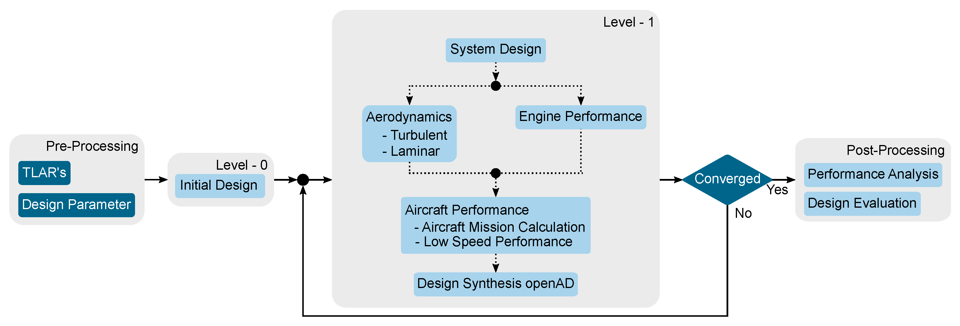
Figure 1 shows the ADE workflow. It starts with the definition of the top-level aircraft requirements (TLARs) and design-specific data, then initiates a Level L0 analysis using the DLR conceptual design tool openAD [
10]. Subsequent higher-fidelity disciplinary tools (system design, aerodynamic, engine, and performance models) run on Level L1; their results are fed back into openAD for synthesis.
The design approach proceeds as follows. First, a reference aircraft, a representative of current state-of-the-art design, is defined and calibrated against the conceptual design methods. This aircraft is then projected to 2035, the anticipated maturity year for laminar-flow technologies, thereby establishing a baseline that incorporates evolutionary improvements. Finally, the higher-fidelity disciplinary methods and the specific integration of laminar-flow technologies are described in detail.
2.1. Reference and Baseline Aircraft Design
A reference aircraft has been selected that is expected to be suitable for the integration of laminar-flow technologies. The DLR internal project oLAF [
11] has designed a long-range aircraft for which detailed information is already available. The TLARs, as listed in
Table 1, form the basis for the oLAF aircraft and the subsequent design for the reference and baseline. For the existing reference configuration, the year 2025 was assumed to be the state of the art, as a geared turbofan engine and an optimised wing were already included. The reference aircraft is based on technologies that represent the current state of the art, while the revolutionary technologies are assumed to enter service in the future, resulting in an unfair comparison. This is avoided by projecting the reference aircraft forward using evolutionary technologies to establish comparability. This so-called baseline aircraft is projected to 2035, with technology assumptions for mass, aerodynamics, and engine performance corresponding to the technology scenario. Various technology assumptions were made for the baseline aircraft in order to create a sound basis for the technology assessment. For the propulsion system, a 4–5% reduction in mass was obtained by adopting the “Rubber Engine” assumptions for a bypass-ratio of 12, as described by Häßy et al. [
12]. The structural mass of the wing and fuselage each decreased by 5% relative to the conventional baseline, due to advanced manufacturing techniques, updated requirements, and refined specification sets. The empennage mass was found to have reduced by 3%, reflecting similar improvements in its design specifications. In addition, the aircraft was designed with no laminar flow, no further mass reduction through load alleviation (it is included in the −5% wing structure mass), and a cruise Mach number of 0.83, which remained the reference.
2.2. System Design
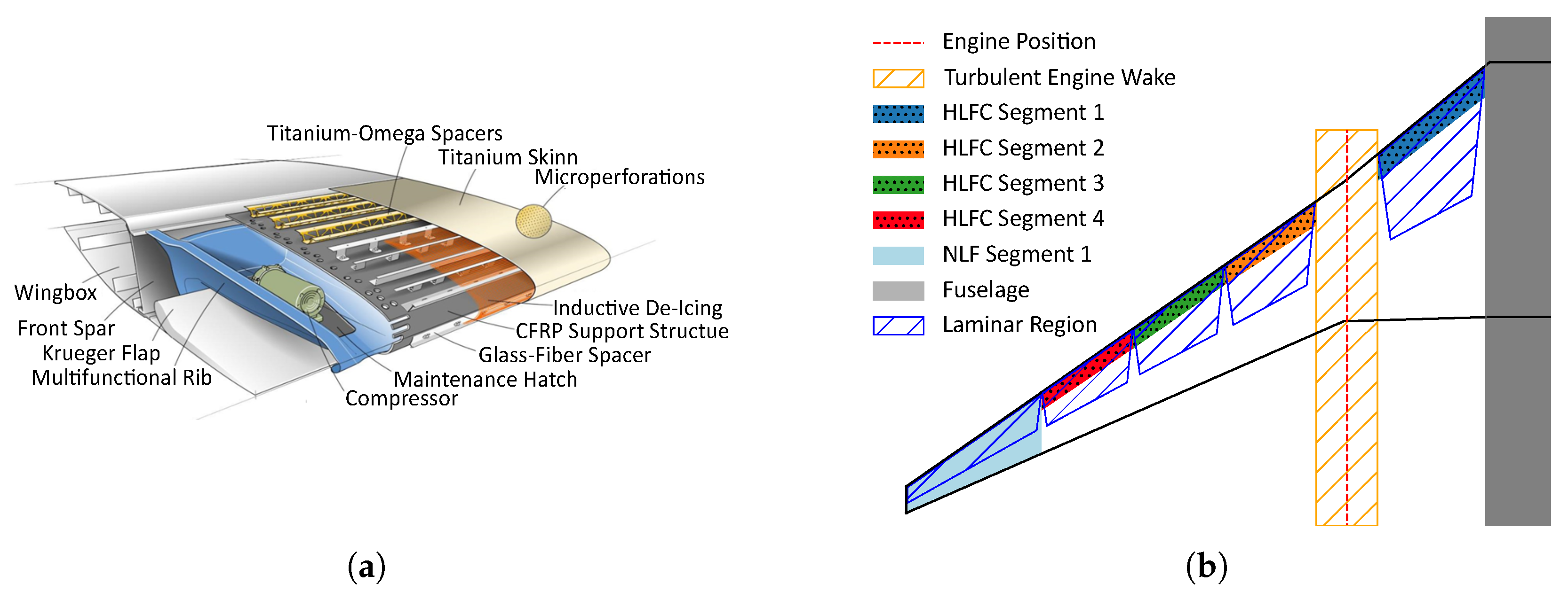
For integrating active laminar flow systems, such as HLFC, the system design, with its many design choices, is inherently complex (see
Figure 2a). Many different design choices need to be considered, including system complexity, mass, power requirements, and operational costs. Therefore, the approach developed by Risse [
9] was adopted and integrated into the ADE. The integrated tool allows for data exchange with the Common Parametric Aircraft Configuration Schema (CPACS), a subsystem design for wing, empennage, nacelles, and fuselage, and for the estimation of power requirements and the mass of each subsystem and its components. The system design requires a dataset of available reference data, which was provided by the previous European CleanSky 2 project HLFC-Win [
7,
8].
With many design choices available, several assumptions based on previous experiences are included in the design. The wing, as a major component of the aircraft, is the first to be equipped with laminar technologies. The general arrangement (see
Figure 2b) is to integrate HLFC for the inner wing with one segment (segment 1) and the outer wing with three segments (segments 2 to 4). A laminar to turbulent transition location at 60% chord is assumed for the entire laminar area. Near the wing tip, natural laminar flow (NLF) is feasible, which requires no system integration and no mass penalty is assumed. For the HLFC system, two compressors per suction panel are integrated. Turbulent wedges are formed at the interface between each suction panel, reducing the laminar area with a 7.5° contraction on each side. In addition, the laminar area is reduced by the engine wake.
Similar to the wing, the empennage is also equipped with HLFC. Both the horizontal and vertical tail plane (HTP and VTP) have a single suction panel with two compressors to provide the suction pressure. The same assumption is made for the turbulent wedges with a 7.5° contraction on each side and a 60% transition point. The nacelle incorporates several assumptions when introducing laminar flow. For the estimated 30% transition area around the full circumference, it is assumed that there is no interaction with the pylon attachment or maintenance holes to be considered. Ground contamination is also assumed to be negligible. The fuselage in particular has large uncertainties in estimating the transition location and, in general, the total laminar area on the fuselage surface. The uncertainties are due to the lack of knowledge of laminar flow at the complex cockpit geometry, the placement of attachments to the fuselage (e.g., instrumentation or rain gutters at the doors), or the avoidance of surface irregularities from windows or doors. For the initial design, it is assumed that a transition location at 40% is possible. However, there is no laminar flow under the aircraft due to contamination (such as dirt, dust, ice, or snow) and other irregularities, such as landing gear openings. It is also assumed that doors, windows, and systems can be integrated without disturbing the laminar flow.
2.3. Aerodynamic Considerations
Aerodynamic modelling is crucial for an accurate estimation of the laminarity effect on overall aircraft performance. Two in-house DLR tools, LiLi (Lifting-Line) and HandbookAero (HB), are employed to evaluate the full flight envelope [
14]. LiLi is a multi-lifting-line code that computes lift, induced drag, and pitching moment for non-planar wings. It relies on inviscid, irrotational potential flow theory with a thin-airfoil assumption and includes a subsonic compressibility correction. HB supplies the viscous drag components that LiLi omits, which are built on established semi-empirical handbook methods. Both tools are CPACS-compatible and operate directly on the geometry defined in the data set. Wave drag and pressure drag are evaluated in a separate Python 3.12 script following an approach by Torenbeek [
15].
Based on the previously discussed approach, the reference aircraft and, consequently, the baseline aircraft are calibrated to known aerodynamic coefficients. This provides the basis for integrating laminar flow into the different components and tailoring the wing planform to the aircraft design.
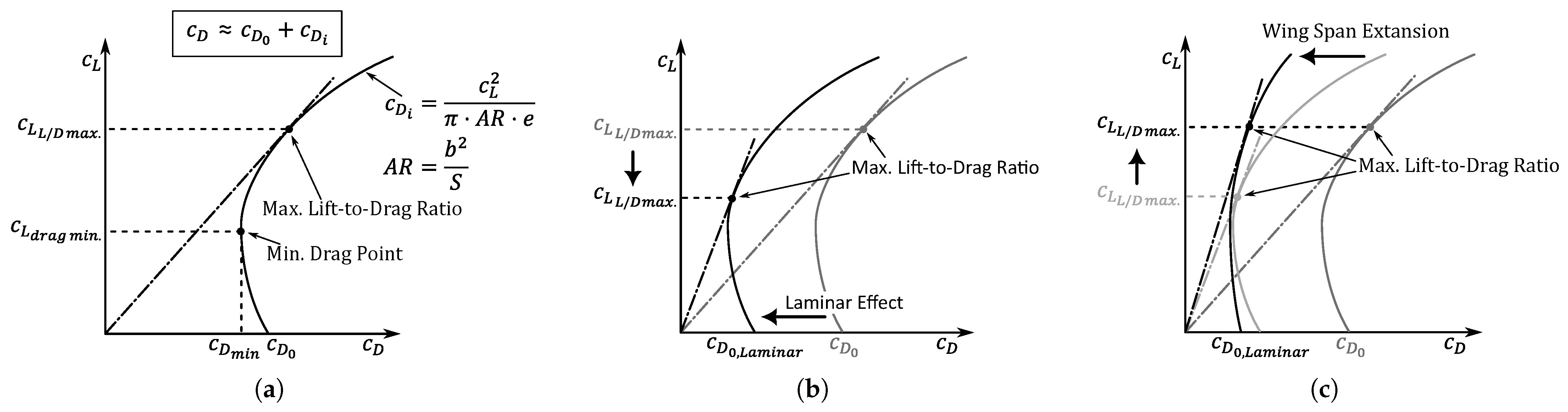
Figure 3 illustrates the approach used.
Figure 3a (left) shows a typical, although simplified, aerodynamic polar with its main contributors of friction drag and induced drag. The induced drag, which is driving the curvature of the aerodynamic polar, depends on the lift coefficient and the aspect ratio of the wing. As soon as the laminar-flow technologies are integrated, the aerodynamic polar shifts to the right, as shown in the middle
Figure 3b. Due to the shift in polar to the right, the lift coefficient at which the maximum lift-to-drag ratio (LoD) is located is reduced. However, the wing design was performed with the previous lift coefficient at the maximum LoD. This indicates a margin to increase the lift coefficient to the same level as before. Several approaches can be used to increase the aircraft’s lift coefficient at maximum LoD, such as increasing the flight altitude or changing the wing aspect ratio. The change in flight altitude would improve the aircraft’s aerodynamic performance but would require a different engine design and increase thrust requirements at the top of climb. The other option is to change the aspect ratio of the wing. The wing area depends on the approach and landing requirements, which prohibit a reduction. With a larger aspect ratio for a given wing area, not only is the lift coefficient at maximum LoD increased, but also the induced drag is reduced, thereby improving the aircraft’s performance.
3. Results
The first step in the design of the Laminar Aircraft is the step-wise integration of laminar-flow technologies into each component. This is done to better understand the technology and to identify potential challenges or design drivers.
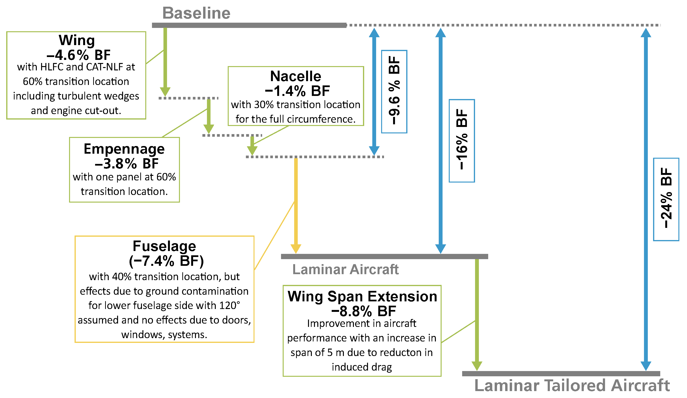
Figure 4 shows this step-wise integration, starting with the laminarisation of the wing, followed by the empennage, nacelle, and fuselage, and finally the wing planform adaptation. The ladder chart starts with the turbulent baseline aircraft and then evaluates each component independently. First, the wing is equipped with an HLFC system on the inner and outer wings, as well as NLF on the wing tips. Together, a 4.6% reduction in block fuel was achieved for the design mission. The empennage design incorporates a single HLFC panel for each of the VTP and HTP, resulting in a 3.8% block fuel reduction. The nacelle has HLFC for the full circumference up to a 30% transition point, resulting in a 1.4% reduction in block fuel. This is considered achievable based on extensive experience from previous projects. The last component, the fuselage, shows a large potential to reduce fuel consumption by 7.4%. However, there are large uncertainties as this technology has many open questions. Some of the major challenges to be solved include the complex fuselage nose and cockpit area, the integration of instrumentation, and the handling of doors and windows.
Tailoring the wing planform for laminar flight further improves performance. As can be seen, the span extension further reduces fuel consumption by 8.8% with a wing span extension of 5 m. However, this estimate is optimistic as it relies on conceptual design methods that do not fully account for the complexities of wing design. This improvement is due to the increase in aspect ratio, which reduces induced drag. As a result, the laminar-tailored aircraft reduces fuel consumption by 24% compared to the turbulent baseline aircraft. It should be noted that this comparison of the laminar-tailored aircraft with the baseline aircraft of different span is not equitable, since the baseline aircraft could have a span extension and the associated reduction in induced drag.
To provide a more comprehensive overview of the different configurations,
Table 2 lists the key aircraft characteristics and compares four different configurations, i.e., the baseline (B.S0), the baseline with 5 m span increase (B.S5), the laminar design (L.S0), and the laminar tailored design with 5 m span increase (L.S5). The two configurations with the original span (L.S0-B.S0) are compared, then the two configurations with the increased span (L.S5-B.S5), and finally the laminar-tailored aircraft with the span extended to the baseline with the original span (L.S5-B.S0). Considering the block fuel consumption for the design mission, it shows the 16% and 24% reduction in fuel consumption for the laminar aircraft, as already shown in the ladder chart in
Figure 4. As mentioned earlier, the comparison between the Baseline (B.S0) and the Laminar Tailored Aircraft (L.S5) with span extension is not equitable. Therefore, to be more comparable, the baseline was given an equivalent span extension (L.S5-B.S5) and shows a 13% reduction in fuel consumption. The lower fuel reduction of the L.S5-B.S5 case compared to the L.S0-B.S0 case can be explained by several phenomena. One explanation is the already significant performance improvement from the 5 m span increase, which reduces wing area, engine size, mass, and power requirements for any additional systems for the laminar technologies. When laminar technologies are integrated in the next step, the change in performance is not as great as before, and the compounding of the different effects is not as strong. Especially for the wing, the laminar effect is greater for large wetted areas. As the wing area decreases with increasing span to maintain the same approach speed, the percentage benefit of laminar aerodynamics on the wing decreases compared to the other components.
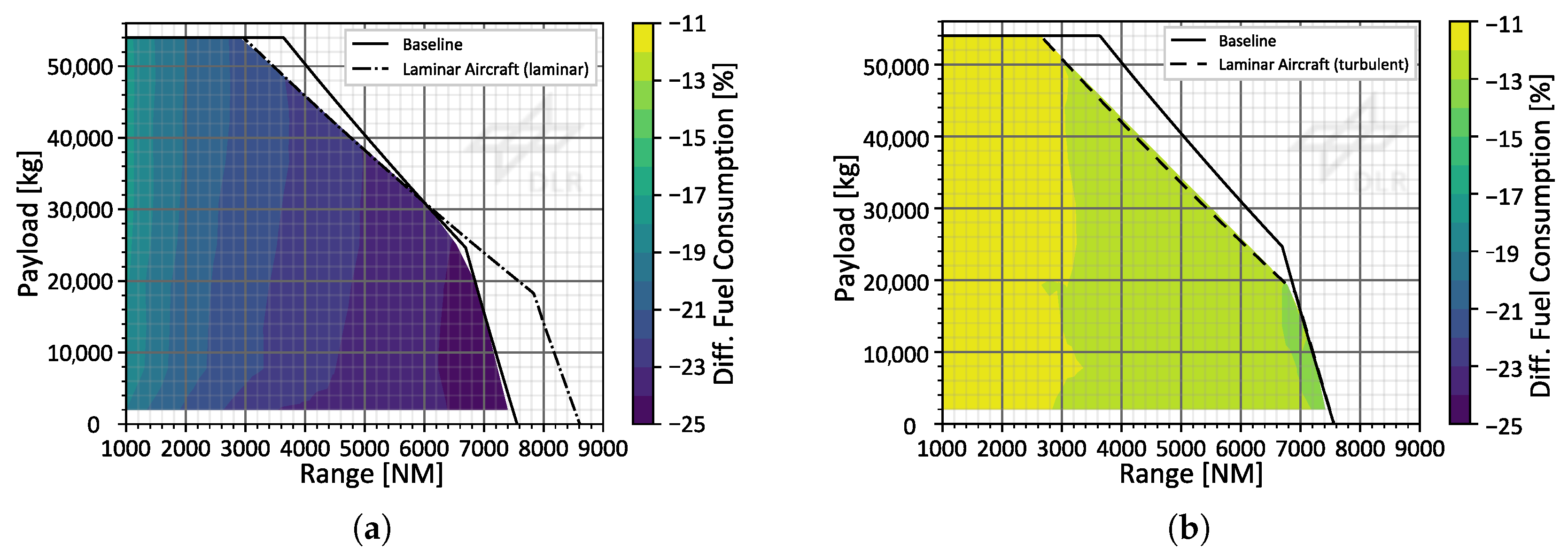
The overall performance of different payload and range combinations is analysed in
Figure 5. The two different aircraft configurations, the baseline and the laminar design, are compared with the relative difference in fuel consumption. A negative value indicates a reduction in fuel consumption for the laminar aircraft and vice versa. In addition, the laminar aircraft can be operated differently. In the best case, the HLFC system operates normally, and the full benefits of laminar aerodynamics can be achieved. However, in the worst case, the HLFC system fails for the entire mission and the laminar aircraft is operated with turbulent aerodynamics.
Figure 5a compares the baseline and the aircraft with laminar aerodynamics. It shows that a reduction between 17% and 24% is possible, mainly depending on the range. If the laminar technologies fail and the same laminar aircraft can only be operated with turbulent aerodynamics (see
Figure 5b), then the fuel consumption benefit is reduced to approximately 11 to 13%. This means that even when an aircraft design incorporating laminar-flow technologies is operated under turbulent conditions, its performance is still superior to that of the turbulent baseline design with the same technology assumptions. However, a disadvantage of this laminar aircraft design is that the design mission of 6000 NM and 31 t payload is no longer feasible, thereby reducing operational flexibility. A maximum range of approximately 5400 NM can be observed for the laminar aircraft with a failed HLFC system at design payload.
4. Conclusions
The systematic integration of natural and hybrid laminar flow control applied to the wing, empennage, nacelle and fuselage has been shown to deliver a fuel reduction of around 16%. When the wing aspect ratio is concurrently adjusted to match the lift coefficient at maximum LoD, this fuel reduction increases to 24%. These findings confirm the central hypothesis of the DLR LamTA project, namely, that an early-stage, systems-level consideration of laminar-flow technologies is essential for a comprehensive understanding of the technology and for estimating efficiency gains at the aircraft level. While the present results provide a first-order benchmark, several opportunities for refinement remain. Future work will involve more detailed disciplinary analyses, including refined, high-fidelity aerodynamics, advanced structural optimisation, propulsion integration, and control-system modelling. Addressing these aspects will validate the preliminary gains reported in this work.



 ,
,