Proceeding Paper

Development and Integration of a Flight Dynamics Module into the ODE4HERA Open Digital Platform †

by
Danilo Ciliberti
*,
Agostino De Marco
and
Fabrizio Nicolosi
Department of Industrial Engineering, University of Naples Federico II, Via Claudio 21, 80125 Napoli, Italy
*
Author to whom correspondence should be addressed.
Presented at the 15th EASN International Conference, Madrid, Spain, 14–17 October 2025.
Eng. Proc. 2026, 133(1), 63; https://doi.org/10.3390/engproc2026133063
Published: 30 April 2026

Abstract

The pursuit for cleaner aviation pushes research in hybrid-electric aircraft, which are far more complex systems than conventional airplanes. In this respect, the ODE4HERA European project aims to accelerate the development of such systems with the implementation of a solution-neutral Open Digital Platform, driving the design from top level requirements to virtual verification and validation. In this respect, the authors developed and integrated a flight dynamics module in a co-simulation environment aiming at the performance verification of the reference hybrid-electric aircraft through flight simulation. The implementation of a point mass model was sufficiently accurate to comply with the preliminary objectives of the project, paving the way for a higher-fidelity and more complex flight dynamics and control systems.

1. Introduction

Recent trends in aviation demonstrate an industry-wide shift towards climate-neutral solutions, with Hybrid-Electric Regional Architecture (HERA) positioned at the forefront of next-generation short-range air transport. The move towards hybrid-electric architectures introduces an unprecedented level of complexity, far surpassing that of traditional aircraft systems. Comparative analyses indicate that hybrid-electric powertrains may require handling over twice the number of parameters and several times more combinations than conventional systems [1]. This complexity necessitates innovative methodologies for the design and certification of such aircraft.
Responding to these challenges, the EU-financed ODE4HERA project [2]—initiated in January 2024—aims to accelerate the development of HERA models, realizing a 50% increase in cost-effectiveness and a 50% reduction in development lead times with respect to the 2020 state of the art. This will be achieved with the development of an Open Digital Platform (ODP), a tool-agnostic environment integrating software and methods with Model-Based System Engineering (MBSE), exchanging data through SysML v2 language [3], and providing design, optimization, and virtual verification and validation (V&V) processes. The integrated V&V phase will allow us to virtually test the entire system and its subsystem with high-fidelity methods before the aircraft is manufactured, anticipating design flaws before their occurrence in experimental tests or flight operations.
The application case 1 of the project aims to: develop behavioral models of aircraft systems; integrate such models into a co-simulation environment; execute the V&V process; and perform multi-disciplinary optimization (MDO). This paper presents the development of a flight dynamics module aiming at the simulation of a typical flight mission of the reference hybrid-electric aircraft within a co-simulation environment.
Flight simulation can be mainly modeled with either point mass or 3–6 degrees of freedom (DOF) models. The former offers computational efficiency and sufficient accuracy for long-range, minimally maneuvered profile analysis, making them ideal for mission planning and fuel estimation. The latter deliver greater fidelity for dynamic maneuvers, control system performance evaluation, and training applications, but with higher modeling complexities and at higher computational costs. It was shown that a point mass model coupled with performance-based climb and descent modules can accurately reproduce mission performance within 3% error for regional transports [4].
The project consortium expects high-fidelity simulations to demonstrate the capability of the ODP to perform the integrated V&V phase with realistic models of the system of interest. Ideally, a behavioral model of a human pilot, at least for longitudinal (3-DOF) aircraft control, would be preferred. An example of such kind of controller is the Total Energy Control System (TECS), introduced by Lambregts in the early 1980s [5,6,7]. TECS acts like a human pilot, coordinating flight path and airspeed control by simultaneously controlling elevator and throttle. Some examples are given in [8,9,10,11,12,13,14,15,16], while an application in a hybrid-electric regional aircraft was performed by the authors in [17].
In the remainder of the paper, a detailed description of the point mass model and its implementation will be given. The results of the co-simulation with other subsystems will be presented, followed by a short discussion on the issues in moving towards the TECS model. Conclusions will recap the main findings of this work.

2. Flight Dynamics Model

The development of the flight dynamics module has been performed in MATLAB/Simulink R2024b. Its integration in the co-simulation environment, which gathers the modules developed by project partners—propulsive plant, electric machines, mission control—is done in Simcenter Amesim or Simcenter System Architect. Although the latter provides the possibility of directly integrating a Simulink file, a Functional Mock-up Interface (FMI) is needed to keep a solution-neutral architecture. FMI is an open, tool-independent standard for exchanging and integrating dynamic simulation models between different software tools packaged as Functional Mock-up Units (FMUs), which substantially are black boxes containing the solver, the model’s parameters, and input/output ports [18]. Thus, at the end of its development, the flight dynamics module is converted into an FMU.
While the FMU provides a standardized package to integrate the simulation model in a co-simulation environment, the flight dynamicist must develop such a model considering the available input and the expected output signals. In our case, the thrust vector and fuel consumption are provided by the propulsive module and the attitude is controlled by the commanded signal of the angle of attack. Additional variables could be provided for MDO activities. The required output signals are kinematic variables in the inertial North–East–Down (NED) reference frame, attitude angles (bank, flight path, heading), true airspeed, altitude, and air data (static and total pressure and temperature). To preliminarily validate the performance of the reference aircraft and to keep compatibility with the available modules and signals, it was decided to initiate the development and integration activities with a point mass model.
The aircraft motion is described by the Nonlinear Aircraft Performance Equations (NAPE), relating the true airspeed V, flight path angle γ , and heading angle δ to lift L, drag D, thrust T, mass m, and bank angle ν . The NAPE describe the three-dimensional translation of a point mass, representing the center of gravity of the aircraft. They are valid under the assumptions of no sideslip and thrust aligned with the velocity vector. They were adapted from [19] and listed here
                      V ˙ = T D m g sin γ
                                                    γ ˙ = 1 m V L cos ν m g cos γ
δ ˙ = L sin ν m V cos γ
where g is the gravitational constant fixed to 9.81 m/s2, with the hypothesis of a flat Earth. The time integration of (1) to (3) is not sufficient to completely describe the aircraft motion. Additional kinematic equations are necessary to relate the flight dynamics variables to the inertial coordinates
            x ˙ E , G = V cos γ cos δ
          y ˙ E , G = V cos γ sin δ
h ˙ = V sin γ
where x ˙ E , G , y ˙ E , G , and h are the North, East, and altitude distances, respectively, of the aircraft center of gravity with respect to an arbitrary origin on the Earth surface. However, only the longitudinal variables are needed to simulate a mission profile in our context. Therefore, the bank angle ν is null and the heading angle δ is an undefined constant assumed null for simplicity. Equations (1)–(6) are therefore reduced as follows
                                    V ˙ = T D m g sin γ
                                                  γ ˙ = 1 m V L m g cos γ
x ˙ E , G = V cos γ
          h ˙ = V sin γ
The adoption of the point-mass formulation, restricted here to purely longitudinal motion with zero bank and heading angles, inherently neglects lateral–directional dynamics such as Dutch roll, roll–yaw coupling, and sideslip effects. As a consequence, the model cannot capture phenomena associated with asymmetric thrust, crosswind conditions, or roll control activity, and it cannot be used to assess handling qualities or lateral stability margins. Moreover, transient manoeuvres involving strong coupling between attitude, angular rates, and translational motion (e.g., aggressive step commands) are only approximated through the evolution of flight path angle and speed, without resolving attitude dynamics or control surface deflections. These simplifications are acceptable in the present context, where the focus is on mission-level performance, energy consumption, and compatibility with the ODE4HERA V&V workflow, but they limit the validity of the results to non-aggressive, near-trim flight segments.
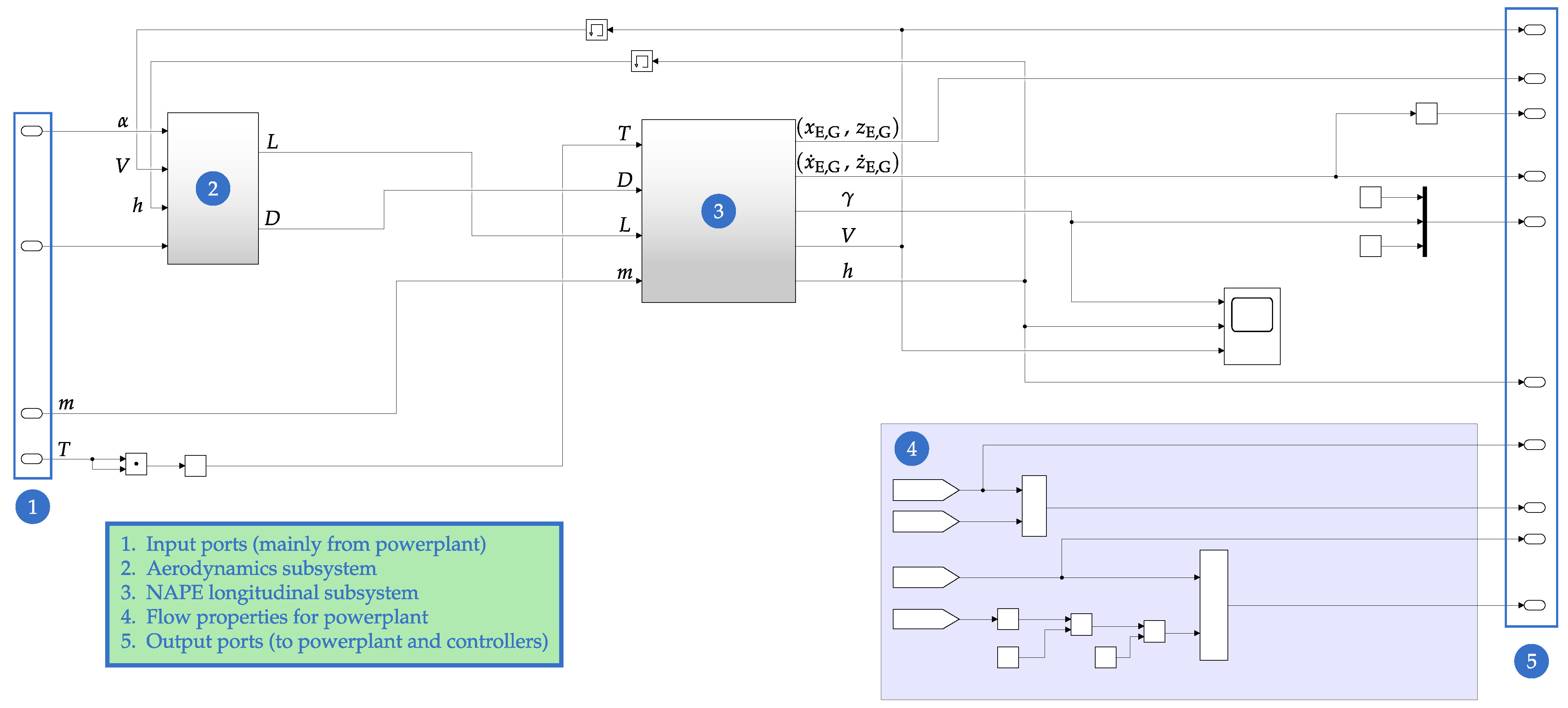
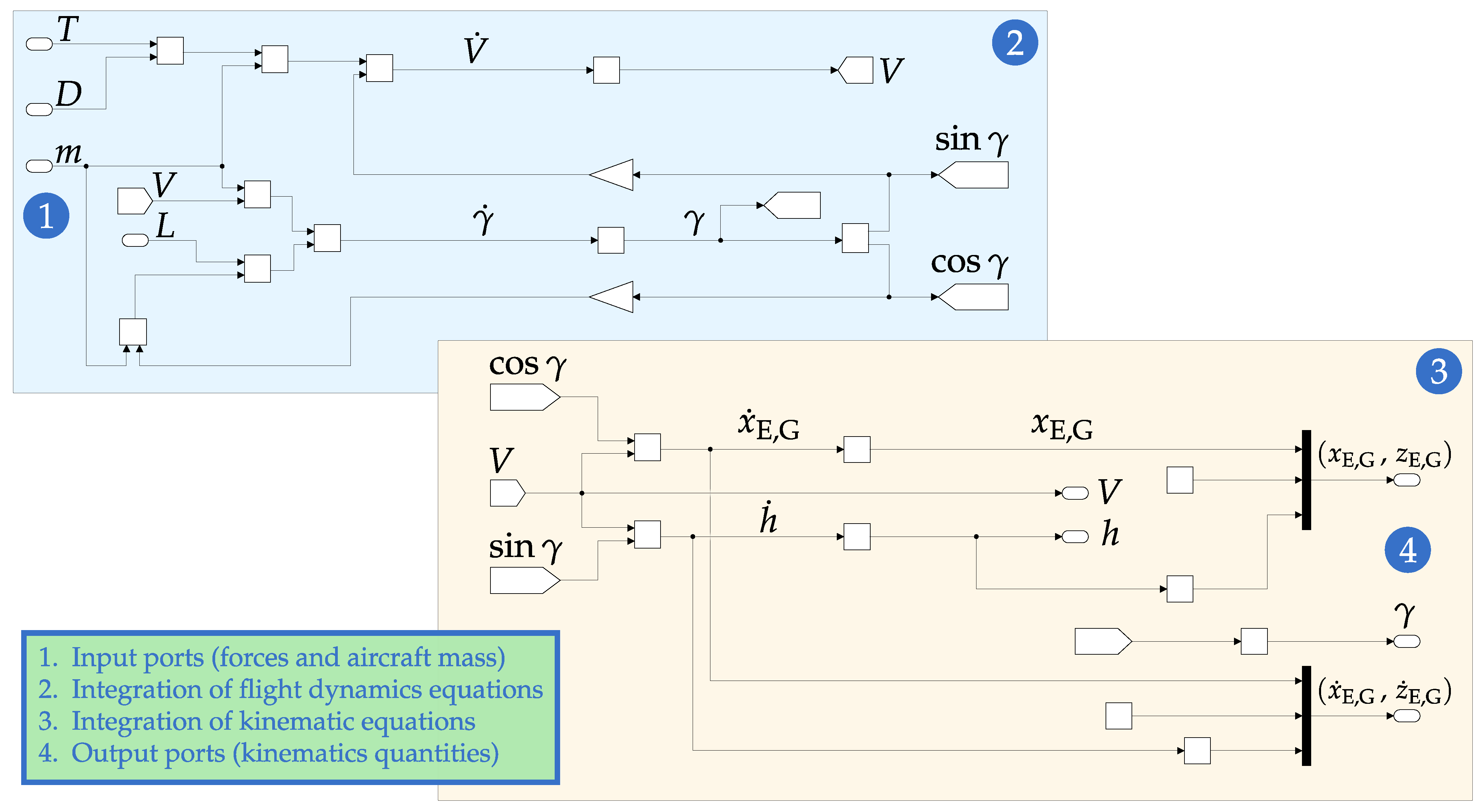
Equations (7)–(10) are integrated in Simulink and constitute the core of the flight dynamics module. The main Simulink mask is shown in Figure 1. It is made up of the three subsystems, Aerodynamics, NAPE, and Air Data. The first two are shown in Figure 2 and Figure 3, respectively. The aerodynamic model was provided by the HERA consortium [20] through a Cooperation Agreement and cannot be disclosed. However, the reference aircraft—named UERA—is based on the ATR-72, with a slightly larger wing aspect ratio and a hybrid-electric powerplant with thermal engines and batteries.
Finally, a co-simulation FMU 2.0 version is generated. When exporting the Simulink model as an FMU 2.0 for co-simulation, care must be taken to avoid discontinuities in the internal blocks, since most FMI-based environments assume continuous right-hand sides and version 2.0 cannot handle events to manage switch or if–else logic. In our first implementation, the standard Simulink ISA block caused small discontinuities, likely due to piecewise definitions of the atmospheric layers, and similar issues may arise from conditional aerodynamic lookup tables, engine deck ratings, and logical switches in controller blocks. To mitigate this, the tropospheric ISA model was recast as a smooth MATLAB function, discontinuous constructs were removed or replaced by continuously differentiable approximations, and algebraic loops where avoided by inserting delays (memory block) on feedback paths. This ensured a numerically robust FMU suitable for integration into Simcenter Amesim and other FMI-compliant tools.
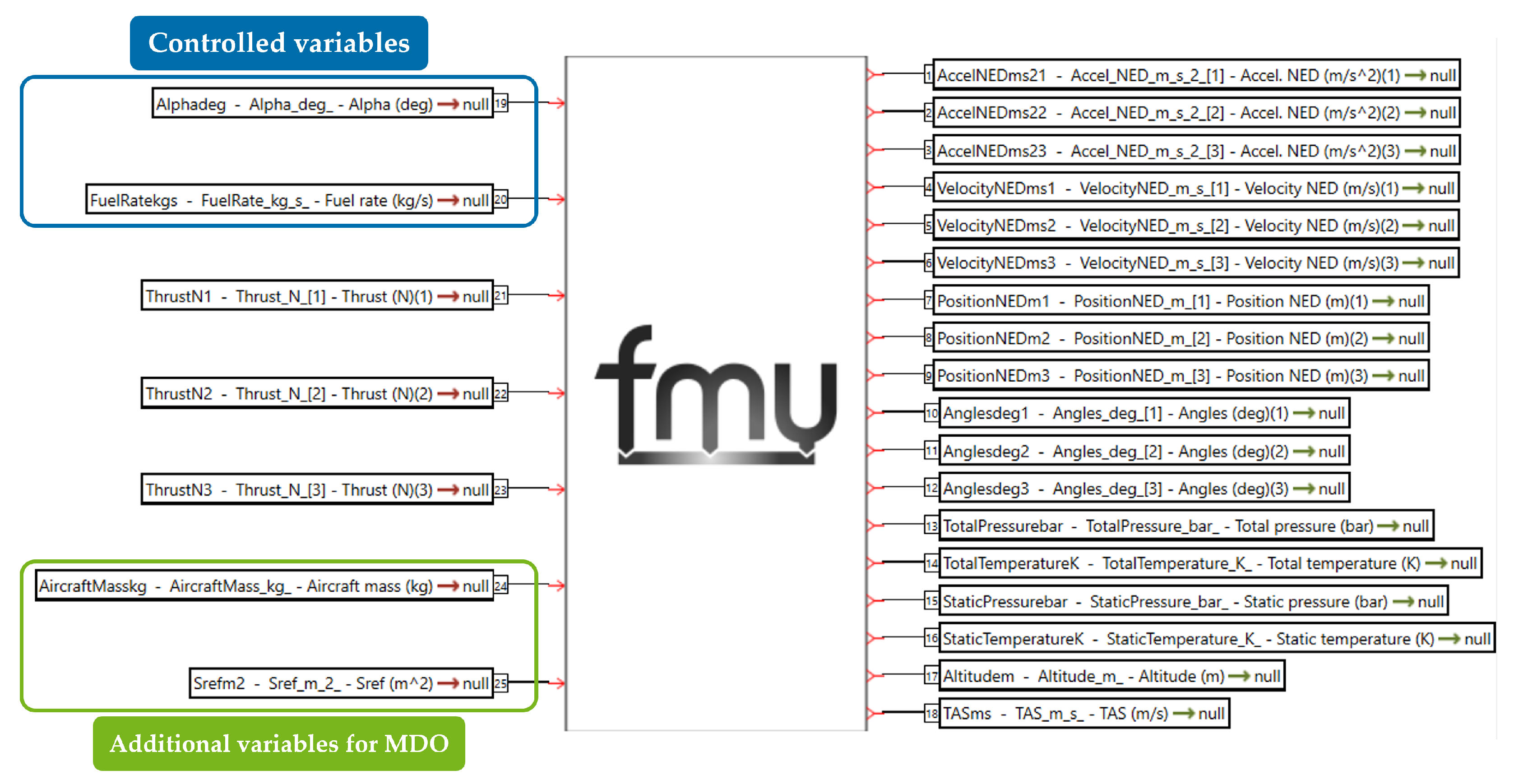
The representation of the FMU as imported into Simcenter Amesim 2310 is illustrated in Figure 4, where all the vector quantities are expanded, explicitly showing the three scalar components of thrust, acceleration, velocity, position, and attitude angles—bank, flight path, and heading. Lateral-directional variables are set to zero.

3. Results and Discussion

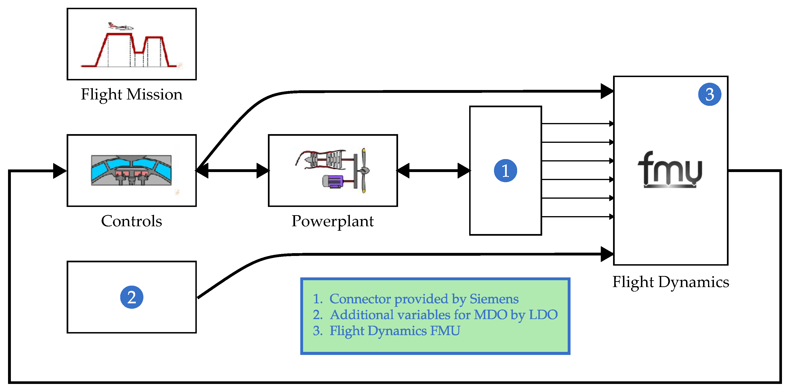
The co-simulation setup adopts a master algorithm in Simcenter Amesim 2310, which advances all subsystems with a fixed time step of 0.01 s. The same value is applied to the FMU, with an automatic selection of the solver. At each communication instant, the propulsive module provides the three-component thrust vector and instantaneous fuel flow to the flight dynamics FMU, and receives back total forces, kinematic states, and air data required for its performance maps. In parallel, the controller block—made of two single-input single-output (SISO) controllers, autopilot and autothrottle—reads altitude and true airspeed from the flight dynamics FMU and outputs commanded angle of attack and fuel flow modulation, which are routed respectively to the aerodynamic model (through the flight dynamics FMU) and to the propulsive system.
The integration of the FMU into Simcenter Amesim 2310 is shown in Figure 5. There are some features that required a custom-made interface. For instance, the propulsive module has ports that share multiple input and output signals. Also, each port may be of a different nature (e.g., mechanical) and it is not possible to simply demux the signals. In this respect, Siemens provided a connector to link the mechanical port of the propulsive module to the scalar ports of the flight dynamics FMU.
The test case here presented shows the integration of the flight dynamics module developed by the authors into a Simcenter Amesim file prepared by Leonardo Aircraft (LDO). Contributions of other partners are not visible at this stage. The integration of all the modules is out of the scope of this paper.
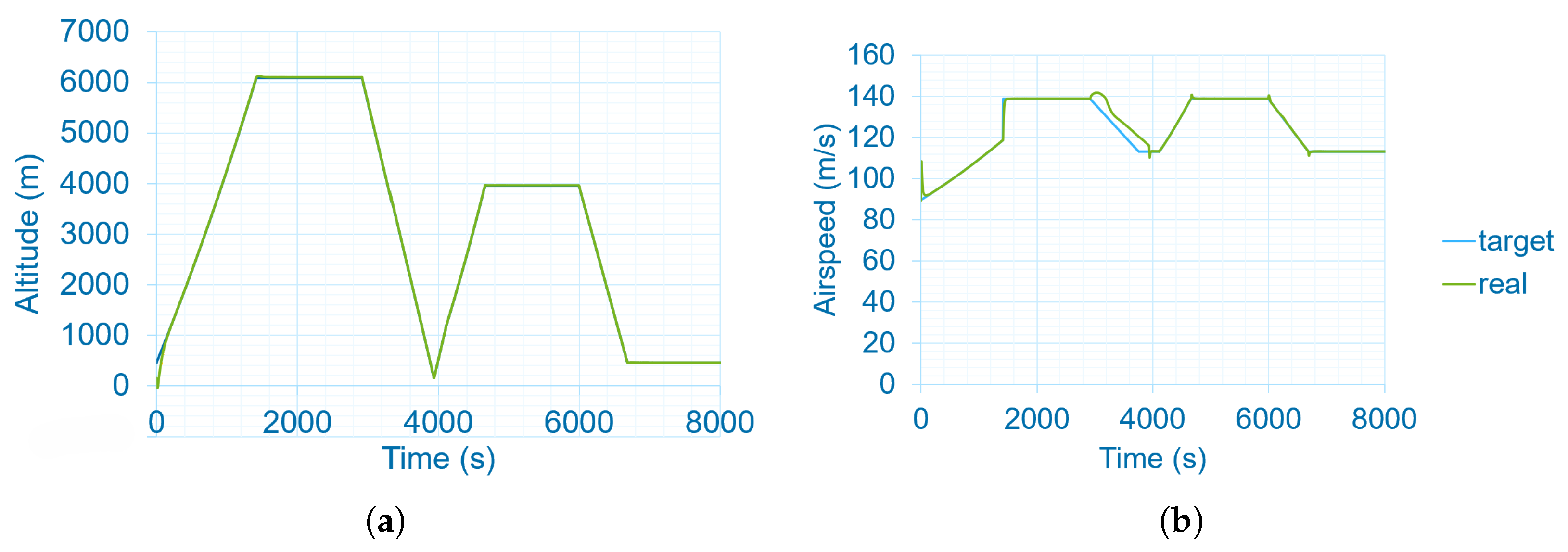
The mission profile is a sequence of climb, cruise, and descent phases, including an alternate route. Take-off and landing are not simulated. Results for such a mission are shown in Figure 6, where the actual (real) signals are compared with the target signals defined in the flight mission block. These two set of signals are almost completely overlapped, confirming the successful implementation of the flight dynamics module. Thus, such a model can be exploited later for the integrated V&V analysis.
However, in the first descent segment, the real airspeed exhibits a modest overshoot and a noticeable delay with respect to the target profile, while the altitude tracking remains accurate. This behaviour is consistent with the intrinsic coupling between flight path and speed in longitudinal motion: as the SISO altitude controller commands a negative flight path angle to initiate the descent, the available excess thrust momentarily accelerates the aircraft before the airspeed controller compensates through throttle reduction. The absence of a coordinated, energy-based allocation between elevator and thrust implies that altitude tracking is prioritised while speed is corrected with some lag, which explains why the phenomenon does not appear uniformly across all descent segments. Given the small magnitude of the overshoot and the mission-level focus of the present study, this performance has been deemed acceptable for preliminary V&V activities, although it clearly motivates the future implementation of the TECS control laws to achieve more pilot-like coordination of flight path and airspeed.

4. Conclusions and Future Works

A point mass flight dynamics model for the co-simulation and integration in the ODE4HERA EU project’s ODP has been developed in Simulink. The model proved to achieve the expected performance of the test case. Any change in aircraft characteristics (mass, wing area, aerodynamic data) can be quickly and automatically updated, so that the model is ready for the integrated V&V and MDO activities. As such, a sufficient level of compliance with the objective of the project’s application case has been achieved.
However, it would be interesting to develop an advanced longitudinal flight dynamics model with a high-fidelity flight control system mimicking human pilot behavior. The complexity of such a module together with its integration with other key systems—such as the hybrid-electric powertrain, with characteristics that may be unknown—pose a challenge in its implementation in the ODP, as the objective is a generalization of the V&V process.

Author Contributions

Conceptualization, D.C. and A.D.M.; methodology, D.C.; software, D.C.; validation, D.C.; formal analysis, D.C.; investigation, D.C.; resources, F.N.; data curation, D.C. and A.D.M.; writing—original draft preparation, D.C.; writing—review and editing, D.C. and A.D.M.; visualization, F.N.; supervision, A.D.M. and F.N.; project administration, F.N.; funding acquisition, F.N. All authors have read and agreed to the published version of the manuscript.

Funding

Co-Funded by the European Union (project number: 101140510). Views and opinions expressed are however those of the author(s) only and do not necessarily reflect those of the European Union or Clean Aviation Joint Undertaking. Neither the European Union nor the granting authority can be held responsible for them.

Data Availability Statement

Restrictions apply to the availability of these data. Except for those shown in the paper, data were obtained from the HERA consortium and are not available for release.

Acknowledgments

The project ODE4HERA is supported by the Clean Aviation Joint Undertaking and its members.

Conflicts of Interest

The authors declare no conflicts of interest. The funders had no role in the design of the study; in the collection, analyses, or interpretation of data; in the writing of the manuscript; or in the decision to publish the results.

Abbreviations

The following abbreviations are used in this manuscript:
DOFDegrees Of Freedom
EUEuropean Union
FMIFunctional Mock-Up Interface
FMUFunctional Mock-Up Unit
HERAHybrid-Electric Regional Architecture
ISAInternational Standard Atmosphere
LDOLeonardo company
MBSEModel-Based System Engineering
MDOMulti-Disciplinary Optimization
NAPENonlinear Aircraft Performance Equations
NEDNorth–East–Down
ODE4HERAOpen Digital Environment for Hybrid-Electric Regional Architectures
ODPOpen Digital Platform
PIDProportional Integral Derivative
SISOSingle-Input Single-Output
TECSTotal Energy Control System
V&VVerification and Validation

References

  1. Deutsches zentrum fur Luft- und Raumfahrt EV (DLR, Linder Hohe, Koln 51147, Germany) et al. Grant Agreement Project 101140510—ODE4HERA. Unpublished Work.
  2. Open Digital Environment for Hybrid-Electric Regional Architectures. Available online: https://cordis.europa.eu/project/id/101140510 (accessed on 16 November 2025).
  3. SysML v2 Specification—Next Generation MBSE Modeling. Available online: https://www.omg.org/sysml/sysmlv2/ (accessed on 11 November 2025).
  4. Grazioso, G.; De Marco, A.; Della Vecchia, P.; Di Stasio, M.; Trifari, V.; Nicolosi, F. A simulation-based mission optimization approach for regional transport hybrid-electric aircraft. Appl. Energy 2025, 402, 126869. [Google Scholar] [CrossRef]
  5. Lambregts, A.A. Vertical Flight Path and Speed Control Autopilot Design Using Total Energy Principles. In Proceedings of the Guidance and Control Conference; American Institute of Aeronautics and Astronautics: Reston, VA, USA, 1983. [Google Scholar] [CrossRef]
  6. Amelink, M.; Mulder, M.; Van Paassen, M.M.; Flach, J. Theoretical Foundations for a Total Energy-Based Perspective Flight-Path Display. Int. J. Aviat. Psychol. 2005, 15, 205–231. [Google Scholar] [CrossRef]
  7. Lambregts, A.A. TECS Generalized Airplane Control System Design—An Update. In Advances in Aerospace Guidance, Navigation and Control; Springer: Berlin/Heidelberg, Germany, 2013; pp. 503–534. [Google Scholar] [CrossRef]
  8. Bruce, K.; Kelly, J.; Person, L., Jr. NASA B737 flight test results of the Total Energy Control System. In Proceedings of the Astrodynamics Conference; American Institute of Aeronautics and Astronautics: Reston, VA, USA, 1986. [Google Scholar] [CrossRef]
  9. Bruce, R. NASA B737 Flight Test Results of the Total Energy Control System; Technical Report, NASA-CR-178285; Boeing Commercial Airplane Company: Renton, WA, USA, 1987. [Google Scholar]
  10. Faleiro, L.; Lambregts, A. Analysis and tuning of a ‘Total Energy Control System’ control law using eigenstructure assignment. Aerosp. Sci. Technol. 1999, 3, 127–140. [Google Scholar] [CrossRef]
  11. Shevchenko, A.M. Energy-based approach for flight control systems design. Autom. Remote Control 2013, 74, 372–384. [Google Scholar] [CrossRef]
  12. Jimenez, P.; Lichota, P.; Agudelo, D.; Rogowski, K. Experimental Validation of Total Energy Control System for UAVs. Energies 2020, 13, 14. [Google Scholar] [CrossRef]
  13. Comer, A.; Chakraborty, I. Total Energy-Based Control Design and Optimization for Lift-Plus-Cruise Aircraft. J. Guid. Control Dyn. 2024, 47, 1414–1436. [Google Scholar] [CrossRef]
  14. Comer, A.M.; Chakraborty, I. Full Envelope Flight Control System Design and Optimization for a Tilt-Wing Aircraft. J. Am. Helicopter Soc. 2024, 69, 1–18. [Google Scholar] [CrossRef]
  15. Comer, A.M.; Bhandari, R.; Putra, S.H.; Chakraborty, I. Design, Control Law Development, and Flight Testing of a Subscale Lift-Plus-Cruise Aircraft. In Proceedings of the AIAA SCITECH 2024 Forum; American Institute of Aeronautics and Astronautics: Reston, VA, USA, 2024. [Google Scholar] [CrossRef]
  16. Molino, L.; De Marco, A.; Manfredi, S. Energy-based Multiple-Input-Multiple-Output nonlinear control of fixed-wing aircraft. In Advances in Nonlinear Dynamics. Proceedings of the Fourth International Nonlinear Dynamics Conference (NODYCON 2025); Springer: Berlin/Heidelberg, Germany, 2026; In press. [Google Scholar]
  17. Ciliberti, D.; De Marco, A. Nonlinear Control Strategies in a Co-Simulation Framework for Hybrid Regional Aircraft Design Verification. In Advances in Nonlinear Dynamics. Proceedings of the Fourth International Nonlinear Dynamics Conference (NODYCON 2025); Springer: Berlin/Heidelberg, Germany, 2026; In press. [Google Scholar]
  18. Functional Mock-Up Interface. Available online: https://fmi-standard.org/ (accessed on 15 November 2025).
  19. Schmidt, D. Modern Flight Dynamics, 1st ed.; McGraw-Hill: New York, NY, USA, 2011. [Google Scholar]
  20. Hybrid-Electric Regional Architecture. Available online: https://cordis.europa.eu/project/id/101102007 (accessed on 16 November 2025).
Figure 1. The main mask of the Simulink model.
Engproc 133 00063 g001
Figure 2. The mask of the aerodynamics block.
Engproc 133 00063 g002
Figure 3. The mask of the NAPE block.
Engproc 133 00063 g003
Figure 4. The mask of the FMU as imported into Simcenter Amesim 2310.
Engproc 133 00063 g004
Figure 5. Schematics representation of the FMU integrated into Simcenter Amesim 2310.
Engproc 133 00063 g005
Figure 6. Time histories: (a) altitude; (b) airspeed. The overlapped lines represent the achievement of the target trajectory. Some deviations are possible.
Engproc 133 00063 g006
Disclaimer/Publisher’s Note: The statements, opinions and data contained in all publications are solely those of the individual author(s) and contributor(s) and not of MDPI and/or the editor(s). MDPI and/or the editor(s) disclaim responsibility for any injury to people or property resulting from any ideas, methods, instructions or products referred to in the content.