Proceeding Paper

Vibration-Based Damage Detection and Localisation on a Trainer Jet Aircraft Wing †

by
Gabriele Dessena
1,*,
Marco Civera
2,
Andrés Marcos
1,
Bernardino Chiaia
2 and
Oscar E. Bonilla-Manrique
3
1
Department of Aerospace Engineering, Universidad Carlos III de Madrid, Avenida de la Universidad 30, Leganés, 28911 Madrid, Spain
2
Department of Structural, Geotechnical and Building Engineering, Politecnico di Torino, Corso Duca degli Abruzzi 24, 10129 Turin, Italy
3
Electronic Technology Department, Universidad Carlos III de Madrid, Avenida de la Universidad 30, Leganés, 28911 Madrid, Spain
*
Author to whom correspondence should be addressed.
Presented at the 15th EASN International Conference, Madrid, Spain, 14–17 October 2025.
Eng. Proc. 2026, 133(1), 44; https://doi.org/10.3390/engproc2026133044

Published: 27 April 2026

Abstract

Damage detection and identification are important for many aerospace and aeronautical structures. Vibration-based methods check changes in modal parameters, such as natural frequencies and mode shapes, usually indicating damage. For large structures, comparing each mode and parameter separately is impractical. This study proposes the modified total modal assurance criterion (MTMAC) as a single index for damage detection. To provide localisation, MTMAC is paired with the coordinate modal assurance criterion (COMAC), a standard tool for locating damage using mode shapes. Accurate modal identification is required to support structural health monitoring (SHM). For this purpose, the recently introduced improved Loewner Framework (iLF) is used. Noting that this is its first application to SHM, its performance on an undamaged BAE Systems Hawk T1A jet trainer wing is compared with literature results. Then, the iLF is applied to damaged states of the same airframe. In all cases, the aircraft vibration testing is carried out under multiple-input, multiple-output conditions. The identified modal sets are used to compute the MTMAC for detection and severity, and COMAC for localisation. Results show that the iLF provides robust modal identification for SHM and that the MTMAC effectively detects damage.

1. Introduction

Damage is any structural change that degrades the operational capacity of a system [1], and structural health monitoring (SHM) is known as the field that aims at developing and implementing methods to detect such changes in aerospace, civil, or mechanical systems. Being able to detect early damage or anomalies can bring an operational advantage, decreasing downtime and increasing maintenance scheduling efficiency. Thus, SHM is of great interest for any aeronautical application. In vibration-based SHM, modal parameters, such as natural frequencies ω n , damping ratios ζ n , and mode shapes ϕ n , are common indicators [2]. Shifts in ω n can show severity effectively, but localise poorly due to environmental and operational variability. ϕ n allow damage localisation by comparing baseline and damaged states and can inform severity with the amplitude of the change. ζ n are seldom reliable alone because of strong dependence on non-structural factors. However, even when only considering ω n and ϕ n , their comparison between baseline and damaged data can become confusing and show ambiguous results of difficult interpretation for large systems. As discussed in the literature, modal parameters can be extracted in either controlled experimental scenarios, known as experimental modal analysis, and ambient or operational conditions, known as operational modal analysis (OMA). Please note that in aeronautics, the terms EMA and ground vibration testing (GVT) are sometimes used interchangeably, although they are distinct [3]. Despite more advanced approaches emerging recently, an unequivocal solution for SHM does not yet exist [4]. Furthermore, in aerospace and aeronautical engineering, most applications focus on the analysis of small subsystems, rather than full or partial airframes, despite very early efforts [5]. This results in the lack of suitable datasets to develop or improve SHM techniques, even more so when considering different experimental or operational setups. A notable exception is the single-input, multiple-output (SIMO) test dataset of a flexible wing with simulated damage in [6,7]. However, this does not cover other types of tests, such as multiple-input, multiple-output (MIMO) and OMA. The former was recently addressed by the Laboratory for Verification and Validation (LVV) at the University of Sheffield, which shared an open dataset of a vast MIMO EMA campaign for a full-scale BAE Systems Hawk T1A jet trainer [8,9], including healthy and damaged cases at different amplitudes.
Given the general lack of MIMO-based vibration-based damage detection and the ambiguity of sparse modal parameters comparison, this work proposed a two-step damage detection framework to be applied to large-scale structures: (i) the iLF for the identification of modal parameters and (ii) the modified total modal assurance criterion (MTMAC), formerly widely employed in finite element model updating [10], as a unique damage index informed by the parameters identified in (i). The rationale is that using the MTMAC allows condensing the information from multiple modes and ϕ n degrees of freedom in a single value; thus, allowing for a greater interpretability of modal parameters changes. To validate this approach, the study aims to achieve the following objectives:
  • Validate the iLF modal identification precision and accuracy within SHM;
  • Show that the MTMAC can be a valid and accurate damage index;
  • Apply the two-step damage detection strategy to a BAE Systems Hawk T1A wing.
For completeness of the damage detection process, the coordinate modal assurance criterion (COMAC) [11] is used to detect the variation in the mode shape trajectory.

2. Materials and Methods

2.1. BAE Systems Hawk T1A

The BAE Systems Hawk T1A experimental dataset, containing GVT data from 216 MIMO tests, was released by the Dynamics Research Group at the University of Sheffield [8,9]. This includes several damage scenarios, either simulated by local mass addition and/or the removal of wing panels, excitation input types, and amplitudes. The decommissioned jet trainer aircraft, once serving for the British Royal Air Force, is instrumented with 85 PCB Piezotronics (uniaxial and triaxial) accelerometers, along with other sensors (fibre-Bragg grating strain gauges, temperature sensors, etc.), totalling 139 channels. The airframe is fitted with five TiraTM TV 51140-MOSP modal shakers (https://www.tira-gmbh.de/fileadmin/inhalte/download/schwingprueftechnik/schwingpruefanlagen/modal/100N_bis_2700N/Datenblatt_system_tv_51140-MOSP_V07.pdf (accessed on 1 September 2024)), attached to PCB PiezotronicsTM 208C02 force transducers (https://www.pcb.com/products?m=208c02 (accessed on 1 September 2024)). For the scope of this work, only three tests are considered:
  • A healthy state at 0.5 V white Gaussian noise (WGN) input (case 1);
  • Two simulated damage states with progressive mass addition (616.8 and 916.8 g) on the port wing (PW_TLE) at 0.5 V WGN input (cases 2 and 3).
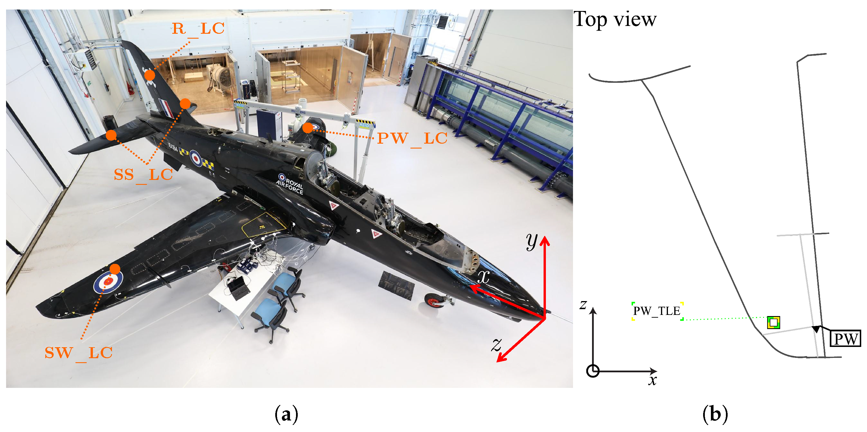
For all cases, the excitation bandwidth is between 5 and 256 Hz. The aircraft and the positions of the modal shakers are shown in Figure 1a, while the mass addition location on the port wing is displayed in Figure 1b.
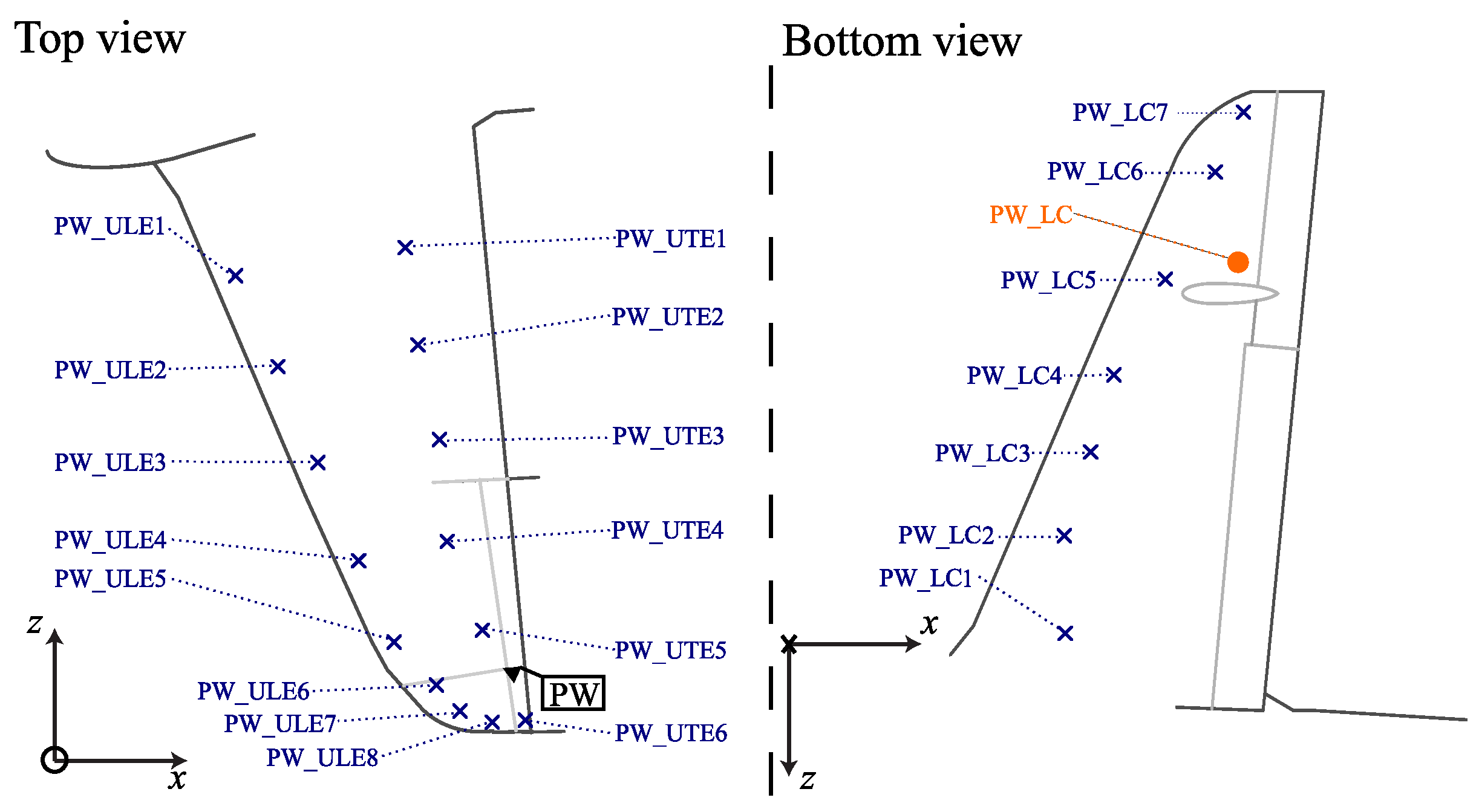
For our purposes, only the accelerometers mounted on the port wing are considered; this means that 21 acceleration output channels are used for the analysis. However, all five shakers, including those not on the wing, are used as inputs. Figure 2 shows the placement of the sensors along the port wing.
The dataset acceleration and force (from the transducers on the shakers) time series are sampled at f s = 2048 Hz. Notably, each of the 216 tests contains 10 realisations of the same test. So, for each test, ten MIMO frequency response functions (FRFs) are derived using the cross-spectral densities and averaged across the realisations (keeping the MIMO configuration) to increase the signal-to-noise ratio (SNR). These averaged FRFs are used for the system identification.

2.2. The Loewner Framework

The Loewner framework (LF) originated as a model order reduction (MOR) approach for MIMO dynamical systems, with roots in Charles Loewner’s 1930s introduction of the namesake Loewner interpolation matrix, L Antoulas et al. [12] developed a MOR formulation using tangential interpolation (i.e., rational interpolation along tangential directions) by solving the system realisation problem. The framework was subsequently employed for system identification in electronic applications. More recently, the LF has been adapted to extract modal parameters for SIMO vibration-based SHM in the frequency domain [13] to address ill-conditioning in conventional fitting procedures.
Formally, the LF considers a linear time-invariant system Σ in continuous-time descriptor form, with k internal variables and dimensions m inputs and p outputs:
Σ : E d d t x ( t ) = A x ( t ) + B u ( t ) , y ( t ) = C x ( t ) + D u ( t ) ,
where x ( t ) R k × 1 is the internal state, u ( t ) R m × 1 represents the input, and y ( t ) R p × 1 is the output and the corresponding system matrices are:
E , A R k × k , B R k × m , C R p × k , D R p × m .
When, for a finite value λ , the matrix ( A λ E ) is non-singular (with λ C ), the Laplace transfer function H ( s ) of Σ is expressed as:
H ( s ) = C s E A 1 B + D .
Using tangential interpolation, the LF fits FRF data to the transfer function H ( s ) . Its goal is similar to classical approaches such as rational fraction polynomials, but the use of tangential directions typically reduces computational cost. A rigorous overview is given in [12], while recent studies in modal analysis emphasise extracting modal parameters from MIMO systems [14]. The latter approach is used in this work, meaning that the modal parameters are extracted from eigenanalysis of the realised system matrices.

2.3. Damage Assessment, Quantification, and Localisation

Damage is inferred from shifts in ω n between a baseline and a later state; larger difference between two sets of ω n generally implies greater severity. Localisation follows from comparing baseline and damaged ϕ n ; departures from the baseline shape indicate likely damage sites. These principles are standard, yet direct comparisons become hard to interpret for complex structures. To couple ω n and ϕ n information in a single index, the complement of the MTMAC is adopted, pairing the ω n and ϕ n contributions to assessment and quantification:
MTMAC = 1 i = 1 n MAC ( ϕ i E , ϕ i N ) 1 + ω i N ω i E ω i N + ω i E
with i the mode of interest and E, N the baseline and damaged conditions. The MAC is defined as [15]:
MAC ( i , j ) = ( ϕ i E ) T ( ϕ j N ) 2 ( ϕ i E ) T ( ϕ i E ) ( ϕ j N ) T ( ϕ j N )
Since the MTMAC complement depends on both ω n and ϕ n , its value decreases as the damaged modal parameters deviate from the baseline due to local mass or stiffness changes.
For localisation, the COMAC, which measures local sensitivity between two sets of ϕ n , is used:
COMAC ( p ) = i = 1 n ( ϕ p , i E ) ( ϕ p , i N ) 2 i = 1 n ( ϕ p , i E ) 2 i = 1 n ( ϕ p , i N ) 2
where p denotes the corresponding DoF.

3. Results

Before assessing the SHM capability of the proposed two-step procedure, it is important to validate the BAE System Hawk T1A port wing modal identification of the healthy state against results available in the literature for the 0.4 V input case [14]. So, the benchmark data are presented alongside the identified ω 1 3 and ζ 1 3 from cases 1 to 3 in Table 1. Note that only the first three modes are used in this work to carry out the SHM task.
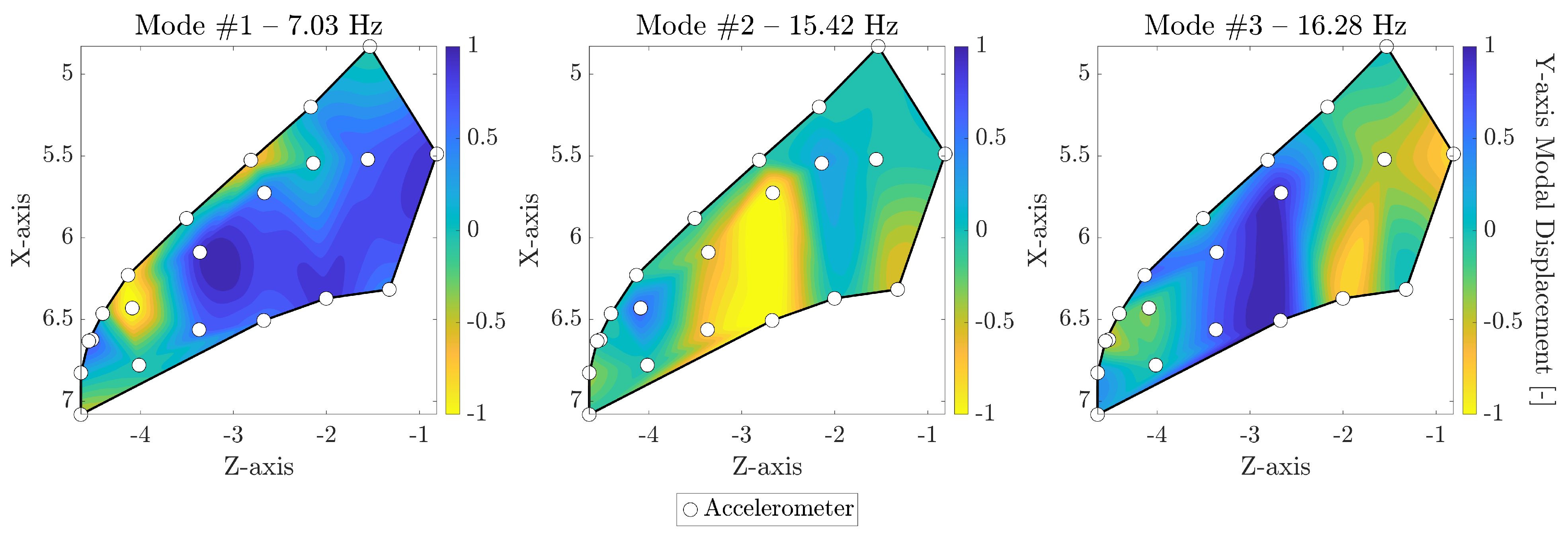
Notably, identification of the healthy case is extremely coherent with that of the literature case, which, however, is for a different excitation case. In addition, it is clear that it is impossible to directly use ω 1 3 and ζ 1 3 for SHM, as a clear trend within cases 1 to 3 cannot be identified. A further basis for comparison are ϕ n . These are addressed by computing the MAC of the corresponding mode. However, it is important first to visualise the given modes and recall their dominant displacement direction. ϕ n are shown in Figure 3.
In [14], mode #1 is the 1st bending (downwards) mode, mode #2 is the 2nd bending (downwards)mode and mode #3 is the 1st coupled mode between bending (downwards) and torsion.
After failing to carry out the SHM task using ω 1 3 and ζ 1 3 , it is useful to test whether the MAC provides clearer separation. A direct assessment of the damage state from the MAC (shown in Table 2) of the first three modes is not feasible: there is no strictly linear or monotonic relation between MAC and the damage cases.
In principle, the MAC between baseline and damaged mode shapes should decrease as damage increases, yet this does not happen uniformly across modes and cases. Accordingly, we compute the MTMAC complement, which jointly accounts for ω 1 3 and ϕ 1 3 , for cases 2–3 using case 1 (healthy state) as the baseline:
  • Case 2.  MTMAC = 0.158 ;
  • Case 3.  MTMAC = 0.175 .
As the MTMAC complement is used, larger values indicate greater deviation from the baseline and thus greater damage severity; the results therefore suggest case 3 is slightly more severe than case 2, which is the case since a heavier mass is used in case 3. This proves that the MTMAC is a viable single-value index for damage assessment.
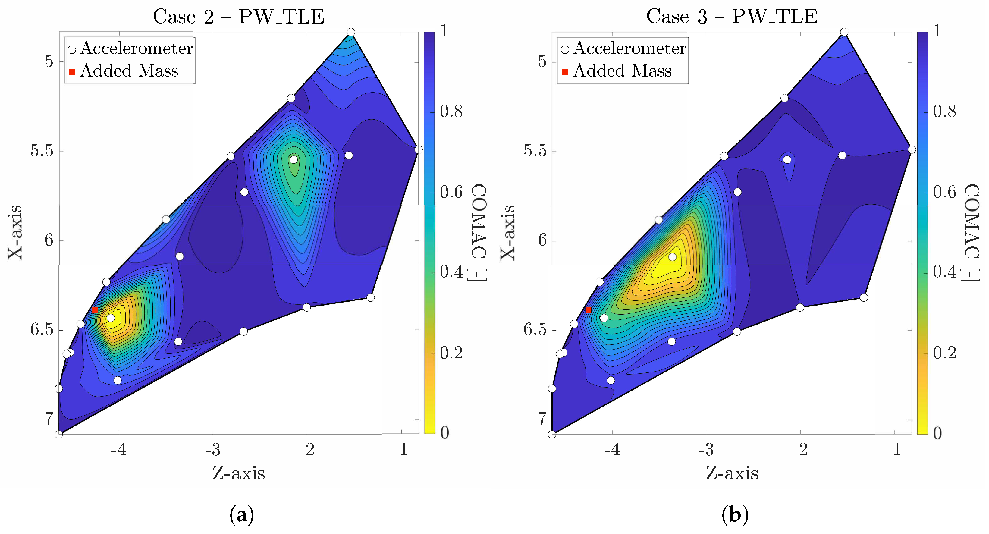
Now, for completeness, the damage is located using the scaled COMAC (between 0 and 1–0 is the highest relative ϕ n trajectory deviation) with ϕ 1 3 . These are shown in Figure 4.
In Figure 4, the most prominent areas where a deviation is observed in ϕ 1 3 are in the region near the tip of the wing, as well as close to the root section, around x 5. Notably, the maximum deviation for both cases is seen near the damaged area. However, when the mass is increased, the maximum deviation point shifts slightly towards the root (from z −4 m to −3.5 m).

4. Conclusions

In this work, a novel two-step vibration-based damage detection method is proposed and applied to the linear dynamics of a BAE Systems Hawk T1A aircraft port wing, resulting in the following findings:
  • The iLF has been experimentally proven to detect small damage-related changes in full-scale systems modal parameters, such as the BAE Systems Hawk T1A aircraft port wing;
  • The use of MTMAC as a damage assessment and quantification index has been validated;
  • Damage was successfully detected and localised in two cases of the recently introduced BAE Systems Hawk T1A aircraft MIMO dataset, using the proposed two-step method.
In conclusion, this study advocates for the future employment of the MTMAC as a damage index in aeronautical structures.
Opportunities for future work include the identification of the whole dataset (216 tests), carrying out damage detection on the whole set, and creating a finite element model of the airframe to carry out a statistical analysis to compare the identified results with a numerical model.

Author Contributions

Conceptualisation, G.D., and M.C.; methodology, G.D., and M.C.; software, G.D.; validation, G.D. and M.C.; formal analysis, G.D.; investigation, G.D. and M.C.; resources, G.D., M.C., A.M., B.C., and O.E.B.-M.; data curation, G.D. and M.C.; writing—original draft preparation, G.D.; writing—review and editing, G.D., M.C., A.M., B.C., and O.E.B.-M.; visualisation, G.D. and M.C.; project administration G.D. and M.C.; funding acquisition, G.D., M.C., A.M., B.C., and O.E.B.-M. All authors have read and agreed to the published version of the manuscript.

Funding

The authors from Universidad Carlos III de Madrid (UC3M) disclosed receipt of the following financial support for the research, authorship, and/or publication of this article: This work has been supported by the Madrid Government (Comunidad de Madrid, Spain) under the Multiannual Agreement with the UC3M (IA_aCTRl-CM-UC3M). The second and fourth authors are supported by the Centro Nazionale per la Mobilità Sostenibile (MOST—Sustainable Mobility Center), Spoke 7 (Cooperative Connected and Automated Mobility and Smart Infrastructures), Work Package 4 (Resilience of Networks, Structural Health Monitoring and Asset Management). The third author gladly acknowledges funding as a Beatriz Galindo Distinguished Senior Researcher by the Spanish Government.

Data Availability Statement

This study used third-party experimental data (BAE T1A Hawk Full Structure Modal Test) made available at [https://orda.shef.ac.uk/articles/dataset/BAE_T1A_Hawk_Full_Structure_Modal_Test/24948549 (accessed on 1 September 2024)] under a licence that the authors do not have permission to share.

Acknowledgments

The BAE T1A Hawk Full Structure Modal Test (https://orda.shef.ac.uk/articles/dataset/BAE_T1A_Hawk_Full_Structure_Modal_Test/24948549 (accessed on 1 September 2024)) dataset has been retrieved from the University of Sheffield data repository ORDA and is cited in this work. The authors thank the dataset authors and the LVV at the University of Sheffield for making them openly available.

Conflicts of Interest

The authors declare no conflicts of interest.

References

  1. Farrar, C.R.; Worden, K. An introduction to structural health monitoring. Philos. Trans. R. Soc. A Math. Phys. Eng. Sci. 2007, 365, 303–315. [Google Scholar] [CrossRef] [PubMed]
  2. Rytter, A.A. Vibrational Based inspection of Civil Engineering Structures. Ph.D. Thesis, Aalborg University, Aalborg, Denmark, 1993. [Google Scholar]
  3. Dessena, G.; Ignatyev, D.I.; Whidborne, J.F.; Pontillo, A.; Zanotti Fragonara, L. Ground vibration testing of a flexible wing: A benchmark and case study. Aerospace 2022, 9, 438. [Google Scholar] [CrossRef]
  4. Cawley, P. Structural health monitoring: Closing the gap between research and industrial deployment. Struct. Health Monit. 2018, 17, 1225–1244. [Google Scholar] [CrossRef]
  5. Pappa, R.S.; James, G.H.; Zimmerman, D.C. Autonomous Modal Identification of the Space Shuttle Tail Rudder. J. Spacecr. Rocket. 1998, 35, 163–169. [Google Scholar] [CrossRef] [PubMed]
  6. Dessena, G.; Civera, M.; Pontillo, A.; Ignatyev, D.I.; Whidborne, J.F.; Zanotti Fragonara, L. Noise-robust modal parameter identification and damage assessment for aero-structures. Aircr. Eng. Aerosp. Technol. 2024, 96, 27–36. [Google Scholar] [CrossRef]
  7. Dessena, G. Dataset: Structural Health Monitoring of a Flexible Wing. Zenodo 2024. [Google Scholar] [CrossRef]
  8. Wilson, J.; Champneys, M.D.; Tipuric, M.; Mills, R.; Wagg, D.J.; Rogers, T.J. Multiple-input, multiple-output modal testing of a Hawk T1A aircraft: A new full-scale dataset for structural health monitoring. Struct. Health Monit. 2024, 25, 1136–1149. [Google Scholar] [CrossRef]
  9. Wilson, J.; Champneys, M.D.; Tipuric, M.; Mills, R.; Wagg, D.J.; Rogers, T.J. BAE T1A Hawk Full Structure Modal Test. The University of Sheffield. 2024. Available online: https://orda.shef.ac.uk/articles/dataset/BAE_T1A_Hawk_Full_Structure_Modal_Test/24948549 (accessed on 1 September 2024).
  10. Perera, R.; Torres, R. Structural Damage Detection via Modal Data with Genetic Algorithms. J. Struct. Eng. 2006, 132, 1491–1501. [Google Scholar] [CrossRef]
  11. Lieven, N.A.J.; Ewins, D.J. Spatial Correlation of Mode Shapes, the Coordinate Modal Assurance Criterion (COMAC). In Proceedings of the 6th International Modal Analysis Conference, Kissimmee, FL, USA, 1–4 February 1988. [Google Scholar]
  12. Mayo, A.; Antoulas, A. A framework for the solution of the generalized realization problem. Linear Algebra Its Appl. 2007, 425, 634–662. [Google Scholar] [CrossRef]
  13. Dessena, G.; Civera, M.; Zanotti Fragonara, L.; Ignatyev, D.I.; Whidborne, J.F. A Loewner-Based System Identification and Structural Health Monitoring Approach for Mechanical Systems. Struct. Control Health Monit. 2023, 2023, 1891062. [Google Scholar] [CrossRef]
  14. Dessena, G.; Civera, M. Improved tangential interpolation-based multi-input multi-output modal analysis of a full aircraft. Eur. J. Mech.-A/Solids 2025, 110, 105495. [Google Scholar] [CrossRef]
  15. Allemang, R.J.; Brown, D.L. A correlation coefficient for modal vector analysis. In Proceedings of the 1st International Modal Analysis Conference, Schenectady, NY, USA, 8–10 November 1982; pp. 110–116. [Google Scholar]
  16. Dessena, G.; Civera, M.; Marcos, A.; Chiaia, B.; Bonilla-Manrique, O.E. Multiple input tangential interpolation-driven damage detection of a jet trainer aircraft. Aerosp. Sci. Technol. 2026, 168, 111032. [Google Scholar] [CrossRef]
Figure 1. BAE Systems Hawk T1A aircraft experimental setup at the LVV at the University of Sheffield. (a) shows the reference frame, its origin, and the shakers position, marked as (adapted from [8]), while (b) shows the simulated damage location on the port wing (adapted from [8]).
Engproc 133 00044 g001
Figure 2. Sensors position (X) on the BAE Systems Hawk T1A aircraft port wing. points to the port wing shaker position (adapted from [8]).
Engproc 133 00044 g002
Figure 3. BAE Systems Hawk T1A aircraft case 1 ϕ 1 3 (retrieved from [16]).
Engproc 133 00044 g003
Figure 4. Scaled COMAC for the BAE Systems Hawk T1A aircraft port wing identified via iLF from cases (a) 2, and (b) 3 (adapted from [16]).
Engproc 133 00044 g004
Table 1. BAE Systems Hawk T1A aircraft ω 1 3 and ζ 1 3 identified from cases 1 to 3 alongside the literature results, coming from a test at lower amplitude.
Mode #Natural Frequency [Hz]-(Difference [%])Damping Ratio [-]-(Difference [%])
0.4 V Input [14]Case 1Case 2 Case 3 0.4 V Input [14]Case 1Case 2Case 3
16.987.036.956.880.030.030.020.02
(0.7)(−1.14)(−2.13) (0)(−33.33)(−33.33)
215.4315.4215.5315.430.010.010.010.01
(−0.1)(0.71)(0.06) (0)(0)(0)
316.3216.2816.2416.250.010.010.010.01
(−0.3)(−0.25)(−0.18) (0)(0)(0)
Table 2. MAC matrices diagonal values between cases 2–3 and the healthy state of the BAE Systems Hawk T1A aircraft.
Case23
Model #
10.900.85
20.961.00
30.990.98
Disclaimer/Publisher’s Note: The statements, opinions and data contained in all publications are solely those of the individual author(s) and contributor(s) and not of MDPI and/or the editor(s). MDPI and/or the editor(s) disclaim responsibility for any injury to people or property resulting from any ideas, methods, instructions or products referred to in the content.