Proceeding Paper

Structural Assessment of a Compact Offset Strip Fin Heat Exchanger for Hydrogen Fuel Cell Electric Aircraft †
German Aerospace Center (DLR e.V.), Institute of Electrified Aero Engines, Lieberoser Str. 13A, 03046 Cottbus, Germany
*
Author to whom correspondence should be addressed.
Presented at the 15th EASN International Conference, Madrid, Spain, 14–17 October 2025.
Eng. Proc. 2026, 133(1), 195; https://doi.org/10.3390/engproc2026133195
Published: 10 June 2026

Abstract

Hydrogen fuel cells offer strong potential for decarbonizing aviation, yet their megawatt-scale integration is limited by thermal management system (TMS) challenges. In low-temperature Proton Exchange Membrane Fuel Cell (PEMFC) systems, the heat exchanger (HEX) is the key TMS component influencing thermal efficiency, mass, and reliability. While prior work has focused on thermo-hydraulic optimization, structural behavior under flight conditions remains insufficiently addressed. This study introduces a coupled CFD–FEA methodology for a nacelle-integrated, megawatt-class plate–fin HEX. The model captures the effects of non-uniform thermal loads, constrained thermal expansion, and dynamic excitation. Local flow-induced vibrations are assessed through pre-stressed modal analysis, and global dynamic behavior is predicted using a homogenized approach. Results show that thermally induced stresses dominate over pressure loads, and the introduction of coolant-fin geometries with suitable expansion tolerances mitigates stress and resonance risks. The approach provides design guidance for structurally robust, vibration-tolerant, and aero-thermally efficient HEXs for next-generation PEMFC-powered aircraft.

1. Introduction

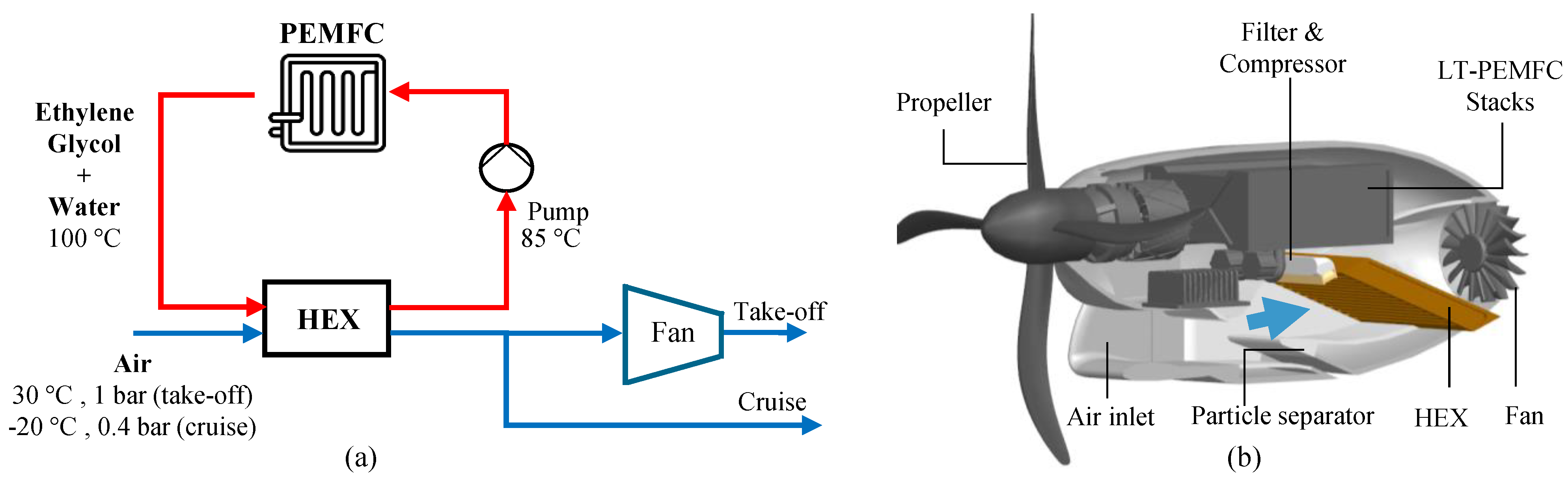
Hydrogen-powered Proton Exchange Membrane Fuel Cells (PEMFCs) are considered a key technology for enabling climate-neutral regional aviation by 2050 [1,2]. However, scaling low-temperature PEMFC propulsion systems to the megawatt class imposes demanding thermal-management systems (TMS) requirements due to low stack operating temperatures and large heat rejection rates. Within the TMS, the heat exchanger (HEX) is the primary component governing thermal efficiency, system mass, integration volume, and reliability [3] as illustrated in Figure 1a. Among available designs, the plate-fin HEX with offset strip fins offers superior aero-thermal performance, compactness, and reliability for electric aviation [4,5].
While substantial research has focused on HEX designs and thermo-hydraulic optimization [6], the structural assessment of aviation grade plate–fin HEXs under realistic flight conditions remains insufficiently explored. Existing studies typically consider simplified thermal fields, uniform temperatures, welded-fin configurations, or free expansion assumptions [7,8,9]. Consequently, the coupled influence of (i) non-uniform CFD-derived temperature and pressure fields, (ii) constrained thermal expansion due to nacelle integration, and (iii) dynamic excitations from airflow and rotating machinery has not been systematically quantified. This study addresses these gaps by performing a comprehensive structural and modal assessment of a nacelle-integrated, 1 MW offset-strip plate–fin HEX for a PEMFC-powered ATR-42 aircraft (Figure 1b). A coupled CFD–FEA methodology is used to map non-uniform thermal and pressure loads onto the structural domain, evaluate thermo-elastic stresses, and assess the impact of mechanical constraints associated with nacelle integration. Local flow-induced vibrations (FIV) are analyzed using pre-stressed modal analysis, while global vibration behavior is captured using a homogenized material model. The objective is to maintain elastic behavior with a safety factor ≥ 1.5 and ensure natural frequencies remain well separated from aerodynamic and mechanical excitations. The findings provide design guidelines for structurally robust, vibration-tolerant HEXs suitable for future megawatt-class hydrogen-electric propulsion systems.

2. Design Methodology

2.1. Reliability and Failure of HEX for Aviation

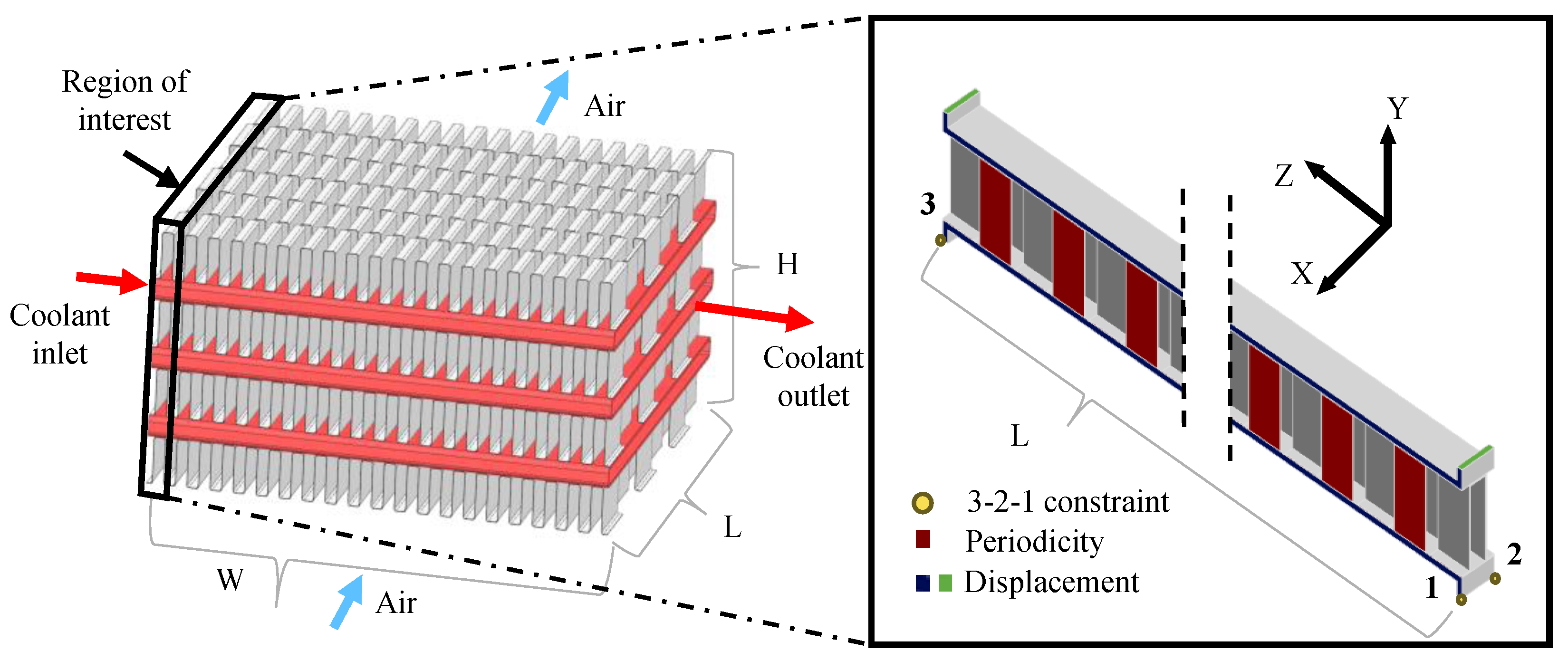
For the PEMFC-powered ATR-42 regional aircraft (70 passengers, 1200 km range, Mach 0.5 at 7315 m), the TMS must dissipate nearly 1 MW of heat during take-off and about 0.68 MW in cruise. The TMS layout, shown in Figure 1a, directly governs the HEX design requirements. A ducted cross-flow HEX is integrated within the nacelle, employing Kays & London offset-strip fins (1/8–15.61) [10] on the air-side and 2 mm-high rectangular coolant channels as the baseline configuration (Figure 2). The coolant circuit operates as a closed loop, whereas the air-side is exposed to variable temperature and pressure conditions representative of flight operation. HEX sizing was conducted using a unit-cell CFD approach combined with the core mass–velocity method [5]. Conjugate heat-transfer simulations provided detailed temperature and pressure fields for both take-off and cruise conditions (see Figure A1 and Figure A2), which were subsequently mapped to the structural model. Aluminium 3003-H18 was selected as the material owing to its low density and yield strength of 145 MPa (Table A1) [11]. Among potential degradation mechanisms such as corrosion, fouling, leakage, and foreign-object damage, fatigue is identified as the primary failure mode [12]. It is driven by cyclic thermal and pressure loading, constrained thermal expansion, and vibrations induced by propeller and fan pulsations.

2.2. Structural Analysis Setup

Structural analysis was performed on a representative air-side unit cell of the HEX to capture the thermo-elastic response under combined pressure and thermal loading. The selected region as shown in Figure 2 corresponds to the zone of maximum air–coolant temperature difference. A Cartesian system was defined with X along the coolant flow, Y along the stack height, and Z along the air-flow direction. To eliminate rigid body motion, a 3-2-1 constraint was applied to three non-collinear vertices [13]. A mesh convergence study confirmed accuracy (Figure A3), and the final mesh of 139 k elements (Table A2) satisfied all quality criteria. Periodic boundaries were imposed on bisected fin surfaces to ensure geometric continuity between adjacent cells. Displacement constraints were applied to represent duct-induced restrictions for free and rigid constraints. For free expansion, periodic conditions were extended to all lateral faces to prevent strain discontinuities. Structural integrity was assessed using the von Mises stress criterion.

2.3. Modal Analysis Setup

The ducted HEX is subjected to various dynamic excitations arising from aerodynamic and mechanical sources. Among these, two dominant types are analyzed in this study: (i) flow-induced vibrations (FIV) generated by airflow through the fin passages [14], and (ii) HEX-stack vibrations driven by pulsating air flow originating from rotating machinery. During take-off, high inlet velocities promote early flow separation as the fins behave as bluff bodies, producing alternating vortex shedding and an unsteady pressure field that induces oscillating lift forces. These fluctuating aerodynamic loads excite local fin vibrations characteristic of FIV [15]. The vortex-shedding frequency f s is estimated using the Strouhal number S t (typically 0.2–0.4 for bluff bodies):
f s = S t · u D h ,
where u is the characteristic flow velocity, and D h the hydraulic diameter. A pre-stressed modal analysis is then performed to determine the natural frequencies under operational stress conditions and assess resonance risks with vortex-shedding frequency. The influence of thermal-expansion tolerances on the natural frequencies is also evaluated to ensure adequate frequency separation.
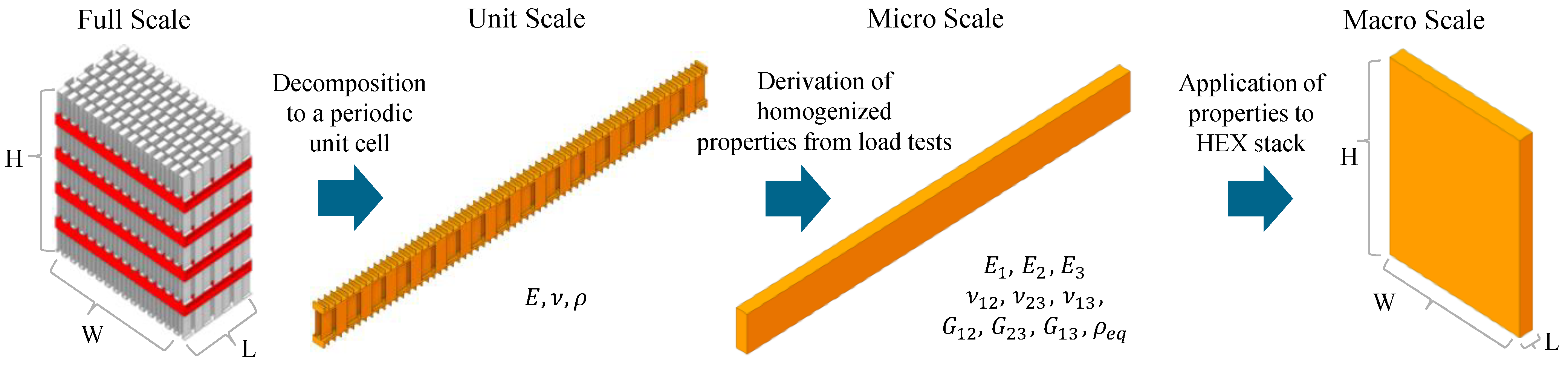
In addition to local fin excitation, global dynamic loading arises from pulsating airflow produced by the propeller and TMS fan, operating at 1800 RPM (30 Hz) and 6000 RPM (100 Hz), respectively. To capture this behavior efficiently, the geometrically complex HEX is homogenized into a contiguous solid (Figure 3), with equivalent properties obtained from a representative volume element (RVE) of the unit-cell geometry [12]. The unit cell in this study comprises a periodic arrangement of fins and separating plates that introduces three mutually orthogonal symmetry planes. These symmetry planes eliminate all shear–normal and shear–shear coupling terms in the compliance tensor, leaving only the direct normal and direct shear components. A material with this symmetry class is orthotropic and is fully described by three Young’s moduli E i , three shear moduli G i j , and three Poisson’s ratios ν i j . The effective properties were obtained using ANSYS (version 2024 R1) Material Designer [16], which applies six finite-element load cases to compute the homogenized stiffness and compliance tensors. The resulting equivalent elastic constants, together with the effective density ρ e q and coefficient of thermal expansion α , are summarized in Table A3. These values were validated against a 5 × 5 explicit unit-cell model, showing deviations below 5% (Table A4), and are subsequently used in the global modal analysis of the HEX.

3. Results and Discussion

3.1. Structural Analysis

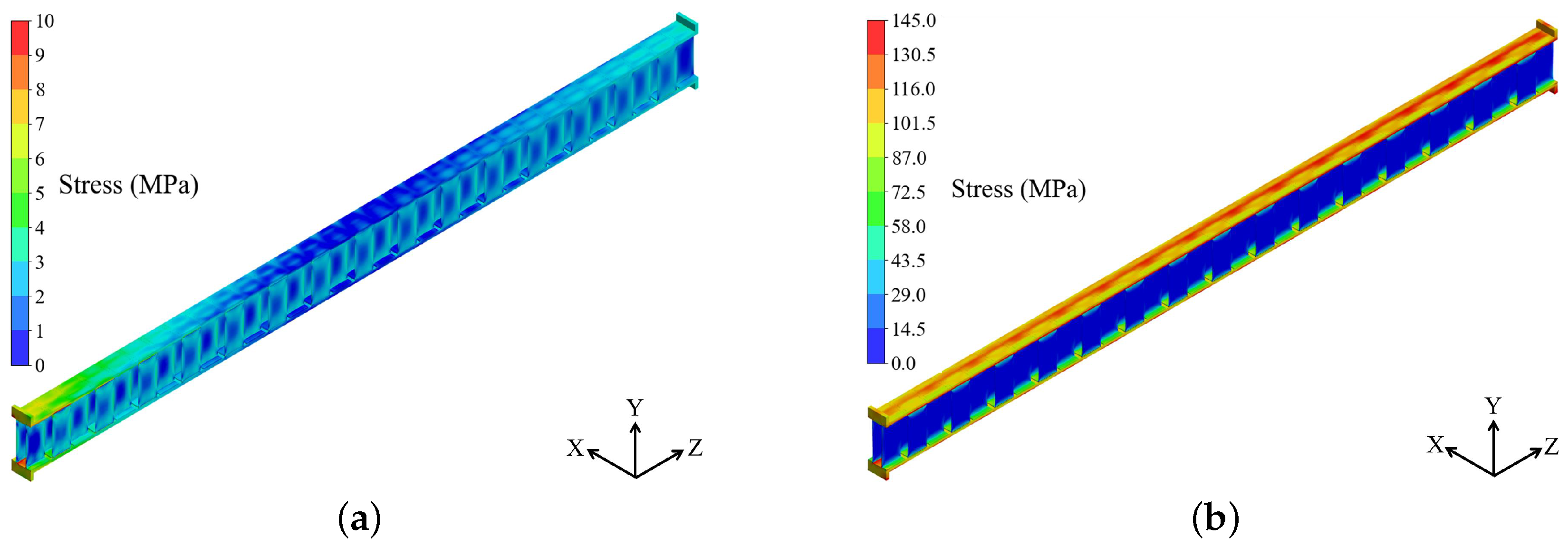
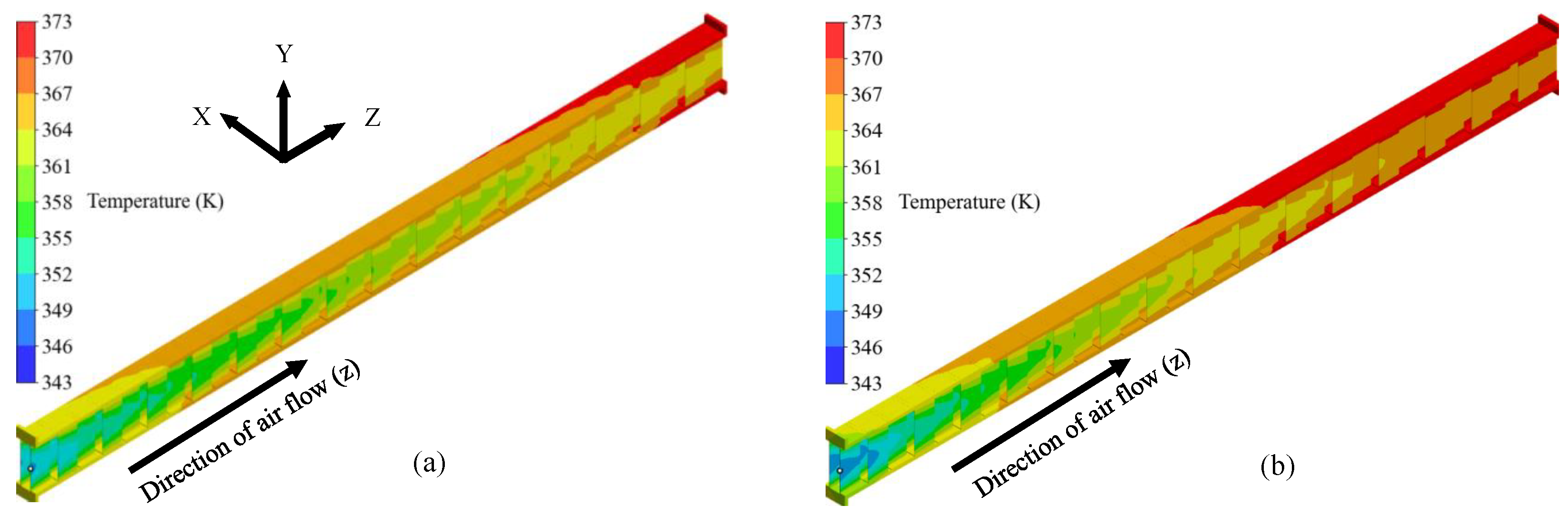
The HEX structure was first evaluated under free thermal expansion in all directions. As shown in Figure 4a, the maximum fin stresses ranged between 3 and 4 MPa, primarily governed by pressure loads. The thermal expansions for the baseline configuration are summarized in Table 1. At take-off, the HEX rejects more total heat to warmer, denser air, whereas at cruise the lower heat duty is offset by higher local heat fluxes to the colder ambient, resulting in similar temperature profiles across both operating points. These similar profiles (Figure A1) lead to comparable thermal-expansion behavior; therefore, subsequent analyses focus on the take-off case. For the duct-integrated HEX, the structural response was then examined under thermal-expansion constraints. Z-axis constraints had negligible effect, while X–Y restrictions significantly altered the stress field. Under X-axis constraint (Figure 4b), thermal stresses became dominant, raising local stresses close to the yield strength and inducing localized plasticity. Such deformation degrades fatigue life, consistent with the observations of Carter [8]. The elevated stress levels primarily result from the large aspect ratio on the coolant side. To mitigate these effects, additional coolant-side fins were incorporated, redistributing stresses more uniformly across the fins.

3.1.1. Inclusion of Coolant Fins

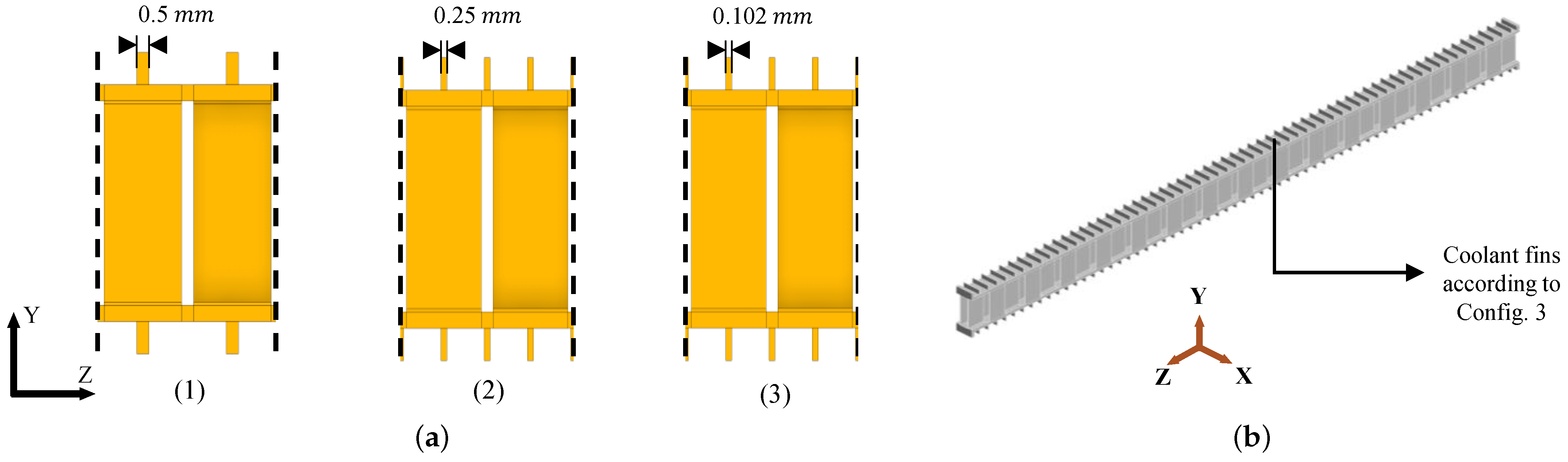
Figure 5a illustrates three coolant-fin configurations aligned with the air-side fin centers: configuration (1): 0.5 mm thick; configuration (2): 0.25 mm thick, positioned over the air-side fin spacing; and configuration (3): 0.102 mm fins, matching both the air-side fin thickness and spacing. All configurations were analyzed under rigid constraints in Y direction, with stress distributions evaluated along normalized paths on an intermediate air-side fin (Figure A4a). The fins comparisons were compared based on flow area reduction, contact area increase and peak stress reduction compared to the baseline case of no coolant fins. Configurations 1 and 2 resulted in 13% and 14% flow area reduction, respectively, while configuration 3 minimized this to 5.6%. Compared to configuration 1 (38%), the contact area increased by 93% for configuration 2 and by 101% for configuration 3. In terms of mechanical response, configuration 3 achieved a 39% reduction in peak stress compared to the baseline, whereas configurations 1 and 2 achieved 8% and 28% reductions, respectively. Considering both thermo-fluid and structural metrics, configuration 3 is identified as the best design out of the three presented configurations. The modified unit cell with configuration 3 (Figure 5b) was sized for a 1 MW duty while maintaining a constant air-side length. Compared to the initial HEX stack (Table 1), the redesigned geometry exhibits a greater stack height and reduced coolant-flow width due to enhanced heat transfer. The narrower width mitigates X-axis thermal expansion and lowers plate stresses, while the increased height supports modular integration and staggered coolant distribution across multiple nacelles. Key performance indicators—gravimetric and volumetric power density, power ratio (heat duty/pumping power), and frontal area—were used for comparison [5]. As summarized in Table 1, the modified concept increases gravimetric power density by 16.6%, volumetric by 59.2%, and reduces frontal area by 14.5%, thereby lowering aerodynamic drag. Although pressure drops on both sides increase slightly, the effect on power ratio is minor. Overall, the redesigned HEX offers enhanced thermal performance, lower structural stress, and improved integration compared to the baseline case.

3.1.2. Inclusion of Expansion Tolerance

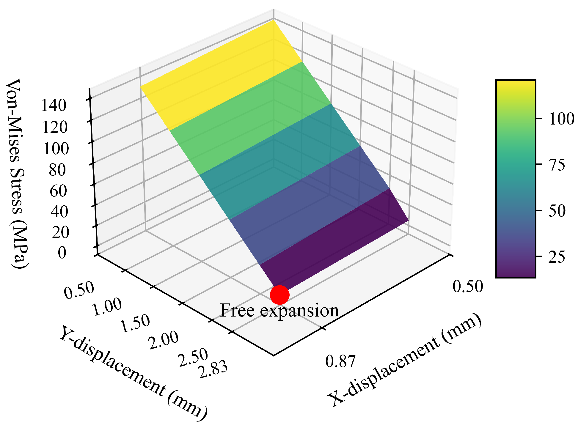
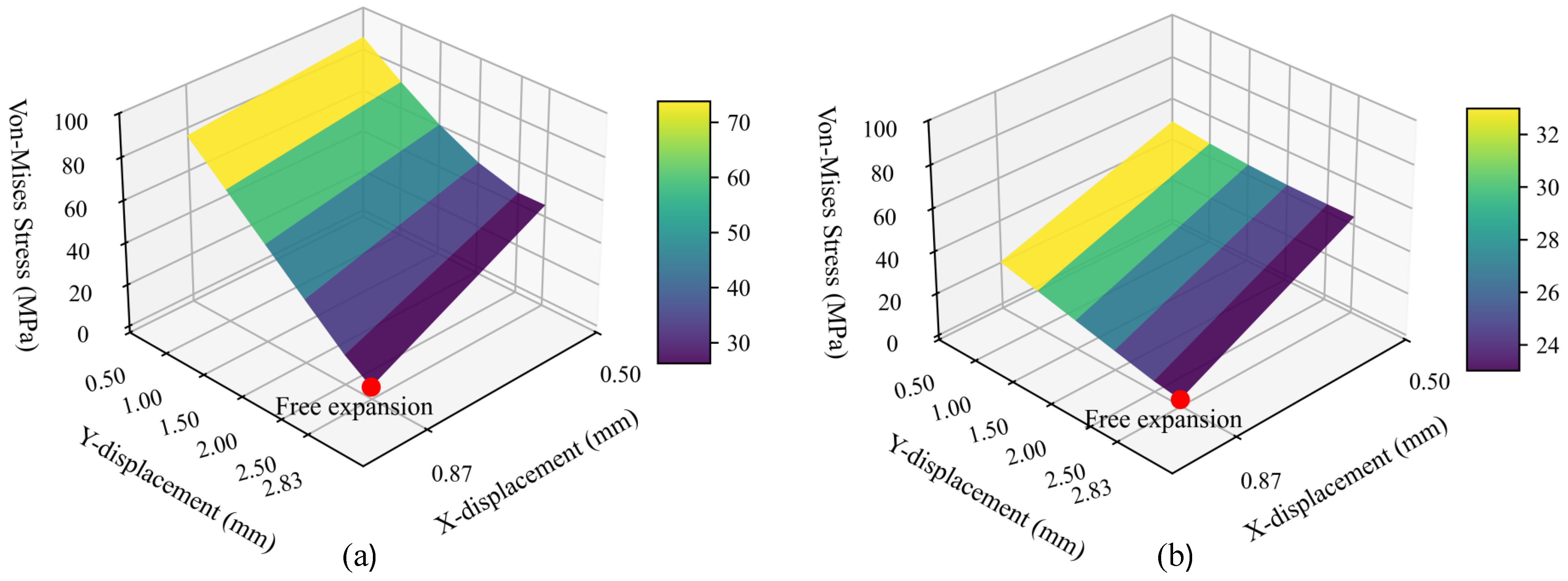
Thermal-expansion tolerances are essential to mitigate structural stresses in the HEX. As indicated in Table 1, provisions are required along the X and Y axes, while expansion along the Z-axis remains negligible. Displacement conditions were applied in X with magnitude of 0.5–0.872 mm (free expansion) and Y with 0.5–2.83 mm (free expansion). Air-side fins exhibited the highest stress sensitivity, whereas coolant fins and separating plates experience lower stresses (see Figure A5). Figure 6 shows the air-side stress distributions for different tolerance configurations. Constraining thermal expansion along the X and Y axes leads to substantially higher stresses, approaching the material yield limit, whereas free-expansion conditions keep stresses below 10 MPa. The response is more sensitive to Y-axis restriction due to the higher aspect ratio of fin height relative to pitch in the 1/8–15.61 fin geometry. For safety considerations, configurations with tolerances of 0.5 and 1 mm for X and Y displacement were excluded, as they yield factors of safety below 1.5.

3.2. Modal Analysis

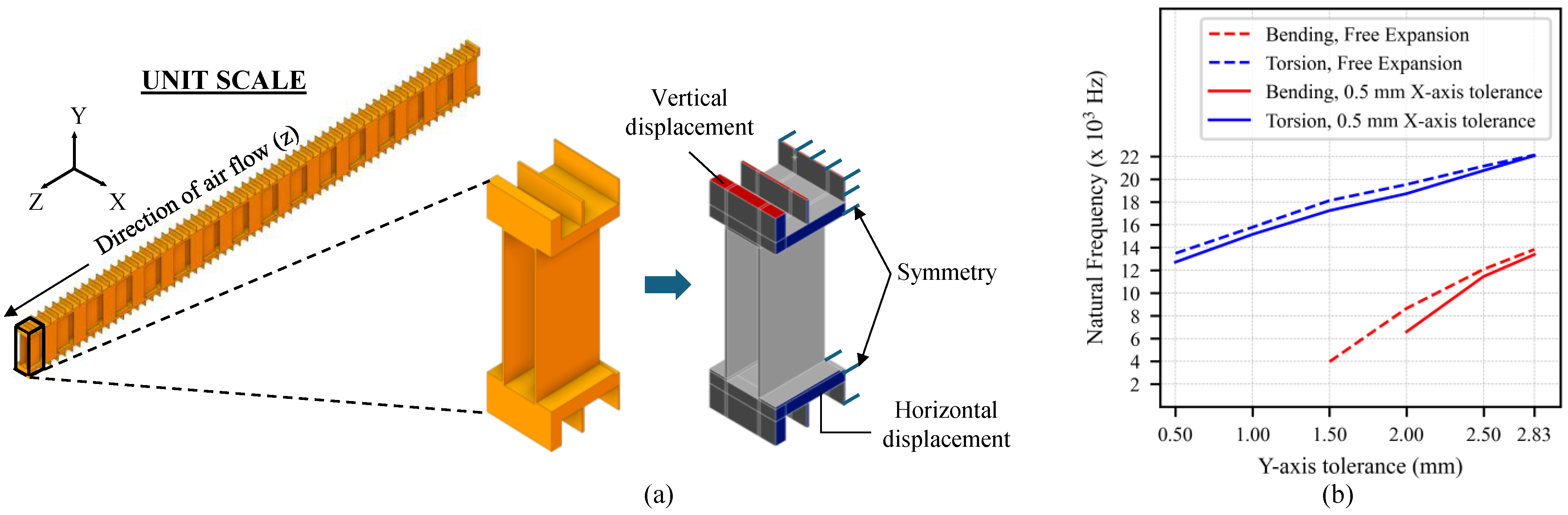
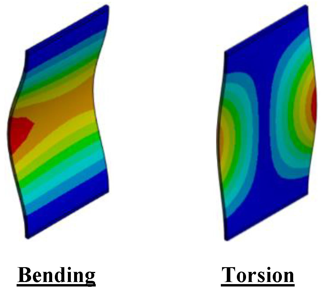
The last fin in the air-flow direction of the modified unit cell (Figure 7a) was selected for the pre-stressed modal analysis, as outlet velocities on the air-side are higher than at the inlet due to heat transfer from the coolant. The mesh, boundary conditions, and CFD-derived pressure and temperature fields at take-off conditions were applied consistently with the unit-cell CFD model. Symmetry and displacement boundary conditions in the X- and Y-axes were imposed to represent thermal-expansion tolerances. The resulting natural frequencies are shown in Figure 7b, with bending and torsional modes identified (see Figure A6). Increasing the Y-axis tolerance reduces compressive thermal stresses in the fin, which increases the effective stiffness through stress-stiffening in the pre-stressed eigenvalue problem and therefore raises the natural frequencies. The vortex-shedding frequency at a take-off air velocity of 20 m/s was estimated as 2800 Hz using Equation (1). For the configuration with free expansion of X and Y = 1.5 mm, the natural frequency of 3960 Hz lies close to the shedding frequency and within a safety factor of 1.5, indicating a potential resonance risk. All other configurations remain well separated from the shedding frequency and are therefore considered structurally safe.
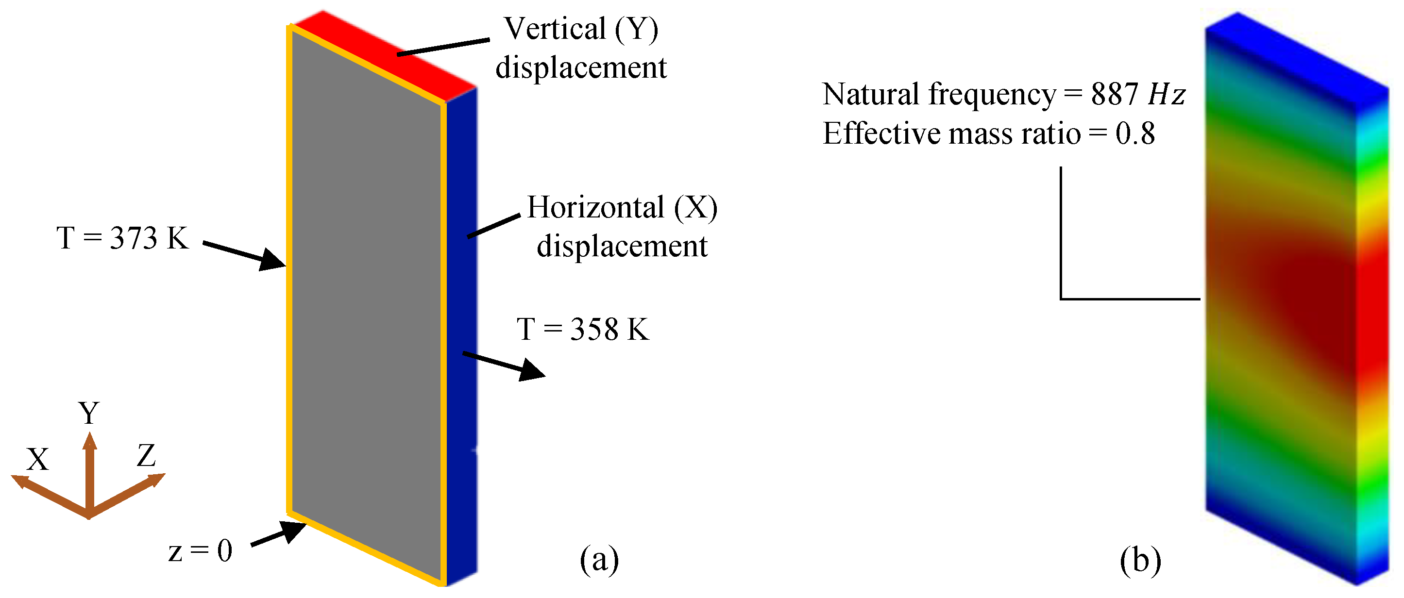
The boundary conditions for the global vibration analysis of the HEX stack are shown in Figure 8a. A linear temperature gradient (373–358 K) and displacement boundary conditions were applied, while the frontal edges were fixed in the Z-direction to suppress rigid body motion. The resulting global mode shape and natural frequency are presented in Figure 8b. For the analyzed configuration, the first natural frequency is 887 Hz, with approximately 80% of the structural mass participating in the mode. Similar frequencies (887–888 Hz) were obtained for all remaining X- and Y-axis tolerance cases, indicating that the expansion tolerance has minimal influence on the global dynamic response. The dominant global frequency is substantially higher than the excitation frequencies of the propeller and TMS fan, ensuring adequate separation from resonance under all examined conditions. A summary of the structural assessment across all tolerance configurations is provided in Table 2. Four configurations exceed acceptable stress limits and are marked in red, while one configuration (blue) indicates a potential resonance risk associated with FIV. The remaining seven configurations meet both the elastic stress limits and the required separation from excitation frequencies, fulfilling the structural criteria defined for this study. These findings provide a solid basis for selecting suitable mounting and fixation strategies for the HEX under combined thermal and dynamic loading.

4. Conclusions and Outlook

A preliminary structural and modal analysis of a megawatt-class offset-strip plate–fin HEX was conducted for nacelle-integrated PEMFC propulsion. The coupled CFD–FEA analysis demonstrated that thermally induced stresses—primarily arising from constrained thermal expansion—dominate over pressure loads. Incorporating coolant-side fins and introducing thermal-expansion tolerances effectively mitigated stress while improving weight efficiency, compactness, and thermo-mechanical robustness. The FIV analysis demonstrated that appropriate expansion tolerances maintain adequate separation between the vortex-shedding and natural frequencies, preventing resonance under operational air velocities. A homogenized modal approach accurately captures the global vibration behavior of the HEX stack, enabling efficient evaluation of system-level dynamics without resolving individual fins. Overall, the findings provide clear structural design guidance for plate–fin HEXs operating under combined thermal, aerodynamic, and mechanical constraints in future megawatt-class PEMFC propulsion systems. Future work will focus on shape optimization for further stress reduction, integration of a multidisciplinary HEX design framework, and experimental validation of the structural and dynamic behavior.

Author Contributions

This work is based on the master’s thesis of S.P., who performed the structural and modal analyses. S.B. supervised the study, carried out CFD simulations for take-off and cruise, and led manuscript preparation. M.K. and S.K. provided guidance on structural evaluation and TMS integration. All authors have read and agreed to the published version of the manuscript.

Funding

This work contributes to the internal DLR project HEADS.

Institutional Review Board Statement

Not applicable.

Informed Consent Statement

Not applicable.

Data Availability Statement

Not applicable

Conflicts of Interest

The authors declare no conflicts of interest.

Appendix A. Structural & Modal Analysis

Appendix A.1. Material Properties

Table A1. Thermal and mechanical properties of Aluminium 3003 H-18 at 373 K [11].
Material StrengthMagnitude
Young’s Modulus (E)69 GPa
Poisson’s ratio ( ν )0.33
Ultimate Tensile Strength ( σ u t )180 MPa
Yield Strength ( σ y )145 MPa
Density ( ρ )2730 kg/m3
Thermal-Expansion Coefficient ( α )2.32 × 10 5 1/K
Thermal Conductivity ( κ )160 W/mK

Appendix A.2. Temperature and Pressure Boundary Conditions

Figure A1. Temperature distribution of the unit cell under take-off (a) and cruise (b) conditions.
Engproc 133 00195 g0a1
Figure A2. Pressure boundary conditions applied to the unit cell under take-off (a) and cruise (b) conditions.
Engproc 133 00195 g0a2

Appendix A.3. Finite Element Mesh and Convergence Study
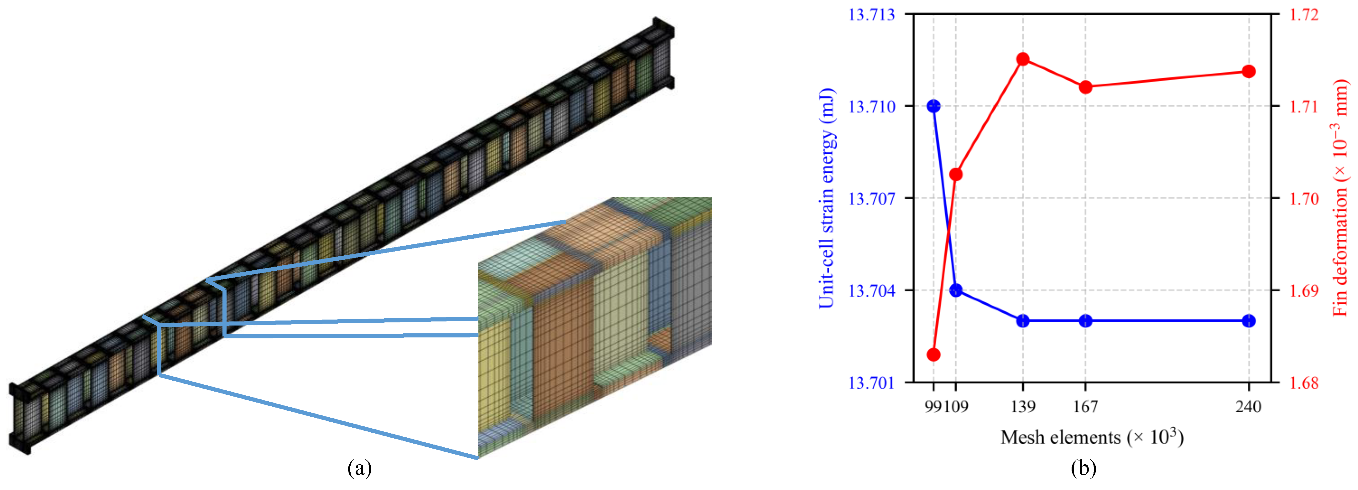
Figure A3. Meshing: Hexahedral mesh of the unit cell (a) and mesh independence study (b).
Engproc 133 00195 g0a3
Table A2. Mesh quality metrics.
MetricMeanStd. Dev.Remarks
Skewness0.0620.123Range: 0 (ideal)–1 (failed mesh)
Aspect Ratio2.6011.89Within 1 (ideal)–5 as best practice
Jacobian Ratio0.9730.053Within 1 (ideal)–5 as best practice

Appendix A.4. Structural Analysis: Rigid Constraints
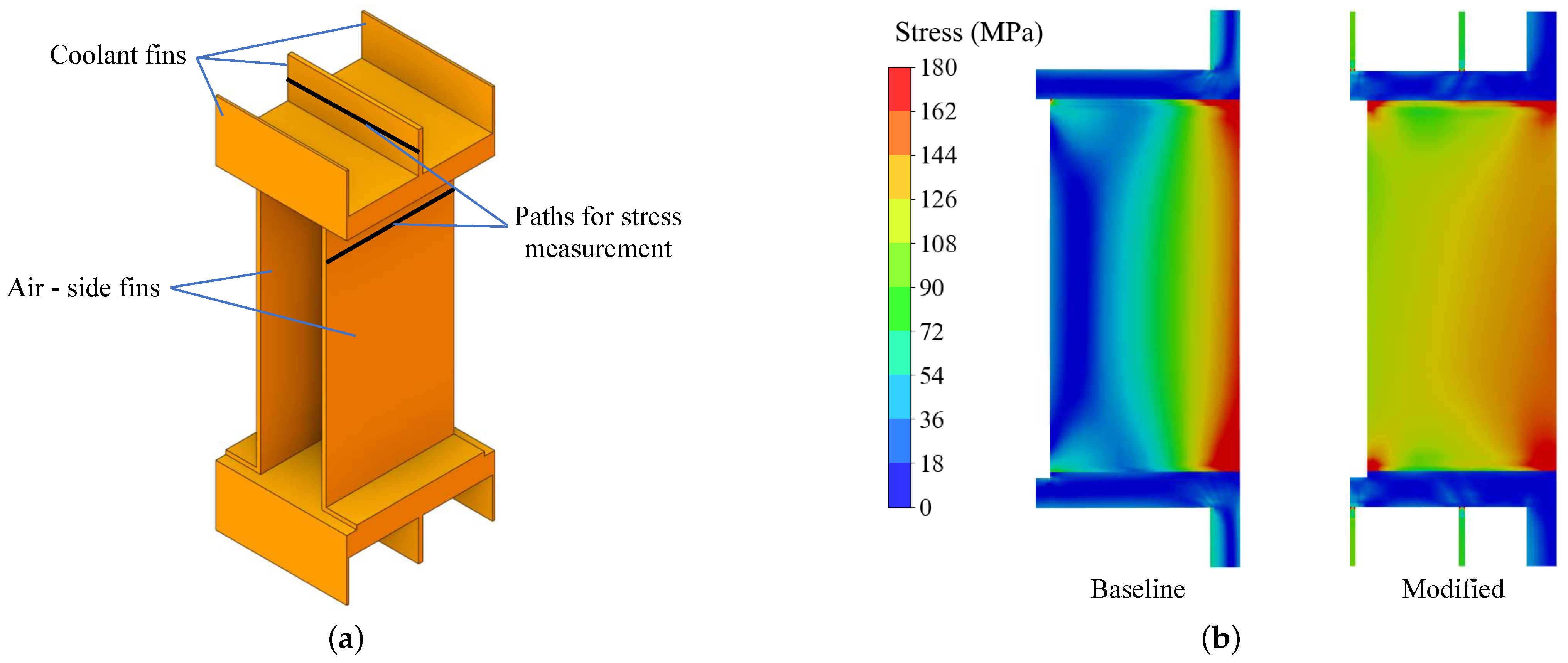
Figure A4. Constraint along vertical Y direction: Paths of stress measurement (a) and comparison of stress distribution in the last air-side fin between the baseline and modified HEX configurations (b).
Engproc 133 00195 g0a4
Figure A5. Peak stress distribution for various tolerances: coolant fins (a) and separating plates (b).
Engproc 133 00195 g0a5

Appendix A.5. Modal Analysis: Flow-Induced Vibration

Figure A6. Mode shapes obtained for flow-induced vibration. The color scale represents the relative normalized modal displacement magnitude, where blue denotes lower deformation and red denotes higher deformation.
Engproc 133 00195 g0a6

Appendix A.6. Homogenized Model Material Properties and Validation

Table A3. Thermo-elastic properties of the homogenized unit cell. Material axes 1–2–3 correspond to the X, Y and Z directions, respectively.
Material ConstantValueMaterial ConstantValue
E 1 8.81 GPa ν 12 0.0942
E 2 4.08 GPa ν 23 0.030
E 3 8.29 GPa ν 13 0.314
G 12 1.65 MPa α 1 2.32 × 10 5 1/K
G 23 85.99 MPa α 2 2.32 × 10 5 1/K
G 13 2.99 GPa α 3 2.32 × 10 5 1/K
ρ e q 454.33 kg/m3
Table A4. Comparison between the deformations of the homogenized model and the 5×5 explicit unit-cell model.
Load CaseMajor Deformation DirectionOriginal (mm)Homogenized (mm)Error (%)
Tension along X-axisX 3.25 × 10 5 3.25 × 10 5 0.09
Tension along Y-axisY 6.01 × 10 4 6.12 × 10 4 1.78
Tension along Z-axisZ 1.77 × 10 3 1.76 × 10 3 0.49
Shear along XY planeX 1.54 1.56 1.53
Shear along YZ planeZ 2.77 × 10 2 2.99 × 10 2 8.34
Shear along XZ planeZ 1.06 × 10 4 1.09 × 10 4 3.18

References

  1. European Commission. Clean Sky 2 First Global Assessment 2020: Technology Evaluator Report. 2021. Available online: https://cleansky.paddlecms.net/sites/default/files/2021-10/TE-FGA-TR_en.pdf (accessed on 30 July 2025).
  2. Kazula, S.; De Graaf, S.; Enghardt, L. Review of fuel cell technologies and evaluation of their potential and challenges for electrified propulsion systems in commercial aviation. J. Glob. Power Propuls. Soc. 2023, 7, 43–57. [Google Scholar] [CrossRef] [Scilit]
  3. Sain, C.K.; Hänsel, J.; Kazula, S. Conceptual design of air and thermal management in a nacelle-integrated fuel cell system for an electric regional aircraft. In Proceedings of the AIAA AVIATION 2023 Forum, San Diego, CA, USA, 12–16 June 2023. [Google Scholar] [CrossRef] [Scilit]
  4. Bhapkar, S.; Sain, C.; Kazula, S. Review and evaluation of hydrogen and air heat exchangers for fuel cell-powered electric aircraft propulsion. Eng. Proc. 2025, 90, 62. [Google Scholar] [CrossRef] [Scilit]
  5. Bhapkar, S.; Sain, C.; Kazula, S. Design of heat exchangers with cooling fins in fuel cell-powered electric aircraft: Genetic optimization approach with CFD validation. In Proceedings of the 2025 IEEE/AIAA Transportation Electrification Conference and Electric Aircraft Technologies Symposium (ITEC+EATS), Anaheim, CA, USA, 18–20 June 2025. [Google Scholar] [CrossRef] [Scilit]
  6. Qasem, N.A.; Zubair, S.M. Compact and microchannel heat exchangers: A comprehensive review of air-side friction factor and heat transfer correlations. Energy Convers. Manag. 2018, 173, 555–601. [Google Scholar] [CrossRef] [Scilit]
  7. Rajesh, S.; Bang, H.S.; Chang, W.S.; Kim, H.J.; Bang, H.S.; Oh, C.I.; Chu, J.S. Numerical determination of residual stress in friction stir weld using 3D-analytical model of stir zone. J. Mater. Process. Technol. 2007, 187–188, 224–226. [Google Scholar] [CrossRef] [Scilit]
  8. Carter, P.; Carter, T.; Viljoen, A. Failure analysis and life prediction of a large, complex plate-fin heat exchanger. Eng. Fail. Anal. 1996, 3, 29–43. [Google Scholar] [CrossRef] [Scilit]
  9. Ma, H.; Hou, C.; Yang, R.; Li, C.; Ma, B.; Ren, J.; Liu, Y. The influence of structure parameters on stress of plate-fin structures in LNG heat exchanger. J. Nat. Gas Sci. Eng. 2016, 34, 85–99. [Google Scholar] [CrossRef] [Scilit]
  10. Shah, R.K.; Sekulić, D.P. Fundamentals of Heat Exchanger Design; John Wiley & Sons: Hoboken, NJ, USA, 2003. [Google Scholar]
  11. Davis, J.R. Aluminum and Aluminum Alloys; ASM International: Almere, The Netherlands, 1993. [Google Scholar]
  12. Ge, L.; Jiang, W.; Wang, Y.; Tu, S.T. Creep-fatigue strength design of plate-fin heat exchanger by a homogeneous method. Int. J. Mech. Sci. 2018, 146, 221–233. [Google Scholar] [CrossRef] [Scilit]
  13. Tips & Tricks: 3-2-1 Jig Theory Applied to FEA Boundary Conditions. Available online: https://www.motovated.co.nz/tips-tricks-3-2-1-jig-theory-applied-fea-boundary-conditions/ (accessed on 17 July 2025).
  14. Goyder, H. Flow-induced vibration in heat exchangers. Chem. Eng. Res. Des. 2002, 80, 226–232. [Google Scholar] [CrossRef] [Scilit]
  15. Matsumoto, M. Vortex shedding of bluff bodies. J. Fluids Struct. 1999, 13, 791–811. [Google Scholar] [CrossRef] [Scilit]
  16. ANSYS Inc. Ansys Material Designer, Ansys 2024 R1; ANSYS Inc.: Canonsburg, PA, USA, 2024.
Figure 1. Schematic of the PEMFC TMS showing the coolant loop and air channel. Red lines indicate the ethylene glycol–water coolant loop, while blue lines indicate the air flow path through the HEX and fan (a) and HEX integrated in nacelle [3] (b).
Engproc 133 00195 g001
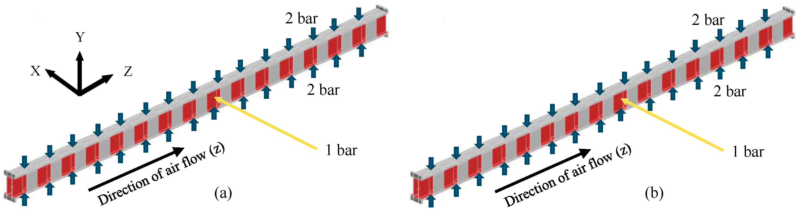
Figure 2. HEX geometry showing coolant channels (red) and air channels (blue) in cross-flow, along with the applied boundary conditions for the baseline unit-cell configuration.
Engproc 133 00195 g002
Figure 3. Homogenization procedure.
Engproc 133 00195 g003
Figure 4. Stress distribution for free expansion (a) and constraint along X-axis (b).
Engproc 133 00195 g004
Figure 5. Coolant-fin configurations investigated (a) and modified unit cell case (b).
Engproc 133 00195 g005
Figure 6. Air-side von Mises peak stress distribution for different thermal-expansion tolerances.
Engproc 133 00195 g006
Figure 7. Last fin for flow-induced vibration analysis (a) and modal frequencies at different displacement boundary conditions (b).
Engproc 133 00195 g007
Figure 8. Global vibration analysis of the HEX stack: boundary conditions (a) and first global mode shape with the corresponding natural frequency (b). The color contours in (b) represent the relative normalized modal deformation magnitude, where blue indicates lower deformation and red indicates higher deformation.
Engproc 133 00195 g008
Table 1. Comparison of HEX performance metrics between the baseline and modified case.
Performance ParameterBaseline Case (Without Coolant Fins)Modified Case (with Coolant Fins)
Gravimetric power density (kW/kg)18.021.0
Volumetric power density (MW/m3)6.029.58
HEX frontal area (m2)1.0550.902
Power ratio13.612.4
Length on coolant side W (mm)728.3533.2
Expansion along coolant side (mm)1.191 (0.16%)0.872 (0.16%)
Stack Height H (mm)1449.251692.35
Expansion along height (mm)2.45 (0.17%)2.83 (0.17%)
Length on air side L (mm)113.42113.42
Expansion along air side (mm)0.19 (0.16%)0.19 (0.16%)
Table 2. Structural robustness of various tolerances: × = Undesirable due to stress, = Undesirable due to flow-induced vibration, ✓ = Robust configurations.
Y-Tolerance (mm)0.511.522.5Free
X-Tolerance (mm)
0.5 ××
Free ××
Disclaimer/Publisher’s Note: The statements, opinions and data contained in all publications are solely those of the individual author(s) and contributor(s) and not of MDPI and/or the editor(s). MDPI and/or the editor(s) disclaim responsibility for any injury to people or property resulting from any ideas, methods, instructions or products referred to in the content.