Proceeding Paper

Absorption-Based Laser Mass Flow Meter for Iodine-Fed Electric Propulsion: Design and Experiments †
1
Dipartimenti DICI/DII/DCCI, Università di Pisa, 56120 Pisa, Italy
2
Airbus Defence and Space, Claude-Dornier-Str., 88090 Immenstaad, Germany
3
Dipartimento di Ingegneria dell’Informazione e Scienze Matematiche, Università di Siena, 53100 Siena, Italy
*
Author to whom correspondence should be addressed.
Presented at the 15th EASN International Conference, Madrid, Spain, 14–17 October 2025.
Eng. Proc. 2026, 133(1), 176; https://doi.org/10.3390/engproc2026133176

Published: 26 May 2026

Abstract

In electric propulsion for space applications, searching for alternative propellants is increasingly important due to limited resources and economic considerations. Among the candidates, iodine has emerged as promising thanks to its favorable chemical and physical properties for propulsion and its lower cost and simpler storage compared with xenon. However, its corrosive behavior is a drawback, as iodine reacts with many aerospace materials, and its condensable nature prevents using propellant management systems like those for noble gases. At the University of Pisa, activities on fluidics for iodine-fed electric propulsion systems and material compatibility studies led to the development of a mass flowmeter within the “iFACT-MP” Horizon EU project. The device is a spectrophotometric flow meter measuring instantaneous mass flow through a cell in series with the iodine feeding line, upstream of a thermal throttle. A beam splitter directs part of the light to a reference photodiode to compensate for laser intensity variations. Temperature and absorption measurements allow inferring iodine pressure in the cell, while the thermal throttle ensures sonic conditions, enabling correlation with instantaneous mass flow. The mass flow meter shows good behavior and repeatability, especially at low mass flow rates.

1. Introduction

In the last two decades, the use of iodine propellants caught the interest of the electric propulsion community as a feasible alternative to the use of noble gases [1]. Iodine has good ionization properties and a high atomic mass, which permit it to yield good propulsive performance [2]. In addition to its good high storage density, useful in volume-constrained applications, its high availability and low cost further favor the case for iodine propellants. However, its condensable nature and its chemical reactivity prevent the use of propellant management systems and fluidics components developed for systems using noble gases. Since the first research activities on iodine propellants, proper diagnostics of the mass flow rate have proved to be a difficult task, as clogging and corrosion affected the proper functioning of typical diagnostics [3]. The present work presents an absorption-based laser mass flow meter capable of measuring iodine mass flow rate in real time, based on a concept proposed by the University of Pisa [4,5] and developed within the EU-funded “iFACT-MP: Iodine-Fed Advanced Cusp-Field Thruster for Mid-Power” project. The following sections describe the development of the prototype and its main components and the experimental characterization.

2. Measuring Mass Flow with Laser Absorption

The mass flowmeter (MFM) is based on laser spectrophotometric techniques to perform instantaneous measurements of the iodine mass flow rate generated by the iodine feeding system. The apparatus consists of setting a spectrophotometric cell in series with the iodine line, upstream of a thermal throttle, and of beaming a laser of a proper frequency across the iodine flow. Part of the light is absorbed by the iodine flow, depending on its local density, while the remaining fraction is collected by the photodiode. The measurement of the flow temperature and of the absorption allows inferring the local pressure, which, thanks to the occurrence of sonic conditions at the outlet of the thermal throttle, can be correlated to the instantaneous mass flow rate.

2.1. Working Principle

As stated before, the thermal throttle (TT) dimensions, i.e., its length and internal diameter, are such that the flow reaches a sonic condition at the exit section. Assuming ideal gas behavior, the mass flow rate m ˙ depends on the local temperature T 0 and pressure P 0 , and can be expressed as a function of the stagnation density ρ 0 :
m ˙ P 0 T 0 m ˙ ρ 0 T 0
The measurement of the observable variables is carried out in a glass cell located upstream of the TT. Considering that the cell’s internal channel has a cross-section nearly 100 times larger than that of the capillary pipe, the vapor flows slowly enough so that the static and stagnation properties can be assumed equal. Moreover, the vapor temperature in the cell can be assumed almost equal to that of the glass vial wall, whose value is regulated using a PID controller. Measuring the cell temperature and the vapor density within the cell, together with the multiplication by a calibration constant that accounts for the effect of pressure losses and the exchange of heat along the thermal throttle, permits the calculation of the mass flow rate by the equation:
m ˙ = K · ρ 0 T 0 .
Given that the flow is constituted by a pure substance, the concentration c, typically used in spectrophotometric measurements, will be used instead of the gas density ρ for the rest of the article:
c ρ ,
where c is expressed in [mol/L] and ρ in [kg/m3], with the dimensional conversion factor contained in the proportionality constant K.

2.2. Vapor Density Measurement

Spectrophotometry is an analytical technique commonly used in the quantitative determination of absorbing species present in a sample. Spectrophotometry is typically based on the absorption of molecules in the UV–visible spectral range. The methods relying on absorbance measurement rely on the well-known Beer–Lambert’s law:
A ( λ ) = l o g 10 I 0 I = ε ( λ ) l c ,
where A ( λ ) is the absorbance at light wavelength λ , I 0 and I are, respectively, the incident and the transmitted light intensity, and l is the light-path length of the beam along the sample, i.e., the cell width. The absorbance is proportional to the concentration c through the molar absorption coefficient ε ( λ ) , defined as the absorption of a 1 mol/L concentration along a 1 cm light path.
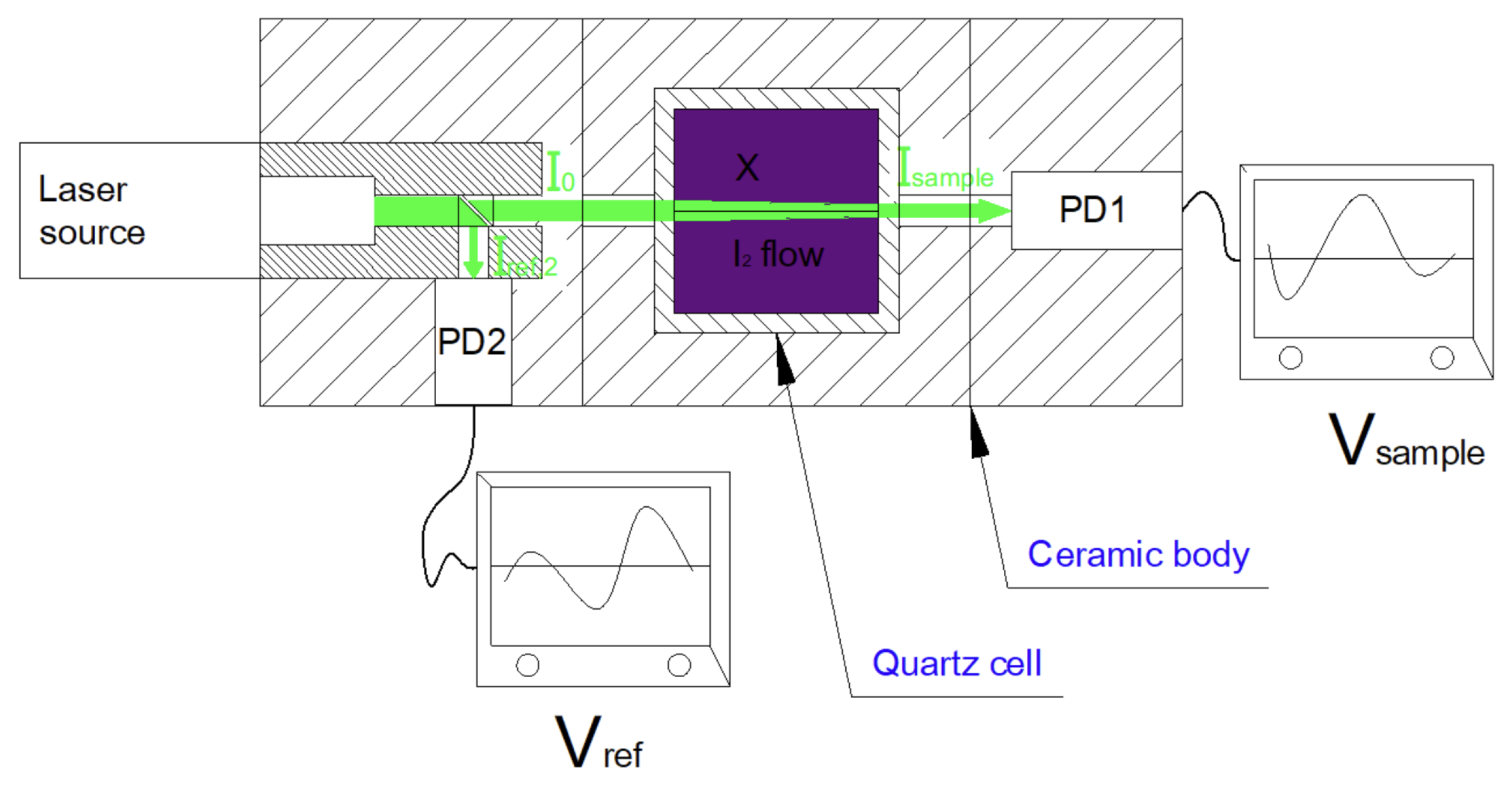
Figure 1 depicts the practical implementation of the concentration measurement of gas molecules. It consists of a transparent vial containing the gas sample, a monochromatic light source, and a photon detector such as a photodiode.
The validity of Lambert’s law is strictly related to the monochromaticity of the radiation incident on the sample, and, in the case of molecular iodine, the maximum of absorption is centered on the green radiation in the visible spectrum (around 520 nm). The availability of solid-state laser modules that emit green light at the absorption wavelength of molecular iodine is particularly advantageous. The light beam emitted by the laser modules not only has the advantage of being sufficiently monochromatic, but it is also collimated, allowing direct coupling with the detection system without the need for further optical collimation systems.
The photodiode signal is proportional to the radiation intensity and is converted to a voltage and amplified. The ratio I 0 / I is calculated as:
I 0 I = I r e f I s a m p l e = ( V r e f V z e r o ) ( V s a m p l e V z e r o ) ,
where the subscript “ref” refers to a reading without vapor, zero to the voltage obtained when no light reaches the detector (resulting from the photodiode dark current), and “sample” is related to the measurement performed in the presence of vapor. Combining Equations (4) and (5) permits obtaining the absorbance A from voltage measurements.

3. Mass Flowmeter Development

This section describes the development process of the iodine mass flowmeter, including its architecture and operational requirements, the sizing of the fluidic line, the design of the telemetry and control board, and the mechanical implementation.

3.1. Requirements

The main requirements that guided the development phase of the MFM are the following:
  • The device must be capable of measuring iodine mass flow rate between 3 mg/s and 15 mg/s, with an accuracy of 0.5 mg/s.
  • In order to avoid clogging of the iodine line, the temperature of the iodine-wetted surfaces must be kept in the range of 90 °C and 115 °C, with an accuracy of 0.5 °C.
  • The light source of the system must be a laser source with a wavelength between 505 nm and 540 nm, a range where iodine has the maximum absorption.
  • The thermal throttle must be sized so as to assure that the flow reaches sonic conditions at the outlet of the thermal throttle.
  • All materials used to build the device must ensure proper compatibility with iodine and high-vacuum conditions.
  • The main body materials must have high thermal conductivity to ensure a proper temperature homogeneity between the cell and the thermal throttle.

3.2. Mass Flowmeter Architecture

As stated in the previous section, c and A are related through the molar absorption coefficient, which is a function of the wavelength λ . An ideal source of light has a constant intensity. However, in practice, solid-state laser sources, even in a properly controlled environment, emit radiation with little variation in intensity. In order to overcome the natural drift of the laser radiation intensity, a beamsplitter is positioned between the laser and the spectrophotometric cell to perform a simultaneous measurement of the reference and the sample signals, using two detectors, as shown in Figure 1. By doing so, the light intensity of the reference signal I r e f (without iodine flow) becomes proportional to I ( r e f , 2 ) , i.e., the light intensity incident on the photodiode PD2:
I r e f = K r · I ( r e f , 2 ) .
As a result, the absorbance can be expressed as
A ( λ ) = l o g 10 V P D 2 V ( z e r o , 2 ) V P D 1 V ( z e r o , 1 ) + l o g 10 K r = ε ( λ ) l c ,
where the factor K r is constant regardless of the operating point of the mass flow meter, which is calculated upon calibration of the device.

3.3. Mechanical Design

This section describes the process of designing the main components of the laser absorption mass flow meter. It describes the methodology used to study the fluid line and the rationale behind the selection of the optical components. It is worth remarking that several aspects regarding the thermal design, in particular the selection of the main body material as well as the heaters’ design and the temperature sensor positioning, have been left out of the present proceedings, but nevertheless remain fundamental for the system’s proper operation.

3.3.1. Fluid Line

The design of the mass flowmeter fluidics is a fundamental step in defining the mass flowmeter, the conditions necessary to achieve a choked condition at the end of the thermal throttle, and the accuracy of the mass flow rate measurement. The main dimensions to define are the channel cross-section and length of the spectrophotometric cell, the optimal position for measuring absorbance, and the internal diameter and length of the thermal throttle. To perform the analysis and guide the design of the fluidic components, a 1D steady gas dynamic model has been set up using the influence coefficient method, based on the model described in [3], which considers the vapor generation process within the tank and the compressible flow along the line and the mass flowmeter, including viscous losses and heat exchange with the walls.
The model assumes that iodine is generated in a cylindrical tank with controlled temperature, in which solid grains of iodine are in phase equilibrium with vapor. By controlling the temperature of the tank, vapor pressure varies according to the Clausius–Clapeyron relation. The generated vapor enters the pipe, which connects the tank with an on–off valve (represented as a localized pressure loss) and to the mass flowmeter inlet. Within the MFM, it goes through the spectrophotometric cell, where the flow thermalizes with the cell casing, whose temperature is controlled, and the absorption measurement is carried out. Then the cell is connected to a capillary pipe, called a thermal throttle, in which the viscous losses and the heat exchange effects are augmented, forcing the occurrence of a sonic condition at the outlet, which is connected to the downstream pipe of the MFM, leading to the thruster. Along the whole domain, iodine properties evolve due to the heat exchange and vapor viscosity. Downstream of the sonic section, we estimate the pressure at the thruster (or neutralizer) inlet connection by considering an expansion from the TT outlet, treating it as a choked nozzle, including pressure losses. For details on how the model is discretized and solved, as well as physical assumptions regarding the calculation of the friction factor or the influence of laminar flow development on the Nusselt number, refer to [3].
Using the described model, a parametric study permitted sizing the thermal throttle, i.e., defining its length and internal diameter as well as its nominal operating temperature.

3.3.2. Optical Design

The optical design of the device includes the selection of the laser source; the beam splitter used to divide the light flow into the main and the reference beams to convey it across the iodine flow; and the sensors used to measure the light intensities of both beams.
The selected laser source was a laser module with a power of 4 mW and a wavelength of 520 nm. A 70/30 beam splitter permitted optimizing the sensitivity of the system to iodine variations while keeping a good capability of compensating for laser intensity variations. A quartz cell with 10 mm internal width is permitted to have a sufficiently long light path and to have a channel cross-section much larger than that of the thermal throttle so as to guarantee conditions close to stagnation in the region where absorption is measured.

3.4. Electronics Design

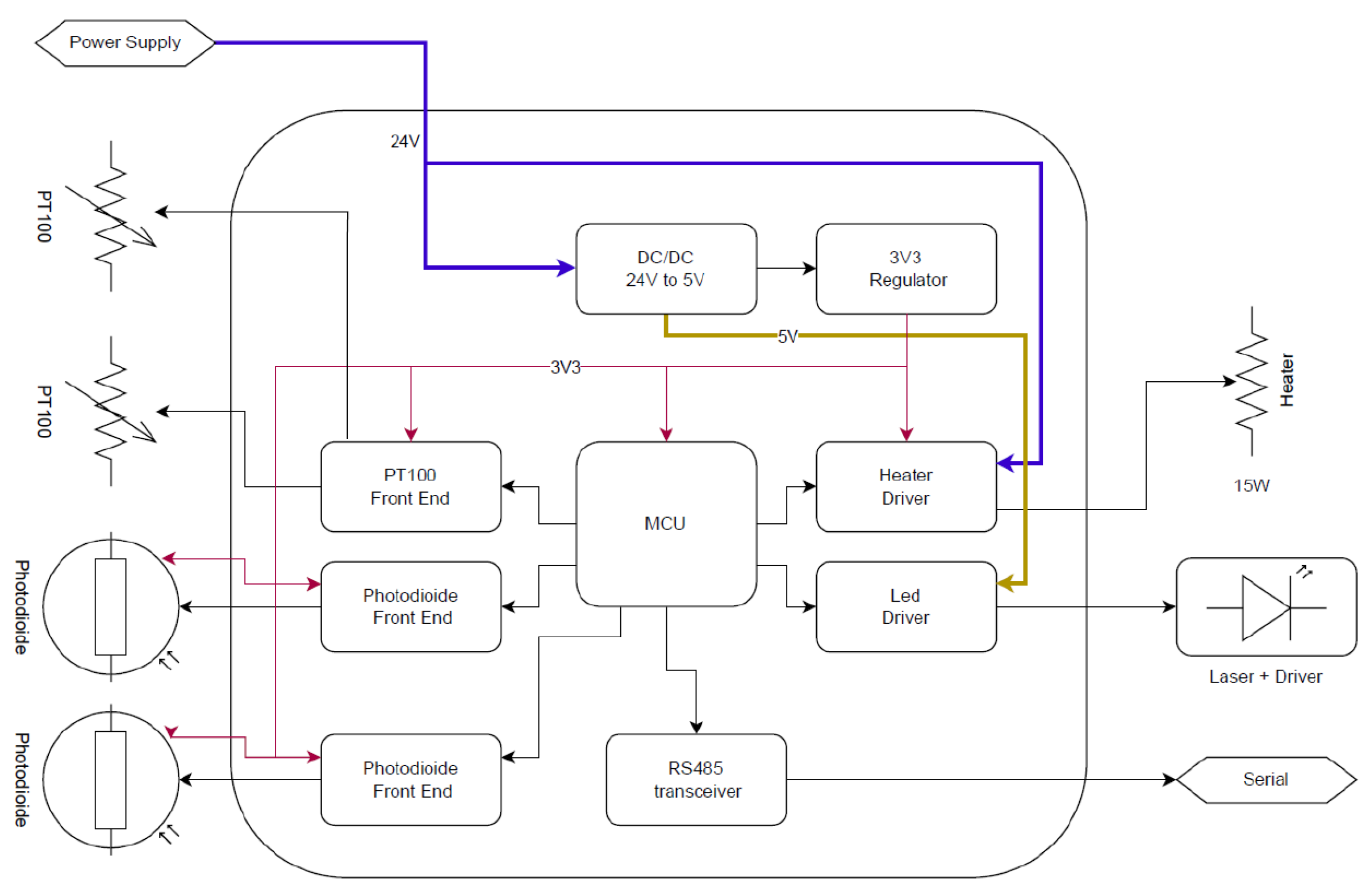
The MFM control and data transmission unit is based on a microcontroller that handles the hardware peripherals, implements closed-loop temperature regulation of the MFM body, and communicates via an RS485 serial line. The controller is powered by a 24 VDC supply (up to 15 W), mainly used by the heater module, and is designed to operate up to 100 °C in air. The system block diagram is shown in Figure 2. The power supply stage provides 5 V for the analog front-end circuits and laser driver and 3.3 V for the MCU. A programmable electronic fuse protects the heater driver in case of a fault. The remaining sections are the PT100 front end, the photodiode stage, and the heater/laser driver. PT100 acquisition is performed via a constant-current front-end, while photodiode readout uses an integrated transimpedance amplifier. The heater driver is based on a high-side protected switch to ensure safe operation.

4. Preliminary Experimental Characterization

The following section presents the preliminary mass flow meter experimental campaign carried out by the MFM prototype. The campaign consisted of two phases, the first one aimed at verifying the capability of the device to measure light absorbance and validating the design of the optics and acquisition electronics. The second phase consisted of a characterization and calibration test in which the system operated under vacuum conditions, and iodine mass flow rate measurements were taken to later calibrate the proportionality constant K.

4.1. Absorbance Measurements

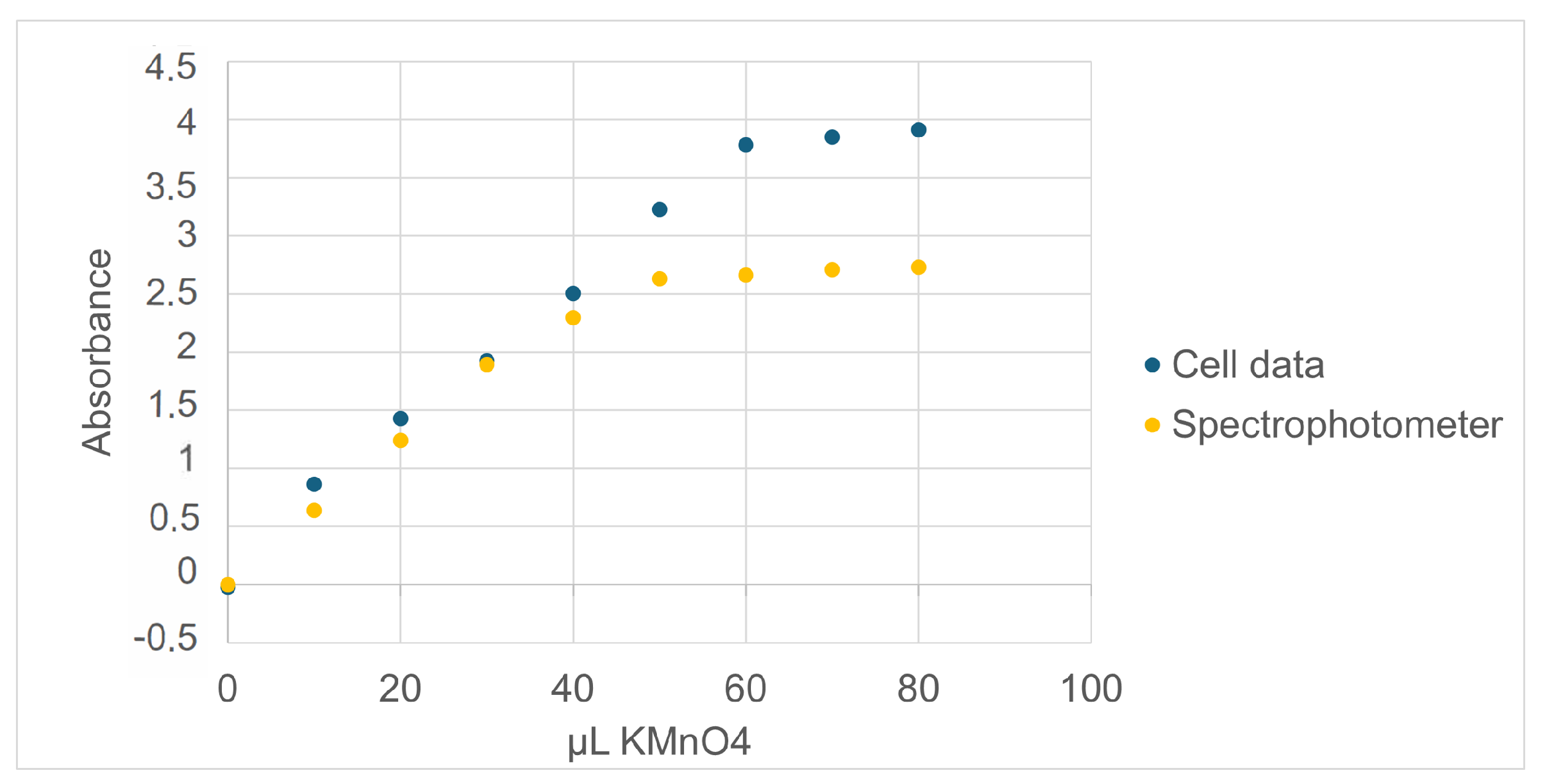
The spectrophotometric part of the flowmeter was validated at ambient temperature and pressure by replacing the flow cell with an identical sealed spectrophotometric cell, filled from time to time with aqueous solutions of potassium permanganate at increasing concentrations. The potassium permanganate gives a violet-colored aqueous solution with absorption of radiation at the same laser emission wavelength. The MFM absorbance values of each solution were then compared with the absorbance values measured with a traditional spectrophotometer set at the same wavelength of the laser radiation. The results are summarized in Figure 3. The benchtop spectrophotometer used for comparison is a Pharmacia Novaspec II.
The graph shows excellent agreement of absorbance values up to the value of 2. For higher absorbance values, the spectrophotometric part of the MFM performs better, as it is linear up to the value of 3.5.

4.2. Flow Measurement Test Setup

The characterization and calibration of the iodine flow meter were carried out within a modular stainless-steel vacuum chamber with an internal diameter of 22 cm and a total length of 100 cm. It is equipped with a 100 l s diffusion pump and an oil-sealed mechanical pump, which together ensure a base pressure of approximately 10−5 mbar. The vacuum level is monitored by an Edwards Wide Range Gauge (WRG-S) connected to a dedicated data acquisition system. For primary vacuum operation, the gate valve remained closed, and the chamber was connected to the mechanical pump. In this configuration, a Pyrex glass cryogenic trap was installed between the chamber and a dedicated rotary pump to collect and visually detect any possible iodine leakage from the reservoir or piping.
The mass flow meter has been clamped to a dedicated structure inside the vacuum chamber, while the iodine tank is positioned outside the vacuum chamber by means of a heated pass-through in the chamber wall. The tank is made of a brass tube externally heated by a wire resistance and connected to a manually operated ball valve. The tank and valve assembly are housed within an external oven to ensure uniform heating of all components. The pipeline entering the chamber is heated independently and terminates at the inlet of the mass flow meter. The tank, with a total capacity of approximately 75 mL, can store up to 300 g of solid iodine. A rack of three Gefran 1350 PID controllers independently controls the temperature of the tank and valve, situated outside the vacuum chamber, and of the feedthrough, as well as of the pipeline inside the chamber. The PID controllers use a Pt100 sensor to measure the tank temperature and type K thermocouples for the feedthrough and internal line temperatures. The three heating systems can operate at different setpoints in the range 50–115 °C with an accuracy of less than 0.5 °C. The internal pipeline is covered with multilayer insulation (MLI) to improve temperature homogeneity.

4.3. Experimental Results

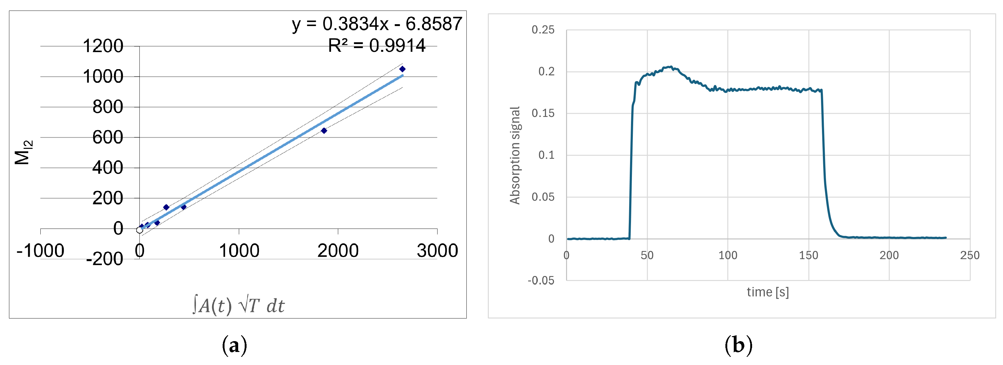
The mass flow measurement for the characterization of the MFM has been carried out under primary vacuum conditions. When the cell reached a steady temperature, the photodiode’s signal was acquired for 2 min to verify the stability of the signal. The acquired signal demonstrated itself to be stable in time, without any evidence of drift, observed during preliminary tests lasting longer than 10 min. The noise content is also low, as a standard deviation of the signal results in 9.3 × 10⁻⁴. These results demonstrate the stability of the optical setup and of the acquisition electronics in the thermal and vacuum operating conditions. Moreover, the selected setup, using a beamsplitter and a reference photodiode, allows for proper compensation of any oscillations that may occur in the laser output. During the absorption tests, the photodiodes’ signals are acquired for nearly a minute before activating the iodine flow in order to verify that the optical system is in a steady thermal state. The results are reported in Figure 4a, together with the linear regression of the data. During the tests, the tank and cell temperature setpoints were set at 85 °C and 110 °C, respectively. The absorbance profile acquired during the low-flow experiment exhibited the expected time evolution, as reported in Figure 4b: a sharp increase when the valve was opened, a practically constant absorption during the opening time, and a rapid return to the background value just after the closure of the valve. On the other hand, the feeding system showed difficulties sustaining steady flows at high mass-flow-rate values useful for calibration purposes, which is likely due to the reservoir being unable to provide the required amount of iodine vapor at these high flow-rate conditions.

5. Conclusions

The article presents the test activities on the development of a laser-based mass flow meter to be used within the “iFACT-MP” project. The system showed a correct absorbance trend as a function of time for low-flow experiments, where a sharp increase appeared after valve opening, followed by a stable plateau, and then an immediate return to background after closure. For higher flows, the tank was not able to sustain the iodine vapor request, confirming that the evaporation rate could not compensate for the pressure drop caused by the valve opening. Despite this limitation, the MFM proved capable of detecting absorbance variations up to around 10 mg/s and demonstrated a promising new architecture for instantaneous and repeatable iodine flow measurements. Finally, post-test inspection revealed no iodine contamination, confirming the integrity of all exposed components.

Author Contributions

Conceptualization, C.G., M.M.S., D.P., A.C., and F.P.; methodology, M.M.S., C.G., L.B., and D.P.; software, M.M., E.P.; validation, M.M.S., C.G., and A.C.; writing—original draft preparation, C.G., M.M.S.; writing—review and editing, C.G., M.M.S., and D.P.; supervision, F.P. and A.C.; project administration, A.C. and N.G.K.; funding acquisition, N.G.K. an d A.C. All authors have read and agreed to the published version of the manuscript.

Funding

This project has received funding from the Horizon Europe Project 101134963, “iFACT-MP: iodine-Fed Advanced Cusp-Field Thruster for Mid-Power”.

Institutional Review Board Statement

Not applicable.

Informed Consent Statement

Not applicable.

Data Availability Statement

The data that support the findings of this study are available from the corresponding author upon reasonable request.

Conflicts of Interest

N.G.K. was employed by the company Airbus Defence and Space. The remaining authors declare that the research was conducted in the absence of any commercial or financial relationships that could be construed as a potential conflict of interest.

References

  1. Szabo, J.; Robin, M.; Paintal, S.; Pote, B.; Hruby, V.; Freeman, C. Iodine Plasma Propulsion Test Results at 1–10 kW. IEEE Trans. Plasma Sci. 2015, 43, 141–148. [Google Scholar] [CrossRef]
  2. Dankanich, J.; Szabo, J.J.; Pote, B.; Oleson, S.R.; Kamhawi, H. Mission and System Advantages of Iodine Hall Thrusters. In Proceedings of the 50th AIAA/ASME/SAE/ASEE Joint Propulsion Conference, Cleveland, OH, USA, 28–30 July 2014. [Google Scholar] [CrossRef]
  3. Saravia, M.M.; Bernazzani, L.; Ceccarini, A.; Vinci, A.E.; Paganucci, F. Modeling and Characterization of a Thermally Controlled Iodine Feeding System for Electric Propulsion Applications. Aerospace 2020, 7, 10. [Google Scholar] [CrossRef]
  4. Saravia, M.M.; Vinci, A.E.; Moriconi, B.; Bernazzani, L.; Ceccarini, A.; Paganucci, F. Absorption-based Laser Mass Flow Meter for Iodine Feeding System for Electric Propulsion. In Proceedings of the 2020 IEEE 7th International Workshop on Metrology for AeroSpace (MetroAeroSpace), Pisa, Italy, 22–24 June 2020; pp. 276–281. [Google Scholar] [CrossRef]
  5. Rafalskyi, D.; Martínez, J.M.; Habl, L.; Zorzoli Rossi, E.; Proynov, P.; Boré, A.; Baret, T.; Poyet, A.; Lafleur, T.; Dudin, S.; et al. In-orbit demonstration of an iodine electric propulsion system. Nature 2021, 599, 411–415. [Google Scholar] [CrossRef] [PubMed]
Figure 1. Scheme of a spectrophotometric cell setup for concentration measurements, using a two-photodiode architecture.
Engproc 133 00176 g001
Figure 2. Block diagram of the controller and data transmission unit.
Engproc 133 00176 g002
Figure 3. Absorption of potassium permanganate solution: comparison of MFM cell vs. benchtop spectrophotometer.
Engproc 133 00176 g003
Figure 4. Experimental results: (a) Linear regression of data: A ( t ) T d t vs. immobilized iodine mass. (b) Example of absorption signal for low-flow experiment.
Engproc 133 00176 g004
Disclaimer/Publisher’s Note: The statements, opinions and data contained in all publications are solely those of the individual author(s) and contributor(s) and not of MDPI and/or the editor(s). MDPI and/or the editor(s) disclaim responsibility for any injury to people or property resulting from any ideas, methods, instructions or products referred to in the content.