Proceeding Paper

Modeling Comparison of a Two-Phase Mechanically Pumped Loop with a Conventional Ethylene Glycol Water Single-Phase Mechanically Pumped Loop for Fuel-Cell Cooling in TheMa4HERA †
by
Tim A. F. van de Weijer
1,*,
Johannes van Es
1,*,
Henk Jan van Gerner
1,
Arne K. te Nijenhuis
1,
Julian Biesheuvel
1,
Guilhem Delpu
2,
Fatima Cherdouh
2,
Esli Trejo Peimbert
2,
Ricardo Abib Gantus
2,
Pierre Trolliet
2,
Guillaume Galzin
2 and
Laurent Labaste Mauhe
2
1
NLR—Royal Netherlands Aerospace Centre, 1059 CM Amsterdam, The Netherlands
2
Liebherr-Aerospace Toulouse SAS, 31016 Toulouse, France
*
Authors to whom correspondence should be addressed.
Presented at the 15th EASN International Conference, Madrid, Spain, 14–17 October 2025.
Eng. Proc. 2026, 133(1), 173; https://doi.org/10.3390/engproc2026133173
Published: 26 May 2026

Abstract

The fuel-cell (FC) technology currently being considered to reduce aircraft greenhouse gas emissions may require large and heavy cooling systems. The paper introduces the two-phase (2 Φ ) Mechanically Pumped Loop (MPL) for FC cooling and compares it numerically with the conventional Ethylene Glycol Water (EGW) single-phase (1 Φ ) cooling system for a 1.2 MW heat-dissipation load. Considering an operating temperature of 90 °C, the system mass of the 2 Φ MPL with and without an accumulator is found to be, respectively, 33% and 64% lower than the EGW system. Furthermore, the frontal area of the ram air heat exchanger (HX) was found to be 19% smaller, reducing ram air drag. An increase of the operating temperature to 130 °C was found to reduce the cooling system mass by 21% for the 1 Φ MPL, and 22 to 29% for the 2 Φ MPL. The frontal area of the ram air HX was found to be reduced by 44% and 40% for the 1 Φ and 2 Φ MPL, respectively. These results demonstrate the considerable performance gain of the 2 Φ MPL over the 1 Φ MPL for FC cooling, and the benefits of increasing the operating temperature for the cooling system.

1. Introduction

1.1. Background

Amid efforts to significantly reduce aviation greenhouse gas emissions, the transition to hydrogen as a fuel is being widely researched. Among the various fuel cell types, low-temperature proton exchange membrane fuel cells (LT-PEMFC) are regarded as promising because of their high power density and specific power [1], as well as their technological readiness in comparison to other fuel-cell technologies [2]. However, the high heat-dissipation loads and typical operating temperature of 90 °C associated with LT-PEMFCs may lead to large and heavy fuel cell cooling systems. In this paper, a two-phase (2 Φ ) Mechanically Pumped Loop (MPL) is compared with an Ethylene Glycol Water (EGW) based single-phase (1 Φ ) MPL to quantify the performance benefits of the 2 Φ MPL for fuel-cell cooling. The MPL comparison is performed for a 1.2 MW heat load at 90 °C and at 130 °C to quantify the effect of an elevated operating temperature on the MPL. The latter temperature is attainable when using proton exchange membranes developed for higher temperatures [2].

1.2. Introduction to Mechanically Pumped Loops

In conventional fuel-cell (FC) cooling loops, an EGW mixture is transported by a pump to the fuel cells. Here, the waste heat is absorbed in the form of sensible heat. Then, the fluid is transported to a ram air heat exchanger (HX), where the waste heat is dissipated into the air. The fluid is transported again to the fuel cells, forming a continuous recirculating loop. Such a system will be referred to as a 1 Φ MPL in the remainder of this paper.
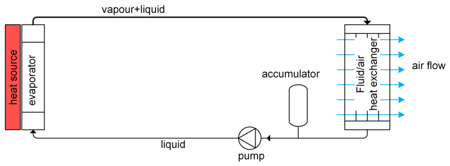
The principle of a 2 Φ MPL is similar in that it transports heat from a source to a sink. Whereas the EGW mixture absorbs/rejects heat in the form of sensible heat, maintaining its liquid phase, the fluid in a 2 Φ MPL utilizes its heat of evaporation. The working fluid is transported as a liquid by the pump to the evaporator, where it absorbs the waste heat through (partial) evaporation. The resulting 2 Φ fluid, comprising both vapor and liquid, is then transported to the condenser (i.e., ram air HX), where the fluid condenses back into a liquid as the waste heat is dissipated into the air. In Figure 1, the schematic drawing of a simple 2 Φ MPL system is provided.
The accumulator illustrated in Figure 1 regulates the pressure in the system and allows for expansion of the fluid as it is (partly) evaporated. Pressure regulation is important because the boil-off temperature is a function of pressure, thereby controlling the evaporation temperature on the evaporator cold plate. Recent research has shown that a 2 Φ MPL can also be operated without an accumulator, reducing system mass significantly [3].
Figure 1. Schematic of a simple air cooled 2 Φ MPL. Reproduced from [4].
Engproc 133 00173 g001
The use of a 2 Φ MPL results in much lower mass flows, reducing tubing diameter and thereby system mass. The reduced mass flow also allows for smaller and lighter pumps, as well as lower pump power requirements. Furthermore, the heat transfer coefficient is typically much higher when condensing/evaporating, aiding heat transfer. An example of the successful integration of a 2 Φ MPL is the Alpha Magnetic Spectrometer, which is mounted on the International Space Station and has been successfully operational since 2011 [5].

2. System Configuration and Analysis

2.1. System Architecture

A schematic drawing of the architecture analyzed in this paper is provided in Figure 2. In this paper, four parallel FC stacks are considered, each with a fuel cell efficiency of 50% and a power of 300 kW. The geometry of the channels through which the fluids flow (hereafter referred to as evaporators) is based on the geometry in [4]. The number of parallel evaporator channels is scaled with the power reported in [4]. The ram air HXs are modeled as louvered crossflow plate-fin heat exchangers.
The cryogenically stored hydrogen must first be conditioned before being supplied to the FCs. This conditioning may be achieved by electrical heating; however, the required electrical power equals approximately 8% of the electrical power generated by the FCs [6], diminishing overall aircraft performance. Alternatively, one can achieve the desired conditioning utilizing the waste heat from the FC. This reduces the heat load that needs to be dissipated into the air, thereby reducing the size and mass of the ram air HX and, consequently, drag. These reasons motivate the implementation of a hydrogen heat exchanger (H2HX) in the cooling loop.
The placement of the hydrogen heat exchanger has a considerable influence on the performance of the MPL and its associated components. Compared to placement of the H2HX on the cold/liquid side of the MPL, placement on the hot/two-phase side decreases the size and mass of the H2HX and reduces the tendency for fluid freezing due to a higher fluid temperature.
However, the H2HX in this configuration also cools the cooling fluid before it enters the ram air HX. For the 1 Φ MPL, this results in a reduced ram air HX inlet temperature and consequently a reduced temperature differential with the air. For a given heat dissipation, this results in a heavier HX with a larger frontal area, increasing overall aircraft drag. For the 2 Φ MPL, the vapor mass fraction at the ram air HX inlet is lowered, resulting in a lower heat transfer coefficient and increasing the portion of the heat exchanger in which the liquid is subcooled. Again, increasing the mass and required frontal area of the HX.
The H2HX itself has a low mass relative to the ram air HX, as will be shown in Section 3. As a result, the increase in the ram air HX mass and frontal area is expected to have a larger penalty on aircraft performance. This motivates the placement of the H2HX on the cold/liquid side of the MPL at the cost of a larger tendency for fluid freezing. This is especially critical when using EGW as it has a freezing point of 45 °C. Freezing is less critical with 2 Φ fluids as they typically have significantly lower freezing points (< 80 °C). In this paper, freezing of the fluid is neglected, but this should be considered in future work.
The H2HX is modeled as an annular heat exchanger with the MPL fluid flowing through the center channel. Through a thin wall, heat is transferred to the hydrogen, which flows in the surrounding parallel channels. The reader is redirected to [6] for more information on the modeling of the H2HX as performed in the HyPoTraDe project.

2.2. 2Φ MPL Fluid Selection

The selection of the fluid is vital to the development of a 2 Φ MPL as it determines its performance. The saturation temperature of the fluid is directly correlated with pressure, and, therefore, the pressure drop must be minimized. Additionally, to reduce system mass, the tubing diameter should be minimized. However, a reduction in the tubing diameter increases the pressure drop and vice versa. Therefore, a fluid must be chosen with a high heat of evaporation to minimize mass flow and have properties that minimize pressure losses. Furthermore, one should consider factors such as material compatibility, flammability, global warming potential, etc. Based on these considerations, methanol has been chosen for the 2 Φ MPL operating at 90 °C and ethanol for the MPL operating 130 °C. The corresponding saturation pressures are 2.56 bar(a) and 5.73 bar(a). For more information on the method of fluid selection, the reader is invited to read [4,7].

2.3. System Analysis

The cooling systems have been designed and analyzed using the steady state solver of the NLR cooling system analysis tool. This tool simulates the MPL by solving the 1D mass and enthalpy equations [4]. For more information on the used friction and heat transfer correlations on the MPL side, the reader is referred to [8,9]. Refs. [10,11] are used to estimate the friction factor and heat transfer coefficient on the air side of the ram air HX.
The systems are designed such that the fluid: (1) does not exceed the operating temperature (i.e., 90 °C or 130 °C); (2) has a maximum temperature differential along the evaporator of 15 °C; and (3) exits the evaporator with a maximum vapor mass fraction of 0.35 in case of the 2 Φ MPL. The ram air HXs have been designed to (1) limit the static pressure drop of air to 1.5   k Pa and (2) have a fan power of 30 k W at 90 °C and 0 k W at 130 °C during the design flight case. The H2HX is designed to condition the H2 to 60 °C with a maximum pressure drop of 0.25 bar over the H2HX. The design flight case was taken to be at take-off (i.e., some ram air available), and the additional fan power required when stationary at full power is assumed available. The corresponding fan power was found to be less than 45 k W and 20 k W when operating at 90 °C and 130 °C respectively.
In the analysis tool version 2.3, mass estimation is performed by decomposing the system into its components. For all components, except the pump, mass is estimated based on its geometry and material properties. The used estimations are identical to the approach provided in Appendix B of [4]. For the H2HX, the volume of H2HX material is multiplied by a density of 2700 kgm−3, the outer diameter has been increased artificially to account for electrical heating elements, which are required during FC startup.

3. Results

3.1. Baseline: 1Φ EGW Operating at 90 °C

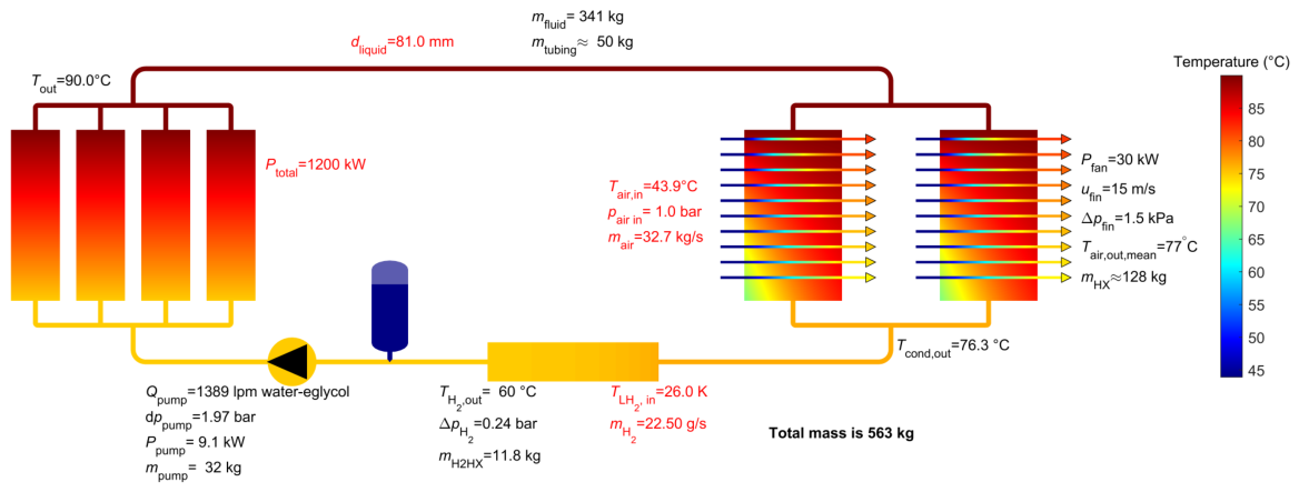
Figure 3 shows the calculated temperature distribution of the 1 Φ MPL. The red text in Figure 3 indicates that the parameters are provided as input, while black is calculated. The EGW mixture, transported by the pump, absorbs waste heat from the FC stacks and heats up from 75 °C to 90 °C. The fluid is pumped to the ram air HX, in which the waste heat is dissipated into the air. As the waste heat is also used to condition the hydrogen, the fluid is cooled to 76.3 °C in the ram air HX. In the H2HX, the fluid is cooled back down to 75 °C before entering the pump and FCs again.
The total system mass for the 1 Φ MPL at 90 °C is calculated to be 563 kg, of which 341 kg is accounted for by the EGW mixture and is thereby the largest contributor to the overall system mass (61%). This is a direct consequence of the defined temperature difference over the FCs and the defined pressure drop over the system. When the allowable pressure drop and/or temperature difference increases, the tubing diameter can be decreased, reducing the volume and mass of the fluid in the system. The second-largest contributors to system mass are the ram air HXs, which, at 128 kg, account for 23% of the system mass.

3.2. 2Φ Methanol Operating at 90 °C

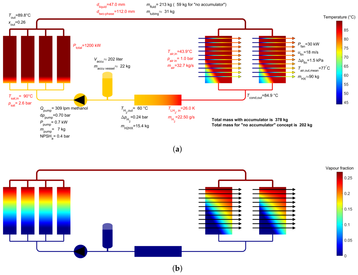
The calculated temperature and vapor mass fraction distributions along the 2 Φ methanol system are provided in Figure 4a,b respectively. From these figures, it can be observed that the fluid enters the evaporators as a subcooled liquid. In the evaporator, the fluid is heated to the saturation temperature (90 °C) and subsequently evaporation is initiated, increasing the vapor mass fraction from 0 to 0.26. This is less than the maximum vapor mass fraction as discussed in Section 2.3. In the ram air HX, methanol is condensed until the liquid is saturated, and then the liquid gets subcooled. The ram air HX has been designed such that the mixed fluid exiting the ram air HX is subcooled but close to saturation. The decision was made to do so for numerical reasons, as oscillations and divergence were observed when a subcooled liquid was not attained.
For a vapor mass fraction of 0.35, it was observed that the 15 °C temperature differential along the evaporators was exceeded due to excessive subcooling at their inlets. By reducing the vapor mass fraction, the mass flow is increased. The heat energy transferred from the MPL to the hydrogen (approximately 8% of total thermal power) is now distributed over a larger amount of mass; hence, the amount of subcooling is reduced, raising the temperature at the inlets of the evaporators. Consequently, the two-phase tubing diameter is increased to maintain pressure losses between the evaporators and the ram air HX, thereby increasing the tubing and fluid mass.

3.3. 2Φ Methanol vs. 1Φ EGW Operating at 90 °C

In Table 1, a comprehensive overview of the characteristics for all four systems is provided. When comparing the 1 Φ and 2 Φ pump characteristics at 90 °C, it is found that the pump power required for the 2 Φ MPL is reduced from 9.1 kW to 0.7 kW. This is a consequence of the drastic reduction in pump volume flow (−77%) and the decrease in pressure drop from 1.97 bar to 0.7 bar. Therefore, a smaller and lighter pump may be used in the 2 Φ MPL. Within the two-phase region, the inner diameter of the tubing is found to increase from 81 to 112 mm, whereas a significant reduction in the liquid tubing is observed from 81 to 47 mm. This leads to a decrease in the tubing mass from 50 kg to 31 kg, and more substantially, a considerably lower fluid mass (213 kg vs. 341 kg). However, a further mass reduction can be achieved by implementing a 2 Φ MPL design without an accumulator. The fluid in the two-phase tubing evaporates during startup, pushing liquid into the accumulator. This results in a large (202 liters) and heavy (22 kg) accumulator. By eliminating the accumulator, the fluid mass is reduced to 59 kg, which equals only 17% of the 1 Φ MPL fluid mass.
The ram air HX is found to decrease in mass (38 kg reduction) and frontal area (−19%). In contrast to the 1 Φ MPL, where the fluid temperature decreases along the ram air HX, the methanol condenses at a constant temperature, resulting in a larger temperature differential with the air. Additionally, the heat transfer coefficient of the condensing methanol is larger than for the 1 Φ EGW MPL. The higher heat transfer coefficient and temperature differential increase the heat flux, reducing the required surface area and thus facilitating a smaller HX, which reduces both frontal area and mass.
The total system mass for the accumulator-based methanol loop is calculated to be 378 kg (−33%) or 202 kg (−64%) without the accumulator. Considering that the proposed aircraft in the TheMa4HERA project requires a heat dissipation of 2.4 MW ( 1.2 MW per side), a total cooling system mass reduction of 370 or 722 kg is obtained. Additionally, the drag over the ram air HX is reduced, given the 19% frontal area reduction. Hence, integration of a 2 Φ MPL is found to provide a considerable performance gain over the 1 Φ MPL at both system and aircraft level, highlighting the potential of a 2 Φ MPL as FC cooling system.

3.4. Effect of 1Φ MPL Operating Temperature

Elevation of the FC operation temperature to 130 °C is calculated to reduce the 1 Φ system mass by 121 kg from 563 to 442 kg ( 21 %). This reduction can be primarily attributed to two factors: (1) ram air HX size and (2) tubing diameter.
The elevated operating temperature leads to an increased temperature differential, raising the heat flux and facilitating a smaller ram air HX. This yields a total ram air HX mass saving of 62 kg (−48%), and frontal area reduction of 44%.
The tubing diameter has been found to be decreased (76 mm vs. 81 mm). As a result, the tubing mass has decreased by 7 kg, and the fluid mass is found to be reduced by 57 kg.
Notably, the pump appears to be unaffected by the elevated operating temperature. Even though the fluid properties of the EGW mixture vary with temperature, the pump volumetric flow rate is similar, and consequently, the pump mass and power are constant.

3.5. Effect of 2Φ MPL Operating Temperature

The difference in operating temperature of the 2 Φ system is found to yield a system mass reduction of 83 kg (−22%) and 58 kg (−29%) for the configurations with and without accumulator respectively. Again, the mechanism discussed in Section 3.3 and Section 3.4 results in a notable HX mass reduction of 39 kg and frontal area reduction of 43%.
In comparison to the 90 °C 2 Φ MPL with accumulator, both the liquid and two-phase tubing inner diameter are decreased. This results in a decreased system volume, decreasing the fluid mass by 45 kg and reducing the tubing mass by 8 kg. Interestingly, with the “no accumulator” configuration, the fluid mass is less affected. This has been found to be caused by a higher mean fluid density in the MPL.
Operation of the 2 Φ MPL at 130 °C also comes with disadvantages relative to the 2 Φ MPL at 90 °C. First of all, the MPL requires a larger pump volume flow. Secondly, δ T δ p s a t is lower for ethanol at 130 °C relative to methanol at 90 °C, meaning that a larger pressure drop is warranted before the 15 °C  Δ T over the fuel cell is reached. As a result, a heavier pump is required, and more power must be supplied to operate the MPL. Despite this, the required pump size, mass, and power remain considerably lower than for the 1 Φ MPLs.
Lastly, comparison of the 1 Φ and 2 Φ MPL at 130 °C finds that the system mass is again significantly reduced (−33% and −67% for the configuration with and without accumulator, respectively). Hence, demonstrating the performance gain of the 2 Φ MPL at 130 °C as well.

4. Discussion

In this paper, single-phase and two-phase cooling systems are designed and compared to each other for a 1.2 MW FC thermal load, operating at 90 °C and 130 °C. It has been found that, even while the fan power is reduced from 30 kW to 0 kW for the operating temperature of 130 °C, the elevation of the operating temperature from 90 °C to 130 °C reduced the system mass by 21% for the 1 Φ MPL and 22–29% for the 2 Φ MPL. Apart from a decrease in drag penalty due to a lower system mass, an additional drag reduction is expected due to the 40–44% reduction in the ram air HX frontal area. These results highlight the benefits of increasing the operational FC temperature on the performance of the cooling system.
Furthermore, it has been found that, relative to an EGW based 1 Φ MPL, the implementation of a 2 Φ MPL features a mass reduction up to 64%, as well as reducing the ram air HX frontal area (−19% at 90 °C). Therefore, the results presented in this paper show that the 2 Φ MPL improves the FC cooling system performance and, consequently, the aircraft’s performance compared to the 1 Φ MPL. However, the implementation of 2 Φ MPL may also come with challenges. Flow distribution across parallel flow branches and gravity effects may become problematic if not considered during the design stage [4]. Although the experiments of [3] show that with careful design, a 2 Φ MPL can be successfully operated under different orientations. Furthermore, material compatibility between the hardware and working fluid may be poor. The compatibility of ethanol and methanol is, for example, known to be poor with certain aluminum alloys under certain conditions. Lastly, the 2 Φ MPL configuration without an accumulator needs further analysis to assess aircraft integration feasibility. Control of the MPL is, for example, more complex, as the ram air needs to be controlled to set the desired saturation temperature [3]. Nonetheless, the considerable performance gain of the 2 Φ MPL warrants further research to overcome these challenges.

Author Contributions

Conceptualization, T.A.F.v.d.W.; methodology, T.A.F.v.d.W., H.J.v.G. and A.K.t.N.; software, T.A.F.v.d.W., J.B., H.J.v.G. and A.K.t.N.; validation, T.A.F.v.d.W.; formal analysis, T.A.F.v.d.W.; investigation, T.A.F.v.d.W.; resources, T.A.F.v.d.W. and J.v.E.; data curation, T.A.F.v.d.W.; writing—original draft preparation, T.A.F.v.d.W.; writing—review and editing, T.A.F.v.d.W., A.K.t.N., J.v.E., G.D., F.C., E.T.P., R.A.G., P.T., G.G. and L.L.M.; visualization, T.A.F.v.d.W., H.J.v.G., and J.v.E.; supervision, J.v.E.; project administration, J.v.E.; funding acquisition, J.v.E. All authors have read and agreed to the published version of the manuscript.

Funding

This research was funded by the European Union, under Grant Agreement Number 101102008. Views and opinions expressed are, however, those of the authors only and do not necessarily reflect those of the European Union or Clean Aviation Joint Undertaking. Neither the European Union nor Clean Aviation JU can be held responsible for them.

Institutional Review Board Statement

Not applicable.

Informed Consent Statement

Not applicable.

Data Availability Statement

The input parameters for the simulations will be made available upon request by the corresponding authors.

Conflicts of Interest

Authors Guilhem Delpu, Fatima Cherdouh, Esli Trejo Peimbert, Ricardo Abib Gantus, Pierre Trolliet, Guillaume Galzin, and Laurent Labaste Mauhe were employed by the company Liebherr-Aerospace Toulouse SAS. The remaining authors declare that the research was conducted in the absence of any commercial or financial relationships that could be construed as a potential conflict of interest. The funders had no role in the design of this study; in the collection, analyses, or interpretation of data; in the writing of the manuscript; or in the decision to publish the results.

References

  1. Ayar, M.; Hikmet Karakoc, T. Decision mechanism between fuel cell types: A case study for small aircraft. Int. J. Hydrogen Energy 2023, 48, 23156–23167. [Google Scholar] [CrossRef] [Scilit]
  2. Corti, H.R. Polymer electrolytes for low and high temperature PEM electrolyzers. Curr. Opin. Electrochem. 2022, 36, 101109. [Google Scholar] [CrossRef] [Scilit]
  3. van Gerner, H.J.; Luten, T.; Scholten, S.; Mühlthaler, G.; Buntz, M.-B. Test Results for a Novel 20 kW Two-Phase Pumped Cooling System for Aerospace Applications. Aerospace 2025, 12, 188. [Google Scholar] [CrossRef] [Scilit]
  4. van Gerner, H.J.; Luten, T.; Resende, W.; Mühlthaler, G.; Buntz, M.-b. System Analysis and Comparison Between a 2 MW Conventional Liquid Cooling System and a Novel Two-Phase Cooling System for Fuel Cell-Powered Aircraft. Energies 2025, 18, 849. [Google Scholar] [CrossRef] [Scilit]
  5. van Es, J.; Pauw, A.; van Donk, G.; van Gerner, H.J.; Laudi, E.; He, Z.; Gargiulo, C.; Verlaat, B. Tracker Thermal Control Cooling System commissioning and operational results. In Proceedings of the 43rd International Conference on Environmental Systems, Vail, CO, USA, 14–18 July 2013. [Google Scholar]
  6. te Nijenhuis, A.K.; Pauw, A.; Luten, T.; Van Benthem, R.C.; Tavčar, G. LH2 Conditioning System Design Using a Two-Phase Mechanically Pumped Loop for Fuel Cell System Waste Heat Recovery; Royal NLR, Netherlands Aerospace Centre: Amsterdam, The Netherlands, 2026; manuscript in preparation. [Google Scholar]
  7. van Gerner, H.J.; van Benthem, R.C.; van Es, J. Fluid selection for space thermal control systems. In Proceedings of the 44th International Conference on Environmental Systems, Tucson, AZ, USA, 13–17 July 2014. [Google Scholar]
  8. van Gerner, H.J.; Braaksma, N. Transient modeling of pumped two-phase cooling systems: Comparison between experiment and simulation. In Proceedings of the 46th International Conference on Environmental Systems, Vienna, Austria, 10–14 July 2016. [Google Scholar]
  9. van Gerner, H.J.; Bolder, R.; van Es, J. Transient modeling of pumped two-phase cooling systems: Comparison between experiment and simulation with R134a. In Proceedings of the 47th International Conference on Environmental Systems, Charleston, South Carolina, 16–20 July 2017. [Google Scholar]
  10. Chang, Y.-J.; Wang, C.-C. A generalized heat transfer correlation for louver fin geometry. Int. J. Heat Mass Transf. 1997, 40, 533–544. [Google Scholar] [CrossRef] [Scilit]
  11. Chang, Y.J.; Chang, W.J.; Li, M.C.; Wang, C.C. An amendment of the generalized friction correlation for louver fin geometry. Int. J. Heat Mass Transf. 2006, 49, 4250–4253. [Google Scholar] [CrossRef] [Scilit]
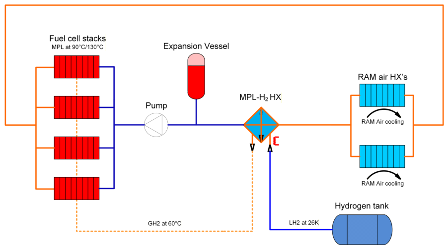
Figure 2. Schematic drawing of MPL in TheMa4HERA. The hydrogen supply system is not considered in the current paper beyond the H2HX and is only shown for illustrative purposes.
Engproc 133 00173 g002
Figure 3. Calculated temperature distribution of the 1 Φ MPL operating at 90 °C.
Engproc 133 00173 g003
Figure 4. (a) Calculated temperature distribution of the 2 Φ MPL operating at 90 °C. (b) Calculated vapor mass fraction distribution of the 2 Φ MPL operating at 90 °C.
Engproc 133 00173 g004
Table 1. Overview of calculated system parameters for the different systems and temperatures.
1 Φ EGW2 Φ Methanol2 Φ Ethanol
90 °C130 °C90 °C130 °C
Pump Δ p [bar]1.972.000.71.00
Pump flowrate[lpm]13891384309339
Pump power[kW]9.19.20.71.1
Pump mass[kg]323278
Ram air HX frontal area[m2]2.521.402.041.22
Ram air HX mass[kg]128669051
Accumulator volume[L]1833202167
Accumulator mass 2[kg]neglectedneglected22 (-) 137 (-) 1
Fluid mass[kg]341294213 (59) 1168 (54) 1
Tubing mass[kg]50433123
H2HX mass[kg]126158
Cooling system mass[kg]563442378 (202) 1295 (144) 1
Mass reduction 3[%]-2133 (64) 147 (74) 1
1 Value in brackets refers to the no-accumulator 2 Φ MPL configuration. 2 Excludes mass of the fluid stored in accumulator, this fluid mass is included under “fluid mass”. 3 Relative to the 1 Φ system at 90 °C.
Disclaimer/Publisher’s Note: The statements, opinions and data contained in all publications are solely those of the individual author(s) and contributor(s) and not of MDPI and/or the editor(s). MDPI and/or the editor(s) disclaim responsibility for any injury to people or property resulting from any ideas, methods, instructions or products referred to in the content.