1. Introduction
The topic of liquid hydrogen powered aircraft has been presented in scientific literature and research for nearly 70 years. The National Advisory Committee for Aeronautics (NACA), the predecessor of NASA, investigated the feasibility of using liquid hydrogen as an aviation fuel as early as 1955 [
1]. Further studies on liquid hydrogen (LH
2)-powered passenger aircraft were conducted by Lockheed for NASA, with results published in 1976 [
2]. The authors concluded that, when compared in terms of energy efficiency and aircraft design, LH
2 offers more advantages for large aircraft. Important contributions to this field were later made by consortium of European institutes and companies, led by Airbus, within the Liquid Hydrogen Fueled Aircraft—System Analysis (CRYOPLANE) project (2000–2002). For medium-range aircraft, multiple tank configurations located both above and behind the passenger cabin were studied. These configurations resulted in longer and higher fuselage along with the need for larger and more aft-placed wings. Combined with an estimated fuel mass between 8 and 12 tons, these changes were predicted to increase operational empty weight of the structure by 20–25% [
3]. Interest in hydrogen-powered flight re-emerged in the late 2010s and early 2020s due to growing awareness of the threats posed by climate change. This resurgence has led not only to increased academic research but also to significant involvement from private and public companies, such as Airbus, ZeroAvia, and Universal Hydrogen, which have introduced development plans and technologies based on hydrogen propulsion [
4,
5,
6].
Project DEMOCRITE (Development of Modular Cryogenic Tank) emerged from the EREA Researchers’ Event held in Warsaw in June 2022. The project focuses on a modular approach to onboard liquid hydrogen (LH2) storage, in which a single large tank is replaced by multiple smaller modules. This concept enables potential tank replacement for maintenance and refueling purposes. The project is collaborative effort among four research institutes: the Łukasiewicz Research Network—Institute of Aviation (Poland), CIRA (Italy), ONERA (France) and INCAS (Romania). It addresses multiple aspects of onboard LH2 storage, including tank placement, maintenance and safety, sloshing simulations, structural health monitoring, material properties, and manufacturing technologies. This paper presents overview of findings from tank module placement analyses and basic safety reviews.
2. Tank Modules Sizing and Placement
2.1. Selection of Target Aircraft
The placement and size of LH
2 tank modules depend on the selected aircraft size and operational range. For very short-range missions with low passenger capacity, a fuel-cell-powered electric propulsion system is a viable solution [
5]. However, for short- to medium-range applications, this powertrain becomes insufficient. For example, for aircraft carrying 40 to 80 passengers over a range of approximately 1000 nmi, ZeroAvia proposes the use of electric turboprop engines powered by fuel cells supplied with hydrogen stored in LH
2 tanks. A similar concept is being pursued by Airbus under the ZEROe project [
4]. For medium-range operations, the solution currently proposed by Airbus and discussed in the literature is the use of hydrogen-powered turbofan engines, as this configuration is the only one capable of providing sufficient thrust to propel a 100-seat aircraft over a range of about 2000 nmi. For long-range flights (>250 passengers, >2000 nmi), no well-developed solution has yet emerged [
4,
7].
Two segments of aviation travel are responsible for vast majority of generated emissions of CO
2: short and medium flights up to 3000 km/1600 nmi range; and long-range flights up to 10,000 km/5500 nmi. Short and medium flights alone make 71% of the global fleet and generate two-thirds of CO
2 emissions [
7]. Therefore, targeting this segment of the industry is crucial for reducing emissivity and increasing sustainability of aviation as a whole. After surveying the market for examples of the aircraft most representative for this segment of travel, it was decided to select Airbus A320neo as a target aircraft for the initial stage of the project. No modifications to the external aircraft geometry were assumed. This assumption implies that the wing placement and fuselage dimensions are kept constant, requiring the LH
2 tanks to be integrated within the existing airframe. Although this approach differs from several completed or ongoing projects—such as CRYOPLANE, ZEROe, and others—that propose aircraft geometries specifically developed around hydrogen fuel systems, it serves two important purposes. First, it imposes fixed and realistic constraints on tank dimensions and placement. Second, it highlights the extent of structural modifications required to enable LH
2-powered operation within current aircraft architectures.
Two methods were used to estimate the hydrogen amount required for flight. The first employed a block energy approach. A fully fueled A320neo carries 18,760 kg of kerosene, corresponding to approximately 810 GJ of energy [
8,
9]. An equivalent energy content would require about 6760 kg (95,000 L) of liquid hydrogen (LH
2), a volume that would necessitate the removal of most passengers and cargo. Using this approach, a 3200 km mission would require approximately 4400 kg (62,000 L) of LH
2.
The second method was based on Cryoplane project data [
3] and used hydrogen-specific fuel consumption (SFC) estimates. The hydrogen SFC was assumed to be 0.37 of SFC (0.015 kg/(kN·s) for Jet-A and 0.0056 kg/(kN·s) for LH
2. Assuming a cruise thrust of 22.5 kN, the estimated hydrogen consumption for a 3200 km mission is approximately 3550 kg (50,000 L). This amount could be accommodated within the A320neo airframe, subject to payload and structural trade-offs.
2.2. Tanks Sizing and Placement
In further analyses, four basic placement types were considered:
Full cross-section of the fuselage: this would require the removal of part of the floor and both passenger and cargo areas. This offers the most space available, but at the cost of weakening the structure
Passenger cabin only: this limits the maximum diameter of the tanks, increasing their length while decreasing the amount of passengers.
Cargo compartment only: this leaves the passenger number intact; however, the cargo space of A320neo is estimated at 36.5 m3, which is not enough for the assumed 50,000 L of LH2.
Drop tanks under the wings: this would offer the maximum amount of cargo and passengers, but with the cost of increased drag and additional safety concerns.
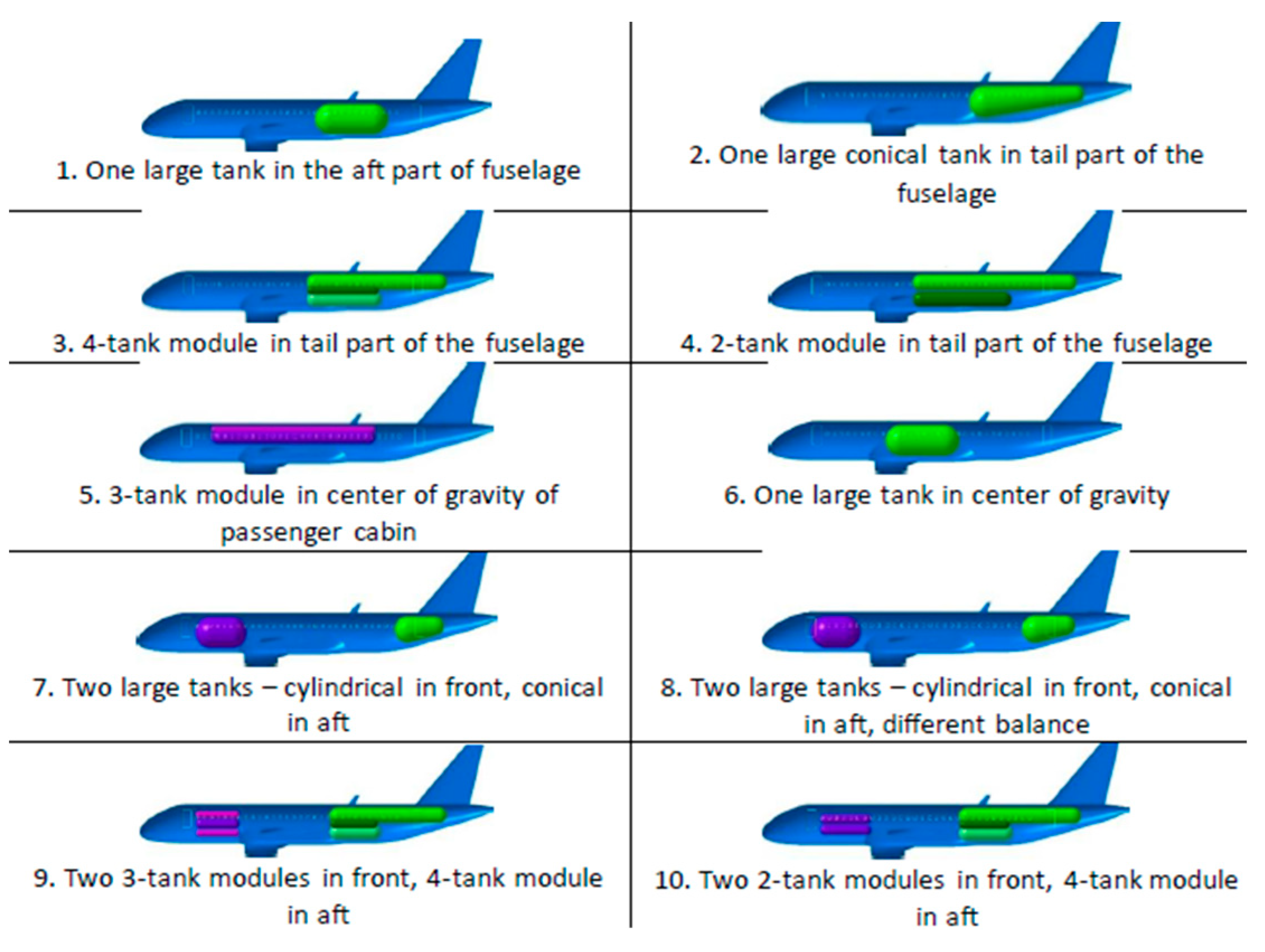
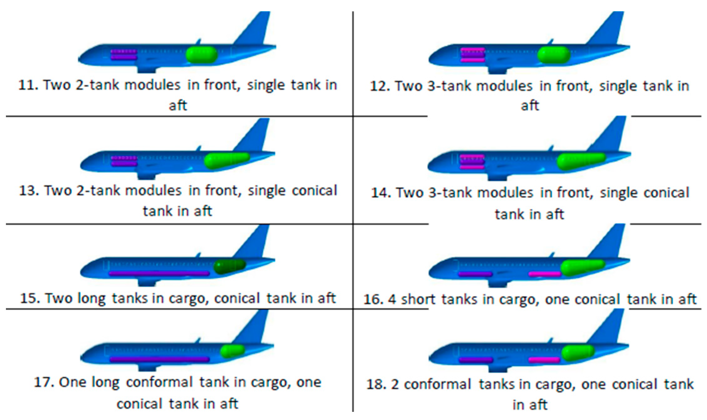
Multiple configurations combining these placement types were developed and are presented in
Figure 1. The main features included comparisons between large cylindrical or conical tanks and modules of smaller tanks in the aft part of the plane; one area (aft or front) and balanced distribution; and one large tank or tank modules with the walkway in the front part of the fuselage with partial fuel storage within the cargo bay. External drop tanks were considered to be impractical and were therefore not investigated further.
Multiple analyses were conducted to compare and evaluate the proposed concepts. The primary parameters considered were the total mass of the fuel system and aircraft, the system’s gravimetric index (GI), the achievable passenger capacity, and the aircraft’s center of gravity (CoG). In addition, range–payload trade-off analyses were performed for different fuel system volumes, reflecting the reduction in passenger capacity with increasing fuel requirements.
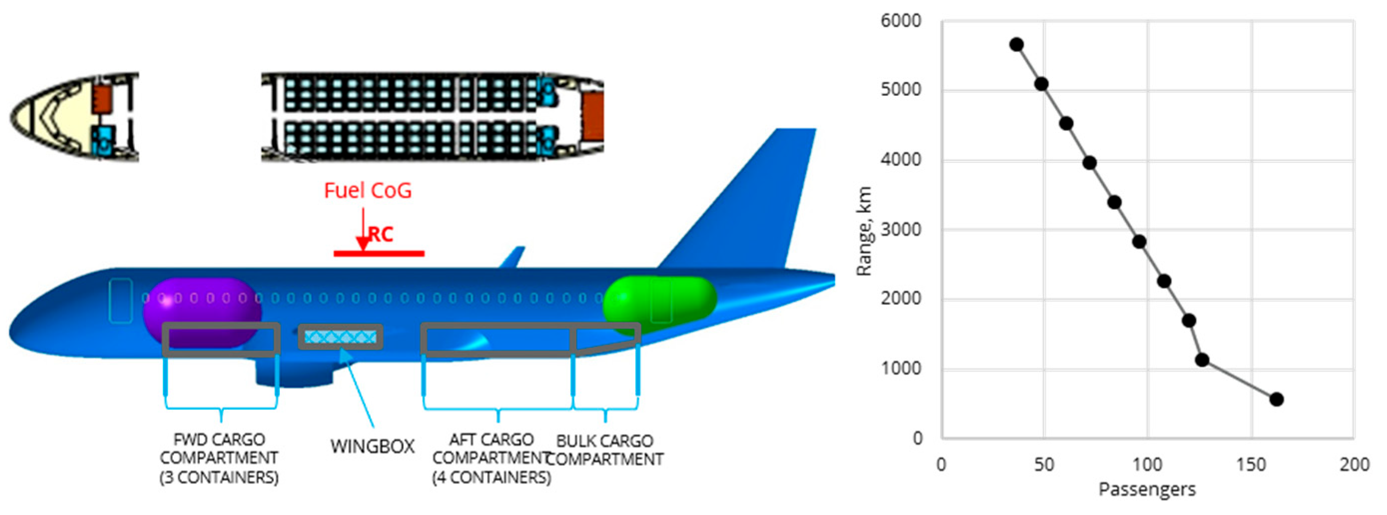
Figure 2 and
Figure 3 present examples of the results obtained.
Configurations incorporating one or two large tanks—labeled 1, 2, and 6–8 in
Figure 1—exhibit the most favorable performance in terms of both total system mass and gravimetric index (GI), with estimated fuel system masses between 6 and 7 t and GI values exceeding 0.45. All remaining configurations have estimated masses above 8 t and GI values below 0.4. The use of additional tanks necessitates extra subsystems and structural components, significantly increasing overall mass; consequently, configurations with fewer tanks consistently yield lower system weights. Owing to their relatively compact integration, these configurations also allow higher passenger capacities, typically between 80 and 120 passengers, depending on the specific layout. However, the highest passenger capacities (>120) are achieved in configurations 15–18, in which a portion of the fuel is stored in the cargo bay with the remainder located in the aft fuselage. In contrast, other combinations of modular tanks and large tanks require substantially more volume, limiting passenger capacity to fewer than 80 passengers.
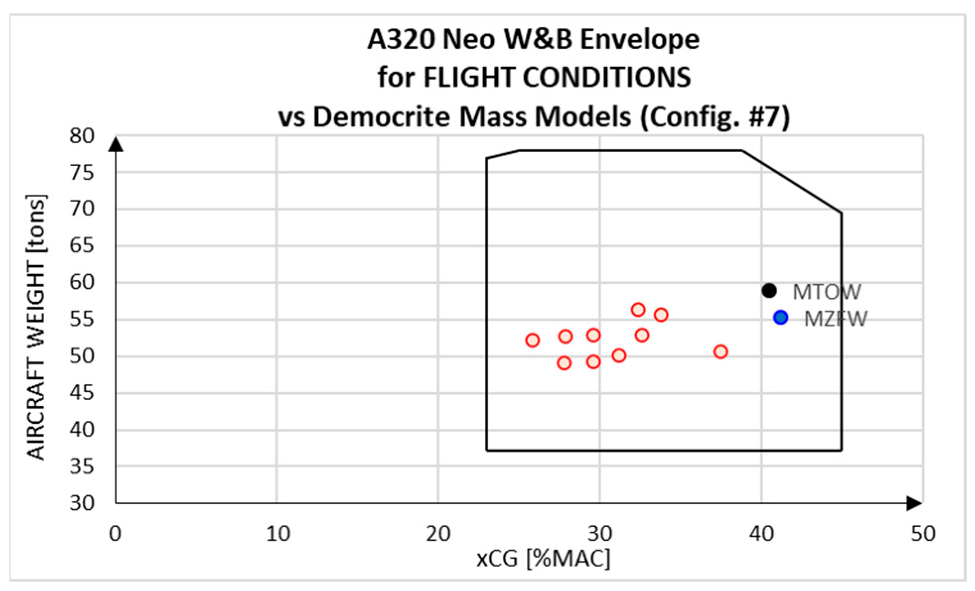
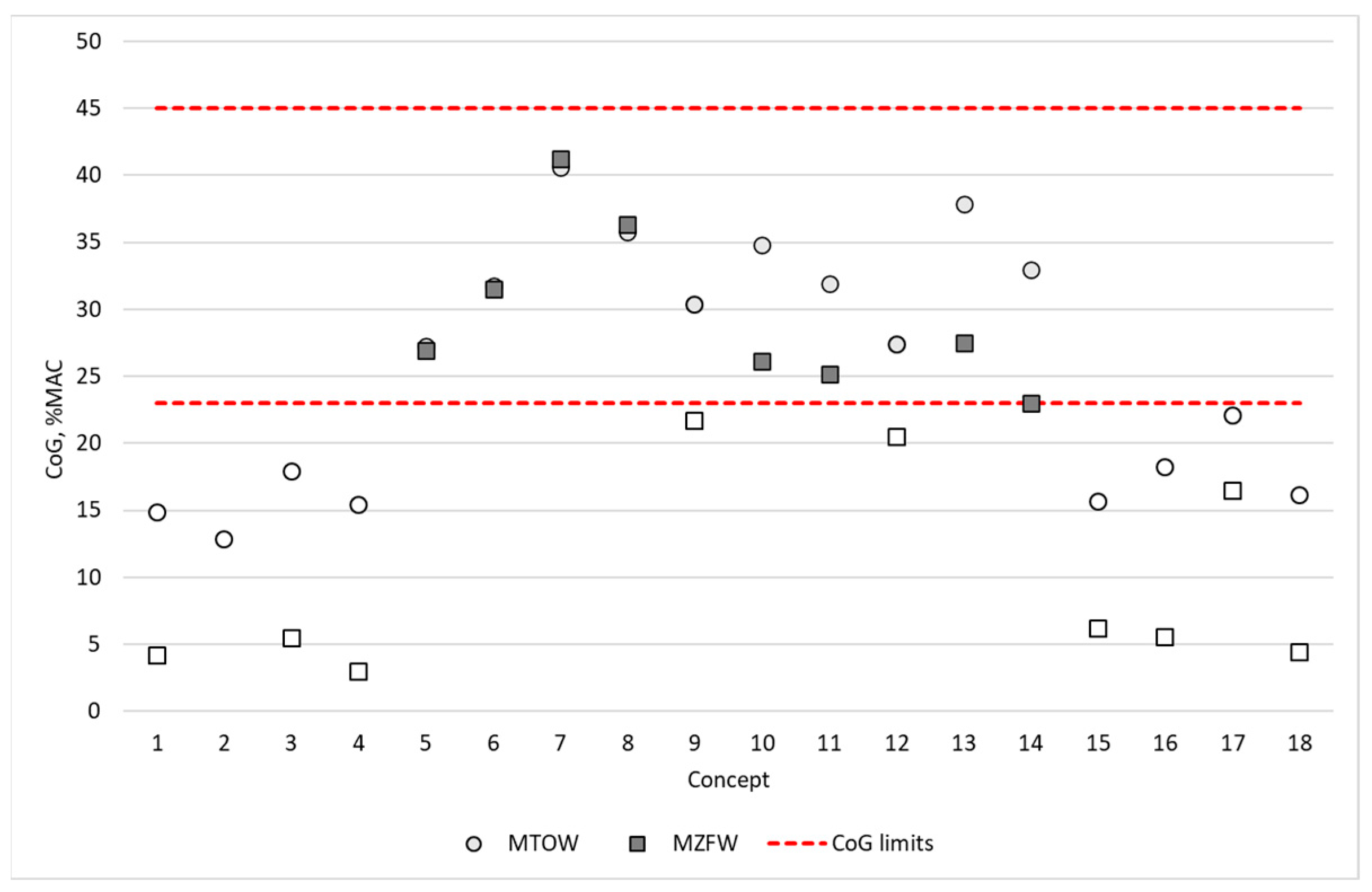
Finally, the aircraft’s center of gravity (CoG) was assessed. As the external aircraft geometry was assumed to remain unchanged, the allowable CoG limits of the existing A320neo were adopted. For each configuration, multiple load cases were evaluated, accounting for variations in passenger count and fuel quantity. A summary of these results is presented in
Figure 4. Two main conclusions can be drawn. First, under the assumption of unchanged overall dimensions, the total mass of a hydrogen-powered A320neo is reduced, primarily due to the low density of LH
2. Second, maintaining the CoG within operational limits requires either a configuration with a single tank or tank module located between the wings, or a configuration with fuel distributed between the forward and aft sections of the fuselage. In all other configurations—such as those with a single aft-mounted tank or fuel stored in the cargo bay—the CoG cannot be kept within allowable limits without the use of an active mass redistribution system.
3. Pressure Management of LH2 Tank Onboard Aircraft
The second task within the DEMOCRITE project was the safety analysis of proposed onboard liquid hydrogen storage systems. This approach consisted of reviewing existing standards from aviation and hydrogen industries to identify common practices and the key gaps to be bridged.
The general conclusion after surveying the main hydrogen and pressurized tanks regulations [
10,
11,
12,
13,
14] is that LH
2 tanks are, by definition, pressure vessels and should conform to applicable regulations. Since existing aircraft fuel tank regulations neither address the transport of LH
2 nor permit its carriage onboard aircraft, this represents a fundamental regulatory gap that must be addressed in future certification frameworks [
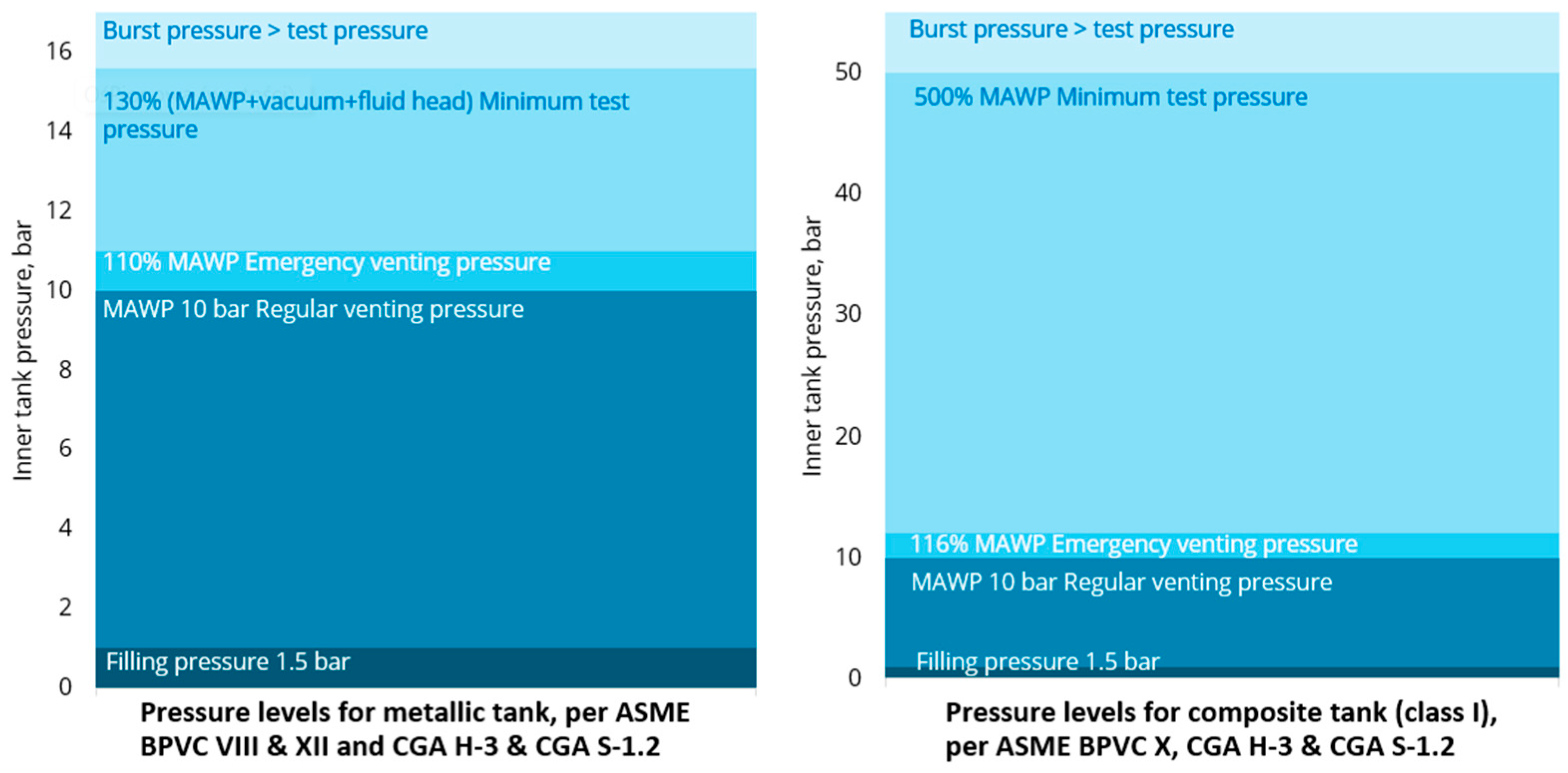
15]. A comparison of maximum allowable working pressures (MAWPs) and pressure requirements for LH
2 tanks designed according to current regulations is presented in
Figure 5.
After internal discussions, a filling pressure of 1.5 bar was assumed, while the MAWP of 10 bar was adopted from [
13]. The main difference between metallic and composite tanks is the test pressure required to withstand during the test. For metallic tanks, it is equal to 130% of the sum of MAWP, difference between insulation and outer pressure, and pressure due to weight of the fluid (fluid head)—in this case, combined to 15.5 bar. However, for composite tanks, this requirement corresponds to five times the MAWP, which is considered here to be the pressure at which standard pressure relief devices (PRDs) are opened. Emergency venting relies on the activation of additional PRDs under accident conditions. These devices are often of a non-reclosable type, such as burst disks; therefore, emergency venting will result in tank shut-off and the introduction of fuel system-wide safety means. As fuel transfer between cryogenic tanks is currently prohibited by regulations, an emergency-vented tank is effectively lost [
16]. As a result, the MAWP imposes fixed upper limit on pressure increases during both flight and refueling. The latter requires the connection of the tank to a venting stack to safely remove boiled-off gas [
17].
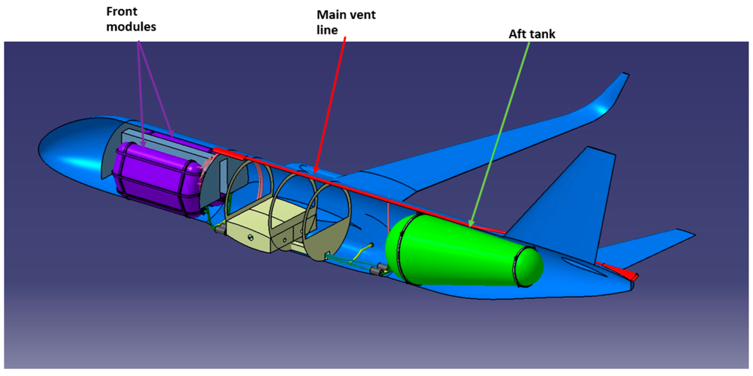
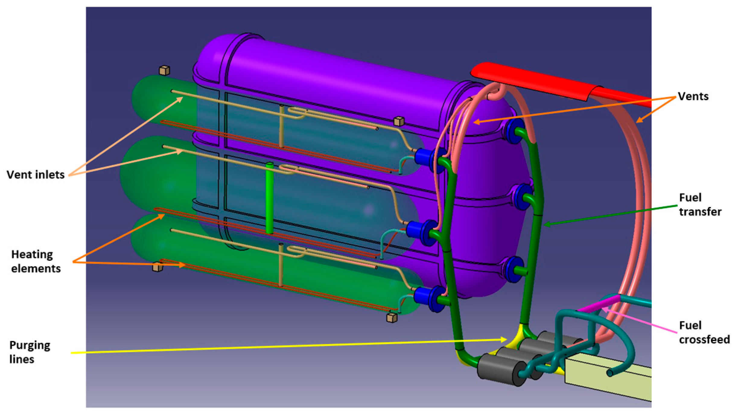
Figure 6 and
Figure 7 present models of onboard hydrogen venting systems as designed at this stage of the project.
In this model, each tank is equipped with two vents for both regular and emergency venting. All vent outlets are bundled together to a common venting line running on top of the aircraft. The common vent line ends at the tail cone to remove the gas away from the fuselage, with the assumption that the APU (auxiliary power unit) is replaced with fuel cell stacks. If this is not feasible, the vent outlet may be routed to the top of the vertical stabilizer in order to minimize fire risks associated with hot exhaust gases. Each tank is equipped with shut-off measures to prevent the failure of one tank from causing a pressure increase in the adjacent tanks.
Emergency venting and accelerated fuel disposal during flight pose significant challenge for LH
2 tanks. The disposal of LH
2 in uncontrolled environments is strictly prohibited by regulations; therefore, any fuel jettisoning would require evaporation of the hydrogen before venting [
18]. Two methods for accelerating this process were developed in this task: a pressurized helium purge and an accelerated boil-off. A pressurized helium purge was considered before in [
19]. According to this author, the mass of helium required for purging LH
2 increases linearly with hydrogen tank pressure. At a tank pressure of 10 bar, the extrapolated helium mass reaches about 30 kg per 100 kg of LH
2. If stored at 50 bar, this quantity of helium would require nearly 4 m
3 of space. Implementing this approach would require the installation of a high-pressure helium storage system onboard, introducing additional technological complexity and safety concerns. The other proposed method, an accelerated boil-off, would rely on internal heating elements increasing the hydrogen boil-off rate. The main drawbacks of this solution are the increased complexity in pressure management—particularly in smaller tanks, where a pressure rise would occur more rapidly—and a higher power consumption. Under emergency conditions, both factors could be detrimental, leaving the viability of this solution in question.
4. Conclusions
The initial work conducted within the DEMOCRITE project and presented in this paper has produced a substantial set of results and conclusions. Using A320neo and its geometry as a reference imposed fixed limits on fuel quantity and tanks dimensions, enabling the assessment of the effects of introducing LH2 into existing aircraft. The key conclusion was that single-location fuel storage has a highly detrimental effect on center-of-gravity management, rendering such configurations impractical within assumed limits. A front–aft distribution of the fuel system offers better stability, albeit with a passenger number trade-off.
Tank pressure management was addressed as a fundamental safety aspect of cryogenic fuel operation. As current aviation regulations do not address liquid hydrogen in any way, except for strict prohibition of its transport onboard, standards from the gas industry were adopted as a baseline for system development. A Fundamental difference was identified between metallic and composite tanks, with significantly higher strength requirements for the latter. Pressure management was envisaged through the use of dual pressure relief systems, comprising one device for normal operation and a second for emergency conditions. All vents would be connected to a common vent stack discharging outside the aircraft, enabling both safe hydrogen removal during in-flight emergencies and straightforward connection to ground venting infrastructure during refueling.
The results presented here represent only a portion of the work done by the DEMOCRITE project. More detailed safety analyses, sloshing and structural stress simulations, sensor considerations, and cryogenic test results will be reported in future publications.
Author Contributions
Conceptualization, M.K., C.J., M.B. and I.D.; methodology, literature, and calculations, M.K.; validation, M.B., C.J. and I.D.; writing—original draft preparation, M.K.; writing—review and editing, I.D.; supervision, I.D.; project administration, I.D.; funding acquisition, M.K., C.J., M.B. and I.D. All authors have read and agreed to the published version of the manuscript.
Funding
This research received no external funding.
Institutional Review Board Statement
Not applicable.
Informed Consent Statement
Not applicable.
Data Availability Statement
The datasets presented in this article are not readily available because multiple parties intellectual properties are involved in this research. Requests to access the datasets should be directed to corresponding authors.
Acknowledgments
M.K. would like to acknowledge the support of Ewa Marcinkiewicz, from Łukasiewicz Research Network—Institute of Aviation Aerodynamics Department, in center of gravity calculations.
Conflicts of Interest
The authors declare no conflict of interest.
Abbreviations
The following abbreviations are used in this manuscript:
| APU | Auxiliary Power Unit |
| CIRA | Italian Aerospace Research Centre |
| CoG | Center of Gravity |
| EREA | Association of European Research Establishments in Aviation |
| GI | Gravimetric Index |
| INCAS | National Institute for Aerospace Research “Elie Carafoli”, Romania |
| LH2 | Liquid Hydrogen |
| MAC | Mean Aerodynamic Chord |
| MAWP | Maximum Allowable Working Pressure |
| MTOW | Maximum Take-Off Weight |
| MZFW | Maximum Zero Fuel Weight |
| NACA | National Advisory Committee for Aeronautics |
| NASA | National Aeronautics and Space Administration |
| Nmi | Nautical Mile |
| PRD | Pressure Relief Device |
References
- Silverstein, A.; Hall, E.W. Liquid Hydrogen as a Jet Fuel for High-Altitude Aircraft; NACA Research Memorandum; NACA: Washington, DC, USA, 1955. [Google Scholar]
- Brewer, G.D.; Morris, R.E. Study of LH2 Fueled Subsonic Passenger Transport Aircraft; NASA Report CR-144935; NASA: Washington, DC, USA, 1976.
- Westenberger, A. Advances on Propulsion Technology for High-Speed Aircraft. In H2 Technology for Commercial Aircraf; NATO Science and Technology Organization: Neuilly-sur-Seine, France, 2008. [Google Scholar]
- ZEROe: Our Hydrogen-Powered Aircraft. Available online: https://www.airbus.com/en/innovation/energy-transition/hydrogen/zeroe (accessed on 13 November 2023).
- Zeroavia. Available online: https://zeroavia.com (accessed on 13 November 2023).
- Universal Hydrogen. Available online: https://hydrogen.aero/ (accessed on 13 November 2023).
- Hydrogen-Powered Aviation. A Fact-Based Study of Hydrogen Technology, Economics, and Climate Impact by 2050, McKinsey & Company for the Clean Sky 2 JU and Fuel Cells and Hydrogen 2 JU, Luxembourg. 2020. Available online: https://www.euractiv.com/content/uploads/sites/2/2020/06/20200507_Hydrogen-Powered-Aviation-report_FINAL-web-ID-8706035.pdf (accessed on 13 November 2023).
- Airbus 320neo Family. Available online: https://en.wikipedia.org/wiki/Airbus_A320neo_family (accessed on 12 October 2023).
- A320 the Most Successful Aircraft Family Ever. Available online: https://aircraft.airbus.com/en/aircraft/a320-the-most-successful-aircraft-family-ever/a320neo (accessed on 12 October 2023).
- ASME Boiler and Pressure Vessel Code Section VIII–Rules for Construction of Pressure Vessels, 2023rd ed.; The American Society of Mechanical Engineers: New York, NY, USA, 2023.
- ASME Boiler and Pressure Vessel Code Section X–Fiber-Reinforced Plastic Pressure Vessels, 2023rd ed.; The American Society of Mechanical Engineers: New York, NY, USA, 2023.
- ASME Boiler and Pressure Vessel Code Section XII–Rules for Construction and Continued Service of Transport Tanks, 2023rd ed.; The American Society of Mechanical Engineers: New York, NY, USA, 2023.
- CGA H-3: Standard for Cryogenic Hydrogen Storage, 4th ed.; Compressed Gas Association: McLean, VA, USA, 2024.
- CGA S-1.2: Pressure Relief Device Standards-Part 2-Portable Containers for Compressed Gases, 11th ed.; Compressed Gas Association: McLean, VA, USA, 2024.
- 49 CFR 172.101 Purpose and Use of the Hazardous Materials Table. Available online: https://www.ecfr.gov/current/title-49/subtitle-B/chapter-I/subchapter-C/part-172/subpart-B/section-172.101 (accessed on 15 November 2024).
- 49 CFR 173.301 General Requirements for Shipment of Compressed Gases and Other Hazardous Materials in Cylinders, UN Pressure Receptacles, and Spherical Pressure Vessels. Available online: https://www.ecfr.gov/current/title-49/subtitle-B/chapter-I/subchapter-C/part-173/subpart-G/section-173.301 (accessed on 15 November 2024).
- EIGA Document 06/19, Safety in Storage, Handling and Distribution of Liquid Hydrogen; European Industrial Gases Association: Brussels, Belgium, 2019.
- CGA G-5.5, Standard for Hydrogen Vent Systems, 4th ed.; Compressed Gas Association: McLean, VA, USA, 2021.
- Johnson, W.R. H2 Technology for Commercial Aircraft. In Helium Pressurant Requirements for Liquid-Hydrogen Expulsion Using Submerged Gas Injection, TN D-4102; NASA: Washington, DC, USA, 1967. [Google Scholar]
| Disclaimer/Publisher’s Note: The statements, opinions and data contained in all publications are solely those of the individual author(s) and contributor(s) and not of MDPI and/or the editor(s). MDPI and/or the editor(s) disclaim responsibility for any injury to people or property resulting from any ideas, methods, instructions or products referred to in the content. |