1. Introduction
The life cycle assessment here described aims to evaluate for the HERFUSE project [
1] the potential environmental benefits achievable by the implementation of a set of innovative solutions proposed in the framework of the HORIZON Europe programme [
2]. Two commercial concepts have been considered as new Hybrid-Electric Regional Aircraft (HERA) [
3]: the Use-Case B (UCB) and the Ultra-Efficient Regional Aircraft (UERA) concepts. The first one (UCB) is an innovative long-term target with a planned entry in service (EIS) in 2050 and is devoted to developing a distributed propulsion architecture by means of three engines per semi-wing with one hybrid powerplant and two electric engines. The electric motors are fed by fuel cell systems using liquid hydrogen as energy source. The UERA concept, on the other hand, is equipped with two parallel hybrid power-plants (based on batteries) under the two semi-wings; on each semi-wing, the thermal engine is coupled with an electric engine at the technological maturation level available for a 2035 EIS. At the same time, to support the estimation of the achievable benefits, an existing regional turboprop aircraft has been selected and adopted for comparison purposes. This aircraft model is the ATR 72-600 [
4] representative of the technology state of the art in 2020 and characterized by a similar functionality and category commonality. Firstly, effort has been devoted to defining an LCA [
5] approach, based on ISO Standards [
6,
7], suitable to identify and describe the relevant innovations elaborated in HERFUSE for HERA concepts in the frame of the CA initiatives [
8,
9]. Nowadays, it is mandatory to assess the environmental impact of innovative technologies, and in the HERFUSE project, this has been grounded on globally accepted methodologies and on holistic scientific models and applicable data inventories. The goal of the performed activity is to deliver a life cycle assessment of the innovative solutions of the HER [
10] fuselage and empennages; in this view, all the investigated disruptive structural technologies and related industrial processes suitable for reducing the fuselage and empennage weights, reducing the related flight fuel consumption, contributing to global warming mitigation, and preventing the deterioration of air quality in terminal airport areas, have been properly addressed.
2. LCA Approach
The LCA is a science-based approach able to evaluate the potential environmental impacts as well as the market development and cost analysis. In this case, the LCA is focused on the environmental impacts due to the proposed innovations for the structural parts of the fuselage and the empennages, taking into account also the integration of the secondary structures necessary for the onboard installation of legacy and new systems identified in HERA in relation to the proposed solutions: technologies, configurational concepts, materials, and industrial processes, as well as the operations and services.
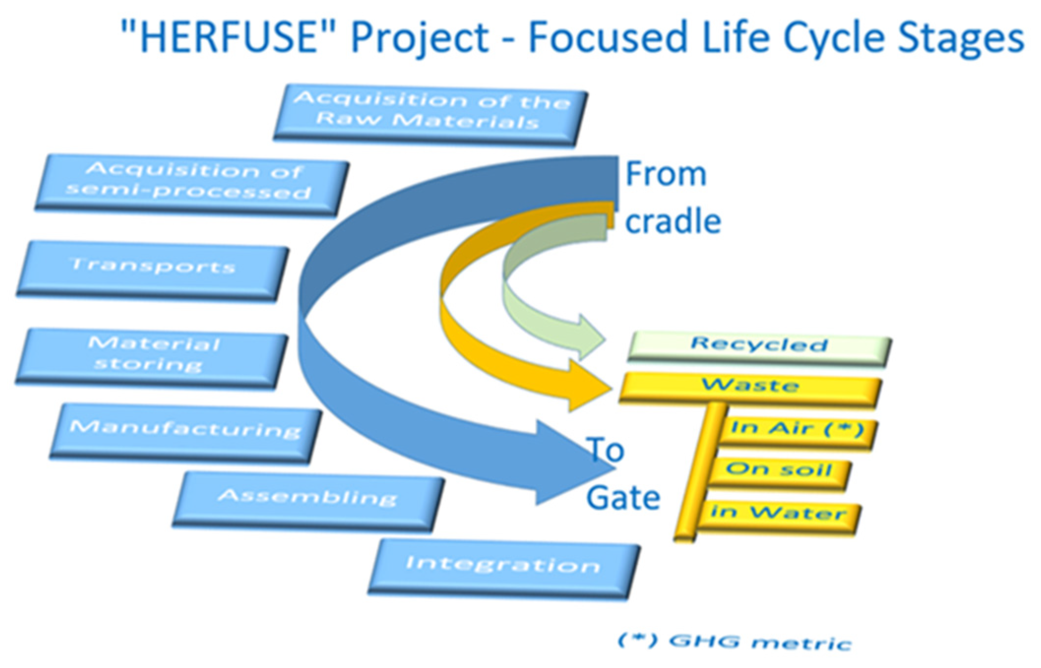
The LCA methodology consists of carrying out an assessment of used natural resources, used raw materials and semifinished ones, energy consumption from the national electrical grid and burned fuels and the related emissions in air, water, and on the ground, for the life cycle stages of interest for a specific system from Cradle-to-Gate (C2G).
The Cradle-to-Gate approach, which involves the assessment of a product life cycle from the raw material extraction (‘cradle’) and manufacture to the factory exit gate, including the use and end-of-life phases, has required interactions with the technology owners involved in HERFUSE project, also involving stakeholders from the other synergic/daring projects linked to the coordinated HERA initiative. Moreover, the LCA methodology allows for the comparison of different scenarios and the identification of pollution transfers (so-called “burden shifting”) from one type of impact on the natural environment to another, or from one life cycle stage to another, between two different scenarios of the same system, or between two different systems. Thus, LCA can be used in the context of a “design for the environment” approach or for supporting the decision-making process.
Figure 1 shows the life cycle stages of interest for the HERFUSE project.
The approach has been based on the guidelines reported in ISO standard 14040:2006 (Environmental Management—life cycle assessment—Principles and Framework) [
6]. and ISO 14044:2018 (Environmental Management—life cycle assessment—Requirements and guidelines) [
7].
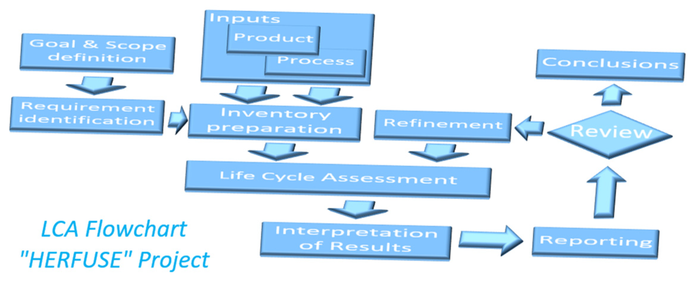
Figure 2 shows the reference assessment steps considered and related sequence.
First, all incoming and outgoing flows (material and energy flows, both extracted from the environment and released into it) are inventoried for each life cycle phase. Then, they are aggregated to quantify with different possible methodologies (e.g., IPCC GTP100 [
11], Environmental Footprint 3.1 (EF3.1) [
12]) with an adapted version of the commercial SimaPro tool (Copyright © 2025 PRé Sustainability). At the same time, specific data sets have been used like, e.g., Ecoinvent 3 [
13], Industry data 2.0 [
14]. The typical environmental impacted categories are: GTP100-Fossil, -Biogenic and -Land transformation expressed in terms of kg CO
2eq, while the impact characterization with EF3.1 has been done referring to the impact categories: Acidification; Climate change; Ecotoxicity; Particulate matter; Eutrophication (marine, freshwater and terrestrial); Human toxicity; Ionizing radiation; Land use; Ozone depletion; and Resource use.
3. Product Description
The analysis has been done adopting a product tree structure suitable to trace and cumulate all contributions due to the proposed technologies and adopted industrial processes. This detailed analysis covers all fuselage segments (Forward, Centre and Rear) and empennage units (Vertical and horizontal tail surfaces) as well as the related panel demonstrators, e.g., Vertical Tail Box, Fuselage Upper Shell, Fuselage Lower Shell and Fuselage Lateral panel. The HERFUSE project, focused on Hybrid-Electric Regional Aircraft (HERA), collects the effort of many European aeronautical industries as well as top-level providers. Their coordinated actions aim to develop and validate a set of innovative key technologies able to support the entry in service (2035 and 2050) of new civil regional aircraft able to mitigate the environmental impact of the aviation sector. Referring to the UERA concept, the proposed key technologies have been the development of a vertical empennage box by means of co-cured and bounded multi-ribs; composite thermoset-floor beams by means of fully automatic press moulding and fast-curing process; windows made with fibre patch placement and structural fittings made with recycled-thermoplastic materials. On the other hand, for the UCB concept, the main key technologies have been: the adoption of Liquid Resin Infusion (LRI) and hot-press forming to create fuselage structural panels in a single monobloc; and testing and validation of new materials and solutions to prevent fuselage damage due to, e.g., projected ice shards. New combinations of composite materials (CFRP-TS, CFRP-TP) and assembly methodologies, e.g., by means of conductive and resistance welding, guarantee a lower footprint and several manufacturing advantages like, at least, the reduction in the number of rivets used. Metal-composite parts are made with lighter aluminum alloys and using new bonding processes or additive manufacturing.
The previously mentioned innovative solutions are elements of a vast group of main relevant enablers able to support, with an optimized design of innovative fuselage, the adoption of advanced composite technologies, new materials, new manufacturing processes with new light tooling needs, and strongly integrated assembling processes.
In this LCA activity, the following steps have been adopted:
To identify the system boundaries referring to the LCA tasks.
To create an in-house parametric model devoted to describing with a single common analytic structure the architectural configuration of the HERA-UCB and UERA concepts as well as the regional turboprop considered as a baseline for comparison.
To consider the planned activities related to the design and build-up of a set of demonstrators in support of the validation tasks.
Table 1 shows the boundaries of the LCA System considered.
Considering that the design of the different parts is still in progress as well as the definition of the focused processes, an analytic description of the LCA model has been developed for quicker inclusion of new items, ensuring the coverage of all affected structural parts, ensuring new requested changes, and keeping track of the different versions generated during the HERFUSE project phases (e.g., 2nd Interim UCB). Another analytic model has also been created to identify the existing relationships among the panel parts of the demonstrators and the related fuselage and empennage ones to support the scaling of the environmental results of the demonstrators to the full-scale aircraft for each main part, e.g., Forward fuselage, Centre fuselage, etc. These relative weight relationships enable the evaluation of technology impacts relevance at the fuselage and empennage level, starting from the potential benefits validated at the demonstrator level by means of ground testing and the monitoring of the processes.
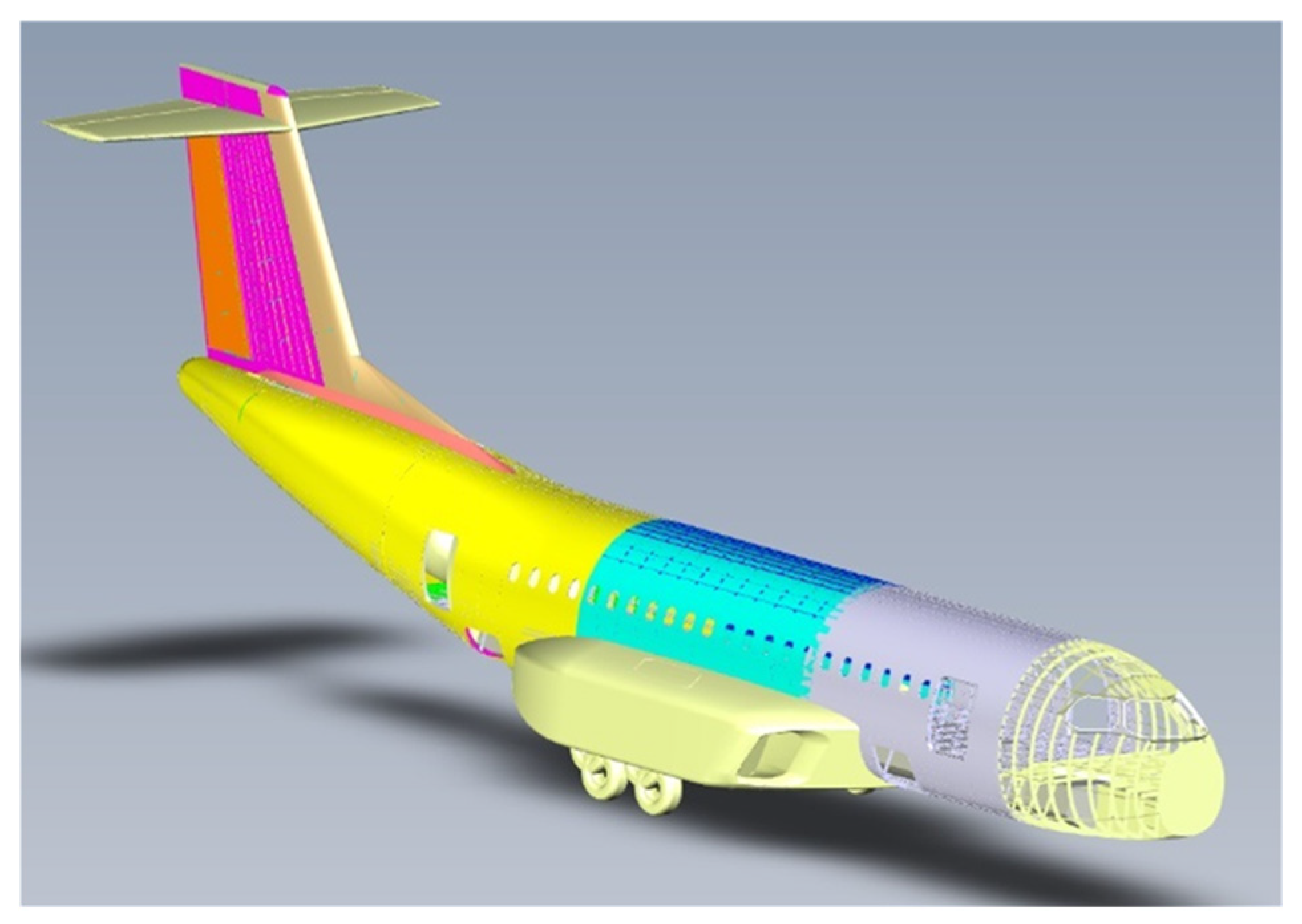
The structural parts of interest of the fuselage for the UCB and UERA concepts have been the cockpit and the cabin fuselage portions: forward segment, centre segment, rear segment and the cone apex, while the main empennage units of interest are the vertical tail unit and the horizontal ones (
Figure 3). Another relevant subject under analysis is HER Systems integration. Starting with the mass budgets and inputs provided by HERFUSE Partners, a related bill of materials (BoM) has been developed for each concept.
4. Transport Network
One important contribution to environmental emissions related to any product is associated with the transport activities of the manufactured parts as well as the used raw and/or semifinished materials through all production steps of the facilities involved.
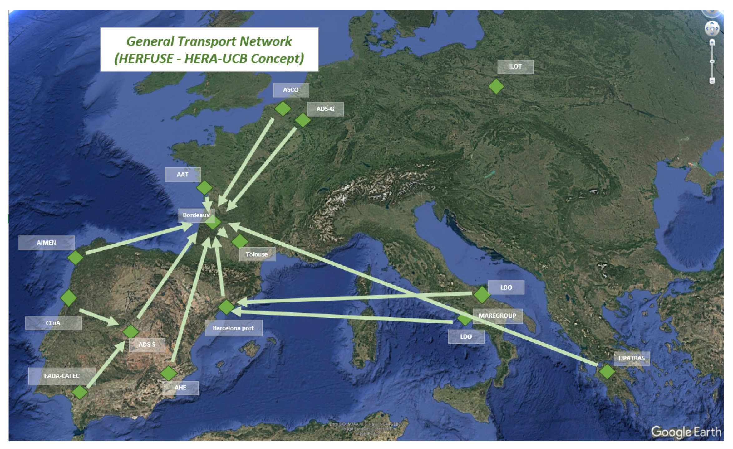
The transport network related to the concepts at high level includes external and internal transport trips both at national and international level. This transport characterization has been done for the main fuselages and empennage components among the facilities, including the contributions due to the transport of the semifinished components or ancillaries, considering the geographical distribution of the involved main actors.
Figure 4 shows the general transport network considered for the UCB concept.
This transport description has been based on the following parameters: “Transport segment”, “Assumption”, “Segment type”, “Transport type”, “Transported payload”, “Used fuel”, “Estimated Payload weight [kg]”, “Distance [km]”, “Transport metric unit [tonnes*km] (tkm)”, “Speed”, “Trip time [h]”, Data source reference” as well as publicly available organization address.
5. Process Flowchart
Based on the shared information related to the manufacturing processes, preliminary schemes of the flow of masses through the considered industrial stages have been developed as a first loop of the assessment step.
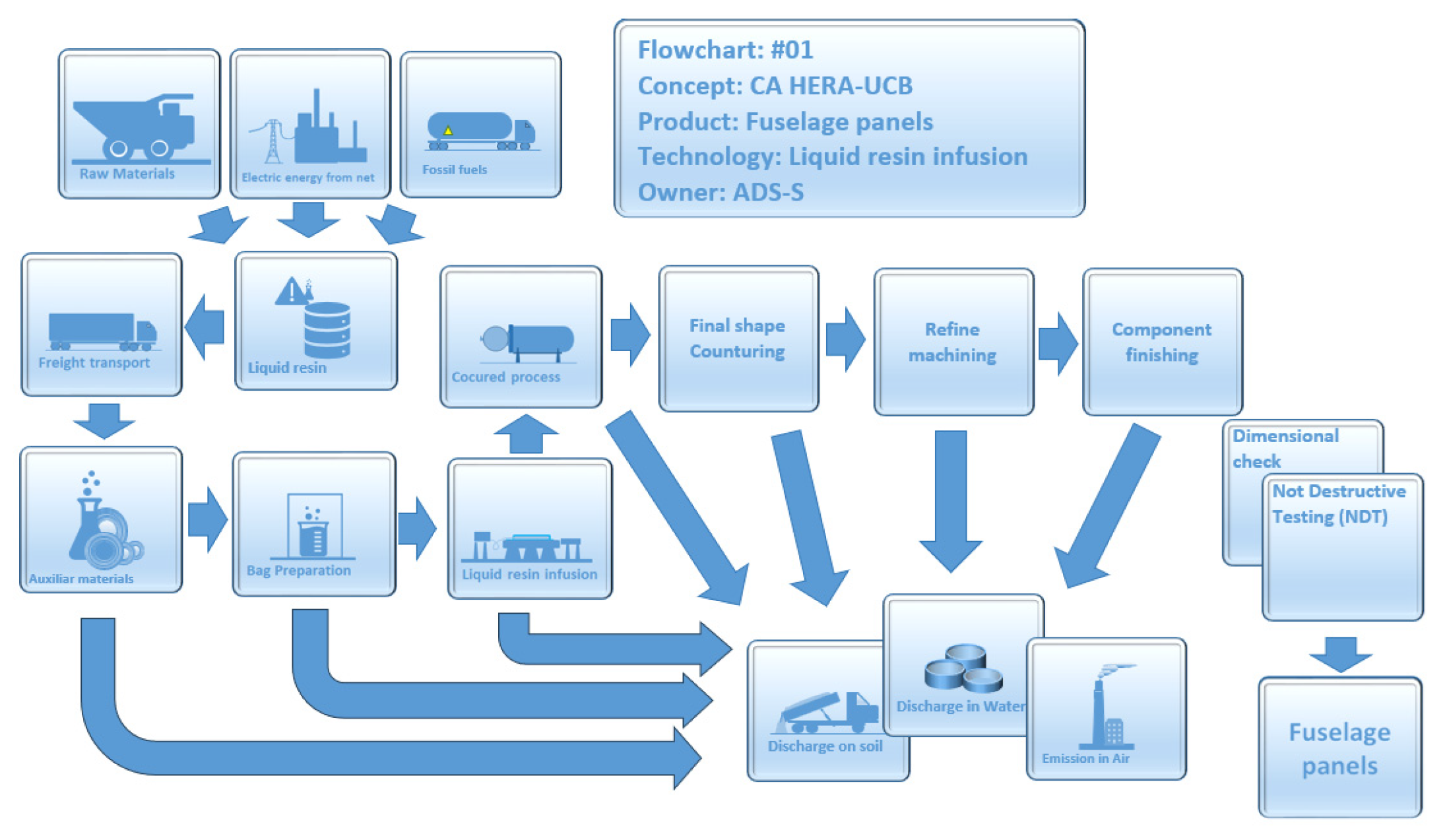
Figure 5 shows the considered reference flowchart related to the Fuselage Lateral panel manufacture by means of Liquid Resin Infusion (LRI).
6. Results and Next Steps
The relative weight of the structural parts has been calculated to support the benefits evaluation at fuselage level, considering the relevance of the aircraft parts and in relation to the actual available information/data on the proposed processes. A huge number of fittings are generally used to block payload boxes, electrical harnesses and other small components with the primary structural parts of the aircraft.
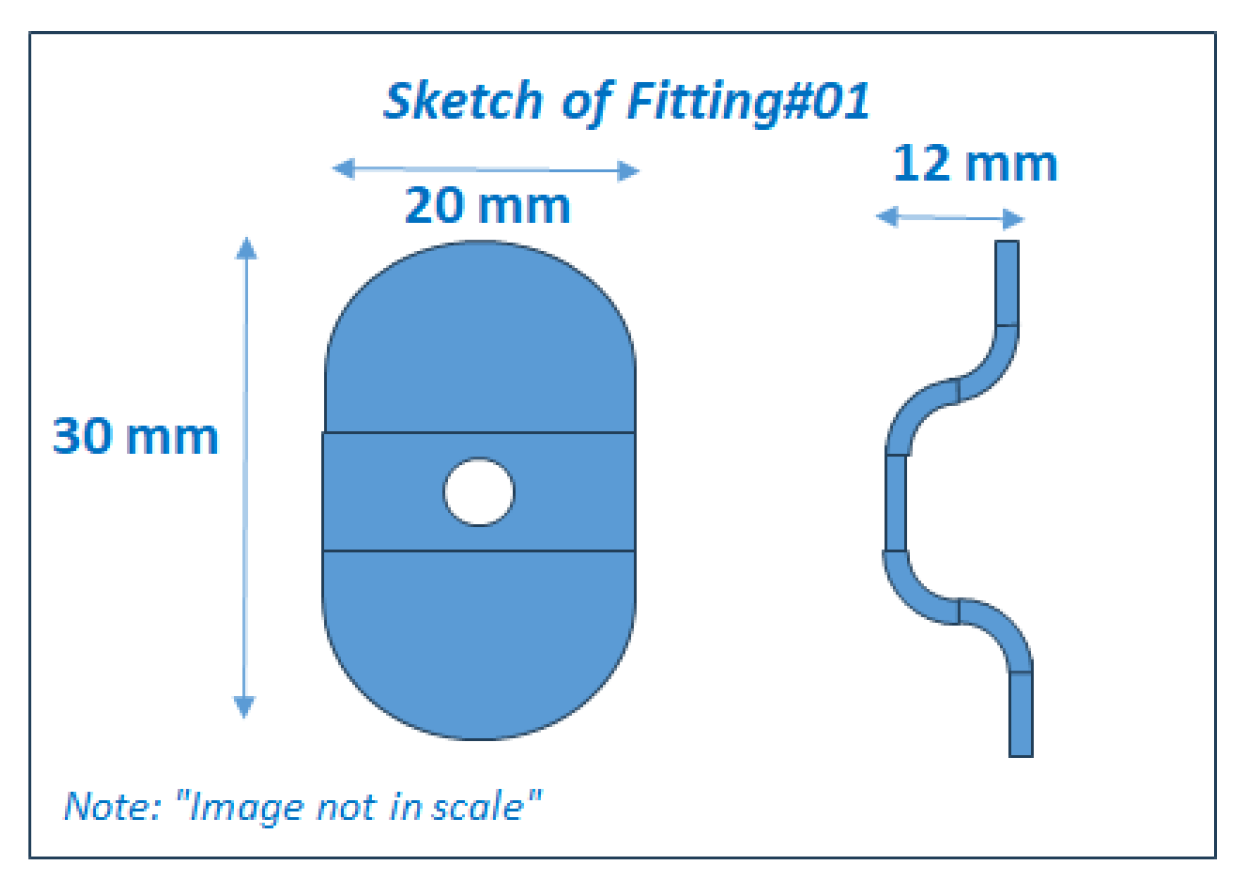
Figure 6 shows the assessed fitting adopted as representative of this group of items.
Table 2 reports the preliminary environmental impacts calculated using the SimaPro tool and the reported assumptions.
The potential impact reduction in terms of kg CO2eq appears very impressive for the structural fittings if they are made by injection moulding using CFRP-TP instead of aluminum alloy. The impact evaluation has been performed adopting as input the “Metal working, average for aluminum product manufacturing {GLO}| market for | APOS, S” and the “Aluminum removed by milling, small parts {GLO}| market for | APOS, S “process at global worldwide level. The calculated preliminary benefit appears very large −6088.9 kg CO2eq (−89.7%), while it is −84.2% in case of virgin carbon fibre with 1069.5 kg CO2eq. In this light, the manufacturing of a very large number of metal fittings by means of the CNC milling process appears very expensive.
To emphasize the complexity affecting the evaluation of the environmental impacts for the aircraft parts, a second example has been hereafter reported that is related to composite thermosetting floor beams made with a fast-curing resin thermoforming process.
Table 3 shows the preliminary calculated impact referring to UERA and the baseline concept.
The environmental impact for the floor beam in CFRP-TS is larger than the metallic case (“Metal working, average for aluminum product manufacturing {GLO}| market for | APOS, S”) with a contribution due to impact extrusion step. A large part of this impact is due to the carbon fibre of 2399.1 kg CO2eq (81.7%). These are, of course, preliminary outputs. Deeper analyses are necessary to identify effective and shareable assumptions related to a more detailed description of the processes based on direct measures performed during the manufacturing process as well as to integrate new material and process cards into the datasets to support robust impact results.
The next steps will be devoted to integrating new process information and to extending the material and process description with new dataset cards suitable for updating the LCA model considering the manufacturing cycle refinements and new bill of materials related to the proposed concepts. Moreover, a sensitivity analysis will be performed in relation to the data uncertainties with the identification of possible recycling opportunities, supporting the impact monitoring and the final loop assessment.



 ,
,