1. Introduction
The electrification of aircraft is a central focus in current aerospace development [
1], spanning electrified subsystems (e.g., rudder control and door actuators), electrically powered small aircraft such as eVTOL, and concepts for hybrid and fully electric propulsion in larger aircraft. Across these applications, there is a need for battery systems that meet two primary requirements: high safety and high energy density [
2]. While lithium-ion battery cell technology has achieved great advances, only a combination with a suitable battery housing allows safe operation. Current airworthy battery pack housings (like Saft AirLion™ or true blue power TB14) are often made of steel or aluminium to mitigate the risks associated with thermal runaway (TR) in battery cells. In this paper—the first of its kind—a lightweight battery housing based on phenolic resin composites is investigated for its resistance to battery fire.
1.1. Thermal Runaway and Thermal Propagation
Thermal runaway (TR) in a battery cell denotes a rapid, destructive event in which local temperature elevations or electrical or mechanical damage lead to the failure of the cell, resulting in internal short circuits between anode and cathode and the release of additional heat [
3]. Prior to and during TR, cells eject large quantities of highly flammable venting gases and particles [
4,
5]. Thermal propagation (TP) occurs when TR in one cell initiates the TR in a neighboring cell. Propagation can be driven by conductive heat transfer between adjacent cells, as well as by heat carried in potentially combusting vented gases [
6,
7]. Gas pressure, particles, and elevated temperatures represent the load cases acting on the battery housing during a TR event, and the housing must be designed accordingly to withstand these conditions.
1.2. General Housing Design
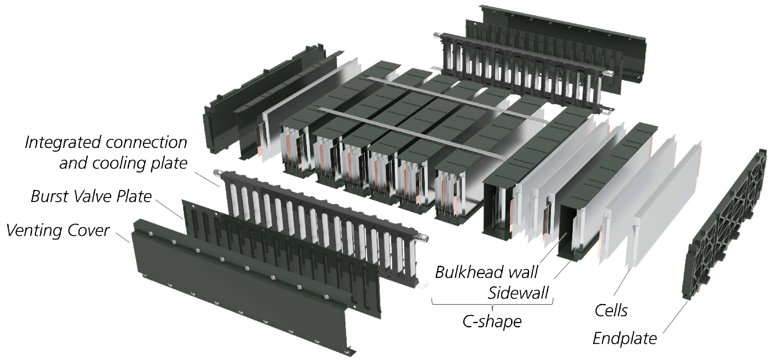
In previous work, the design of the composite housing, which was derived from an analysis of a typical Li-ion pouch cell, was presented [
8] and is shown in
Figure 1. The phenolic material Vyncolit X655FR was selected for most housing components, as it offers suitable manufacturability (injection molding, injection–compression molding, or compression molding) together with promising thermal capabilities at elevated temperatures. As a thermoset-based material with a high content of glass fibers and mineral fillers (together comprising 80%), it neither melts nor burns away, but forms a ceramic-like structure (as shown in the white areas in
Figure 2c and
Figure 3a). The housing components leverage the constraints and advantages of mold-based polymer processing. Groups of four (or two) stacked cells are separated by bulkheads in “C-shaped” housing parts, which additionally include cell fixture and sidewall elements. This approach of a thermal propagation hindering layer was chosen because it was more simple and potentially cost-effective compared to aerogel [
9,
10] or phase change separators [
11]. While the “C-shape” encloses the cells on four sides, the remaining openings are covered by burst valves, which are part of an integrated connection and cooling plate. This arrangement aims to combine selected benefits of pouch and prismatic cells.
This paper evaluates, through targeted testing, the features of the composite battery housing that are relevant to fire protection. The bulkheads (the central wall section of the C-shape) are examined with respect to TP times between adjacent cells. Sidewalls (the lateral wall sections of the C-shape) are assessed for their ability to prevent uncontrolled gas and flame propagation. The burst valve is investigated regarding its capability to open a controlled relief path for venting gases while shielding the remaining cells from exposure.
In general, the performance of a pack housing against the effects of TR is assessed via abuse testing at the pack level. The component-level tests in this paper are designed to bridge the gap between material-level characterization and full-module or pack testing.
2. Component-Level Tests
Component-level tests provide early insight into the behaviour of complex parts under relevant TR scenarios, without requiring more elaborate experiments that use real battery cells. This approach is of particular interest because, with the broader use of polymer-based, composite materials in the battery housing, the number of possible material combinations and processing treatments increases substantially compared to full metal housings. Component-level tests therefore offer a means to screen and evaluate new design concepts more rapidly using relevant, targeted measurements.
2.1. Compartment Torch Test
To evaluate the behaviour of the compartment design, a component-level torch test was conducted. As the stacked C-shape parts constitute the primary fire protection layer of the battery, the test addresses the following questions: How does the complex geometry of the thin-walled part influence the overall response, such as the occurrence of cracks, substantial deformation, or self-ignition? How does the interaction of multiple parts perform, particularly at the labyrinth seal that is also filled with silicone? Can the heat transfer through the bulkhead wall, and thus the propagation time, be estimated?
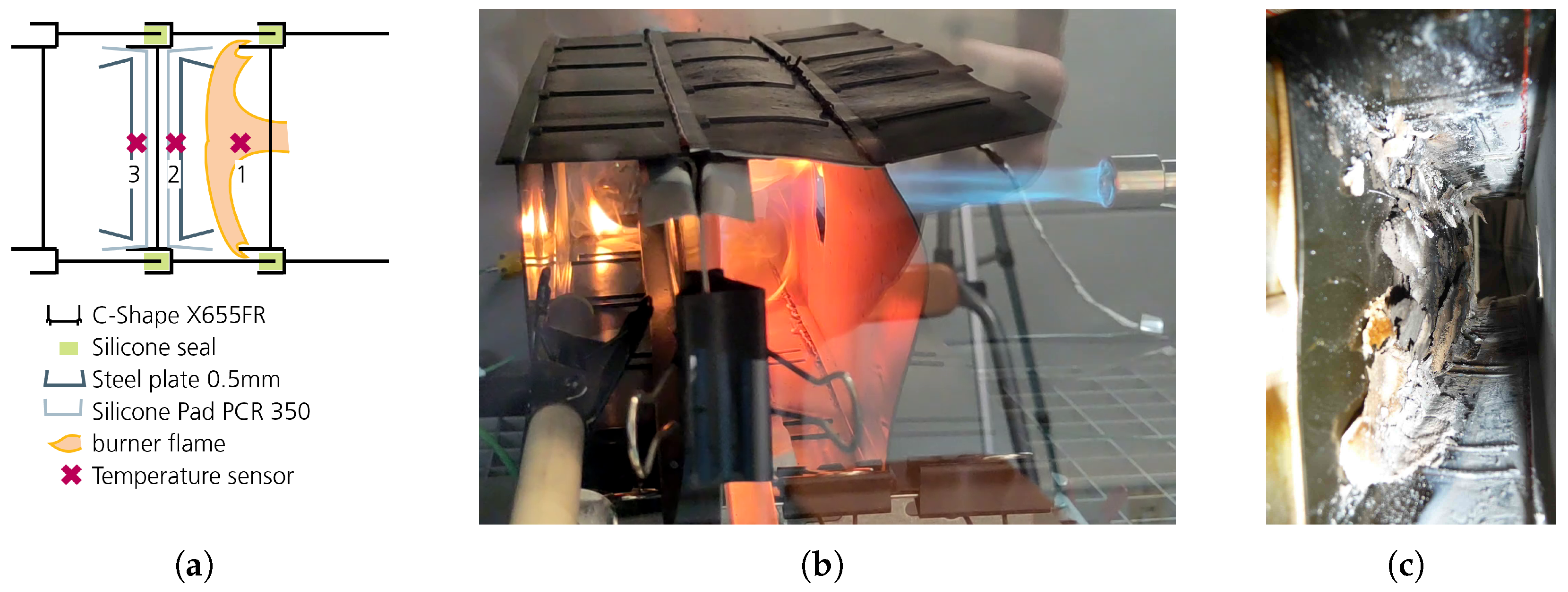
The test configuration consists of three C-shaped compartments that form two semi-closed chambers. The primary chamber is heated by a blowtorch through a hole in the corresponding wall. The bulkhead wall separating the two chambers is equipped with compression pads (2 × 1 mm silicone foam pad, PCR350) and steel plates (0.5 mm), with the steel plates representing the cell surface. Temperatures are measured in the flame and on the steel sheets representing the primary and secondary cell surfaces.
Two test runs were performed. The blowtorch (probe 1), operated at approximately 1180 °C and 800 °C, was used to heat the primary cell dummy to 1000 °C and 600 °C, respectively, representing possible thermal runaway cell temperatures (probe 2).
The secondary dummy cells (probe 3) reached peak temperatures of 782 °C and 445 °C in the 1000 °C and 600 °C tests, respectively. A temperature of 300 °C, which was considered a possible trigger for thermal propagation, was recorded after 135 s in the 1000 °C test and after 254 s in the 600 °C test.
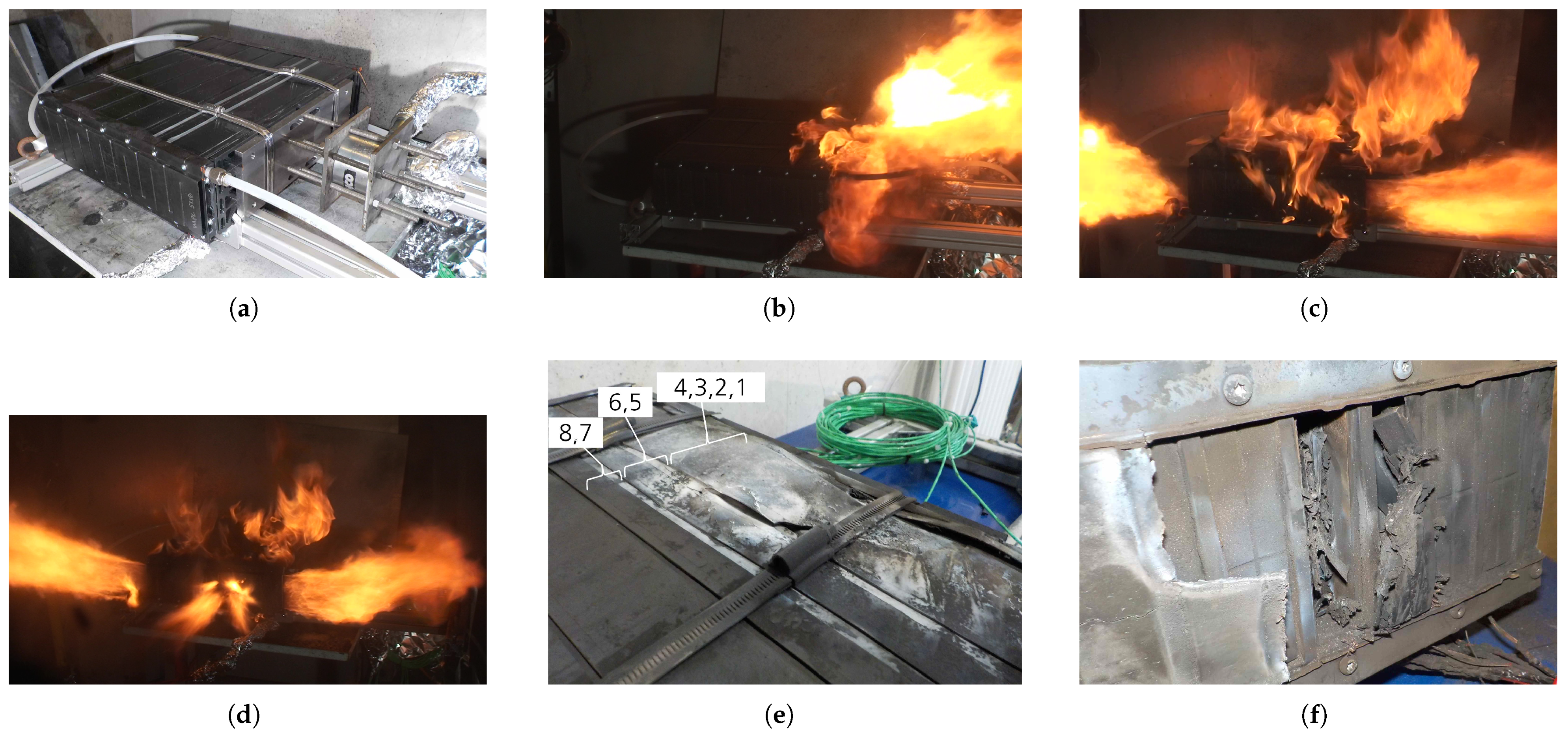
With respect to structural behaviour, bending of the sidewalls was observed; however, no cracks were detected, as shown in
Figure 2c. The exterior surfaces of the sidewalls did not ignite, although brief flame egress was observed from the gap between the cell dummy sheets. At 366 s, the labyrinth seal failed at a location in the lower area, offset from the torch burner, resulting in a flame of approximately 1 cm inside the secondary compartment, as can be seen in
Figure 2b. This flame self-extinguished after a further 195 s. Minor surface bubbling was identified, and areas exposed to the highest heat exhibited surface whitening.
2.2. Sidewall Particle Resistance
The sidewalls of the C-shape must withstand and redirect gases that may escape from the side of a cell. Therefore, a test specimen was subjected to a torch-and-grit test. The specimen consisted of two connected sidewalls cut from the assembly, with portions of the bulkhead wall still attached. This configuration was chosen to capture geometric influences. During the test, a localized area on one sidewall was heated with a 1300 °C blowtorch flame and subsequently blasted with sand-grain particles (2.5 g cm−3).
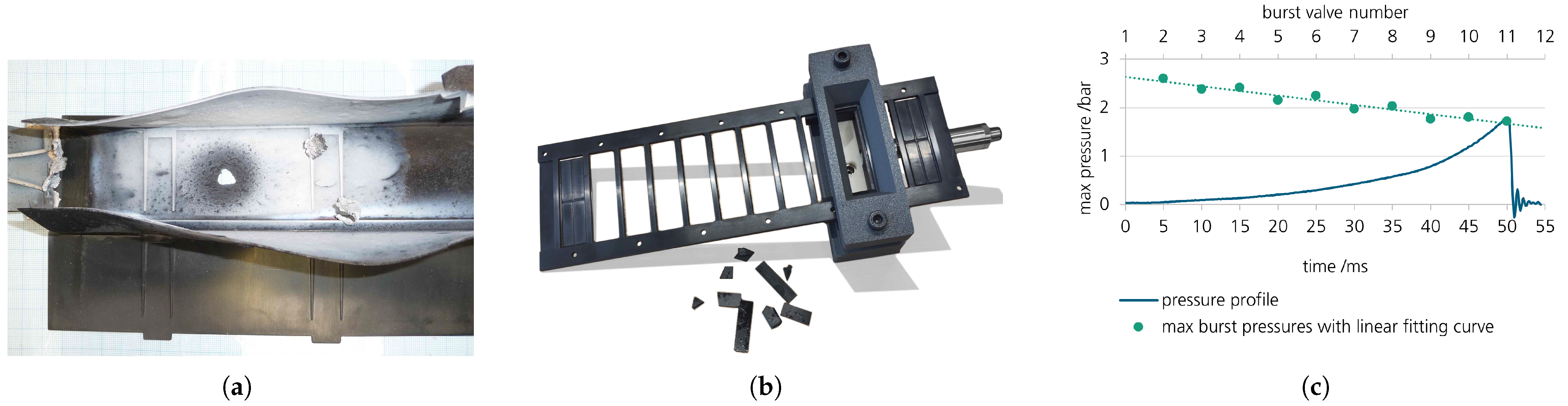
During testing, the sand particles were deflected back into the torch flame, which significantly influenced the flame temperature and lowered the comparability of the test. After seven cycles of sandblasting, the test resulted in a hole measuring approximately 7 mm by 11 mm in the sidewall, as shown in
Figure 3a). The surrounding area exhibited whitening due to thermal exposure.
It is observed that extending the torch-and-grit test to the component level introduces additional difficulties. Due to the sample geometry, the torch flame interacts more strongly with the sand particles, which makes precise flame temperature challenging and thereby reduces the comparability of the results. The outcome indicates the potential susceptibility of the components to failure in real operation due to abrasive particle exposure.
2.3. Burst Valve Pressure
The twelve burst valves in the burst-valve plate were initially designed to open at a pressure differential of 1 bar to provide a venting path. The burst pressure was evaluated on a small test bench allowing pressurization. A small chamber beneath the burst valve represented the adjacent geometry and was additionally sealed with flat foam. Pressure was measured using a high-dynamic pressure sensor at 100 kHz. Compressed air was applied rapidly, controlled by a handheld valve.
Under pressurization, the burst valves opened rapidly at an average overpressure of 2.1 bar. These results deviate significantly from the simulated value: An internal pressure of 1 bar was predicted to induce 260 MPa, while the material flexural strength is specified as 188 MPa. The ten tested burst valves from the same plate exhibited a clear linear gradient depending on their position: the minimum opening pressure of 1.7 bar occurred at one end, and the maximum of 2.6 bar at the other.
Figure 3b) shows the test rig with the opened valves number two to eleven. The first and the last valves were not tested due to geometric constraints.
Figure 3c) presents the burst pressures in a diagram together with a linearly interpolated trend line. Additionally, the pressure curve from the test of valve ten is shown as a representative example.
A plausible explanation for the observed variation is related to the manufacturing process. The positional trend in opening pressure may result from uneven tool closing. A thickness deviation of approximately 70 µm along the length of the part would be consistent with the measured spread. Measurements at the 3 mm thick rim around the burst valves confirm deviations of 180 µm along the 300 mm length of the component. The overall higher opening pressure could also be attributed to geometric deviations or a local strengthening effect in the material: during compression molding, material may be displaced from the thin break seams, potentially causing local orientation of the short glass fibers within the matrix.
3. Module Nail Abuse Test
3.1. Method
To obtain a broader understanding of the module housing behavior during thermal runaway (TR), a module-level abuse test was performed. The tested module contained eight Li-ion cells (VATS Power, 66 Ah/244.2 Wh, LCO chemistry, charged to 4.196 V corresponding to a SOC of 99%); the remaining 16 cells of the 24-cell module were replaced by aluminum spacers. Thermo-couples inside the module recorded the thermal propagation.
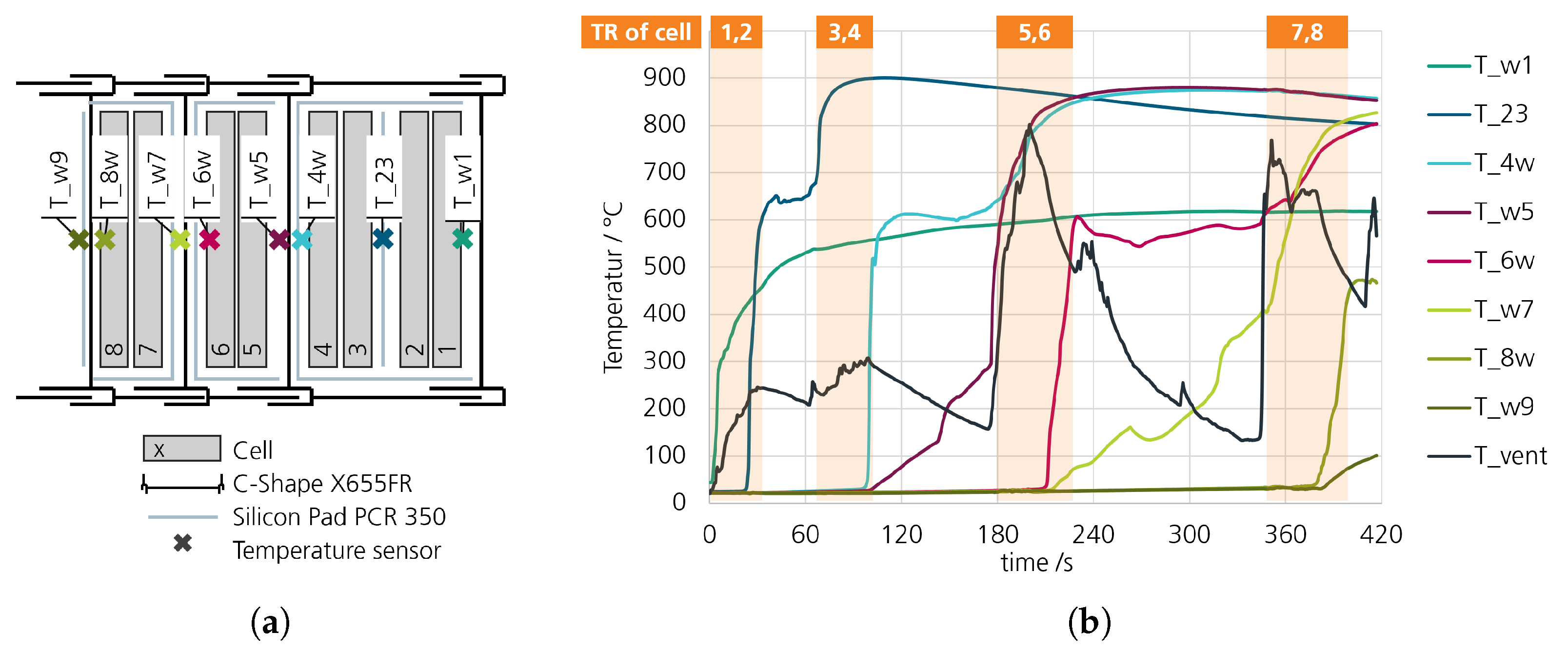
Figure 4a shows the placement of the type K thermocouples. The sensor naming follows T_uv, where u and v indicate the adjacent neighbors (cells or wall “w”).
The module is configured such that four cells are located in the first cell compartment and two cells are located in each of the following compartments. Silicon compression pads (Rogers PCR 350, 1 mm, compressed to 0.5 mm) were used according to
Figure 4a. The module was mounted on an aluminum frame; a steel plate fixed the pneumatic nail actuator to the end plate. To prevent brittle cracking of housing parts, holes were pre-ground through the end plate and the adjacent fire protection plate for the nail passage. The test was conducted in a bunker environment with appropriate gas and smoke extraction. The test commenced by driving a nail 6 mm into the center of the flat side of cell 1 (furthest right in
Figure 4a and in the subsequent test bench images) thereby triggering TR.
3.2. Observations
Upon nail penetration into cell 1, TR initiated immediately, producing a flame jet at the module edge above the nail actuator and a rapid voltage drop of cell 1 to zero within approximately 13 s. Subsequent cells failed sequentially over roughly 360 s. Local temperatures between adjacent cells reached up to 900 °C. In the venting channel, peak temperatures of approximately 800 °C (at 177 s) and 770 °C (at 345 s) were recorded during high-volume venting phases. The complete temperature history is depicted in
Figure 4b, while
Figure 5 shows representative images during cell TR events.
In the four-cell compartment (cells 1–4), the C-shape sidewall failed immediately with the thermal runaway of cell 1 (
Figure 5b), tearing along the labyrinth seal edge and cracking at the junction to the bulkhead wall. Consequently, venting gases escaped through the damaged sidewall, and the burst valves in this compartment did not open. Due to the continuous discharge of burning venting gas, the sidewall exhibits more pronounced signs of heat exposure on the exterior than the two-cell compartments to its left in
Figure 5e. The sidewall at cell 7 and 8 does not show much damage on the outside. In the two-cell compartments (cells 5–6 and 7–8), the burst valves operated as intended (one per chamber), and the gases were guided along the designated path beneath the venting cover (
Figure 5c,e). The 1 mm thick venting cover withstood the thermal runaway of cells 5 and 6. During the thermal runaway of cells 7 and 8, the formation of a small crack was observed. It progressively widened until it spanned close to the full width of the cover.
During the module abuse test, thermal propagation crossed two bulkheads. While the propagation times differed, the temperature responses showed similar patterns in both cases: TR reached the surface of the preceding cell, and its surface temperature increased abruptly to approximately 600 °C. The adjacent (receiving) cell responded about 3 s later with a linear temperature rise of roughly 2.6 K/s. Upon reaching 150 °C, the cells vented, exhibiting distinct outcomes: for cell 5 a temperature jump was observed, whereas for cell 7 a temperature drop occurred.
During the module nail penetration test, the average thermal propagation (TP) time between two adjacent cells was measured to be 14 s. The addition of each compression pad resulted in an increase of 36 s seconds in the TP time. The incorporation of the phenolic bulkhead provided a further increase of 37 s. The Sidewall failure was initiated by internal overpressure and not caused by particle abrasion as expected. This mechanic was detected at the venting cover, following the exposure of the venting gases from three cells.
4. Discussion
Thermal propagation delay: The TP between cell 6 and cell 7 during the module nail abuse test is represented in the C-shaped compartment torch test. In this scenario, cell 7 reached a temperature of 300 °C after 125 s. In contrast, during the 600 °C flame test, this temperature was reached after 254 s. This discrepancy demonstrates that the component-level test is not suitable for quantitatively determining TP times. The test can be further improved by addressing a realistic interface contact pressure, representative thermal masses, and the heat dissipation characteristics of a localized hotspot.
A direct comparison with thermal propagation pause times in other studies is challenging due to numerous influencing factors. Further more, it is evident that a pure phenolic resin wall does not contribute in the same way as specialized barrier materials described in [
9] (>700 s, TP stop), [
10] (>91 s, TP stop), [
11] (TP stop) and [
12] (>2500 s, TP stop). To enhance TP suppression, the strategies presented in these publications could potentially be integrated into the design of injection-molded composite components.
Burst pressure: The valve burst pressure tests provided quantitative measurements of opening pressures. The sidewall failure observed during the module abuse test can be directly attributed to the increased burst pressures measured in the burst valve plate. Therefore, the compressed air test represents a meaningful and reliable method for the development of new burst discs.
Enclosure: Enclosure failure under thermal runaway (TR) loading as suggested by the torch-and-grit test did not occur during the module test: the 2 mm thick sidewalls did not fail due to particle abrasion. Such failure was only observed in the 1 mm thick venting cover. This highlights the difficulty in interpreting the results of the torch-and-grit test, as it is not clear whether the tested exposure can be attributed to specific cell chemistries and local conditions.
The material behavior observed during the high-temperature flame test was representative of the phenolic material under thermal runaway (TR) conditions, as seen in the comparison with the later module abuse test. The extent of damage—indicated by the formation of surface blisters followed by whitening—in both experiments was comparable (except for the burst sidewall).
5. Conclusions
The fabrication of the composite battery module prototypes confirms that complex components can be manufactured using phenolic resins, which provide advantages for protection against TP in housing concepts. As the show module represents an initial research prototype, several areas for improvement were identified. The C-shaped components exhibited the anticipated mechanical performance as long as the internal pressure was correctly released. Further enhancements should focus on enhanced TP suppression.
The burst valves fabricated from phenolic resin performed well, with reliable opening and protective mechanisms, but had excessive opening pressure. While the higher burst pressure resulted in significant secondary issues, these problems can be addressed through straightforward tool optimization and refinement of the manufacturing process.
Preliminary trials on a component level are highly relevant for the development of complex components. However, it was observed that the findings from such trials were not always directly transferable and did not always match the observations in a module abuse test. The conducted tests can be evaluated as follows: The air pressure test of the burst discs provides quantitative results, the observation of heat transfer in the torch test yields qualitative insights and the torch-and-grit test produces results that are difficult to apply in design.
6. Patents
Patents submitted for filing. Application numbers: JP 2022 212337 (PCT JP2023 045612), JP 2022 212343 (PCT JP2023 045614), JP 2022 212354 (PCT JP2023 045615).
Author Contributions
Conceptualization, investigation and Writing: L.J.; Resources: A.D.; Supervision: L.-F.B. and J.T. All authors have read and agreed to the published version of the manuscript.
Funding
We kindly acknowledge Sumitomo Bakelite Europe (Ghent) NV for providing funding support for this research.
Data Availability Statement
The data presented in this study are available on request from the corresponding author. The data are not publicly available due to private cooperation research.
Conflicts of Interest
The authors declare no conflicts of interest. The funders had no role in the design of the study; in the collection, analyses, or interpretation of data; in the writing of the manuscript; or in the decision to publish the results.
References
- Quigley, R. More Electric Aircraft. In Proceedings Eighth Annual Applied Power Electronics Conference and Exposition; IEEE: Piscataway, NJ, USA, 1993; pp. 906–911. [Google Scholar] [CrossRef] [Scilit]
- Tom, L.; Khowja, M.; Vakil, G.; Gerada, C. Commercial Aircraft Electrification—Current State and Future Scope. Energies 2021, 14, 8381. [Google Scholar] [CrossRef] [Scilit]
- Feng, X.; Ouyang, M.; Liu, X.; Lu, L.; Xia, Y.; He, X. Thermal runaway mechanism of lithium ion battery for electric vehicles: A review. Energy Storage Mater. 2018, 10, 246–267. [Google Scholar] [CrossRef] [Scilit]
- Qiu, M.; Liu, J.; Cong, B.; Cui, Y. Research Progress in Thermal Runaway Vent Gas Characteristics of Li-Ion Battery. Batteries 2023, 9, 411. [Google Scholar] [CrossRef] [Scilit]
- Hoelle, S.; Scharner, S.; Asanin, S.; Hinrichsen, O. Analysis on Thermal Runaway Behavior of Prismatic Lithium-Ion Batteries with Autoclave Calorimetry. J. Electrochem. Soc. 2021, 168, 120515. [Google Scholar] [CrossRef] [Scilit]
- Zhang, Y.; Wang, E.; Li, C.; Wang, H. 2D Combustion Modeling of Cell Venting Gas in a Lithium-Ion Battery Pack. Energies 2022, 15, 5530. [Google Scholar] [CrossRef] [Scilit]
- Srinivasan, R.; Thomas, M.E.; Airola, M.B.; Carkhuff, B.G.; Frizzell-Makowski, L.J.; Alkandry, H.; Reuster, J.G.; Oguz, H.N.; Green, P.W.; La Favors, J.; et al. Preventing Cell-to-Cell Propagation of Thermal Runaway in Lithium-Ion Batteries. J. Electrochem. Soc. 2020, 167, 020559. [Google Scholar] [CrossRef] [Scilit]
- John, L.; Liebertseder, J.; De Keyser, H.; Dekeyser, A.; Berg, L.F.; Doppelbauer, M.; Tübke, J. Methodic Development of a Composite Battery Module Housing; Fraunhofer: Munich, Germany, 2024. [Google Scholar] [CrossRef]
- Yu, Y.; Li, Z.; Wang, J.; Mei, W.; Duan, P.; Wang, Q. Advanced ultra-pressure-resistant three-phase composite insulation: Halting thermal runaway in lithium-ion batteries. Energy Storage Mater. 2025, 76, 104148. [Google Scholar] [CrossRef] [Scilit]
- Tang, J.; Wu, X.; Ren, J.; Min, H.; Liu, X.; Kong, Y.; Che, P.; Zhai, W.; Yang, H.; Shen, X. Suppressing thermal runaway propagation of nickel-rich Lithium-ion battery modules using silica aerogel sheets. Process Saf. Environ. Prot. 2023, 179, 199–207. [Google Scholar] [CrossRef] [Scilit]
- Becher, D.; Bauer, M.; Döring, H.; Böse, O.; Friess, B.; Danzer, M.A. Preventing thermal propagation in battery packs using enthalpy supported thermal barriers. J. Energy Storage 2021, 42, 103057. [Google Scholar] [CrossRef] [Scilit]
- Chen, S.; Wei, X.; Wu, H.; Chen, K.; Zhang, G.; Wang, X.; Zhu, J.; Feng, X.; Dai, H.; Ouyang, M. Multi-functional thermal barrier suppresses battery thermal runaway propagation and degradation. Renew. Sustain. Energy Rev. 2025, 223, 116056. [Google Scholar] [CrossRef] [Scilit]
| Disclaimer/Publisher’s Note: The statements, opinions and data contained in all publications are solely those of the individual author(s) and contributor(s) and not of MDPI and/or the editor(s). MDPI and/or the editor(s) disclaim responsibility for any injury to people or property resulting from any ideas, methods, instructions or products referred to in the content. |