1. Introduction
Future aircraft concepts must drastically reduce climate impact, improve efficiency, and remain economically viable [
1,
2]. While current conventional aircraft like the A320 (≈100 kW), A321 (≈150 kW), and A380 (≈600–800 kW) operate with electrical power levels in the range of 100–800 kW, the increasing electrification of systems, first in MEA [
3], then in AEA, drives installed electrical power towards megawatt levels [
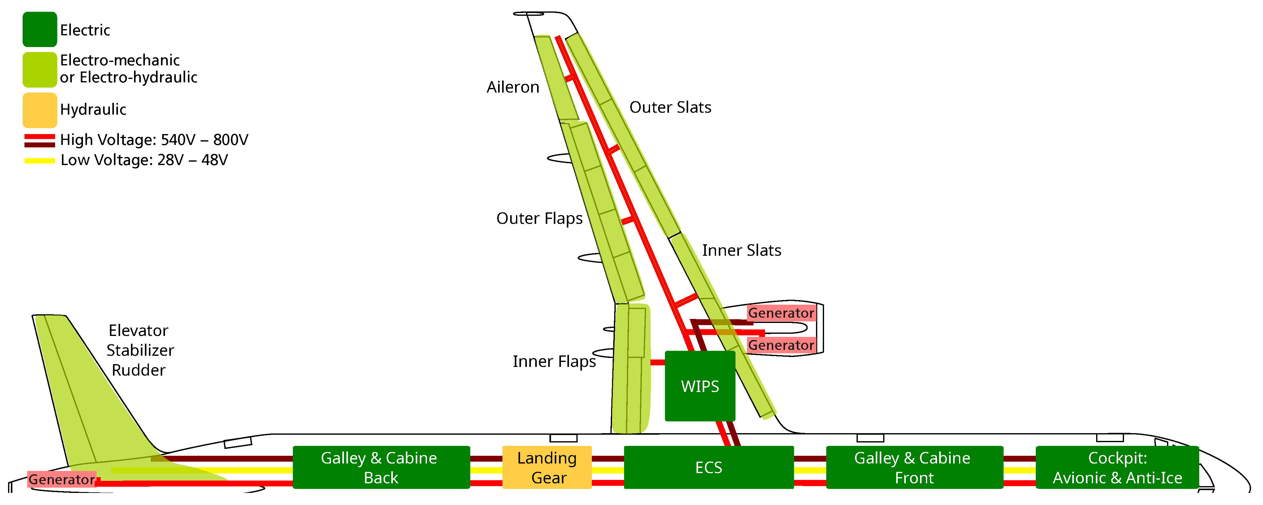
4]. The MEA A350 already reaches ≈800–1000 kW, while the MEA B787 exceeds 1 MW and a hypothetical MEA version of the A321 would require around ≈700 kW (
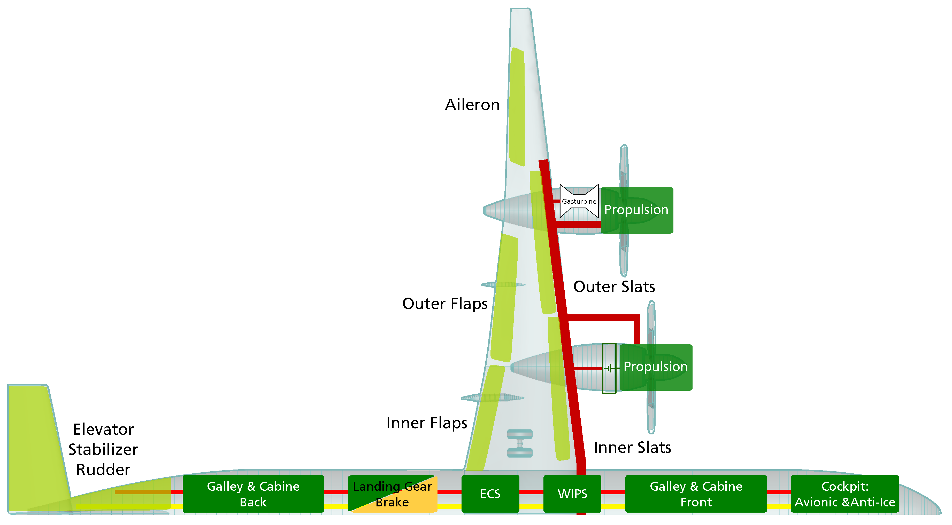
Figure 1). A plug-in battery-electric aircraft (PHEP) conceptualized within a DLR internal study, featuring a partially electric mission powered by batteries and four electric machines, supported by a gas turbine as a range extender, would require ≈17.5 MW for 250 passengers [
5] (
Figure 2).
This shift in power levels fundamentally challenges existing electrical system architectures. Today’s MEA architectures rely on AC grids or hybrid AC/DC grids, combining multiple voltage levels, long wire runs, and numerous protection and isolation devices [
3,
6]. DC grids are now being introduced [
7] as they offer distinct advantages: they eliminate reactive power, allowing higher power transfer for the same wire cross-sections and they enable the efficient integration of batteries and fuel cells [
8,
9]. By way of comparison, the electrical on-board grid of a ship was converted from AC to DC, reducing its volume by 41% and its weight by 56% [
10]. Even if the results cannot be directly transferred to the aircraft, there is a noticeable tendency. DC systems also offer lower losses and simplified control. However, they introduce significant challenges: lower system inertia, more complex fault behavior, the absence of natural current zero crossings complicating safe disconnection and worsening the effect of partial discharges, and increased demands on protection and fault detection as a consequence [
11,
12]. Ensuring reliable fault management is critical, yet disconnection devices remain complex, heavy, and costly.
The growing coupling between the propulsion and the on-board systems means that a single fault can affect large parts of the grid. Protection strategies relying on heavy isolation and complex circuit breakers add weight and volume and limit fault resilience. Safety-critical systems such as primary flight control and avionics rely on an electric power supply, making reliability and availability central design drivers. The transition to AEA requires more than simply replacing conventional systems with electrical counterparts. It demands a fundamental redesign of the electrical system architecture.
The redesign of the electrical system architecture is driven by three key factors: the increase in installed electrical power, the transition to fully electric flight control and the growing demands for reliability and availability. These changes are further amplified by the electrification of the powertrain, which adds another layer of complexity to the system due to the high power requirements. The goal of this research is to reduce system complexity of the EPS while increasing reliability and availability through novel electrical system architectures based on segmentation and on entirely separated or weakly coupled microgrids. By decoupling safety-critical from non-safety-critical systems, fault impact can be limited. In turn, protection strategies can be simplified, EMI problems mitigated, and wire lengths reduced.
2. Methodology
This study applies a structured, three-step methodology to derive EPS architectures for future aircraft. First, the conventional approach is developed by analyzing the state-of-the-art (SoA) in comparable platforms and transferring it to a new aircraft configuration. For existing aircraft, such as adaptations of the A321 to a MEA, this results in a conservative design that prioritizes component availability and certification maturity. In contrast, the disruptive approach explores radically new EPS topologies enabled by emerging technologies. Its potential benefits and limitations are then systematically assessed against the conventional baseline. From this comparative evaluation, an intermediate architecture is synthesized, combining the strengths of both approaches while addressing key trade-offs in complexity, weight, and system integration. All three approaches aim to reduce fault propagation, simplify protection schemes, minimize EMI and wiring mass, and cluster electrical loads by their DAL. While the intermediate approach offers a realistic near-term solution, the disruptive architecture represents a target for entry-into-service 2035.
3. Electric Power System Architectures for More Electric Aircraft
This section presents new MEA EPS architectures featuring a bleedless design with electric WIPS, ECS, and fully electrified flight control systems (
Figure 1).
3.1. Conservative Approach: Segmented Grid
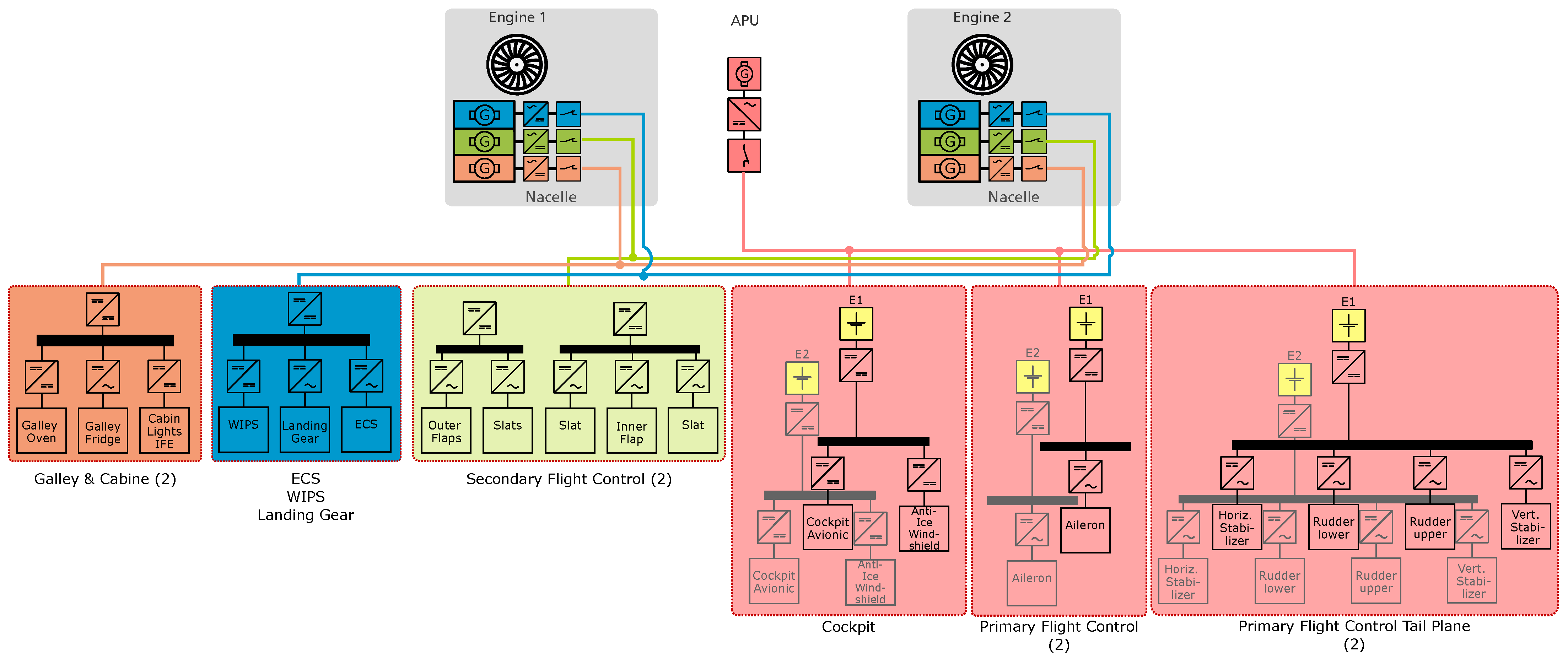
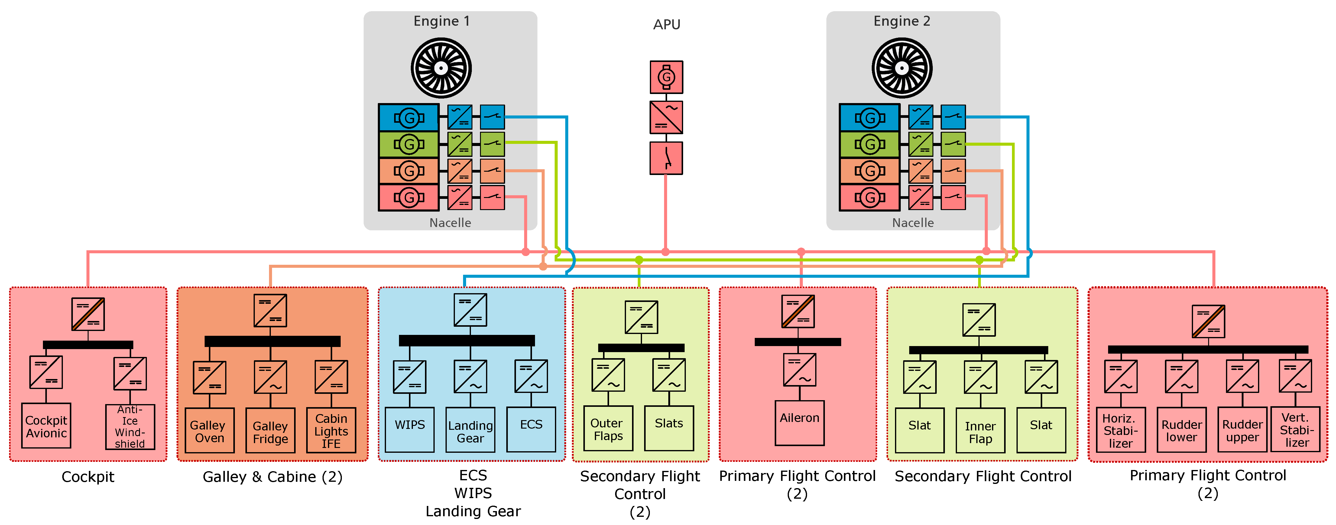
In contrast to the SoA, the EPS is divided into four electrically separate sub-grids, whose supply is assigned to one of the four generators (
Figure 3). Safety-critical loads are in a dedicated safety grid (highlighted in red in
Figure 3). This can be supplied either by one of two primary generators or by the generator of the Auxiliary Power Unit (APU). If these sources fail, the architecture allows for switching to one of the remaining generator strings.
The electrical separation of the sub-grids simplifies fault management: fault detection, localization, and containment can be performed on a sub-grid basis with significantly reduced component count and wire lengths. Fault detection is based on current or noise measurement, both of which are significantly easier in smaller grids. The separation of the grids effectively limits the fault propagation. Since the electrical grids are already segregated, the number of separation or isolation devices is significantly reduced. Voltage levels and grid topologies can be adapted to performance and reliability requirements per sub-grid. The requirements for safety, reliability, EMI, and power quality vary depending on the grid. As a result, certification requirements could differ and be reduced, e.g., for galley and cabin components as there is no longer a connection to safety-critical loads.
The necessary components are available, although the individual generators have lower rated power outputs due to the division. Overall, availability increases compared to the SoA approach, as there are now nine generators available instead of five. Although each individual string cannot supply the entire EPS on its own, the supply of the safety-critical grid remains guaranteed even in the event of multiple failures. Energy and load management strategies are significantly limited. It is not possible to design shared busbars that are then used competitively or to dampen load peaks using sources in other grids.
3.2. Disruptive Approach: Islanded Microgrids
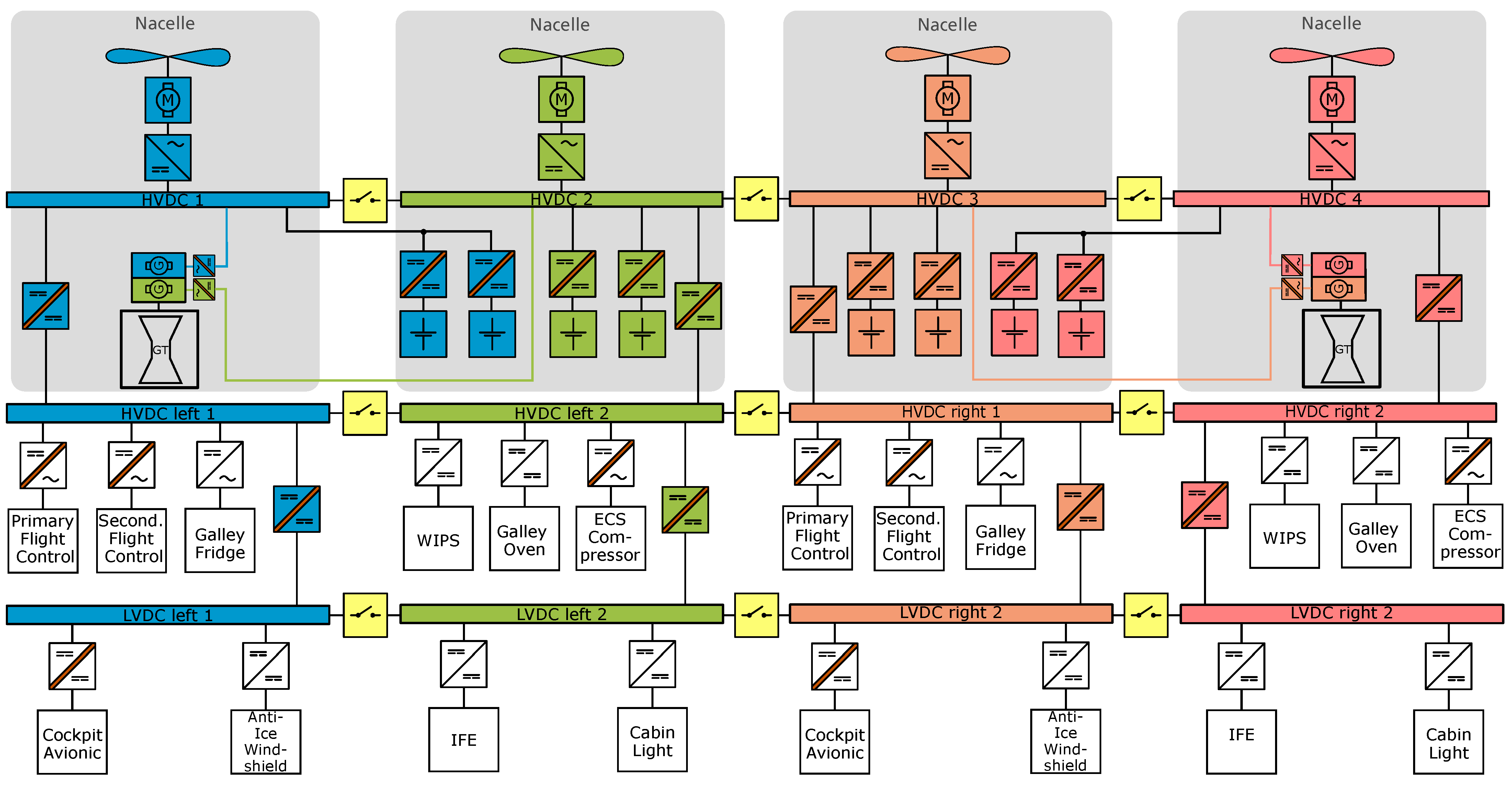
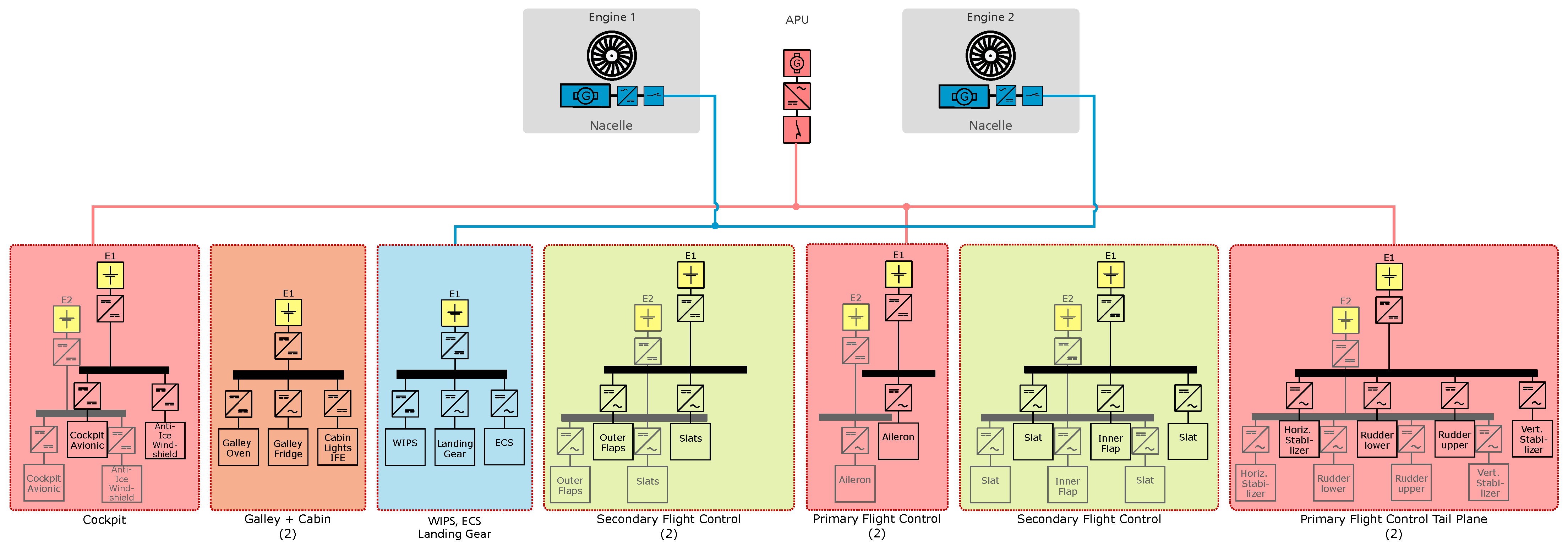
The disruptive approach separates the EPS into electrically disconnected, islanded microgrids (
Figure 4). The propulsion and on-board systems are completely decoupled. This reduces common-cause risks, as without a common busbar, the probability of individual events (e.g., overvoltage, arc fault) simultaneously affecting the propulsion and safety-relevant loads is eliminated. Voltage quality is improved because propulsion-related load changes and harmonics do not couple into, e.g., the avionics and vice versa. Sub-grid-specific optimization is possible to an even greater extent. Filter topologies, dV/dt and dI/dt limitation and grounding concepts can be designed specifically for each sub-grid.
The electrical power supply for the island grids is battery-based (
Figure 4). An exception is the sub-grid with the ECS, which is additionally powered by a generator to avoid the otherwise necessary battery capacity of ≈3 t. The DC bus, power electronics, and batteries are designed redundantly in safety-critical grids. The batteries are reconfigurable (cell isolation in case of failure), which increases availability and reliability. For non-similarity, the safety-critical grid is additionally connected to the APU generator. Compared to the conservative approach, the disruptive one significantly shortens wire lengths, as the battery can be positioned close to the load(s). This reduces line inductance and loop areas, EMI, and the required filter effort. The grid separation reduces the requirements for galvanically isolated power converters. This in turn reduces mass, installation space, and losses, while control dynamics are improved.
The batteries distributed throughout the aircraft and fuselage pose challenges in terms of thermal (runaway) control and maintenance. The batteries are heavier than generators, but in turn, the mass of the electrical wiring system (EWIS) is noticeably reduced and fewer insulation and disconnection devices are required. Another major challenge arises from the charging infrastructure required to charge the on-board batteries, as it imposes substantial demands on the existing airport power and ground infrastructure.
3.3. Intermediate Approach: Separation Between Propulsion and Safety-Critical On-Board Systems
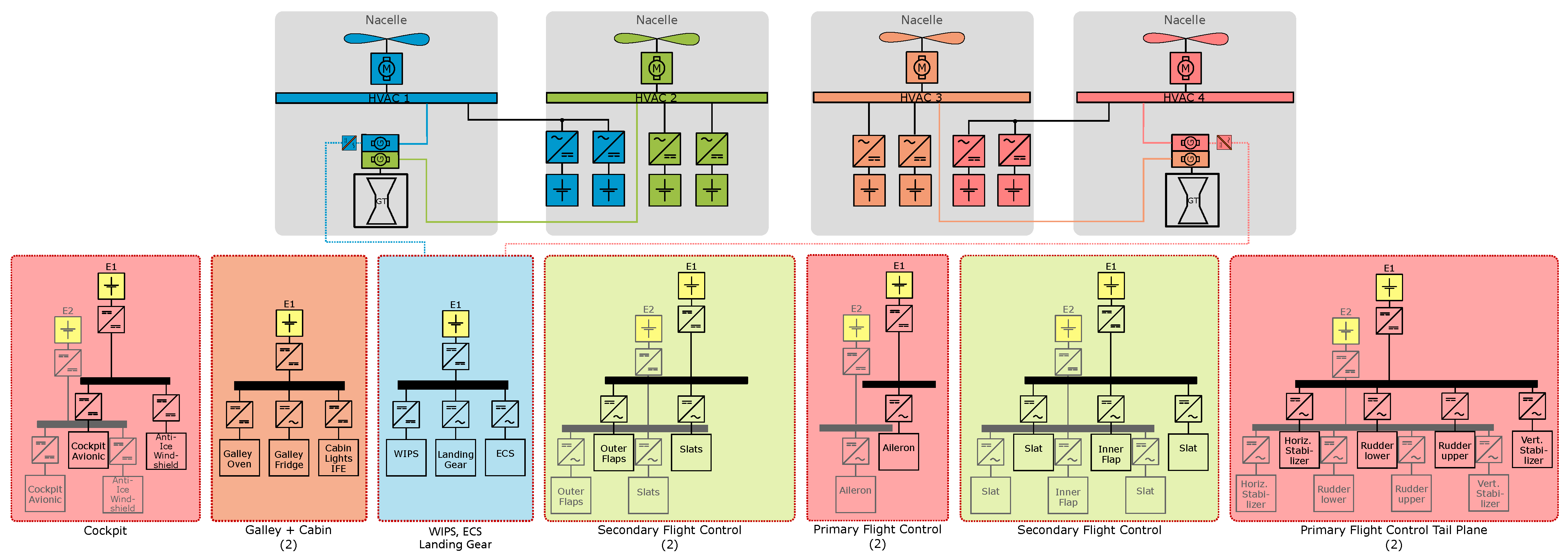
In the intermediate approach, the safety-critical grid is completely decoupled from the propulsion system (
Figure 5). The remaining on-board systems are supplied by engine-driven generators as in the conservative architecture, whereas the safety-critical grid is battery-powered with the APU generator as a backup source. The batteries are charged on the ground via the APU and do not require any charging infrastructure at the airport. One battery is charged after the other.
This architecture constitutes a compromise between the conservative and disruptive approaches: grid segmentation is retained and the safety-critical grid is further isolated from the propulsion and supplied by dedicated batteries. Compared with the disruptive concept, the number of battery packs is substantially reduced. Wire lengths, the count of separation devices, and the need for galvanically isolated power electronic converters increase accordingly. Battery packs are not distributed throughout the fuselage but are confined to the nacelles.
4. Electric Power System Architectures for All Electric Aircraft
The electrical system architecture of the AEA supplies power not only to the on-board systems but also to the propulsion system, with power levels reaching the megawatt range.
4.1. Conservative Approach: Connected Grid
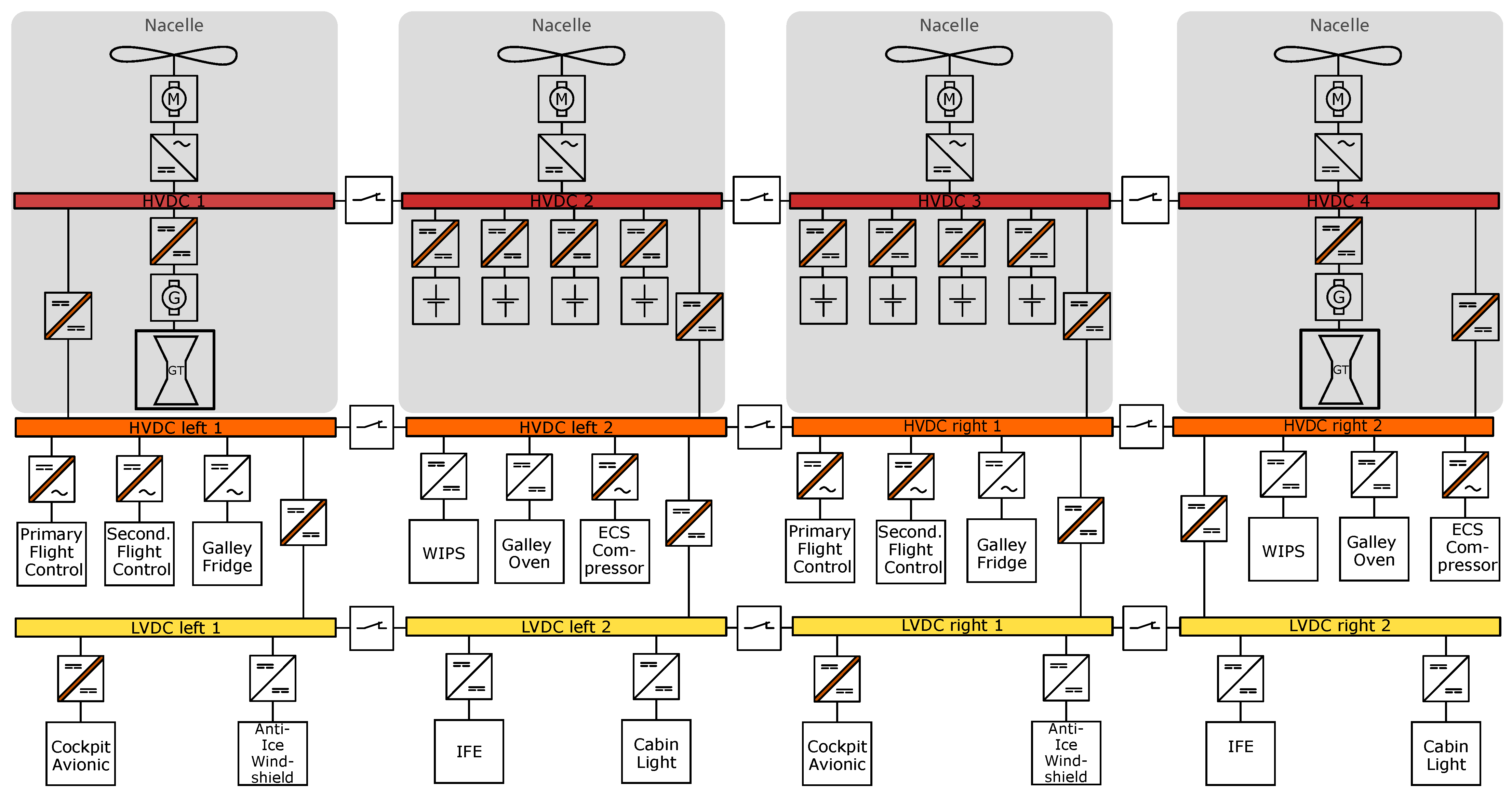
The conservative approach corresponds to a connected grid architecture (
Figure 6) consistent with the SoA. Similar to the EPS configuration of the A321, the system forms a hierarchical, under nominal conditions, connected grid that consists of different voltage levels. According to the propulsion units, the entire EPS is divided into four sub-grids that remain interconnected during normal operation but can be separated in the event of a fault.
This architecture offers several advantages: in the event of engine failure, the available battery capacity can be used to operate or overpower the functional electrical machines, thereby improving system availability. The failure of a single battery pack only has a minor impact on the overall system availability. The placement of the batteries in the nacelles spatially separates the potential fire load from the fuselage, mitigating the consequences of a thermal runaway. This approach enables energy and load management strategies and the shared use of common busbars for improved flexibility.
The connected grid configuration also shows significant disadvantages. Fault currents and line faults can propagate throughout the entire grid, requiring complex protection devices and bulky circuit breakers. Multiple points require galvanic isolation, leading to additional weight and reduced efficiency due to heavy transformers. Disconnection under high-voltage DC conditions poses a considerable arc risk requiring special switches due to the lacking natural zero crossing. Additionally, the large number of parallel connected components increases the magnitude of potential fault currents.
4.2. Disruptive Approach: Islanded Grids
Incorporating batteries enables a shift from centralized (engine-/APU-driven generators) to distributed sources located near the loads. The EPS is partitioned into islanded microgrids that are never electrically interconnected—not even during charging (
Figure 7). Each island is charged via dedicated charging lines, whereby higher voltages can be used on ground to reduce wire cross-section and weight.
The separation improves fault containment and overall safety as batteries are isolated from each other. It lowers fault current amplitudes by avoiding extensive parallel paths and reduces the need for galvanically isolated conversion stages. Single-line faults have less severity and impact. Shorter wire lengths reduce EMI and filter size. The separation of safety-critical and non-critical grids simplifies certification. Although batteries increase the component mass, this is offset by weight reductions in cabling and protective devices.
The approach has trade-offs: Batteries are distributed throughout the aircraft and fuselage, which complicates integration, inspection, and thermal management. In the event of engine failure, capacity in other grids cannot directly support propulsion unless power is explicitly routed through protected charging lines. By design, cross-island power transfer is otherwise prevented. For additional (dis)advantages, refer to
Section 3.2.
4.3. Intermediate Approach: Zonal Grid
In the zonal grid approach, the EPS is divided into four sub-grids that are electrically disconnected under normal operating conditions (
Figure 8). Following a fault analysis, interconnection between zones is enabled in degraded modes to maintain functionality.
Availability is preserved in engine-out scenarios by allowing remaining battery capacity to power the operative electric machines. Isolation of individual battery packs limits the impact of failures, while nacelle placement spatially segregates potential fire loads from the fuselage. Confining faults within zones reduces the severity and propagation of single-line failures compared with a connected grid. Fewer parallel paths lower fault-discharge currents. High-voltage DC disconnection risks (arcing) are markedly reduced. Safety-critical loads also benefit from diversified sources, since gas turbine generators and batteries can be reconfigured to ensure continued supply within the affected zone. The electrical isolation of the battery systems improves fail safety. The risk associated with high-voltage DC connection is significantly lower compared to disconnection.
Several challenges remain: galvanic isolation is required at multiple interfaces, adding weight and reducing system efficiency due to heavy isolation transformers. Moreover, the zonal concept does not inherently separate safety-critical from non-critical grids, which limits reliability, fail safety, and certification simplifications.
5. Weight
A critical factor in assessing the feasibility of implementing islanded grids is the battery mass. The battery mass was estimated for a total flight duration of
h. The grid containing the ECS is powered battery-electrically for
h, followed by conventional operation via gas turbines for the remainder of the flight. The DC/DC converter efficiency was set to 98.6% and the battery discharge efficiency to 96%, reflecting SoA system performance [
5]. Wire losses were neglected in this preliminary analysis and the electrical loads, along with their respective utilization factors, were characterized based on representative operational data. This approach enables a realistic first assessment of the technical feasibility (
Table 1). The weight of the batteries is partially offset by lower fuel mass or main battery mass.
6. Conclusions
This study proposes and evaluates novel electrical system architectures for future MEA and AEA. All approaches are based on the principle of segmenting the EPS into several sub-grids. The analysis covers three architecture classes, conservative, disruptive, and intermediate, with each one offering different trade-offs between complexity, reliability, and feasibility. The disruptive approach introduces fully isolated microgrids in which electrical loads are grouped according to their DAL and spatial location. Each microgrid is powered locally, significantly reducing wire lengths, EMI, the number of components, and the mass of the EWIS. This configuration also improves fault detection and management, limits fault propagation, and reduces insulation requirements. The separation between safety-critical and non-critical loads enables simplified certification strategies. Battery weight estimates for a representative mission profile of h show that the integration of distributed energy storage is technically feasible from the weight perspective. Although batteries increase the component mass, this is offset by weight reductions in cabling and protective devices.
The presented architectures offer viable ways to meet the increasing demands on installed electrical power and the advanced reliability requirements, particularly in the context of electric flight control and partially electrified propulsion systems. By introducing decentralized, decoupled microgrid structures, significant improvements in system efficiency, reliability and scalability can be achieved.
Author Contributions
A.R.: conceptualization, methodology, architecture design, writing—original draft, writing—review and editing, visualization. F.L.J.v.d.L.: conceptualization, supervision, writing—review and editing, visualization, funding acquisition. All authors have read and agreed to the published version of the manuscript.
Funding
The project is supported by the Clean Aviation Joint Undertaking and its members, and funded by the European Union under Grant Agreement No 101102011. The views and opinions expressed are however those of the authors only and do not necessarily reflect those of the European Union or the Clean Aviation Joint Undertaking. Neither the European Union nor the granting authority can be held responsible for them.

Data Availability Statement
There is no data publicly available.
Acknowledgments
The authors thank Mohamed Osama for numerous discussions and advice.
Conflicts of Interest
The authors declare no conflicts of interest.
Abbreviations
The following abbreviations are used in this manuscript:
| AC/DC | Alternating Current/Direct Current |
| AEA | All Electric Aircraft |
| APU | Auxiliary Power Unit |
| DAL | Design Assurance Level |
| DC/DC | Direct Current to Direct Current |
| ECS | Environmental Control System |
| EMC | Electromagnetic Compatibility |
| EMI | Electromagnetic Interference |
| EPS | Electrical Power System |
| EWIS | Electrical Wiring Interconnection System |
| GT | Gas Turbine |
| MEA | More Electric Aircraft |
| PHEP | Plug-in Hybrid Battery-Electric Powered |
| SoA | State of the Art |
| WIPS | Wing Ice Protection System |
References
- Staack, I.; Sobron, A.; Krus, P. The potential of full-electric aircraft for civil transportation: From the Breguet range equation to operational aspects. CEAS Aeronaut. J. 2021, 12, 803–819. [Google Scholar] [CrossRef] [Scilit]
- Aguida, M.E.; Che, Y.; Yang, J. Technological advancements and future prospects of electrical power systems for sustainable more electric aircraft. Propuls. Power Res. 2024, 13, 475–486. [Google Scholar] [CrossRef] [Scilit]
- Sarlioglu, B.; Morris, C.T. More electric aircraft: Review, challenges, and opportunities for commercial transport aircraft. IEEE Trans. Transp. Electrif. 2015, 1, 54–64. [Google Scholar] [CrossRef] [Scilit]
- Woodworth, A. Megawatt and Beyond, NASA’s Electrified Aircraft Propulsion. In Proceedings of the Workshop on Power Electronics for Aerospace Applications, Glasgow, UK, 23–24 July 2025. [Google Scholar]
- Atanasov, G.; Silberhorn, D. Bridging Scale and Sustainability: A Battery-Electric Aircraft with Range Extenders for Flexible Short- to Medium-Range Operations. In Proceedings of the 15th EASN International Conference on Innovation in Aviation & Space Towards Sustainability Today and Tomorrow, Madrid, Spain, 14–17 October 2025. [Google Scholar]
- Radomsky, L.; Keilmann, R.; Ferch, D.; Mallwitz, R. Challenges and opportunities in power electronics design for all-and hybrid-electric aircraft: A qualitative review and outlook. CEAS Aeronaut. J. 2024, 15, 751–764. [Google Scholar] [CrossRef] [Scilit]
- Xu, L.; Guerrero, J.M.; Lashab, A.; Wei, B.; Bazmohammadi, N.; Vasquez, J.C.; Abusorrah, A. A review of DC shipboard microgrids—Part I: Power architectures, energy storage, and power converters. IEEE Trans. Power Electron. 2021, 37, 5155–5172. [Google Scholar] [CrossRef] [Scilit]
- Buticchi, G.; Bozhko, S.; Liserre, M.; Wheeler, P.; Al-Haddad, K. On-board microgrids for the more electric aircraft—Technology review. IEEE Trans. Ind. Electron. 2018, 66, 5588–5599. [Google Scholar] [CrossRef] [Scilit]
- Zhao, X.; Guerrero, J.M.; Wu, X. Review of aircraft electric power systems and architectures. In Proceedings of the 2014 IEEE International Energy Conference (ENERGYCON); IEEE: New York, NY, USA, 2014; pp. 949–953. [Google Scholar]
- Chang, G.; Wu, Y.; Shao, S.; Huang, Z.; Long, T. DC bus systems for electrical ships: Recent advances and analysis of a real case. IEEE Electrif. Mag. 2020, 8, 28–39. [Google Scholar] [CrossRef] [Scilit]
- Molligoda, D.A.; Chatterjee, P.; Gajanayake, C.J.; Gupta, A.K.; Tseng, K.J. Review of design and challenges of DC SSPC in more electric aircraft. In Proceedings of the 2016 IEEE 2nd Annual Southern Power Electronics Conference (SPEC); IEEE: New York, NY, USA, 2016; pp. 1–5. [Google Scholar]
- Jiang, J.; Li, Z.; Li, W.; Ranjan, P.; Wei, X.; Zhang, X.; Zhang, C. A review on insulation challenges towards electrification of aircraft. High Volt. 2023, 8, 209–230. [Google Scholar] [CrossRef] [Scilit]
| Disclaimer/Publisher’s Note: The statements, opinions and data contained in all publications are solely those of the individual author(s) and contributor(s) and not of MDPI and/or the editor(s). MDPI and/or the editor(s) disclaim responsibility for any injury to people or property resulting from any ideas, methods, instructions or products referred to in the content. |