Proceeding Paper

Experimental and Numerical Investigation of Cooling Ducts for Thermal Management of Fuel Cell-Based Aero Engines †
Institute of Electrified Aero Engines, German Aerospace Centre (DLR), 03046 Cottbus, Germany
*
Author to whom correspondence should be addressed.
Presented at the 15th EASN International Conference, Madrid, Spain, 14–17 October 2025.
Eng. Proc. 2026, 133(1), 105; https://doi.org/10.3390/engproc2026133105
Published: 10 May 2026

Abstract

Effective thermal management is crucial for the development of future electrified aircraft propulsion systems. One of the most challenging phases is the take-off phase, which imposes particularly high demands on cooling systems. In addition, the aerodynamic drag during cruise flight has to be kept to a minimum. This study introduces a novel experimental thermal management system using a test stand with a modular air duct (TMTmad), which is designed specifically to investigate different configurations of air supply and heat exchanger in fuel cell-based electrified propulsion systems. Given the versatility of nacelle-integrated electrified propulsion architectures, this approach offers high flexibility in the design and integration of thermal management systems. This includes aspects such as the location, orientation and geometry of an air-cooled heat exchanger (HEX), as well as the inlet and outlet configurations. Moreover, the optimization of the uniform flow guidance of the duct flow within the nacelle and the integration of additional fans to ensure airflow under critical conditions can be studied. The main heat source delivers up to 6 k W of heating power with a temperature range from −20 °C to 200 °C. The study measures the heat flux and pressure losses within these systems and includes a thorough fluid flow analysis. Furthermore, the experimental data serves as a valuable resource for validating numerical models of cooling ducts, enhancing the accuracy and reliability of future design iterations.

1. Introduction

A Thermal Management Test stand with a modular air duct (TMTmad) was built to study the heat and fluid flow of the air sides of thermal management systems in electrified aero engines. The final topologies of these propulsion systems have not yet been fully clarified, which leads to variations in their integrated designs [1,2]. All-electric systems consist of an electric motor that drives a propeller, often with a gear box in between. An inverter and converter deliver the electrical current using a low voltage DC current from batteries or fuel cell systems. The fuel cells need an air supply system as well as a hydrogen supply, wherein the air and hydrogen need to be thermodynamically conditioned. The propulsion system generates waste heat, and thus, heat sinks across the system are used to increase the overall efficiency of the drive train. Integrated designs for aero engines range from fully integrated nacelle designs to the partial integration of some subsystems. It must also be considered that the propeller can be in a push or a pull configuration. The main heat source in a hydrogen-based electrical aero engine is the fuel cell itself. Fuel cell types considered for aeronautical applications are Low Temperature Proton Exchange Membrane (LTPEM) fuel cells, High Temperature Proton Exchange Membrane (HTPEM) fuel cells and Solid Oxid Fuel Cells (SOFCs) [3]. Recently, Intermediate Temperature PEM fuel cells have also been developed, raising the temperature level of LTPEM cells.
The challenge with SOFCs is to precondition of the entire system to high temperatures and pressures as well as to optimize the weight of the system, including its balance of plant [4], while the technology’s readiness still needs to be developed. LTPEM fuel cells are accessible and have been strongly developed for power ranges suitable for aviation. The challenge when using LTPEM fuel cells is their low temperature level, in the range of T LTPEM = 80   ° C to 90   ° C [5,6]. This leads to a small temperature difference from the atmospheric conditions, where in hot and high-altitude conditions, the temperatures at an airfield can reach up to T Atm = 50   ° C during take-off. To reject heat transfer Q ˙ of, i.e., 1 M W in dry air (with heat capacity c p = 1.01 k J / k g / K 1 ) with a temperature difference Δ T of 20 K , a mass flow of m ˙ = Q ˙ / c p Δ T = 49.5 k g / s 1 is needed, which results in an air volume flux V ˙ of approximately V ˙ = 41.2 m 3 / s 1 . Especially at take-off, and partially during the climb, the ram air will not be sufficient to generate this mass flow, and, therefore, additional fans will be necessary for this case. Additionally, other subsystems add further requirements for thermal stability, cooling processes, and pre-conditioning [6].
As the integrated design offers limited space for cooling ducts, a large amount of heat has to be expelled into the air, with strong restrictions in terms of spatial positioning. Additionally, the weight of the cooling system, driven by the Heat Exchanger (HEX), will add a significant increase in the airplane’s overall mass [5]. Furthermore, the HEX adds a significant amount of drag to the airplane, influencing its overall aerodynamics [7]. This leads to a major decrease in the overall efficiency of fuel cell-driven propulsion systems. Additionally, the cooling system adds a substantial amount of aerodynamic drag to the airplane, which, again, reduces its overall efficiency. Thus, the design of cooling ducts for electrified aero engines is a crucial aspect of incorporating efficient propulsion systems into future aviation. The present study focuses on an experimental investigation of cooling duct flows, incorporating the boundary conditions of electrified aero engines. The experiment is designed to offer various geometrical conditions to study such cooling systems in order to enable validation of numerical simulations on such cooling ducts [8]. Further, the investigation of cooling concepts in the experimental facility offers a strong basis of variations, such as testing of new HEX designs, particle separators, security grids, particle filters, fans, flow guidance for uniform fluid flow and especially the interactions across the cooling duct.

2. Experimental Setup

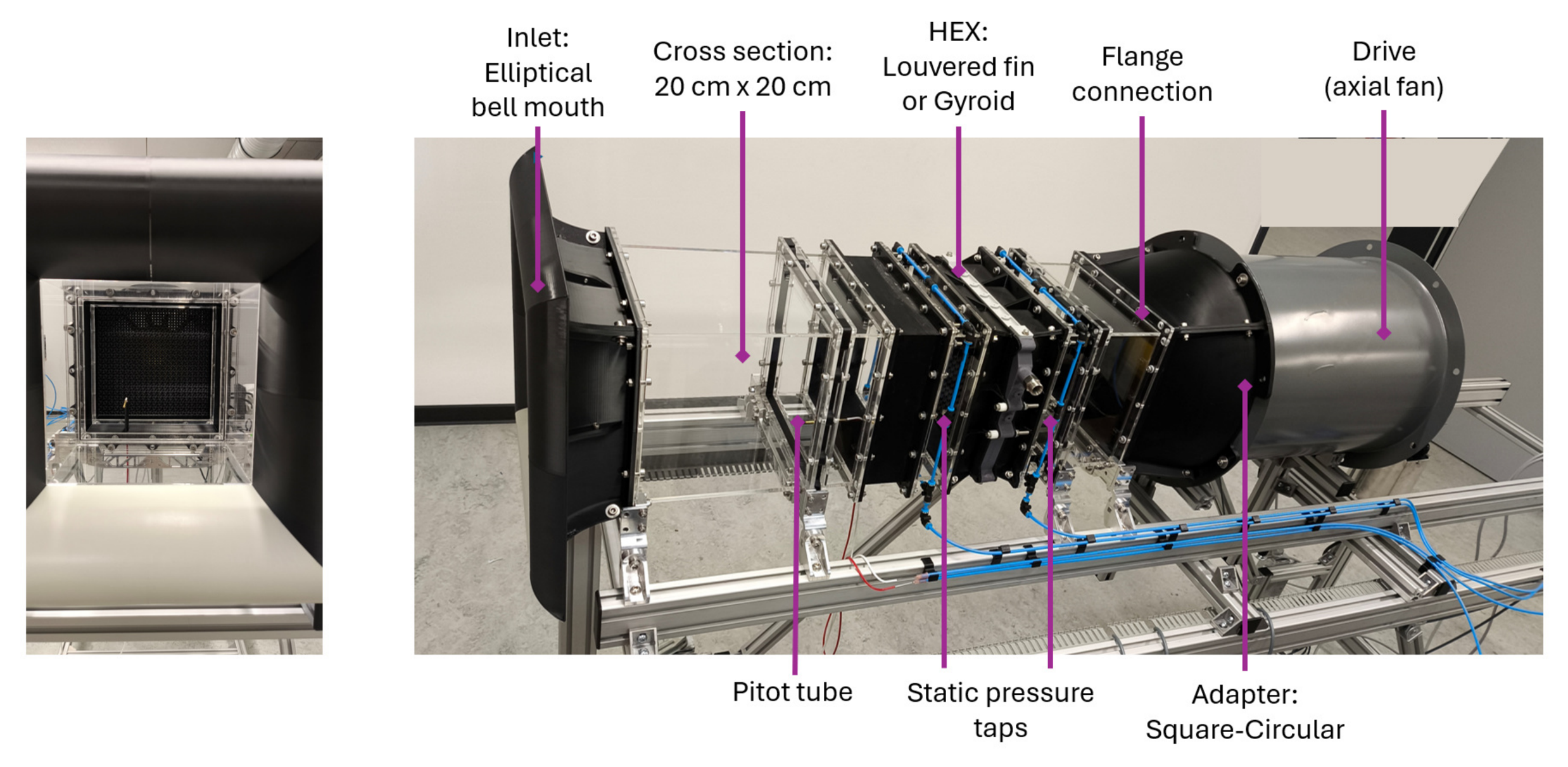
The experimental setup consists of a series of segments. These segments are constructed with flange connections that allow the interconnection of all segments in any order. Thus, the sequence of the segments can be varied and segments can be exchanged or added. This leads to a flexible range for the duct flow and enables the investigation of the individual influences of different segments. In Figure 1, the system is depicted in two exemplary assemblies. The first version (left) is the basic straight duct, using an inlet, standard fin-plate HEX, adapter segment and fan segment. The second version (right) incorporates S-shaped bends of 30   ° C to study flow guidance and non-uniform flow conditions across the duct. Generally, uniformity in the fluid flow velocity is important to ensure the effectiveness of the HEX. However, the limited space does not allow for the use of a traditional flow straightener and settling chamber parts. Thus, considering passive flow control in short ducts is a field of ongoing research. Figure 2 shows the setup of the straight-line duct arrangement.
The basic cross section of the system is a square of A in = D × D = 0.2   m × 0.2   m that is connected to the various segments. These segments are made of acrylic glass to enable access for optical measurement techniques like background-oriented schlieren, particle image velocimetry or particle tracking. A series of segments with lengths 40   c m , 20   c m , 10   c m and 5   c m enable variable length configurations in steps of 5   c m . Two of the short segments are equipped with pressure tap drillings with an inner diameter of d p t = 0.4   m m , which are placed on all four circumferential sides in a mid-lateral position. The four taps are connected together using a flexible pipe ring to produce an averaged static pressure measurement at this location. These segments can be positioned in the system to measure the static pressure losses along the flow. The inlet is an additively manufactured elliptical bell mouth with ellipsis radii of r e l l , 1 = 0.1   m ,   r e l l , 2 = 0.05   m to ensure a smooth inflow without flow separation at the inlets. Varying HEXs can be assembled using 3D-printed adapters placed in between each HEX. In the present study, an AKG (T1) louvered fin HEX (AKG, Dortmund, Germany) [9] is used for the measurements. This ensures valid measurements of the heat exchange and flow behavior across the HEX inside the TMTmad. The air side plate separation height of this HEX is h fin = 11 m m while the thickness of the plate in which the coolant circulates is 4.5 m m .
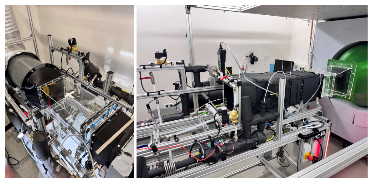
The test set-up was operated in two scenarios, as shown in Figure 3: (1) An installed axial blower was used to drive the flow (left) and (2) the TMTmad was attached to the aeroacoustic wind tunnel of the Brandenburg University of Technology Cottbus-Senftenberg (right). For the first approach, a Ruck AL 315 EC 01 axial fan (ruck Ventilatoren GmbH, Boxberg, Germany) was used, which can provide the system with volume flow rates of up to 1.2   m 3 / s 1 , resulting in an air speed of u = 30   m / s 1 for the cross section of the segments without the HEX. Thus, the duct Reynolds number Re = u   ·   D   ·   ν 1 reaches up to 5 × 10 5 , while the HEX’s inner Reynolds number, based on the plate separation height Re fin = u   ·   h fin   ·   ν 1 = Re   ·   h fin   ·   D 1 , is given by the constant factor of 5.5 × 10 2 and reaches up to 27 , 500 . To connect the circular axial fan and the square duct, an adapter segment is designed and 3D printed. In addition to the given configurations, this system offers the ability to add further segments to study the effect of HEXs, grids or filters. The entire cooling duct is built on a frame of aluminum profiles to enhance the flexibility and mobility of the experiment. The HEX is provided with heat of up to 6.2 k W by a dynamic temperature control system (Huber CC 510, Huber, Offenburg, Germany) and two additional 2 k W immersion heaters. The working fluid is water, which is heated to a set temperature of up to 80 °C and pumped through the system at given flow rates. Additionally, the flow rates in the system are measured by the SM6120 volume flux sensor from ifm electronics (Mulgrave, Australia) up to ≈5 L / min . The outlet temperature depends on the experiment’s heat flux and is measured by PT100 sensor. Additionally, a PT100 is used before the HEX to measure the temperature decrease Δ T l i q on the liquid side. It should be noted that the system operates at Mach numbers Ma = u c sound ,   air 1 between 0.0035 and 0.0873 , which can be considered incompressible flow, and does not reflect the cruising Mach number of a regional aircraft. For comparability of the aerodynamics of the HEX in this experiment to one in an aircraft it is not necessary for the cruising Mach number to be matched, as in a realistic cooling duct, the subsonic RAM air has to be slowed down to an incompressible regime, by, e.g., a divergent duct design. This deceleration would be needed to keep the drag on the HEX small and to avoid shockwaves at the HEX Matrix, which would produce a significant amount of additional drag in the system.
The air temperature of the incident flow is measured by another PT100 sensor, and an installed Pitot tube measures the actual dynamic pressure in the inflow region. Preliminary measurements have been conducted with a traversable Pitot tube to ensure the spatial uniformity of the air flow in the cross section, which was achieved with a tolerance < 1 % . Another PT100 sensor is used behind the HEX to measure the air outlet temperature. In Table 1, the investigated cases within this study are summarized. One of these parameter sets takes approximately 1 h to measure. The environmental pressure and temperature of the experiments are not controlled, but their thermodynamic properties are tracked throughout. The temperature of the room slightly increased during the experimentation. However, a temperature increase of 8 K per hour was not exceeded.

3. Results

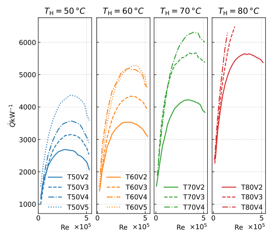
The resulting heat removal for the measured parameter sets, as shown in Table 1, is illustrated in Figure 4. It was observed that the amount of heat removed by the HEX varies strongly with the bath temperature T in , liq , the volume flow of the liquid coolant and the air speed Reynolds number. It was found that the removed heat increases with an increase in volume flow in the liquid cooling system. For instance, for a bath temperature of 50 °C a change in the volume flow from 2   L / min 1 to 5   L / min 1 caused an increase of ≈45% of the rejected heat (see Figure 4, case T50V2 and T50V5). The same behavior was observed for all bath temperatures investigated, where for the highest temperatures, the maximal available heat during experiments was reached for high air flow Reynolds numbers.
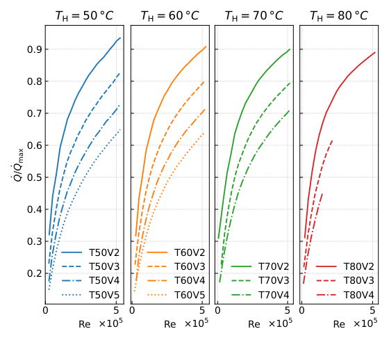
An increase in the heat bath temperature enhances the heat removal due to a larger temperature gradient between the HEX and the incoming air. Furthermore, an increase in Reynolds number also enhances the amount of removed heat up to a maximum of around Re 350 , 000 . For higher Reynolds numbers, a significant reduction in heat transfer of up to 20   % was measured. The reason for this is that higher Reynolds numbers were measured chronologically after the lower ones, and the temperature of the incident air flow T in , air increased slightly between the measured points. Consequently, T in , air was measured accordingly. Thus, the maximal available temperature difference T in , liq T in , air also changed, which influenced the maximal rejectable heat flux
Q ˙ max = c p , liq ( T in , liq T in , air ) m ˙ liq ,
where m ˙ liq = ρ liq V ˙ liq is the mass flow rate of the coolant and ρ liq is its density. The effectiveness of heat exchange is quantified as the ratio of rejected heat flux and the maximal rejectable heat
Q ˙ Q ˙ max = T in , liq T out , liq T in , liq T in , air ,
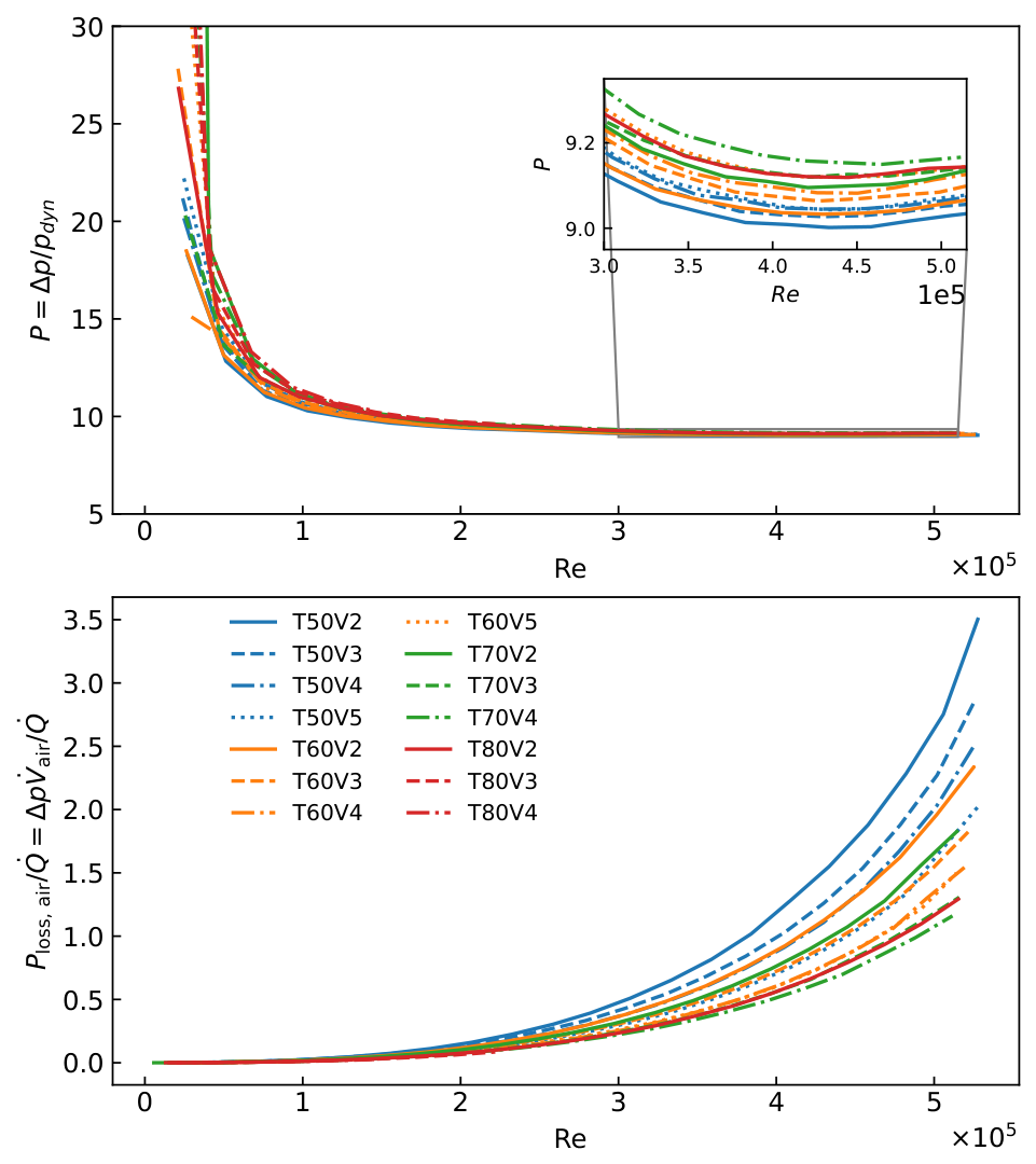
which is depicted in Figure 5. Here, it is notable that the effectiveness of the given HEX behaves differently from the rejected heat. Whereas the rejected heat (see Figure 4) decreases with high Reynolds numbers, the effectiveness of the HEX increases, as the air temperature during the high Reynolds number experiments was increased significantly. This is also due to the increased pressure loss induced by heating. For a given bath temperature, the effectiveness of the heat rejection decreases with the flow rate, whereas the heat flux increases (see Figure 4). For fixed volume rates, the effectiveness decreases with increasing bath temperatures; thus, this influence can be seen as a minor dependency. To reject heat, the system faces friction against the flow that results in a parasitic power loss during heat rejection. The required coolant pumping power is given by the internal liquid pressure loss and the volume rate P loss , liq = Δ p HEX , liq V ˙ liq as well as the air pumping power of the HEX P l o s s , a i r = Δ p V ˙ air = Δ p u A in . Typically, the coolant side losses are negligible in comparison to the air side losses. For the highest volume rate of 5   L / min 1 , a pressure loss of Δ p HEX , liq = 4600 Pa is measured, resulting in a required coolant power loss of P loss , liq = 0.36 W . The air side pressure coefficient of the AKG T1 Louver Fin HEX is shown in Figure 6 (top graph). All cases observed converge in a range of P = 9 and 9.3 for high air Reynolds numbers. For higher bath temperatures, which lead directly to higher outlet air temperatures, a higher pressure loss is measured. The resulting air pumping power required for the rejected heat is depicted in Figure 6 (bottom graph). It can be seen that, for high Reynolds numbers, the resulting air pumping power reaches two times the quantity of the rejected heat. This pumping power results in a heating of the air as well as the heat exchanger’s surface temperature due to thermo-viscous effects. Due to this increase and the rejected heat, the environmental temperature T in , air also increases, reducing the available temperature difference, as shown in Figure 4, for high Reynolds numbers. This results in a decrease in the heat flux for high Reynolds numbers, as shown in Figure 4. The reader should note that the illustration of Q / Q max in Figure 5 compensates for this change in T in , air .
A change in HEX effectiveness can be more quickly achieved through a change in liquid volume flow than through a change in air velocity. The highest heat removal from the system was measured around 6 k W , which is the maximum power of the Huber CC 510 heat bath with two additional 2 k W heaters. Measurements at higher Reynolds numbers for a bath temperature of 80   ° C are not included in this study, because they exceed the power limit of the heat source (see Figure 4, Case T80V2-T80V4). It can be concluded that the setup is potentially capable of performing a heat transfer that exceeds 6 k W .

4. Conclusions

This study introduced a novel experimental thermal management test stand with a modular air duct (TMTmad), which was designed to investigate different configurations of the air supply and heat exchanger in fuel cell-based electrified propulsion systems. The TMTmad offers high flexibility for study design and the integration of cooling ducts in thermal management systems. With this system, customization of the location, orientation and geometry of air cooled heat exchangers, inlet and outlet configurations, flow guidance for uniform flow and the integration of fans are enabled. The present study shows the availability of the experimental setup and summarizes the potential of experiments using this state-of-the-art HEX and fan assembly. For given air and coolant temperatures, the air flow speed and coolant volume rates are varied, while the heat rejection and its induced pressure losses are quantified.
The correlation of converged pressure coefficients and bath temperature can be explained through the thermo-viscous effects of air because the viscosity of air increases with temperature. A slightly lower pressure drop at a bath temperature of 70 °C than at 50 °C can be observed. Furthermore, the experimental data serves as a valuable resource to validate numerical simulations of cooling ducts, such as that in [8], enhancing the accuracy and reliability of future design iterations. In upcoming studies, the experiments will consider a more complex system, such as one involving diffusors, more complex duct geometry, and angled Heat exchangers. Furthermore, we plan to control the environmental temperature.

Author Contributions

Conceptualization, S.M. and F.-T.S.; methodology, S.M., F.-T.S., P.S. and J.H.; software, J.H.; validation, F.-T.S., P.S., C.S. and J.H.; formal analysis, S.M., F.-T.S., P.S. and C.S.; investigation, S.M. and F.-T.S.; resources, S.K. and S.d.G.; writing—original draft preparation, S.M. and F.-T.S.; writing—review and editing, all; visualization, F.-T.S. and J.H.; supervision, S.M., S.K. and S.d.G.; project administration, S.M. and C.S.; funding acquisition, S.M., S.K. and S.d.G. All authors have read and agreed to the published version of the manuscript.

Funding

This research received no external funding.

Institutional Review Board Statement

Not applicable.

Informed Consent Statement

Not applicable.

Data Availability Statement

The raw data supporting the conclusions of this article will be made available by the authors on request.

Acknowledgments

We would like to acknowledge the Brandenburg University of Technology Cottbus-Senftenberg for the use of the aero-acoustic wind tunnel. Further we would like to thank Marc-Kevin Schley for the support during set-up and measurements.

Conflicts of Interest

The authors declare no conflict of interest.

Abbreviations

The following abbreviations are used in this manuscript:
TMSThermal Management System
HEXHeat exchanger
LTPEMLow temperature proton exchange membrane
HTPEMHigh temperature proton exchange membrane
SOFCSolid oxide fuel cell
TMTmadThermal management test stand: modular air duct

References

  1. Adu-Gyamfi, B.A.; Good, C. Electric aviation: A review of concepts and enabling technologies. Transp. Eng. 2022, 9, 100134. [Google Scholar] [CrossRef] [Scilit]
  2. de Graaf, S.; Bahrs, V.; Tarbah, N.; Kazula, S. H2Electra—A platform for comparative analysis of integration concepts for hydrogen-based Electric propulsion in regional aircraft. J. Phys. Conf. Ser. 2024, 2716, 012007. [Google Scholar] [CrossRef] [Scilit]
  3. Kazula, S.; de Graaf, S.; Enghardt, L. Review of fuel cell technologies and evaluation of their potential and challenges for electrified propulsion systems in commercial aviation. J. Glob. Power Propuls. Soc. 2023, 7, 43–57. [Google Scholar] [CrossRef] [Scilit]
  4. Mantelli, L.; Dubey, A.; Buzzola, D.; Ferrari, M.L.; Pontika, E.; Kazula, S.; Ewald, D.; Weber, A.; de Graaf, S. Methodology for Exploring SOFC System Layouts in a Highly Integrated Hybrid Propulsion System. In Proceedings of the 70th ASME Turbomachinery Technical Conference and Exposition, Memphis, TN, USA, 16–20 June 2025. [Google Scholar] [CrossRef] [Scilit]
  5. Schröder, M.; Becker, F.; Gentner, C. Optimal design of proton exchange membrane fuel cell systems for regional aircraft. Energy Convers. Manag. 2024, 308, 118338. [Google Scholar] [CrossRef] [Scilit]
  6. Asli, M.; König, P.; Sharma, D.; Pontika, E.; Huete, J.; Konda, K.R.; Mathiazhagan, A.; Xie, T.; Höschler, K.; Laskaridis, P. Thermal management challenges in hybrid-electric propulsion aircraft. Prog. Aerosp. Sci. 2024, 144, 100967. [Google Scholar] [CrossRef] [Scilit]
  7. Drela, M. Aerodynamics of heat exchangers for high-altitude aircraft. J. Aircr. 1996, 33, 176–184. [Google Scholar] [CrossRef] [Scilit] [PubMed]
  8. Singh, P.; Merbold, S.; Graaf, S.D. Numerical investigation of wall curvature effect on air cooling lines with tilted heat exchanger for electrified aero engines. In Proceedings of the 24th DGLR STAB Symposium Abstracts, Regensburg, Germany, 13–14 November 2024; pp. 108–109. [Google Scholar]
  9. AKG Group. AKG Line-T. Available online: https://www.akg-group.com/fileadmin/user_upload/Brochures/Standardcooler/AKG_T_Oil_Air_Cooling_Systems.pdf (accessed on 4 April 2026).
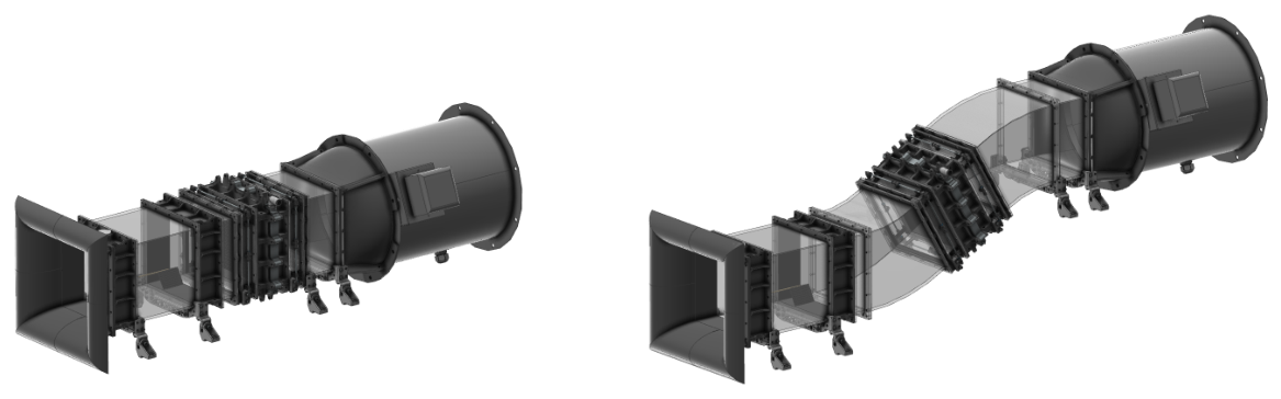
Figure 1. Sketch of the experimental setup of TMTmad with two alternative arrangements. (Left): Straight duct including HEX, fan and transition segments. (Right): System with added bends to study the influence of flow guidance and uniformity of flow inside cooling ducts.
Engproc 133 00105 g001
Figure 2. Images of the experimental setup of TMTmad in the straight-Line configuration. (Left): Frontal view into the system with a 3D-printed Gyroid structure inside. (Right): Side view of the experiment.
Engproc 133 00105 g002
Figure 3. Test set-up in two scenarios: (Left): Experimental setup with axial blower. (Right): TMTmad is attached to the aeroacoustic wind tunnel of the Brandenburg University of Technology Cottbus-Senftenberg.
Engproc 133 00105 g003
Figure 4. Measured heat fluxes in dependence of the air flow Reynolds number for varying volume flow rates and different inlet temperatures of the liquid coolant.
Engproc 133 00105 g004
Figure 5. Heat flux effectiveness Q ˙ / Q ˙ max depending on the air flow Reynolds number for varying volume flow rates and different inlet temperatures of the liquid coolant.
Engproc 133 00105 g005
Figure 6. Air side pressure coefficients of HEX depending on air flow Reynolds number in different cases.
Engproc 133 00105 g006
Table 1. Parameters for the investigated cases labeled as TxxVy, where xx denotes the temperature in °C and y denotes the volume flux in L / min .
T50V2T50V3T50V4T50V5T60V2T60V3T60V4
T H  [°C]50505050606060
V ˙  [L/min]2345234
T60V5T70V2T70V3T70V4T80V2T80V3T80V4
T H  [°C]60707070808080
V ˙  [L/min]5234234
Disclaimer/Publisher’s Note: The statements, opinions and data contained in all publications are solely those of the individual author(s) and contributor(s) and not of MDPI and/or the editor(s). MDPI and/or the editor(s) disclaim responsibility for any injury to people or property resulting from any ideas, methods, instructions or products referred to in the content.