


Abstract
This work investigates the influence of center positioning in Radial Basis Function (RBF) collocation methods for solving two-dimensional structural problems. The study enforces equilibrium using the indefinite equations approach and evaluates different center distributions to assess their impact on solution accuracy and stability. The numerical results are compared against Finite Element Method (FEM) solutions to determine the effectiveness of the tested approaches. The findings provide insights into optimal node placement strategies, improving the reliability and applicability of RBF collocation methods in structural analysis.
1. Introduction
Since the earliest stages of scientific inquiry, mathematicians, engineers, and scientists have sought methods to model and understand the physical world. As models have grown in complexity, purely analytical solutions have often proven either too approximate or entirely insufficient. To address this, increasingly sophisticated strategies have been developed to enable accurate and reliable problem-solving.
In structural and mechanical engineering, the adoption of numerical approaches has been particularly significant since the mid-twentieth century, when the Finite Element Method (FEM) became a standard tool for structural analysis [1], while the Finite Volume Method (FVM) was established in the field of fluid dynamics [2]. Today, the use of numerical simulations based on FEM is ubiquitous in both research and industrial practice, to the extent that it is often taken for granted. This widespread reliance stems from the robustness, scalability, and adaptability of FEM, which has consistently demonstrated its effectiveness across a wide range of engineering applications.
Nonetheless, FEM also presents limitations in certain scenarios. Challenges arise in problems involving discontinuities [3], strongly coupled multiscale effects, or situations where multiple levels of detail are mutually interdependent [4]. Laminated composites provide a paradigmatic example: reliable predictions of stress at the fiber–matrix interface can only be achieved by simulations that extend down to the smallest scale, leading to prohibitive computational demands [5,6]. A key difficulty in such cases lies in the dependence of FEM on computational mesh. The meshing process itself may be resource-intensive, while the mesh can become an obstacle in problems involving evolving discontinuities, such as crack propagation, where remeshing is often required. Similar complications occur in multiphysics problems with large deformations or mutual interactions, where adaptive meshing strategies may significantly increase computational cost [7].
Meshless or meshfree methods have emerged as an attractive alternative to mitigate these issues. By relying solely on nodes or points in the computational domain, they avoid strict dependence on mesh generation [8]. Although the origins of meshless methods can be traced back to the 1970s—most notably to Lucy’s pioneering work in astrophysics [9]—the body of research devoted to these approaches remains relatively modest. Nevertheless, they have been applied across a wide spectrum of scientific and engineering fields and continue to offer promising avenues for addressing problems where traditional FEM-based techniques face fundamental challenges [10]. Several meshfree methods are available in the literature, spanning from Smoothed Particle Hydrodynamics (HPS) [11] to weak-form Galerkin meshfree methods [12]. An important class of meshfree methods is represented by collocation [13]. Through the selection of appropriate collocation or discretization points, meshless collocation methods transform differential and engineering problems into algebraic equations that can be solved more efficiently. In this context, Radial Basis Functions (RBF) led to very successful results [14].
In general, Radial Basis Function (RBF) collocation methods can be broadly divided into two categories: boundary-type and domain-type approaches. The Kansa method [15], which forms the basis of the present study, belongs to the latter class. Although this method has demonstrated remarkable performance in several numerical applications [16], much of the reported progress in the literature has been guided primarily by intuition rather than by rigorous theoretical foundations. Furthermore, RBF-based methods still face significant challenges, including the high computational cost associated with solving the resulting systems and the severe ill-conditioning of the interpolation matrix, which can compromise both stability and accuracy [17].
In this work, we investigate the impact of RBF collocation center placement on the solution of two-dimensional structural problems. Within the proposed framework, equilibrium is enforced in strong form through the governing equations, while boundary conditions are imposed using the Kansa method. Different strategies for distributing collocation centers are examined, ranging from regularly spaced Cartesian layouts to quasi-random arrangements. Particular attention is devoted to local refinement of the RBF center distribution in regions characterized by pronounced stress gradients. Furthermore, a novel strategy is introduced to generate meshless quasi-random point distributions with adaptive refinement near stress concentrations, thereby enhancing the accuracy of the numerical solution without incurring excessive computational cost.
We demonstrate that an appropriate distribution of RBF centers within the domain can achieve a solution quality comparable to that obtained with a much denser discretization, while significantly reducing the associated computational cost.
2. RBF Interpolation
The Kansa method relies on Radial Basis Function (RBF) interpolation. Since their introduction, RBFs have been widely employed as a powerful tool for interpolating scattered data in n-dimensional spaces [18], owing to their ability to reconstruct a continuous analytical function from values known only at a discrete set of source points [19], while exactly satisfying the prescribed constraints.
The accuracy and performance of the interpolation depend on both the selection of the interpolation scheme and the specific type of basis function adopted. These basis functions are typically defined in an n-dimensional space and are formulated as functions of distance—commonly expressed through the Euclidean norm between pairs of points [20]. By prescribing displacements at a set of known locations, the corresponding values at additional points can be recovered, which in turn enables mesh deformation while preserving the overall grid topology [21,22]. In general, the interpolation function can be expressed as a basis function of the form:
where denotes the Radial Basis Function evaluated at the Euclidean norm, and represents a weighting coefficient ensuring that satisfies the prescribed boundary values at the corresponding RBF centers. Enforcing this condition leads to the solution of the RBF problem through a linear system of the form:
Equation (1) can be extended by introducing an additional polynomial term, which enables the exact reproduction of functions belonging to the same polynomial class. This enhancement ensures accuracy not only at the source points but also within the interpolated domain.
The interpolation behavior between prescribed centers, as previously noted, is primarily governed by the choice of the kernel. Radial Basis Function kernels can be broadly classified into two categories: globally supported and compactly supported, depending on whether the function attains nonzero values throughout the domain or vanishes outside a finite support. Representative examples of RBF kernels are reported in Table 1.
Table 1.
Common RBF Kernels.
RBFs have been used in the past across various engineering domains, from the simulation of shape memory polymer-based structures [23] to strain field retrieval for Digital Image Correlation methods [24] and flexible circuit boards [25], shaping optimization using traditional [26] or evolutive approaches [27].
3. Kansa Method
Given the limitations of mesh-based methods previously discussed, particularly the complexity and computational cost associated with mesh generation, considerable research efforts over the past decades have focused on developing meshless alternatives. While many of these approaches rely on Moving Least Squares (MLS) formulations, collocation methods based on RBF have proven capable of solving Partial Differential Equations (PDE) in a genuinely meshless manner. These methods are characterized by their conceptual simplicity and straightforward implementation, both of which stem from the underlying RBF interpolation.
Following the pioneering work of Kansa [15,28], several variants of RBF collocation methods have been proposed, including the Hermite collocation method (HCM) [29], the modified Kansa method (MKM) [30], and the method of particular solutions (MPS) [31], each differing primarily in whether a boundary- or domain-based approach is adopted. In the present work, the standard Kansa method is employed to solve the PDEs of equilibrium in strong form and to enforce boundary conditions in terms of stresses.
In the Kansa formulation, any differential operator can be applied directly to the chosen RBF kernel, provided that the basis function is sufficiently smooth to allow the required differentiability and that it can accurately reproduce the expected physical behavior. This leads to a system analogous to Equation (2), in which a new distance matrix is introduced and differentiated as needed according to the governing PDE. The system is solved by enforcing the prescribed values of the PDEs and of the boundary conditions at the collocation points. The resulting RBF weights can then be used to recover the target fields by applying the appropriately differentiated kernel during the interpolation stage.
Although this approach is elegant, powerful, and straightforward, it is not without drawbacks. The method often results in non-symmetric system matrices, exhibits ill-conditioning for large-scale problems, and may suffer from reduced interpolation quality near boundaries. These limitations have motivated this work and remain an active area of research within the scientific community [14].
Kansa Method for Structural Problems
In this work, as discussed briefly, we solve the structural problem by enforcing the equilibrium in strong form:
Since in all the demonstrations shown here, body forces were absent, Equation (3) for the problem on the plane turns into
According to the Kansa approach and solving the problem by considering the Generalized multiquadric RBF kernel interpolating the displacements, the strain components in case of small deformations can be directly obtained by differentiating the kernel itself. , and can be indeed written as:
As a demonstration, if the plain undifferentiated multiquadric kernel represents the displacements, can be computed by differentiating the kernel along the direction:
For the case of plane stress evaluated in this work, stresses and deformations are linked using the flexibility or compliance matrix in the form:
Several strategies can be adopted to improve the accuracy and robustness of solutions obtained through RBF collocation. One possibility is to modify the choice of the RBF kernel, and so of its differentiated form, as shown in Equation (6), which directly influences both the quality of the approximation and the condition number of the distance matrix . Previous studies have shown that the multiquadric kernel represents a particularly effective choice compared to alternative formulations, especially when differentiation is required, due to its favorable mathematical properties [5]. In addition, when kernels depend on free parameters, these can be tuned and optimized to enhance performance in both interpolation [32] and collocation contexts [33]. Another avenue for improvement involves the use of advanced numerical techniques to solve the collocation system. Several approaches have been proposed to alleviate the severe ill-conditioning typically associated with Kansa-type problems and to reduce the computational burden caused by dense matrices. Methods such as the Partition of Unity Method (PUM) decompose the global problem into a set of local problems, thereby converting dense systems into sparse ones. Other approaches facilitate stabilization through preconditioners or factorization techniques.
In this work, we aim to demonstrate that, in analogy with what is achieved for interpolation [34], an appropriate placement of RBF collocation centers can significantly enhance the quality of the numerical solution. Surprisingly, this approach is scarcely explored in the literature.
4. Validation of the Method
To demonstrate the proposed approach, two 2D problems were tackled using the Kansa method and compared to a FEM solution.
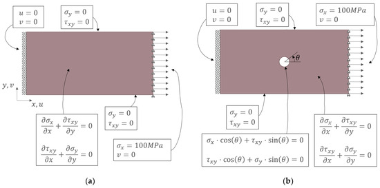
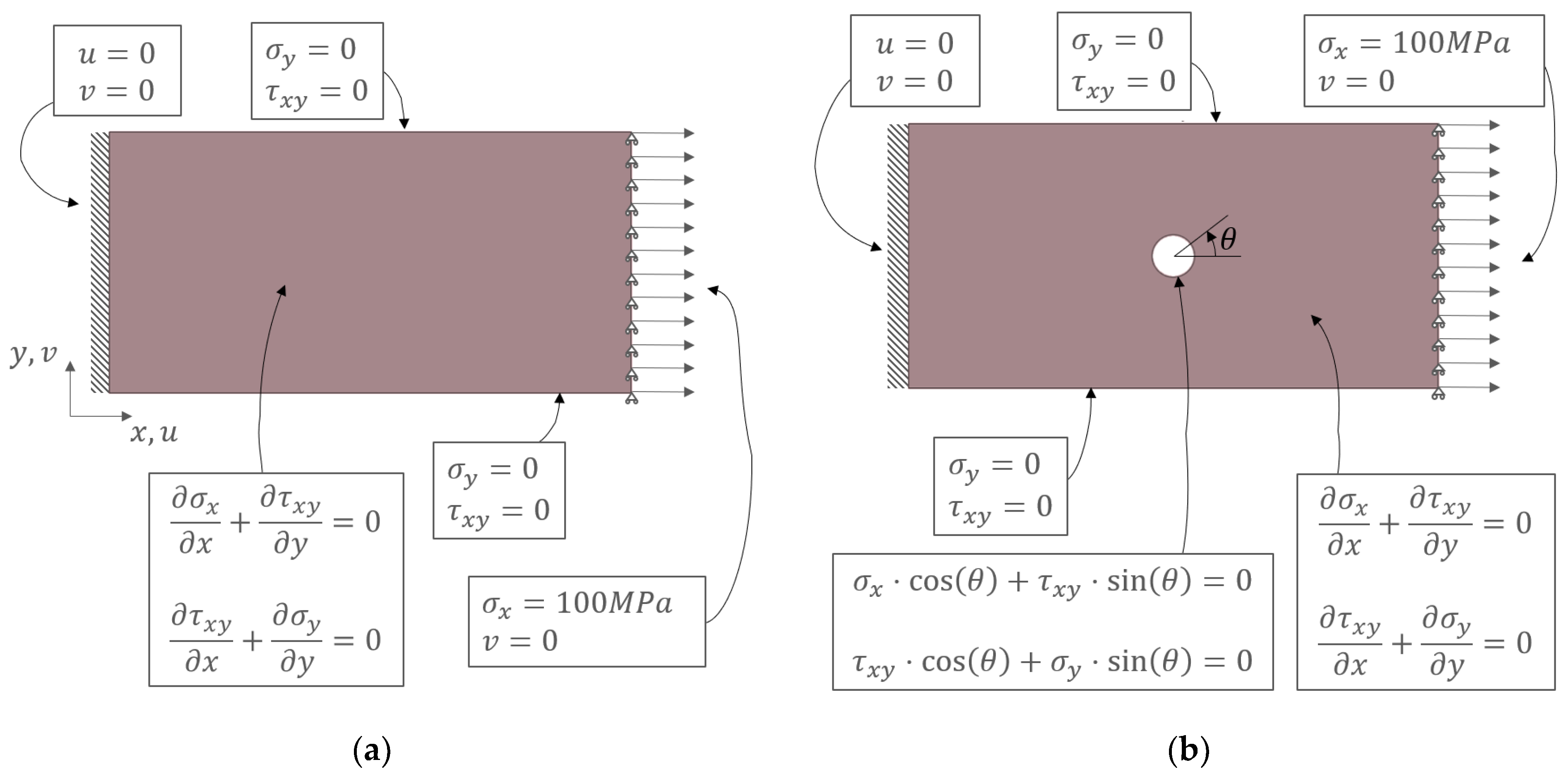
The two benchmark cases considered in this study are illustrated in Figure 1. In both configurations, a plate under plane stress conditions is fully constrained at the left edge and subjected to a prescribed tensile load at the right edge, where vertical displacements are also restrained. All remaining boundaries are left traction-free, including the central hole in case (b).
Figure 1.
Test cases to demonstrate the approach and boundary conditions for the Kansa problem: (a) solid plate; (b) holed plate.
As depicted in Figure 1, where the analytical boundary conditions and the PDEs solved via the Kansa method are also reported, the strong-form equilibrium equations are enforced within the interior domain, while a prescribed load in terms of pressure/stress is applied at the right boundary, together with constraints on the vertical displacement component . At the left boundary, both displacement components and are fixed, whereas all other edges are specified as stress-free, including the boundary of the central hole in test case (b). According to the Kansa method, it is important to also explicitly include in the RBF collocation problem the traction-free boundaries.
For both cases, a Young modulus of 1000 MPa and 0.4 Poisson was employed. Horizontal and vertical dimensions of the plates are 10 mm and 5 mm. For case (b), the hole has a radius of 0.4 mm.
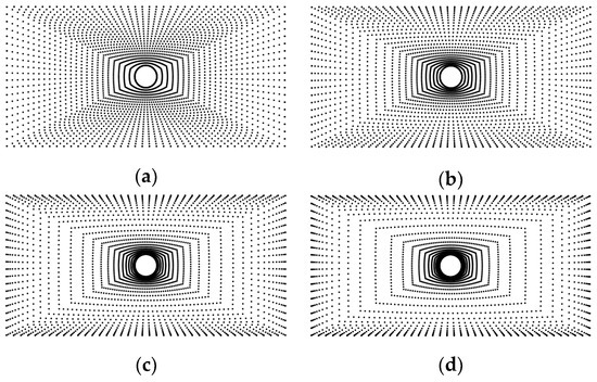
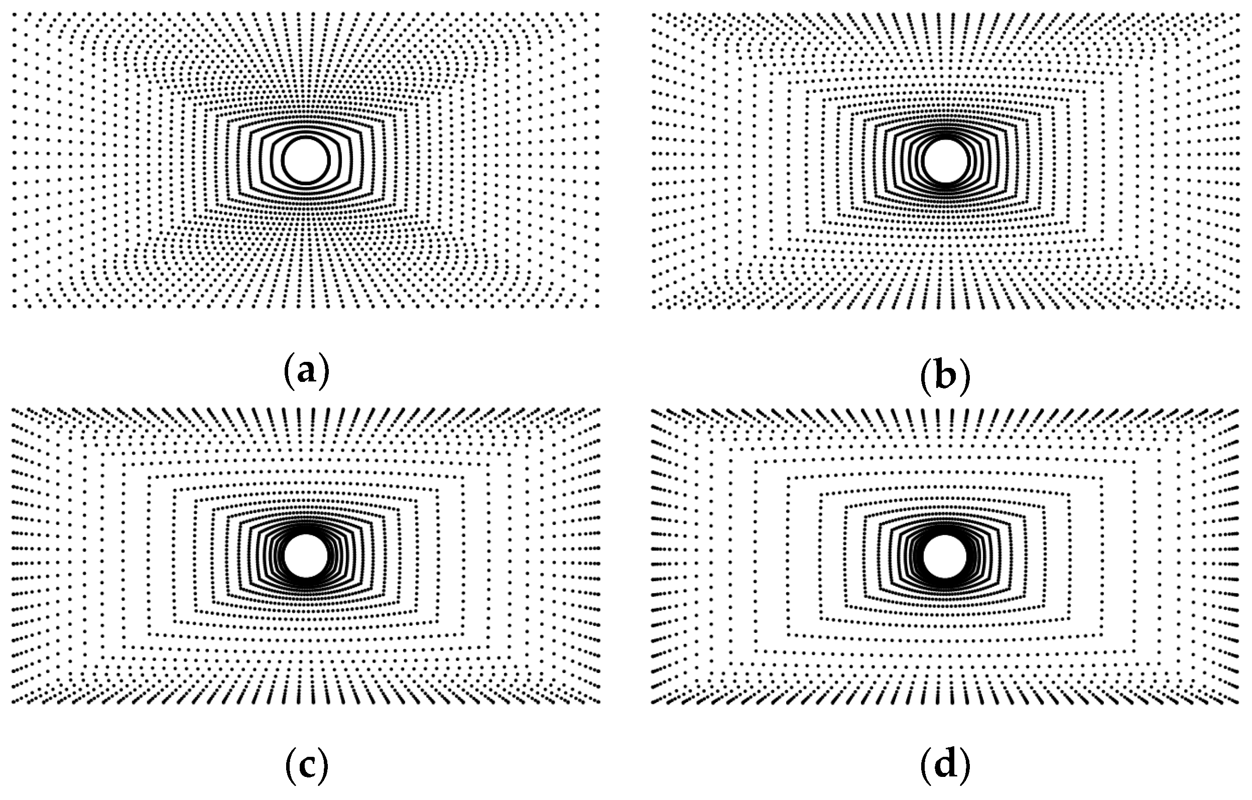
Two strategies for the distribution of collocation centers were examined in both test cases. The first consists of a uniform arrangement, analogous to that obtained through mapped meshing. The second employs a similar layout but introduces a higher density of centers in the vicinity of the boundaries. In this latter approach, the spacing of centers along the edges, and consequently across the surface, is controlled by a bias parameter.
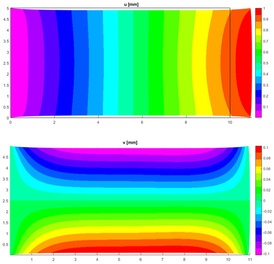
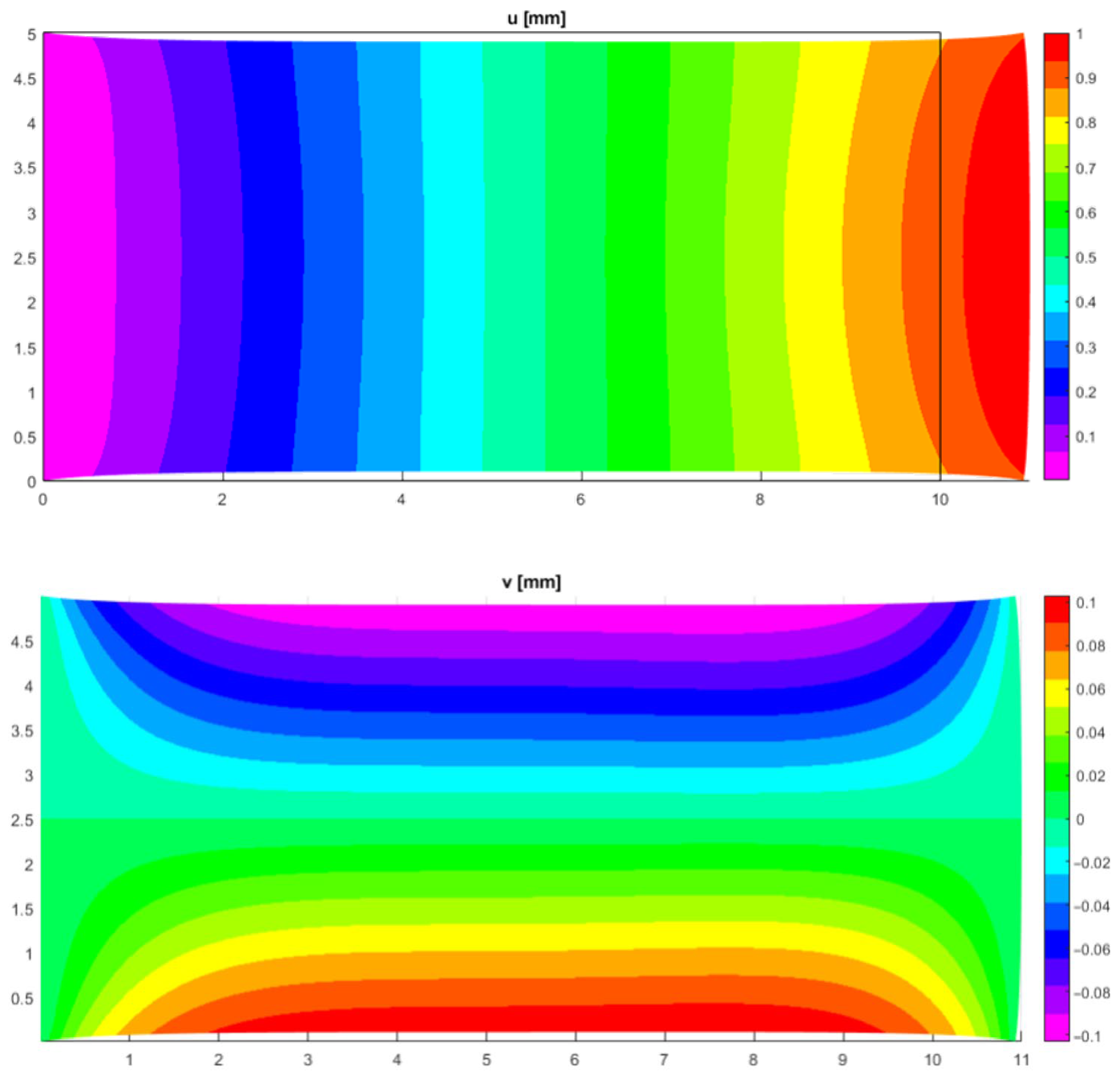
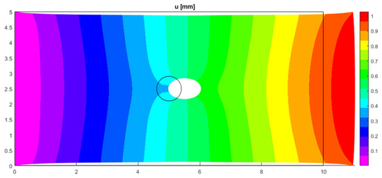
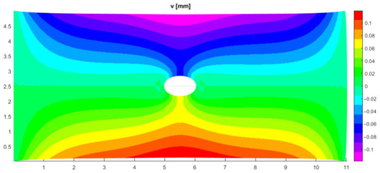
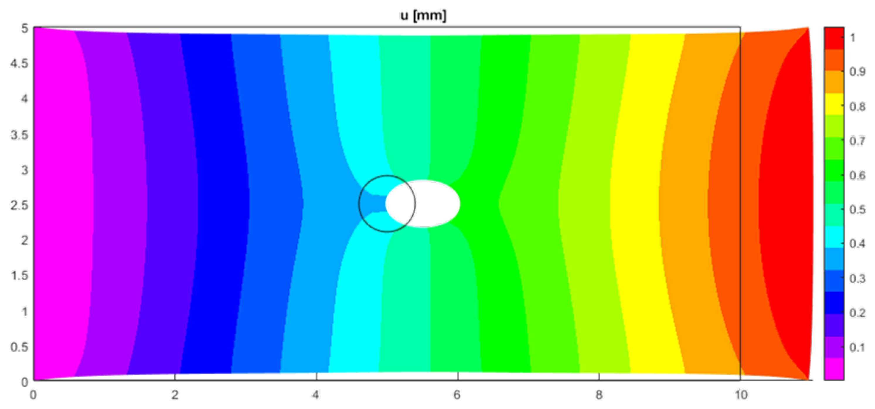
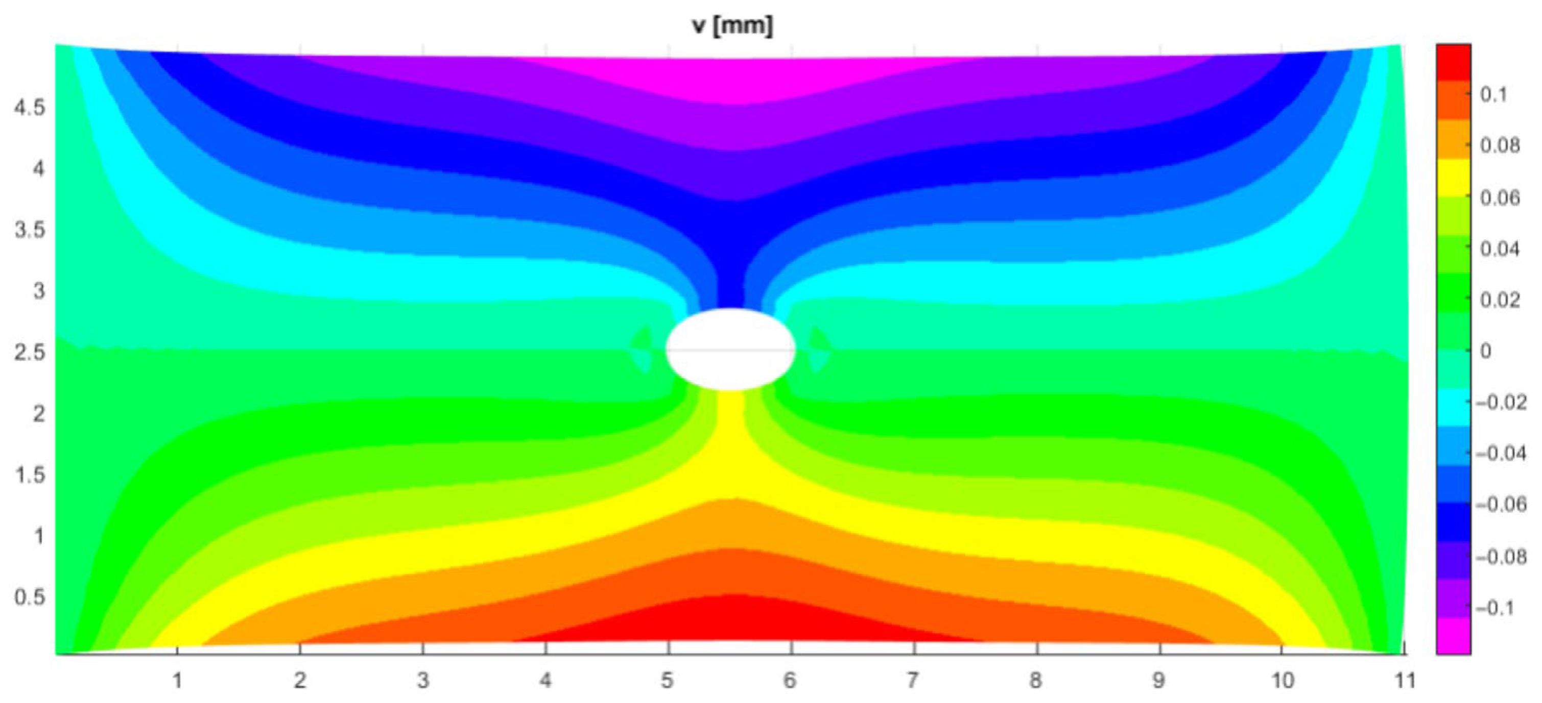
This parameter, as shown in Figure 2, specifies the ratio between the distance of one point to its predecessor and the distance to its successor, thereby governing the degree of clustering near the boundaries. Figure 3 presents the displacement fields and for the solid plate obtained using 3000 uniformly distributed collocation points, while Figure 4 reports the corresponding results for the plate with a central hole.
Figure 2.
Effect of bias parameter on the distribution of centers. RBF centers for the case of 3000 points with varying ratios: (a) ratio = 1; (b) ratio = 1.1; (c) ratio = 1.2; (d) ratio = 1.3.
Figure 3.
Displacements for the solid plate with 3000 uniform collocation points.
Figure 4.
Displacements for the solid plate with 3000 uniform collocation points. On the upper image, the baseline geometry is superimposed on the deformed geometry.
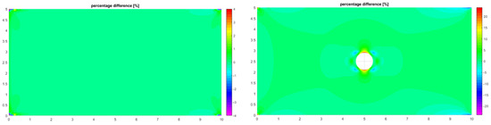
A comparison of the stress component against a high-fidelity FEM reference solution is shown in Figure 5. For the solid plate, the agreement is very good, with a maximum error of 2.3%. In contrast, for the perforated plate, the discrepancies are considerably larger, reaching a maximum error of 34% with respect to the FEM reference.
Figure 5.
Comparison of results using 3000 uniform collocation points with regard to the FEM golden standard. Left: solid plate; right: plate with central hole.
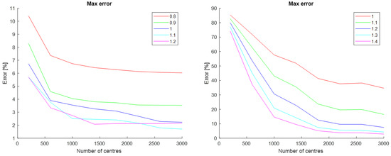
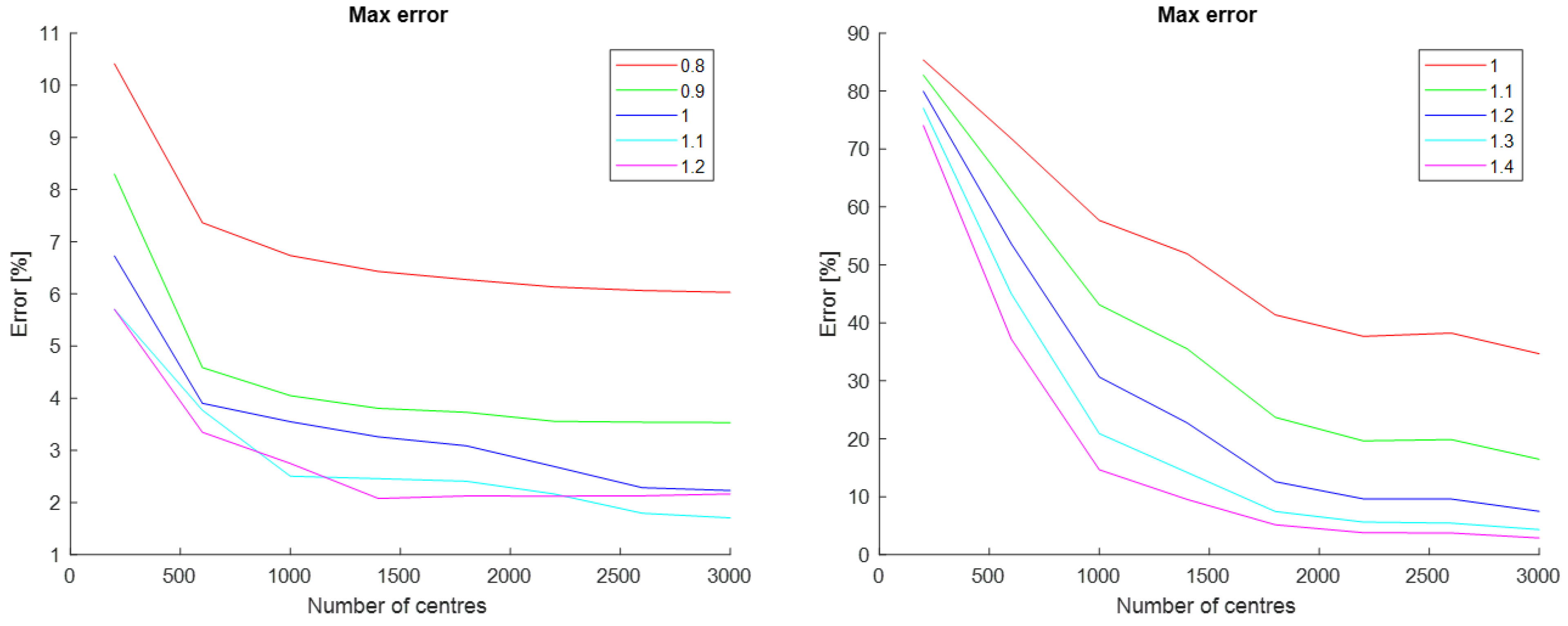
Several combinations of bias values and numbers of collocation centers were investigated, and for each configuration the maximum error relative to the FEM reference solution was computed. The results are summarized in the plots of Figure 6.
Figure 6.
Maximum error with respect to FEM golden standard for solid plate (left) and plate with hole (right).
As expected, increasing the number of centers—thereby reducing their average spacing—leads to a reduction in error with respect to the FEM benchmark. At the same time, introducing a bias factor greater than unity which increases the density of centers near the boundaries results in a significant improvement in accuracy. This effect is particularly pronounced for the perforated plate: the maximum error decreases from 34% with a uniform distribution (bias = 1) to 2.8% with bias = 1.4, while keeping the total number of centers unchanged. These results demonstrate that biasing not only reduces the error for a fixed discretization but also enables comparable accuracy to be achieved with a substantially smaller number of centers.
Although these results are encouraging and clearly demonstrate that increasing the density of collocation points near the boundaries improves the accuracy of the solution, such distribution strategies cannot be considered fully meshless, since they inherently depend on the geometry of the boundaries themself. One of the key advantages of the Kansa collocation method lies in its genuinely meshless nature, but the use of biased point distributions partly undermines this feature, reintroducing a dependence on boundary geometry.
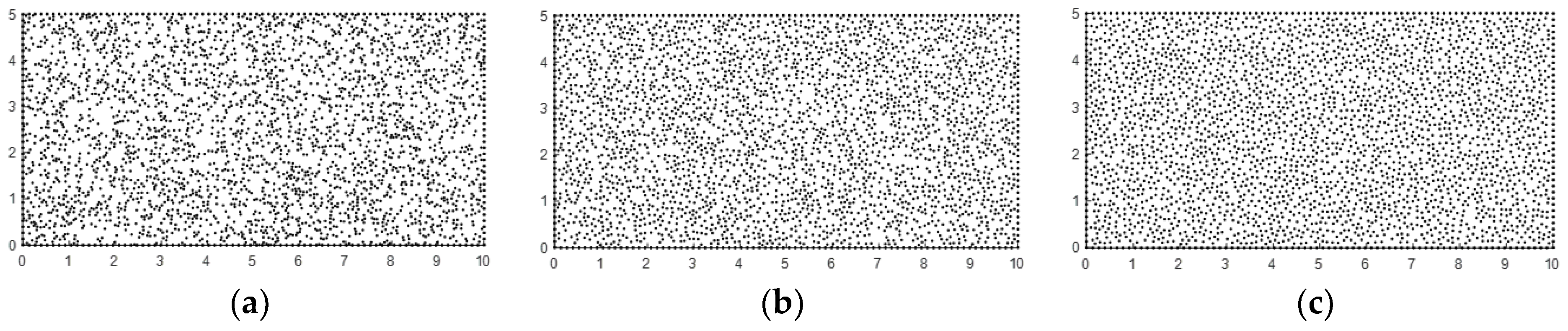
For this reason, we also explored an alternative strategy based on Poisson disk sampling, which generates a pseudo-random distribution of points within the domain. A purely random placement of centers is not a viable option, as it typically results in poor stability and accuracy: the system matrix may become ill-conditioned due to clustering, while gaps in the distribution can lead to irregular domain coverage. In the Poisson disk sampling approach, candidate points are generated randomly but are accepted only if their distance from previously placed points exceeds a prescribed threshold . This procedure ensures both randomness and uniform spacing. The concept is illustrated in Figure 7, where 3000 points are distributed using this pseudo-random technique for different threshold values.
Figure 7.
Poisson disk sampling distribution on the plate domain changing the threshold: (a) = 0.05; (b) = 0.075; (c) = 0.09.
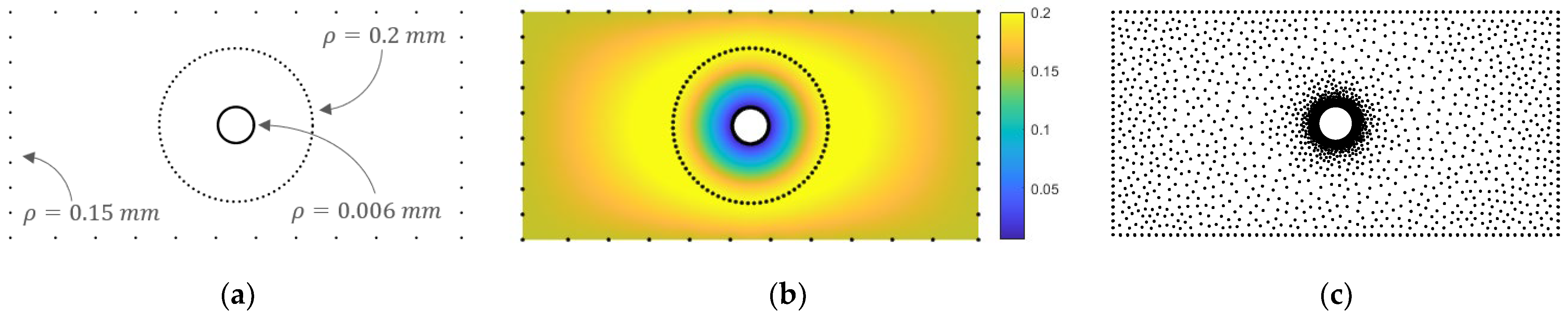
To combine the advantages of pseudo-random distributions with the variable density of collocation centers—previously shown to yield beneficial effects—we developed a fully meshless strategy for adaptive RBF center seeding. In this approach, multiple values of the threshold parameter are prescribed across the domain and interpolated into a continuous RBF field, which defines the boundary conditions for the collocation point generation problem. The pseudo-random distribution algorithm then evaluates each candidate point , accepting it only if its distance from existing points exceeds the locally defined threshold . As a result, the point distribution becomes naturally denser in regions where is smaller and sparser where assumes larger values.
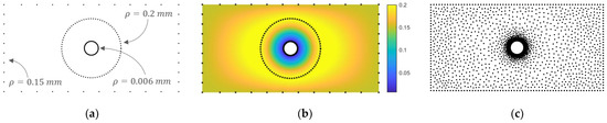
Figure 8 illustrates this concept for the case of the perforated plate. In the meshless configuration shown in (a), the threshold parameter is prescribed with smaller values in the vicinity of the central hole and larger values in regions farther from the boundaries. This yields the threshold field depicted in (b), which in turn generates the collocation point distribution presented in (c) using 3000 points.
Figure 8.
Variable pseudo-random distribution of collocation points. (a) Setup of the collocation point generation problem; (b) RBF field of ; (c) resulting center distribution using the proposed approach.
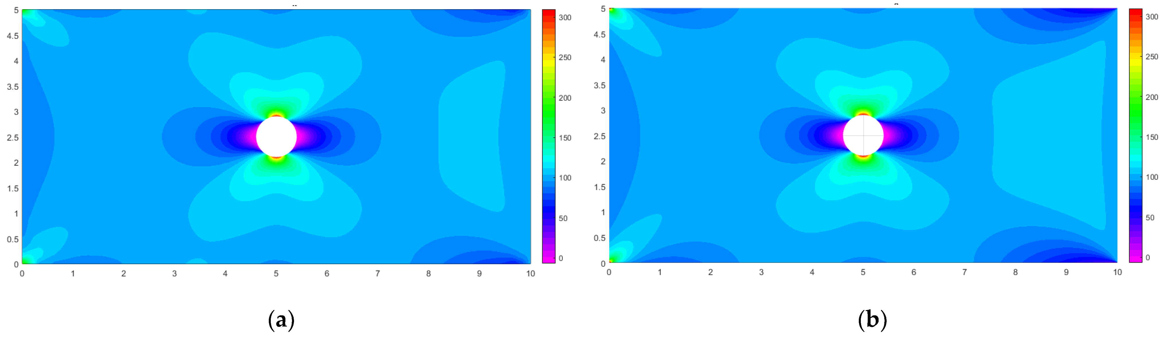
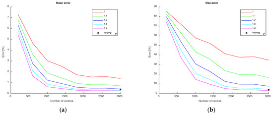
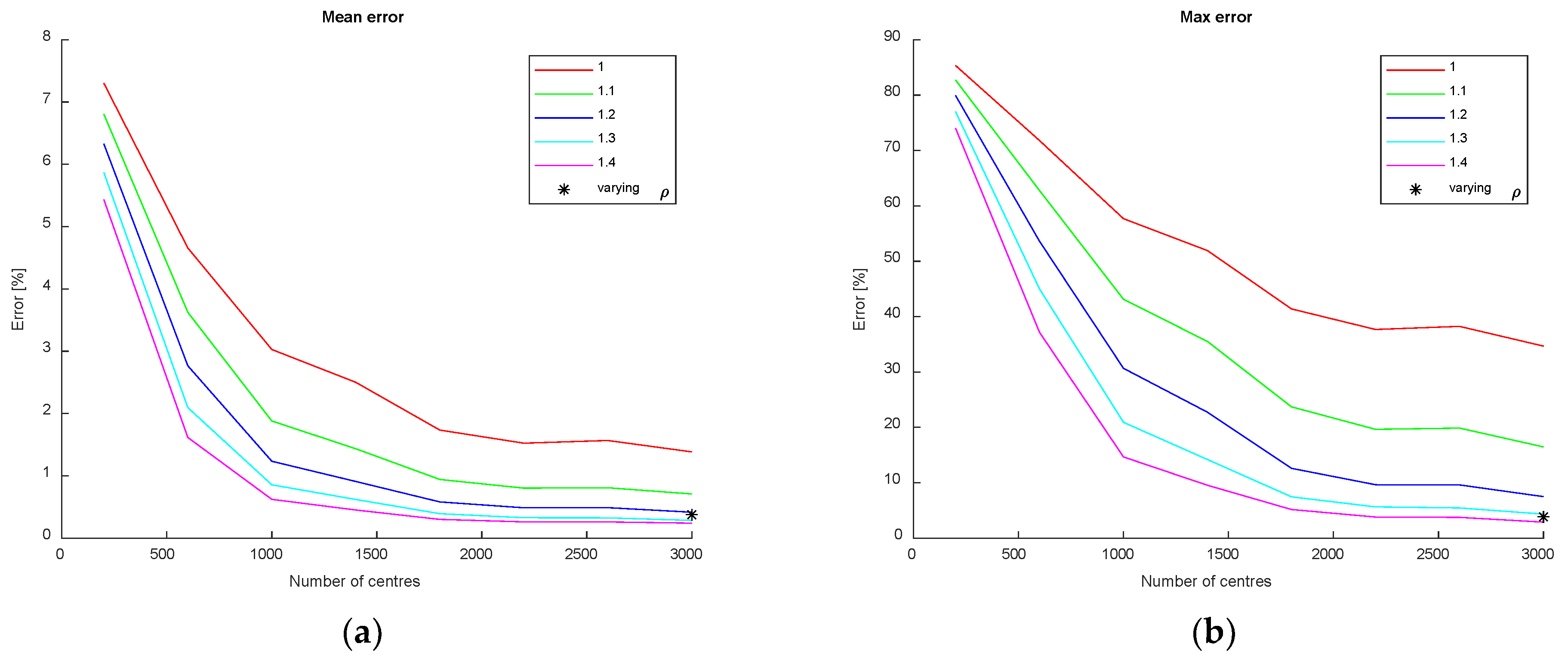
Figure 9 compares the field obtained with the proposed center distribution using 3000 collocation points using the Kansa method (a) against a high-fidelity FEM reference solution with 385,000 nodes (b). The agreement is particularly good in the vicinity of the hole, where the collocation density is higher. In terms of both maximum and mean errors, the results are comparable to those achieved with the same number of collocation points using a biased distribution, as illustrated in Figure 10.
Figure 9.
(a) computed using the proposed method employing 3000 centers and (b) FEM result.
Figure 10.
Mean and maximum error of the proposed approach compared to those obtained using the biased distribution.
Although mean and maximum errors are comparable to those obtained with biased distributions, they are achieved here through a fully meshless approach. This formulation can be extended without effort to more complex geometries or three-dimensional domains for which the construction of a biased distribution would be considerably challenging.
5. Conclusions
In this work, we investigate strategies for improving the accuracy and efficiency of meshless collocation methods based on Radial Basis Functions (RBFs), with particular emphasis on the Kansa method applied to two-dimensional structural problems. Our analysis confirms that the spatial distribution of collocation centers plays a critical role in the quality of the solution.
Initially, biased center distributions were shown to provide significant improvements in accuracy by locally refining the point density near boundaries and stress concentrations. However, such approaches compromise the inherently meshless nature of the method, as the distribution of centers becomes strongly dependent on boundary geometry.
To address this limitation, we proposed and tested a fully meshless strategy based on Poisson disk sampling. By introducing a variable distance threshold interpolated into a continuous RBF field, this method enables adaptive pseudo-random point seeding. The resulting distributions achieve local refinement where needed, while preserving the global meshless character of the formulation.
Numerical results demonstrate that this approach yields accuracy comparable to biased distributions while maintaining full scalability to complex geometries and three-dimensional domains where bias-based techniques would be difficult to implement.
Overall, the proposed methodology highlights the potential of adaptive pseudo-random distributions to enhance the robustness and flexibility of RBF collocation schemes. Future research will focus on extending this framework to more complex problems and on automating the meshless center distribution according to an evolutive approach.
Author Contributions
Conceptualization, C.G.; methodology, C.G.; software, A.C. and C.G.; validation, A.C. and C.G.; formal analysis, C.G.; investigation, A.C. and C.G.; resources, C.G.; data curation, C.G.; writing—original draft preparation, C.G.; writing—review and editing, C.G.; visualization, C.G.; supervision, A.C. and C.G.; project administration, C.G. All authors have read and agreed to the published version of the manuscript.
Funding
This research received no external funding.
Institutional Review Board Statement
Not applicable.
Informed Consent Statement
Not applicable.
Data Availability Statement
The data presented in this study are available upon request from the corresponding author.
Conflicts of Interest
The authors declare no conflict of interest.
References
- Liu, W.K.; Li, S.; Park, H.S. Eighty Years of the Finite Element Method: Birth, Evolution, and Future. Arch. Comput. Methods Eng. 2022, 29, 4431–4453. [Google Scholar] [CrossRef] [Scilit]
- Ferziger, J.H.; Perić, M. Computational Methods for Fluid Dynamics, 3rd ed.; Springer: Berlin/Heidelberg, Germany, 2002. [Google Scholar]
- Legrain, G.; Chamoin, L.; Moës, N. Treatment of nearly-singular problems with the X-FEM. Adv. Model. Simul. Eng. Sci. 2014, 1, 13. [Google Scholar] [CrossRef] [Scilit]
- Weck, M.; Nottebaum, T. Adaptive meshing—Saving computational costs during the optimization of composite structures. Struct. Optim. 1993, 6, 108–115. [Google Scholar] [CrossRef] [Scilit]
- Chiappa, A.; Groth, C.; Biancolini, M.E. A two-scale RBF meshless method for the interface stress retrieval in simply bended and torqued long-fibres laminates. Compos. Sci. Technol. 2023, 234, 110039. [Google Scholar] [CrossRef] [Scilit]
- Helali, H.T.; Grafinger, M. The precision of FEM simulation results compared with theoretical composite layup calculation. Compos. B Eng. 2016, 95, 282–292. [Google Scholar] [CrossRef] [Scilit]
- Shamanskiy, A.; Simeon, B. Mesh deformation techniques in fluid-structure interaction: Robustness, accumulated distortion and computational efficiency. Comput. Mech. 2021, 67, 583–600. [Google Scholar] [CrossRef] [Scilit]
- Chen, J.S.; Hillman, M.; Chi, S.W. Meshfree methods: Progress made after 20 years. J. Eng. Mech. 2017, 143, 04017001. [Google Scholar] [CrossRef] [Scilit]
- Lucy, L.B. A numerical approach to the testing of the fission hypothesis. Astron. J. 1977, 82, 1013–1024. [Google Scholar] [CrossRef] [Scilit]
- Jiang, W.; Gao, X. Review of Collocation Methods and Applications in Solving Science and Engineering Problems. Comput. Model. Eng. Sci. 2024, 140, 41–76. [Google Scholar] [CrossRef] [Scilit]
- Gingold, R.A.; Monaghan, J.J. Smoothed particle hydrodynamics: Theory and application to non-spherical stars. Mon. Not. R. Astron. Soc. 1977, 181, 375–389. [Google Scholar] [CrossRef] [Scilit]
- Liu, W.K.; Jun, S.; Zhang, Y.F. Reproducing kernel particle methods. Int. J. Numer. Methods Fluids 1995, 20, 1081–1106. [Google Scholar] [CrossRef] [Scilit]
- Liu, G.R.; Gu, Y.T. An Introduction to Meshfree Methods and Their Programming; Springer Science & Business Media: Berlin/Heidelberg, Germany, 2005. [Google Scholar]
- Chen, W.; Fu, Z.J.; Chen, C.S. Recent Advances in Radial Basis Function Collocation Methods; Springer: Berlin/Heidelberg, Germany, 2014. [Google Scholar]
- Kansa, E.J. Multiquadrics—A scattered data approximation scheme with applications to computational fluid-dynamics-I: Surface approximations and partial derivative estimates. Comput. Math. Appl. 1990, 19, 127–145. [Google Scholar] [CrossRef] [Scilit]
- Cheung, K.C.; Ling, L.; Schaback, R. H2-convergence of least-squares kernel collocation methods. SIAM J. Numer. Anal. 2018, 56, 614–633. [Google Scholar] [CrossRef] [Scilit]
- Chantasiriwan, S. Investigation of the use of radial basis functions in local collocation method for solving diffusion problems. Int. Commun. Heat. Mass. Transf. 2004, 31, 1095–1104. [Google Scholar] [CrossRef] [Scilit]
- Davis, P.J. Interpolation and Approximation; Dover Publications: Mineola, NY, USA, 1975. [Google Scholar]
- Hardy, R.L. Multiquadric equations of topography and other irregular surfaces. J. Geophys. Res. 1971, 76, 1905–1915. [Google Scholar] [CrossRef] [Scilit]
- de Boer, A.; van der Schoot, M.S.; Bijl, H. Mesh deformation based on radial basis function interpolation. Comput. Struct. 2007, 85, 784–795. [Google Scholar] [CrossRef] [Scilit]
- Beckert, A.; Wendland, H. Multivariate interpolation for fluid-structure-interaction problems using radial basis functions. Aerosp. Sci. Technol. 2001, 5, 125–134. [Google Scholar] [CrossRef] [Scilit]
- Biancolini, M.E. Fast Radial Basis Functions for Engineering Applications; Springer: Cham, Switzerland, 2018. [Google Scholar] [CrossRef] [Scilit]
- Groth, C.; Chiappa, A.; Biancolini, M.E.; Scalet, G. A computational approach for the simulation of shape memory polymer-based structures via finite elements and mesh morphing. Smart Mater. Struct. 2025, 34, 5049. [Google Scholar] [CrossRef] [Scilit]
- Groth, C.; Chiappa, A.; Porziani, S.; Biancolini, M.E.; Marotta, E.; Salvini, P. A post-processing method based on radial basis functions for the fast retrieval of the strain field in digital image correlation methods. Materials 2022, 15, 7936. [Google Scholar] [CrossRef] [Scilit]
- Groth, C.; Chiappa, A.; Porziani, S.; Salvini, P.; Biancolini, M.E. An RBF meshless approach to evaluate strain due to large displacements in flexible printed circuit boards. Micromachines 2022, 13, 1163. [Google Scholar] [CrossRef] [Scilit]
- Groth, C.; Chiappa, A.; Biancolini, M.E. First thermo-structural vacuum barrier design for the EU DEMO feeders. Fusion. Eng. Des. 2025, 214, 114905. [Google Scholar] [CrossRef] [Scilit]
- Porziani, S.; Groth, C.; Waldman, W.; Biancolini, M.E. Automatic shape optimisation of structural parts driven by BGM and RBF mesh morphing. Int. J. Mech. Sci. 2020, 189, 105976. [Google Scholar] [CrossRef] [Scilit]
- Kansa, E.J. Multiquadrics—A scattered data approximation scheme with applications to computational fluid-dynamics—II: Solutions to parabolic, hyperbolic and elliptic partial differential equations. Comput. Math. Appl. 1990, 19, 147–161. [Google Scholar] [CrossRef] [Scilit]
- Fasshauer, G.E. Solving partial differential equations by collocation with radial basis functions. In Surface Fitting and Multiresolution Methods; LeMéhauté, A., Schumaker, L.L., Eds.; Vanderbilt University Press: Nashville, TN, USA, 1997; pp. 131–138. [Google Scholar]
- Fedoseyev, A.L.; Friedman, M.J.; Kansa, E.J. Improved multiquadric method for elliptic partial differential equations via PDE collocation on the boundary. Comput. Math. Appl. 2002, 43, 439–455. [Google Scholar] [CrossRef] [Scilit]
- Chen, C.S.; Fan, C.M.; Wen, P.H. The method of particular solutions for solving certain partial differential equations. Numer. Methods Partial. Differ. Equ. 2012, 28, 506–522. [Google Scholar] [CrossRef] [Scilit]
- Rippa, S. An algorithm for selecting a good value for the parameter c in radial basis function interpolation. Adv. Comput. Math. 1999, 11, 193–210. [Google Scholar] [CrossRef] [Scilit]
- Chiappa, A.; Groth, C.; Reali, A.; Biancolini, M.E. A stress recovery procedure for laminated composite plates based on strong-form equilibrium enforced via the RBF Kansa method. Compos. Struct. 2020, 244, 112292. [Google Scholar] [CrossRef] [Scilit]
- Iske, A. Optimal Distribution of Centers for Radial Basis Function Methods; Technical Report M0004; Technische Universität München: Munich, Germany, 2000. [Google Scholar]


Disclaimer/Publisher’s Note: The statements, opinions and data contained in all publications are solely those of the individual author(s) and contributor(s) and not of MDPI and/or the editor(s). MDPI and/or the editor(s) disclaim responsibility for any injury to people or property resulting from any ideas, methods, instructions or products referred to in the content. |
© 2026 by the authors. Licensee MDPI, Basel, Switzerland. This article is an open access article distributed under the terms and conditions of the Creative Commons Attribution (CC BY) license.