Proceeding Paper

Towards Biocompatible and Sustainable Flexible RFID Tags Using Screen-Printed PEDOT:PSS †
1
Pervasive Electronics Advanced Research Laboratory (PEARL), Department of Electronics and Computer Technology, Faculty of Sciences, University of Granada, 18071 Granada, Spain
2
Green RF-Enabled Electronics Lab, University of Glasgow, Glasgow G12 8QQ, UK
*
Author to whom correspondence should be addressed.
Presented at the International Conference on Responsible Electronics and Circular Technologies (REACT 2025), Glasgow, UK, 11–12 November 2025.
Eng. Proc. 2026, 127(1), 20; https://doi.org/10.3390/engproc2026127020

Published: 18 May 2026

Abstract

This work presents the design and implementation of a flexible RFID tag based on a biocompatible and environmentally friendly conductive polymer, PEDOT:PSS, which is deposited onto a polyimide/fabric substrate using screen-printing techniques. The complete system consists of a dipole antenna based on PEDOT:PSS and a compact inductive metallic loop on a separate flexible printed circuit board (PCB) designed to match the capacitive impedance of a commercial RFID chip. The modular architecture, with the integrated circuit (IC) mounted on a reusable PCB substrate, shows efficient power transfer while allowing for easy disassembly, recycling, and consequently circularity of the PEDOT:PSS antenna and IC. By leveraging biocompatible materials and additive manufacturing processes, the proposed approach contributes to the advancement of sustainable and low-impact wireless technologies, addressing environmental concerns in next-generation electronics.

1. Introduction

Wearable devices have become an essential part of modern life, seamlessly integrating technology into everyday activities and attire. Despite this potential, most wearable devices available today are limited to specialized designs such as wristbands for fitness and health tracking, smart watches, and rings. Among the various platforms for wearable technologies, the interest in flexible electronics for body-implantable devices, medical applications, and wireless power transfer has grown significantly over the past decade, largely driven by advances in wearable technology and the Internet of Things (IoT) [1].
Alongside the rapid adoption of electronic devices for health and activity monitoring, increasing environmental concerns regarding electronic waste and carbon emissions have strengthened the need for sustainable alternatives. This has encouraged the development of wearable technologies that combine advanced functionality with environmentally responsible design, enabling scalability without increasing the ecological footprint. In this context, the exploration of biocompatible, organic, and low-waste conductive materials has gained increasing attention [2,3].
Within this framework, we introduce a conductive polymer, PEDOT:PSS-based textile antenna, fabricated using screen-printing techniques, coupled to an RFID tag through a multi-stacking process [4,5]. The proposed approach enables large-scale production of textile antennas while promoting sustainability and reusability. Both the RFID tag and the antenna can be recycled and repurposed, which significantly reduces the carbon footprint. Specially, ICs represent a major challenge for the recycling and reuse of electronic components, which constitutes a key factor to consider when performing a life cycle assessment (LCA) of electronic devices [6,7,8]. Furthermore, the designed PEDOT:PSS-based antenna may be reused for other applications within its design frequency band, such as electromagnetic energy harvesting, by simply coupling a new flexible PCB.

2. RFID Tag Design

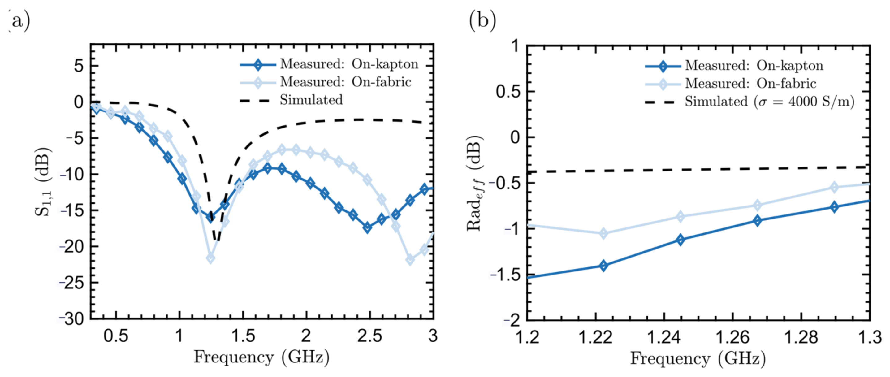
Figure 1 presents a general schematic of the proposed RFID tag design. It comprises a dipole antenna, which is inductively coupled to the RFID chip; the antenna is matched for an off-the-shelf, high-sensitivity RFID IC, the SL3S1204 (NXP Semiconductors, Eindhoven, The Netherlands) through a resonator, designed for conjugate impedance matching with the RFID chip. PCB1 includes the dipole antenna, which captures electromagnetic energy from the surrounding environment to power the RFID tag and radiates the modulated signal. The antenna is fabricated using PEDOT:PSS through screen-printing of a thick film on flexible polyimide substrates (DuPont Kapton® films, Dupont de Nemours, Inc., Wilmington, DE, USA) and on fabric, achieving conductivities in the range of 5 to 15 × 103 S/m at sub-gigahertz frequencies. The antenna, with its coupled Flexible PCB feed, has been optimized to match the real part of the RFID tag input impedance, which is equal to 14.5 Ω at the design frequency of 868 MHz. Figure 2a shows the S11 results obtained from both simulations and experimental measurements of the prototype dipole antennas fabricated on fabric and polyimide substrates. The observed lower reflection coefficient on fabric is due to the lower sheet resistance achieved. Figure 2b shows the estimated radiation efficiency (relative to equivalent copper dipole antenna, based on input impedance comparison) of the antenna based on PEDOT:PSS.
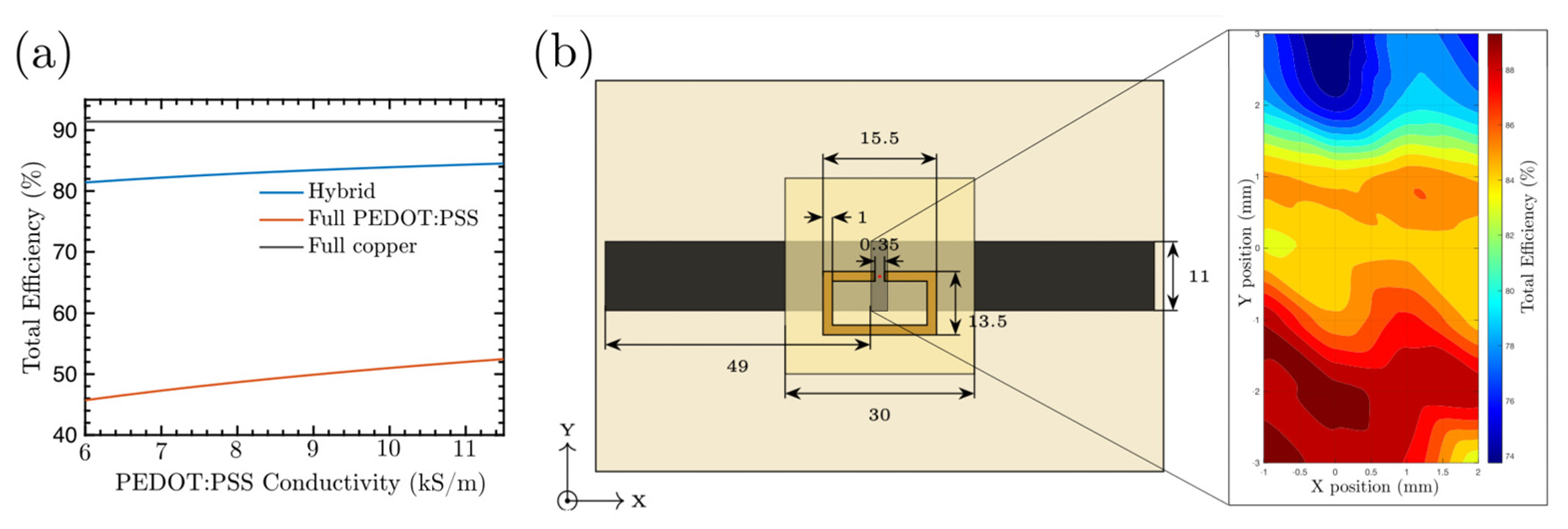
The RFID IC is designed for inclusion on a PCB2 and is coupled to the antenna by means of a resonator. With a trace width of 1 mm and area of 13.5 × 15.5 mm2, the resonator inductively couples the field induced by the dipole antenna and enables conjugate matching by introducing a positive reactance equivalent to the capacitive input impedance of the RFID tag (exemplary Im{Z} = −j293 Ω at the design frequency). The overall efficiency of the system, defined as the fraction of power delivered to the RFID chip considering the reflection coefficient ΓRFID, is shown in Figure 3a as a function of PEDOT:PSS conductivity. Comparative results for a fully PEDOT:PSS-based design (dipole and coil) and a full-copper reference design are also presented. To ensure the prototype is reusable, washable, and modular, while allowing for independent testing of the antenna and straightforward fabrication via screen-printing, both PCBs are manufactured separately and aligned manually. Figure 3b shows the variation in the total efficiency of the system as a function of the position at which the manual alignment of the resonator is performed (assuming a PEDOT:PSS conductivity of 12 × 103 S/m). By manufacturing the system on two separate printed circuit boards, the flexible antenna made from PEDOT:PSS can be reused for other applications, and allows for the reuse of the most challenging element to recycle, namely the IC attached to the RFID tag [7]. This modular approach reduces the total number of PCBs required, contributing significantly to minimizing e-waste.

3. Results

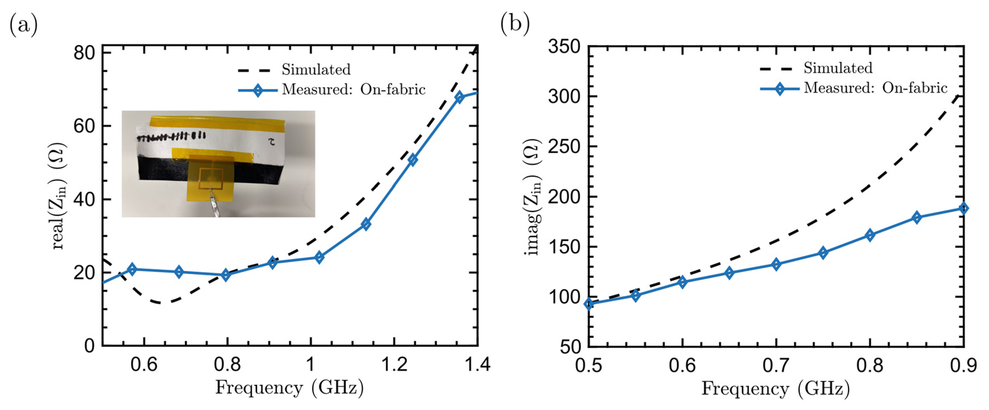
To verify the proper operation of the proposed PCB stack and its conjugate matching to the RFID tag, the input impedance of the complete system was evaluated to determine whether a direct conjugate match to the IC could be achieved at the frequency of interest. This condition ensures maximum power transfer to the RFID tag and optimal backward radiation efficiency. Figure 4 presents the measured real and imaginary components of the system input impedance, along with the expected values achieved with CST Studio simulations. The inset in the figure displays the fabricated device on a fabric substrate. The alignment between the two PCBs was performed manually using TPU-TE-11C hot-melt adhesive. Measurements were carried out with differential probes soldered to the resonator terminals at the position designated for the RFID IC.

4. Conclusions

This work presents the implementation of a stacked, multi-layered structure for the design of flexible, wearable, and bio-compatible RFID tags. This approach offers a promising path toward the development of sustainable and adaptable RFID systems for future applications in wearable electronics, biomedical devices, and environmentally responsible technologies. The use of a stacked, modular configuration consisting of two PCBs enables the reuse of the largest environmental impact component, the IC, by detaching it, allowing its subsequent recycling. Furthermore, the PEDOT:PSS-based antenna can be directly incorporated into other wearable platforms, such as rectifying circuits operating within the same frequency band, by simply coupling the corresponding rectifier stage. The proposed stack has been validated for a complex-impedance chip and screen-printed biocompatible PEDOT:PSS conductive ink. The results demonstrate a simulated total radiation efficiency greater than 81% across the entire range of conductivities studied. Experimental validation was carried out on prototypes fabricated on polyimide and fabric substrates, confirming the potential for effective conjugate matching based on RFID chip impedances.

Author Contributions

Conceptualization., F.P. and M.W.; methodology, M.G.-P. and F.P.; validation, M.G.-P., B.K. and M.W.; formal analysis, M.G.-P., F.G.R., F.P. and M.W.; investigation, M.G.-P.; data curation, M.G.-P. and B.K.; writing—original draft preparation, M.G.-P., F.G.R., F.P. and M.W.; writing—review and editing, M.G.-P.; supervision, F.G.R., F.P. and M.W.; project administration, F.G.R., F.P. and M.W.; funding acquisition, F.G.R., F.P. and M.W.;. All authors have read and agreed to the published version of the manuscript.

Funding

This work is supported by the research projects PID2023-148323OA-I00 COMPOSTRONICS and PID2023-150162OB-I00 ADAGE funded by MICIU/AEI/10.13039/501100011033 and by FEDER, UE; the UK EPSRC through grants EP/Y002008/1 and EP/W025752/1, and the UKRI Green Economy Theme UKRI240: REACT; M. García-Palomo acknowledges the grant PREP2023-001936 funded by MCIU/AEI/10.13039/501100011033 and FSE+.

Institutional Review Board Statement

Not applicable.

Informed Consent Statement

Not applicable.

Data Availability Statement

The data supporting the conclusions of this article will be made available by the authors on request.

Conflicts of Interest

The authors declare no conflicts of interest.

References

  1. Moulod, M.; Dontha, B.; Balbaugh, S.; Li, J.; Miranda, F.; Kiourti, A.; Hoelzle, D.J. Highly Conductive Biomaterial for the Safe Printing of Wireless Biosensors and Antennas Inside the Body. ACS Appl. Mater. Interfaces 2025, 17, 29424–29436. [Google Scholar] [CrossRef] [PubMed]
  2. Sourkouhi, Z.S.; AlHourani, J.; Mostaccio, A.; Marrocco, G.; Gogotsi, Y.; Zarifi, M.H. Paper-Based RFID Tag using MXene Towards Sustainable IOT. In Proceedings of the EuCAP, Stockholm, Sweden, 30 March–4 April 2025. [Google Scholar] [CrossRef]
  3. Peñas-Núñez, S.J.; Mecerreyes, D.; Criado-Gonzalez, M. Recent Advances and Developments in Injectable Conductive Polymer Gels for Bioelectronics. ACS Appl. Bio Mater. 2024, 7, 7944–7964. [Google Scholar] [CrossRef] [PubMed]
  4. Yuk, H.; Lu, B.; Lin, S.; Qu, K.; Xu, J.; Luo, J.; Zhao, X. 3D printing of conducting polymers. Nat. Commun. 2020, 11, 1604. [Google Scholar] [CrossRef] [PubMed]
  5. Guerchouche, K.; Herth, E.; Calvet, L.E.; Roland, N.; Loyez, C. Conductive polymer based antenna for wireless green sensors applications. Microelectron. Eng. 2017, 182, 46–52. [Google Scholar] [CrossRef]
  6. Wagih, M.; Bainbridge, A.; Alsulami, B.; Kettle, J. Environmental Life-Cycle Assessment (LCA) of Wireless RF Systems: A Comparative Sustainability Analysis and a Microwave Engineers’ Guide to LCA. IEEE J. Microw. 2024, 4, 987–1000. [Google Scholar] [CrossRef]
  7. Pirson, T.; Delhaye, T.P.; Pip, A.G.; Le Brun, G.; Raskin, J.-P.; Bol, D. The Environmental Footprint of IC Production: Review, Analysis, and Lessons From Historical Trends. IEEE Trans. Semicond. Manuf. 2022, 36, 56–67. [Google Scholar] [CrossRef]
  8. Rahmani, H.; Shetty, D.; Wagih, M.; Ghasempour, Y.; Palazzi, V.; Carvalho, N.B.; Correia, R.; Costanzo, A.; Vital, D.; Alimenti, F.; et al. Next-Generation IoT Devices: Sustainable Eco-Friendly Manufacturing, Energy Harvesting, and Wireless Connectivity. IEEE J. Microw. 2023, 3, 237–255. [Google Scholar] [CrossRef]
Figure 1. PEDOT:PSS RFID tag. (a) Top and lateral views of the full PCB stack (dimensions are expressed in mms). The reusable ICs are placed on PCB2. (b) Equivalent circuit including reflection coefficients and coupling between PCBs. (c) Modular full-stack PCB flow chart.
Engproc 127 00020 g001
Figure 2. (a) Reflection coefficient of the PEDOT:PSS-based dipole antenna. (b) Estimated radiation efficiency of the antenna fabricated on polyimide and fabric substrates.
Engproc 127 00020 g002
Figure 3. (a) Total efficiency of the proposed RFID tag design as a function of PEDOT:PSS conductivity. The graph compares the proposed hybrid structure with PEDOT:PSS-based PCB1 and copper-based PCB2. (b) Total efficiency as a function of PCB2 position. The left panel shows the top-view layout of the proposed RFID tag, with the zoomed-in region (highlighted in gray) indicating the scanned area.
Engproc 127 00020 g003
Figure 4. Differential input impedance of the complete RFID tag including both PCB1 and PCB2. (a) Simulated (dashed line) and measured (symbols) real component of the input impedance. The inset shows the prototype with PCB1 fabricated on a fabric substrate. (b) Simulated (dashed line) and measured (symbols) imaginary component of the input impedance.
Engproc 127 00020 g004
Disclaimer/Publisher’s Note: The statements, opinions and data contained in all publications are solely those of the individual author(s) and contributor(s) and not of MDPI and/or the editor(s). MDPI and/or the editor(s) disclaim responsibility for any injury to people or property resulting from any ideas, methods, instructions or products referred to in the content.