Proceeding Paper

Dynamic Modelling of a Metal Hydride Reactor During Discharge Through Artificial Neural Network Regression †
1
Department of Chemical, Metallurgical and Materials Engineering, Tshwane University of Technology, Staatsartillerie Road, Pretoria West, Pretoria 0183, South Africa
2
HySA Systems, South African Institute for Advanced Materials, University of the Western Cape, Robert Sobukwe Road, Bellville 7535, South Africa
*
Author to whom correspondence should be addressed.
Presented at the 4th International Electronic Conference on Processes, 20–22 October 2025; Available online: https://sciforum.net/event/ECP2025.
Eng. Proc. 2025, 117(1), 70; https://doi.org/10.3390/engproc2025117070
Published: 20 March 2026
(This article belongs to the Proceedings of The 4th International Electronic Conference on Processes)

Abstract

With hydrogen as a clean but hazardous energy carrier, solid-state hydrogen storage in the form of a metal hydride has come forth as a safe and low-pressure storage solution with competitive volumetric energy density. This paper reports the modelling of a metal hydride reactor during its discharge state using neural network regression. This was done by generating a validated finite element model of the reactor, which was then used to generate dynamic operational data based on the desired pressure outlet and heating fluid temperature as independent variables. The best-performing neural network model validation using the experimentally observed data achieved a regression coefficient of 0.99 and a mean squared error of less than 10−4. This predictive model, with further refinement, can be implemented to allow for predictive control, which has always been a challenge through conventional means due to the batch nature of the system. Moreover, the hydrogen concentration as stored in a solid-state measurement would be too expensive for industrial applications.

1. Introduction

Solid-state hydrogen storage refers to the storage of hydrogen in a solid form, particularly through bulk absorption to form metal hydrides. These metal hydrides decompose during heating to release the stored hydrogen. This technology partially addresses the challenges associated with liquid and gas phase storage [1,2,3,4,5]. Furthermore, solid-state hydrogen storage has a very limited environmental impact, as reported by Costamagna et al. [6].
This can be seen in studies by Baldissin et al., Peng et al., and Chibani et al. [7,8,9]. The implementation of the finned heat sinks in a hydride reactor led to superior cooling compared to a reactor that did not have a heat transfer-aided design. Generally, the design of the metal hydride reactor is based on the heat transfer enhancement of the bed. As such, two common variants exist: first, with heat transfer from the outside, and second, with heat transfer from the inside [10,11,12].
A comprehensive literature review on metal hydride reactor design was published by Cui et al. [13], considering heat-sink and various internal cooling designs. Specifically, the internal configurations of radial tubes, helical tubes, and straight pipe heat exchangers were considered and compared. However, there is a clear lack of analysis on designs using both a cooling jacket and internal cooling. Similarly, there is a clear knowledge gap concerning the effects of scaling reactor diameter with internal cooling setups.
Additionally, the studies reviewed by Cui et al. [13] did not consider the trade-off of consuming some of the overall reactor volume with heat exchangers, lowering the effective bed volume and, ultimately, the capacity of the reactor. Lui et al. [14] did report the effects of the tube pitch of the internal straight pipe heat exchangers, albeit only for a singular pipe size, and there has not been a significant contribution to this area since.
Conventional control systems require a feedback approach that measures responses and adjusts accordingly. Alternatively, control systems require predictive control, which needs to be able to predict changes in the response parameters with changes in the input parameters. Solid-state hydrogen storage poses a unique challenge for control systems, being a complex batch system with changes being felt after a long delay. This is compounded by the cost of sensors that can measure hydrogen concentration in a solid state, which are too expensive to be economically feasible. Thus, the ability to design an effective control system around a metal hydride-based hydrogen storage system requires a predictive model to be referenced by the control system [15].

2. Method

The experimental equipment and experimental data necessary to validate this study were supplied by HySA-Systems under the umbrella of the University of the Western Cape [16]. Figure 1 presents a schematic diagram of the experimental setup filled with LaNi4.9Sn0.1 hydride-forming metal. For a larger version of Figure 1 with a full part number legend, as well as the COMSOL Multiphysics (Version 5.5) hydride bed geometry diagram and mesh diagram, see the Supplementary Materials supplied alongside this article. This unit is an industrial unit used to compress hydrogen, which is installed at a mine in the northwest. Thus, tests were performed under normal operational conditions so as not to disrupt the operation of the mine. For the discharging validation data, the desired gas pressure delivered by the unit was set at around 16 bar on the regulator. To achieve this, 135 °C to 145 °C steam was used.
For the finite element model, COMSOL Multiphysics was used with an ideal gas assumption. Considering the bed expansion, the assumption was made that 25% volumetric expansion is linearly proportional to concentration. To avoid large temperature difference computations in the first few minutes of the dynamic simulation, the initial temperature and pressure were set to the desired discharge pressure and heating fluid temperature. Finally, the gas in the bed transport was understood to follow Darcy’s law, and a porous heat transfer model was used. The flow of the hydrogen gas can be simplified via Darcy’s Law to account for the pressure drop over the porous bed, represented by Equations (1) and (2) [17].
t ε p ρ + ρ u = Q m
u = K μ p
Likewise, the flow of heat in the porous bed can be simplified via a porous heat conduction law, which combines convective and conductive heat transfer, represented by Equations (3) and (4) [17].
ρ C p e f f t + ρ C p u · T + q = Q + Q v d
q = k e f f T
The rate of hydrogen sorption in the metal hydride (adapted from [8,18,19,20,21]) is represented by Equation (5).
m ˙ = C D e x p E D R T P g P e q P e q ( ρ s ρ 0 )
To solve the equilibrium pressure, the computational methodology laid out by Faurie & Premlall [22] was implemented, along with the fitting parameters reported by Faurie & Premlall [22] using the script [23] reported by Faurie et al. [24]. The parameter tables of the simulation can be found in the Supplementary Materials to this article, as reported by Faurie et al. [25]. The boundary assumptions are that the ends are thermally isolated, and the reactor is heated through the inner and outer heat exchanger surfaces. Hydrogen is only fed through one end of the tank, and the other end is set as a dead end for hydrogen. The finite element simulated temperature contour plots can be seen in the Supplementary Materials to this article.
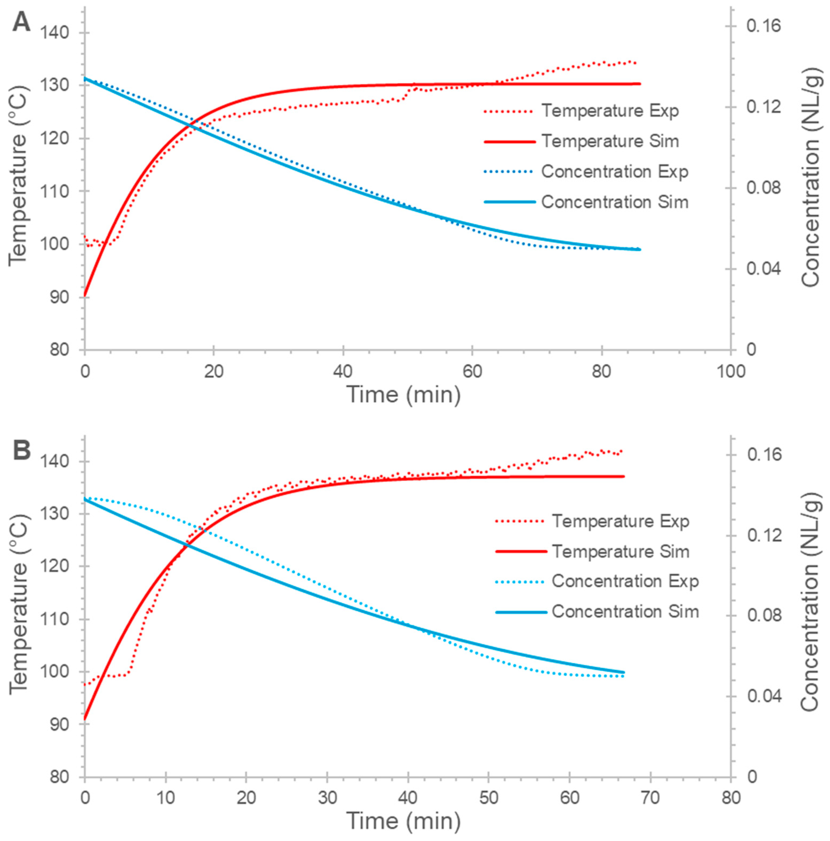
Figure 2 shows the performance of the model. This model was then used to generate training data by varying the operational input parameters and measuring the dynamic output. This data was then used to train an artificial neural network using the desired gas pressure, heating fluid temperature, and time as inputs and concentration as the variable the neural network would predict. These neural networks would vary in layer count and hidden neuron count using a ReLU activation and the Levenberg–Marquardt training algorithm. For this, both MathWorks MATLAB (R2025a) and TensorFlow (Version 2.19) were used with a 70–15–15 training–testing–validation split.
The trained models would then be re-validated against the experimental data, and performance would be analysed in terms of R-squared and mean-squared-error, which can be considered measures of the precision and accuracy of the model. Using simulated data to train the neural networks bypasses the need for extensive and expensive experimental trials.

3. Results and Discussion

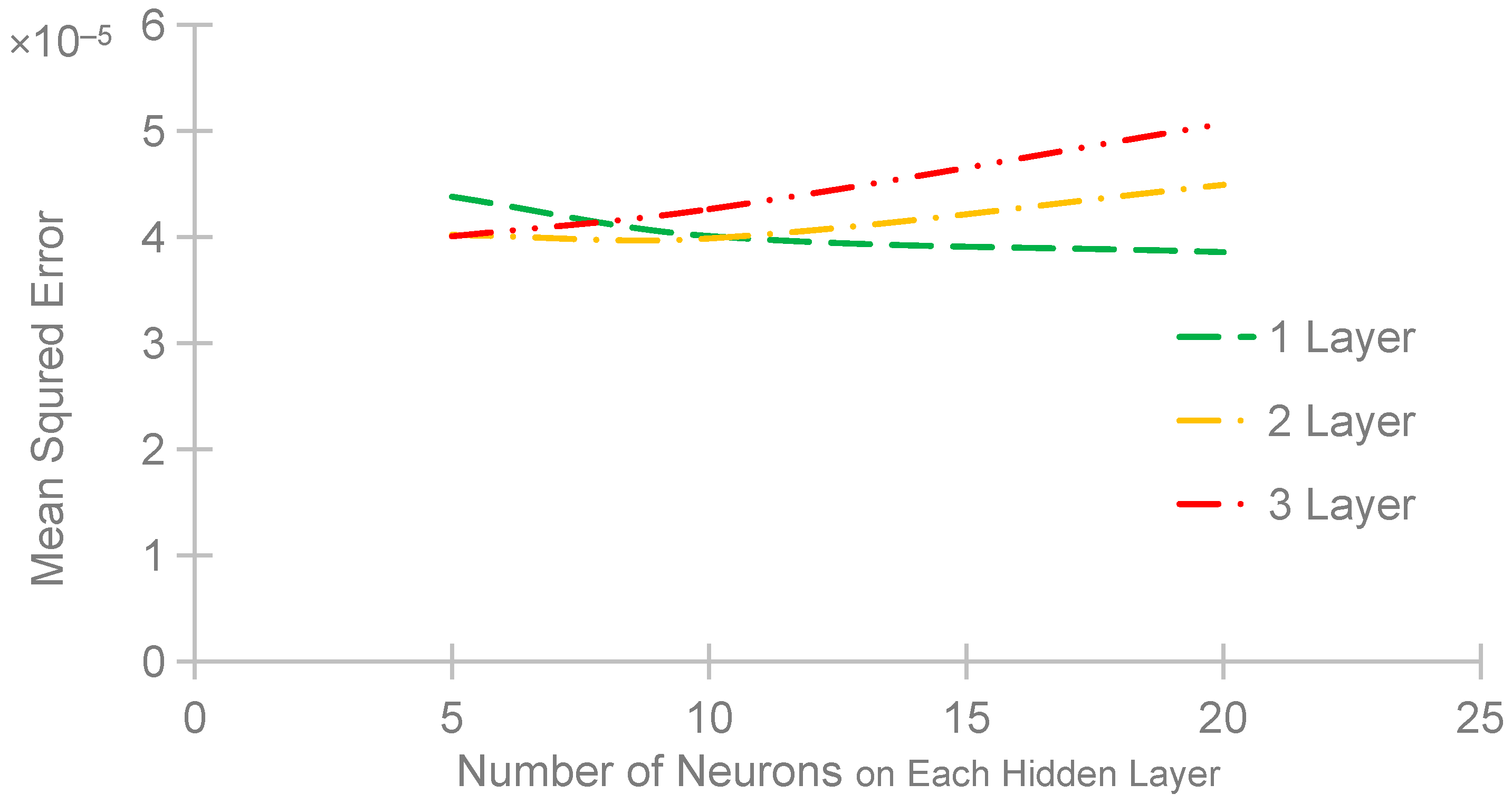
Figure 3 shows the final mean squared error of the nine different neural network architectures when evaluated on the experimental data regarding the discharge state. This is a fully connected neural network with one to three hidden layers and 5, 10, or 20 neurons on each hidden layer. While the mean squared error of all nine neural network architectures lies in the same range, the lowest observed mean squared error architecture with the least level of complexity is the two-layer architecture, with ten hidden neurons on each hidden layer. It should, however, be noted that the single-layer architecture is a contender as well, only being beaten by the two-layer architecture at five neurons, then outperforming the two-layer architecture at ten and twenty neurons on each hidden layer.
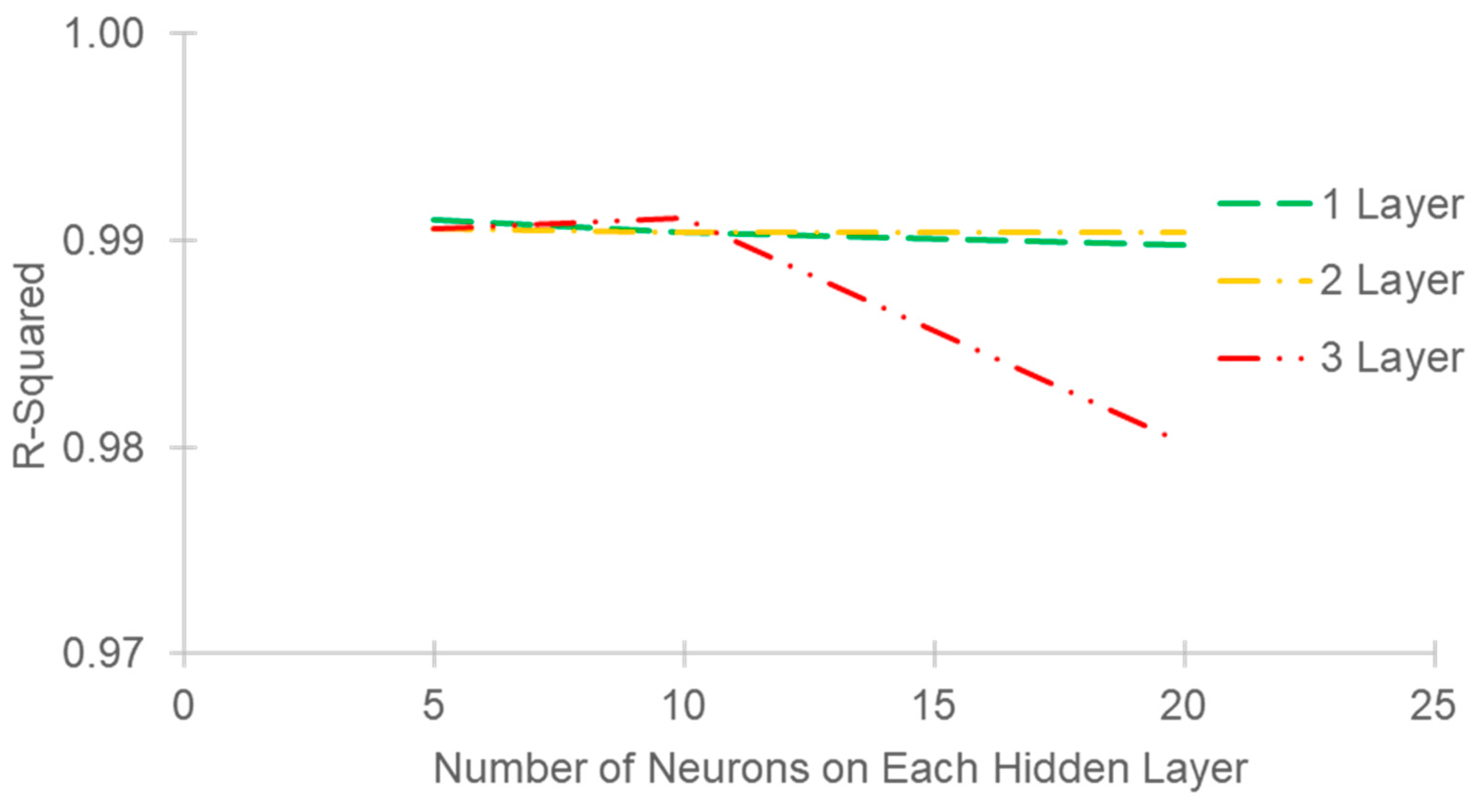
Figure 4 represents the R-squared performance of the nine neural network architectures when tested on the experimental data regarding the discharge state. This R-squared performance is observed during the linear regression of model-predicted values and the experimentally observed values. During this application, this may be referred to as the adjusted R-squared statistic as it does not measure the fit of the model on the dynamic data but only considers the predicted and observed data. This R-squared statistic measures how closely the model-predicted and experimentally observed data reflect each other; thus, a value closer to 1 is desired. It can be observed that the three-layer architecture with twenty neurons on each hidden layer has overfitted the data, performing much worse than the other architectures in this analysis. The other architectures performed equally well in this analysis.
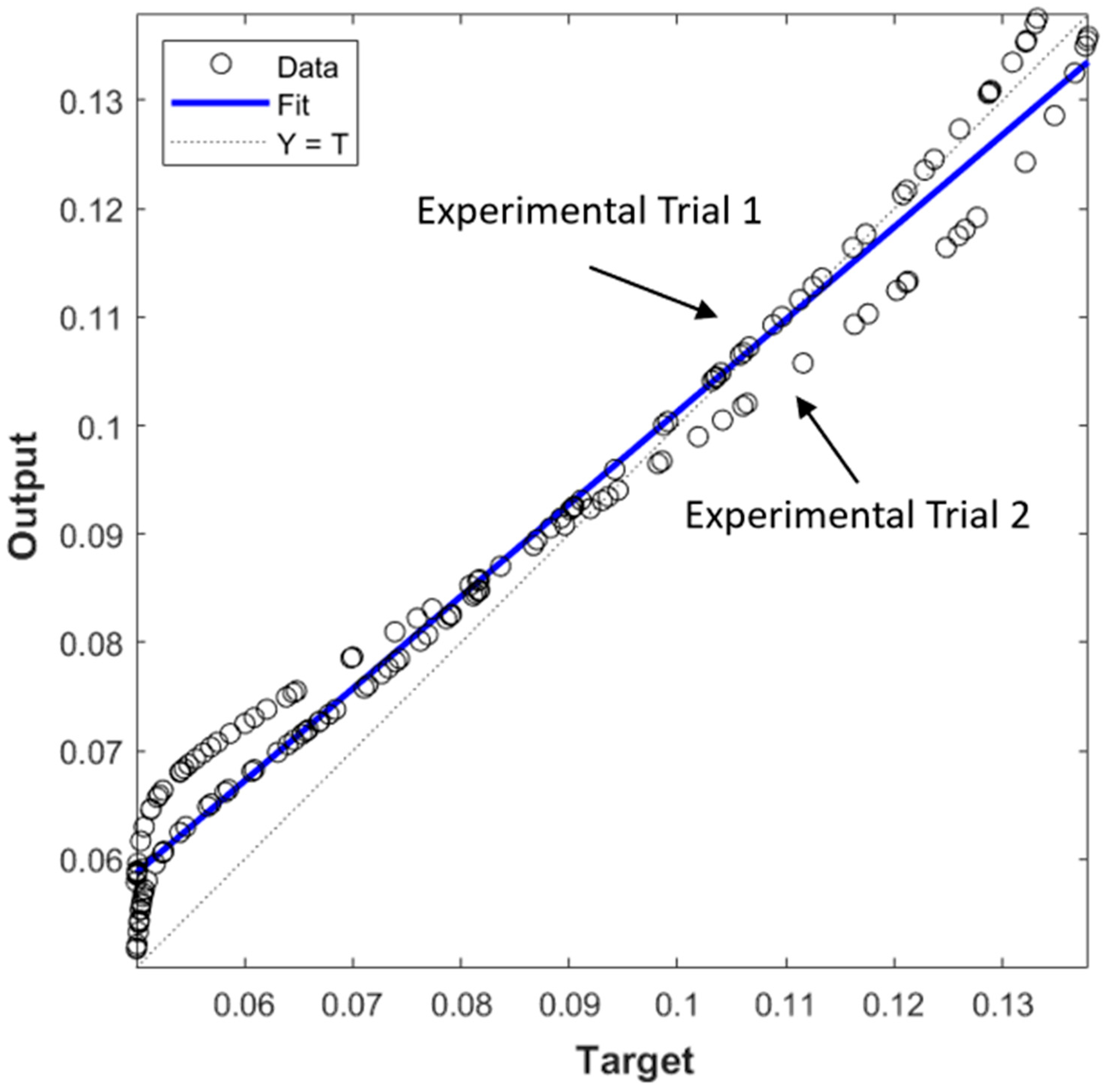
Figure 5 represents the linear regression of the model-predicted values against a sample of the experimentally observed data. Specifically, for the two hidden layers, ten neurons on each hidden-layer neural network architecture was determined to represent the best-performing neural network architecture for desorption. The R-squared in this instance was determined to be 0.99039. The two distinct curves that formed seem to denote the two different experimental trials, having differing degrees of accuracy for the whole of the dataset. Within the bounds of accuracy, this indicates that the model is not perfect.

4. Conclusions

The best-performing artificial neural network model achieved a regression coefficient of 0.9999 and a mean squared error of less than 10−5 during training. Likewise, the best-performing neural network model validation using the experimentally observed data achieved a regression coefficient of 0.99 and a mean squared error of less than 10−4. This proves that neural networks can model the complexity of metal hydride reactors during discharge, specifically the HySA-systems metal hydride reactor prototype.
This work serves as proof of concept that a predictive digital twin model can be generated for the discharge state of metal hydride reactors with further refinement. This refinement will come in the form of further computational fluid dynamics model validation, such as that of partial discharge capacity, and increasing the number of situation permutations that would be used to train the artificial neural network.

Supplementary Materials

The following supporting information can be downloaded at https://www.mdpi.com/article/10.3390/engproc2025117070/s1. Figure S1: High-resolution reactor schematic; Table S1: Figure S1, reactor schematic, part list according to numerical legend; Figure S2: COMSOL Multiphysics hydride bed geometry and mesh diagram; Table S2: PCT Isotherm fitting parameters; Table S3: Model parameters; Table S4: Length-wise contour plots for validation simulation in 10 min intervals; Table S5: Diameter-wise contour plots for validation simulation in 10 min intervals.

Author Contributions

Conceptualization, D.F.; methodology, D.F.; software, D.F. and M.M.; validation, D.F. and M.M.; formal analysis, D.F. and M.M.; investigation, D.F. and M.M.; data curation, D.F. and M.M.; writing—original draft preparation, D.F.; writing—review and editing, K.P.; visualisation, D.F.; supervision, K.P., A.K. and M.L. All authors have read and agreed to the published version of the manuscript.

Funding

This research received no external funding.

Institutional Review Board Statement

Not applicable.

Informed Consent Statement

Not applicable.

Data Availability Statement

The raw data supporting the conclusions of this article will be made available by the authors on request.

Acknowledgments

Douw Faurie acknowledges the Tshwane University of Technology for their personal financial support, as well as the University of the Western Cape and HySA systems for the experimental validation data.

Conflicts of Interest

The authors declare no conflicts of interest.

Nomenclature

t Time
ε p Porosity
ρ Density
u Velocity
Q m Flow rate
K Permeability
μ Viscosity
p Pressure
C p Heat capacity
q Heat flux
Q Heat transfer
Q v d Viscous dissipation heat losses
k e f f Effective thermal conductivity
m ˙ Hydrogen sorption rate in mass/volume/time
ρ s Dynamic hydride density
P g The pressure of the gas in the tank
T Temperature
C D Desorption rate constant
ρ 0 Standard hydride density
P e q The pressure of the gas in the hydride
R Ideal gas constant
E D Desorption activation energy

References

  1. Prachi, P.; Wagh, M.M.; Aneesh, G. A Review on Solid State Hydrogen Storage Material. Adv. Energy Power 2016, 4, 11–22. [Google Scholar] [CrossRef]
  2. Yartys, V.A.; Lototsky, M.V. An Overview of Hydrogen Storage Methods. In Hydrogen Materials Science and Chemistry of Metal Hydrides; Springer: Dordrecht, The Netherlands, 2004; pp. 75–104. [Google Scholar]
  3. Churchard, A.J.; Banach, E.; Borgschulte, A.; Caputo, R.; Chen, J.-C.; Clary, D.; Fijalkowski, K.J.; Geerlings, H.; Genova, R.V.; Grochala, W.; et al. A multifaceted approach to hydrogen storage. Phys. Chem. Chem. Phys. 2011, 13, 16955. [Google Scholar] [CrossRef] [PubMed]
  4. Adhy Lesmana, L.; Lu, C.; Chen, F.; Aziz, M. Topology optimization of gyroid structure-based metal hydride reactor for high-performance hydrogen storage. Therm. Sci. Eng. Prog. 2024, 50, 102533. [Google Scholar] [CrossRef]
  5. Krane, P.; Nash, A.L.; Ziviani, D.; Braun, J.E.; Marconnet, A.M.; Jain, N. Dynamic modeling and control of a two-reactor metal hydride energy storage system. Appl. Energy 2022, 325, 119836. [Google Scholar] [CrossRef]
  6. Costamagna, M.; Barale, J.; Carbone, C.; Luetto, C.; Agostini, A.; Baricco, M.; Rizzi, P. Environmental and economic assessment of hydrogen compression with the metal hydride technology. Int. J. Hydrogen Energy 2022, 47, 10122–10136. [Google Scholar] [CrossRef]
  7. Baldissin, D.; Lombardo, D. Thermofluidynamic Modelling of Hydrogen Absorption and Desorption in a LaNi4.8Al0.2 Hydride Bed. In Proceedings of the COMSOL Conference, Milan, Italy, 14–16 October 2009; pp. 1–7. [Google Scholar]
  8. Chibani, A.; Boucetta, C.; Merouani, S.; Tounsi, A.; Adjel, S.; Lamiri, L.; Bouchoul, B.; Merabti, H. Impact of fins and cooling fluid on the hydrogenation process in a LaNi5-Based metal hydride reactor for hydrogen storage. Int. J. Hydrogen Energy 2024, 69, 134–146. [Google Scholar] [CrossRef]
  9. Peng, C.; Liu, X.; Long, R.; Liu, Z.; Liu, W. Performance optimization of adsorption hydrogen storage system via computation fluid dynamics and machine learning. Chem. Eng. Res. Des. 2024, 207, 100–109. [Google Scholar] [CrossRef]
  10. Lototskyy, M.V.; Tolj, I.; Pickering, L.; Sita, C.; Barbir, F.; Yartys, V. The use of metal hydrides in fuel cell applications. Prog. Nat. Sci. Mater. Int. 2017, 27, 3–20. [Google Scholar] [CrossRef]
  11. Dong, Z.; Wang, Y.; Wu, H.; Zhang, X.; Sun, Y.; Li, Y.; Chang, J.; He, Z.; Hong, J. A design methodology of large-scale metal hydride reactor based on schematization for hydrogen storage. J. Energy Storage 2022, 49, 104047. [Google Scholar] [CrossRef]
  12. Aadhithiyan, A.K.; Anbarasu, S. Computational fluid modeling of lanthanum-based hydrogen storage reactors for heat pump applications. Int. J. Heat Fluid Flow 2024, 108, 109439. [Google Scholar] [CrossRef]
  13. Cui, Y.; Zeng, X.; Xiao, J.; Kou, H. The comprehensive review for development of heat exchanger configuration design in metal hydride bed. Int. J. Hydrogen Energy 2022, 47, 2461–2490. [Google Scholar] [CrossRef]
  14. Liu, Y.; Wang, H.; Prasad, A.K.; Advani, S.G. Role of heat pipes in improving the hydrogen charging rate in a metal hydride storage tank. Int. J. Hydrogen Energy 2014, 39, 10552–10563. [Google Scholar] [CrossRef]
  15. Verma, S.; Kishore, R.A.; Kumar, K.; Mitra, P.R. Dynamic modelling and control strategy of a temperature-driven metal hydride cooling system for buildings. Energy Build. 2025, 331, 115381. [Google Scholar] [CrossRef]
  16. Lototskyy, M.; Klochko, Y.; Wafeeq Davids, M.; Pickering, L.; Swanepoel, D.; Louw, G.; van der Westhuizen, B.; Chidziva, S.; Sita, C.; Bladergroen, B.; et al. Industrial-scale metal hydride hydrogen compressors developed at the South African Institute for Advanced Materials Chemistry. Mater. Today Proc. 2018, 5, 10514–10523. [Google Scholar] [CrossRef]
  17. Wang, D.; Wang, Y.; Huang, Z.; Yang, F.; Wu, Z.; Zheng, L.; Wu, L.; Zhang, Z. Design optimization and sensitivity analysis of the radiation mini-channel metal hydride reactor. Energy 2019, 173, 443–456. [Google Scholar] [CrossRef]
  18. Mellouli, S.; Askri, F.; Dhaou, H.; Jemni, A.; Ben Nasrallah, S. Numerical study of heat exchanger effects on charge/discharge times of metal–hydrogen storage vessel. Int. J. Hydrogen Energy 2009, 34, 3005–3017. [Google Scholar] [CrossRef]
  19. Xiao, J.; Tong, L.; Yang, T.; Bénard, P.; Chahine, R. Lumped parameter simulation of hydrogen storage and purification systems using metal hydrides. Int. J. Hydrogen Energy 2017, 42, 3698–3707. [Google Scholar] [CrossRef]
  20. Dunikov, D.O.; Borzenko, V.I.; Blinov, D.V.; Kazakov, A.N.; Romanov, I.A.; Leontiev, A.I. Heat and mass transfer in a metal hydride reactor: Combining experiments and mathematical modelling. J. Phys. Conf. Ser. 2021, 2057, 012122. [Google Scholar] [CrossRef]
  21. Jithu, P.V.; Mohan, G. Performance simulation of metal hydride based helical spring actuators during hydrogen sorption. Int. J. Hydrogen Energy 2022, 47, 14942–14951. [Google Scholar] [CrossRef]
  22. Faurie, D.G.; Premlall, K. Simulating non-ideal AB5 metal hydride pressure–concentration–temperature isotherms in MATLAB. Multiscale Multidiscip. Model. Exp. Des. 2025, 8, 194. [Google Scholar] [CrossRef]
  23. Faurie, D. Metal Hydride Single Segment Filling Fraction MATLAB Script; Mendeley Data: Amsterdam, The Netherlands, 2025. [Google Scholar]
  24. Faurie, D.; Premlall, K.; Koech, L. High-Resolution Simulated Metal Hydride Pressure-Concentration-Temperature Isotherm Data with Software. Chem. Data Collect. 2025, 59, 101202. [Google Scholar] [CrossRef]
  25. Faurie, D.; Premlall, K.; Kolesnikov, A.; Lototskyy, M. Sensitivity Analysis of a Metal Hydride Reactor Utilizing LaNi4.9Sn0.1 Metal Hydride. In Proceedings of the International Conference on Industrial Engineering and Operations Management, Paris, France, 2–4 July 2025; IEOM Society International: Southfield, MI, USA, 2025. [Google Scholar]
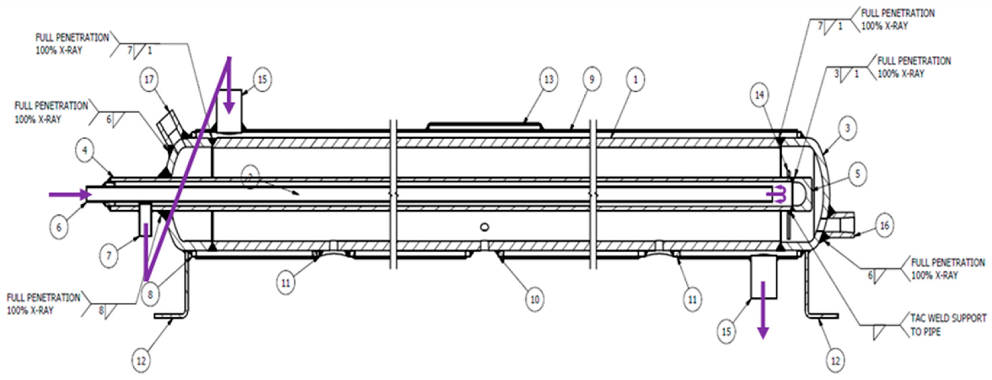
Figure 1. Schematic diagram of a hydride-based hydrogen compressor.
Engproc 117 00070 g001
Figure 2. Computational fluid dynamics validation with time versus concentration and temperature with (A) discharge gas pressure at 16.4 bar, with heating fluid at 135 °C, and (B) discharge gas pressure at 16 bar, with heating fluid at 142 °C.
Engproc 117 00070 g002
Figure 3. Mean-squared-error performance of the different neural network architectures when tested on the experimental data.
Engproc 117 00070 g003
Figure 4. R-squared performance of the different neural network architectures when tested on the experimental data.
Engproc 117 00070 g004
Figure 5. Regression of the two-layer, 10-neurons-on-each-hidden-layer network architecture model predictions against a randomised sample of experimental data.
Engproc 117 00070 g005
Disclaimer/Publisher’s Note: The statements, opinions and data contained in all publications are solely those of the individual author(s) and contributor(s) and not of MDPI and/or the editor(s). MDPI and/or the editor(s) disclaim responsibility for any injury to people or property resulting from any ideas, methods, instructions or products referred to in the content.