Abstract
Turbochargers operate under highly transient conditions, which impose significant mechanical and thermal loads on their rotating components. When supported by ball bearings combined with squeeze film dampers, the rotor system exhibits complex nonlinear dynamics that can critically affect bearing performance and service life. This study investigates the dynamic behaviour of ball-bearing-supported turbocharger rotors, focusing on lubrication conditions that reflect transient operating conditions. A high-fidelity computational model was developed to simulate multibody rotor dynamics, incorporating finite element-based flexible bodies and elastohydrodynamic lubrication (EHL) submodels to represent the contacts within the ball bearings. Validation of the simulation results against experimental data revealed that rotor vibrations significantly influence EHL contact, potentially leading to raceway damage. Additionally, differences in bearing loading between the inner and outer raceways, as well as between the compressor and turbine side bearings, were observed due to bearing clearance effects.
Keywords:
turbocharger; rotordynamics; ball bearings; transient loads; vibration; tribology; lubrication 1. Introduction
High-speed turbochargers play a critical role in modern powertrains and power generation systems, significantly improving their overall efficiency and performance. The increasing demand for faster transient responses while maintaining compact designs has led to ball bearing systems being adopted more widely for rotor support, replacing traditional oil hydrodynamic journal bearings in some specific applications. Although ball bearings offer advantages such as lower friction, higher rotational speeds and reduced oil consumption, they also present challenges relating to ball bearing tribology, rotor dynamics and system stability.
The tribological performance of the bearing system, including with the ball bearing assembly in the cartridge with a squeezed film damper (SFD), is highly sensitive to dynamic effects. Increased vibration levels lead to high contact stresses and fluctuating lubrication regimes, as well as the potential breakdown of lubrication film formation. These factors accelerate wear and can generate surface fatigue, significantly reducing the operational life of the bearings.
There is typically a strong coupling between rotor dynamics and ball bearing tribology, which necessitates the development of advanced computational models to simulate the transient behaviour of the rotor dynamics system and predict the resulting mechanical bearing loads and lubrication conditions. The objective of this study is to address this need by developing a computational model of a turbocharger rotor mounted in ball bearings and operating under highly transient conditions.
2. State of the Art
Many studies have focused on the nonlinear dynamics of rotor bearing systems, and key factors affecting the system behaviour such as bearing clearances, contact stiffness and nonlinearities, and elastohydrodynamic lubrication (EHL) have been identified. For example, the work of Nan et al. [1] simplistically analyzed the nonlinear response of a rotor system with ball bearings with wavy raceways, highlighting the significant nonlinearities of the system leading to chaos in some cases.
Other studies, such as that of Lu et al. [2], have investigated the nonlinear response of a rotor system supported by ball bearings, identifying complex nonlinear phenomena such as bifurcations and hysteresis that result from nonlinearities in the bearings.
Many papers have analyzed the issue of defects on bearing components, with an effect on the generation of subsynchronous and/or supersynchronous vibration components, an example being the work of Li et al. [3].
Despite these advances, most existing models remain limited in several respects. First, many models simplify bearings as linear springs and dampers, which does not reflect the true nonlinear behaviour of the contacts between the balls and the raceways. Second, the interactions between the balls and the bearing cage are often neglected, even though they have a significant effect on the dynamics of the system. For example, a study by Ma et al. [4] emphasized the importance of modelling the contacts between the balls and the cage for accurate vibration predictions.
Furthermore, many models do not take into account EHL, which is crucial for proper bearing operation at high speeds. The work of Liu et al. [5] showed that neglecting EHL effects can lead to underestimation of contact forces and consequently inaccurate prediction of bearing life.
The tribological performance of the bearing system, including the ball bearing assembly in the cartridge with the SFD, is highly sensitive to dynamic effects. The current state of knowledge reveals significant shortcomings, particularly in the formulation of general rotor dynamics models that incorporate EHL contacts. Describing the effects of rotor dynamics on bearing loads requires advanced multibody modelling with much more detailed models of individual interactions. Multibody dynamics are relatively well researched and some of the methods will be used in this case as well. Examples of such approaches can be found in Novotný et al. [6,7,8].
3. Solution Methods
A computational model of the rotor system is proposed to solve the structural dynamics of 3D-formulated rigid and flexible components through EHL interactions in the lubricating layer. The rotor bearing system computational model is built on the principle of commercial multibody dynamics software ADAMS 2024.2. Key interactions between bodies such as EHL or SFD bearings are added using custom functions to the multibody solver. This approach allows for efficient work when there is no need to programme routine functionalities such as calculating kinematic quantities. This allows for the use of general capabilities such as a general force element or 3D contact force to create interaction models for EHL or SFD.
3.1. Computational Models of the Rotor System Bodies
Solving structural dynamics problems is certainly a complex task and the chosen approach has to incorporate a certain degree of simplification. The rotor shaft is modelled as a three-dimensional elastic body, obtained via Craig–Bampton reduction from a finite element model. Large rigid motions are described using a floating reference frame and small elastic deformations using modal coordinates. Nonlinear effects, such as stress stiffening or spin softening, can be incorporated into the reduced elastic body by using an additional modal coordinate for the selected operating condition. These effects then remain unchanged over time during the simulation, regardless of speed. In this case, the rotor shaft is relatively short and stiff compared to the long rotors typically used. The Craig–Bampton analysis was performed around the non-prestressed configuration. For the investigated speed range (up to 50,000 rpm), the estimated influence of centrifugal stress stiffening and spin softening on the bending natural frequencies is below 1%, which is negligible compared to the effect of bearing stiffness variability. Therefore, these effects were not explicitly modelled.
Bodies for which deformation is insignificant are modelled as rigid 3D bodies with an analytical description of their surfaces. Examples include the central housing, which is formulated as a cylinder with closed bases that enable axial contact with the cartridge; the balls, which are formulated as spheres; and the cage, which is formulated as a set of radially oriented cylinders. The geometry of compressor or turbine wheels is not used for contacts and is imported as faceted geometry. For bodies for which local deformation is significant and which are modelled as rigid 3D bodies, an analytical description of local deformation is provided; for example, a ball or cartridge. The individual bodies of the rotor bearing system, including interactions, are schematically shown in Figure 1.
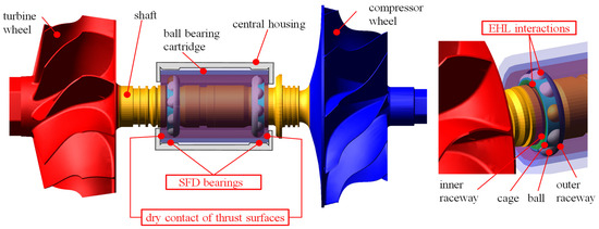
Figure 1.
Geometric representation of bodies in a rotor dynamics system model including interactions (highlighted in red) by angular contact ball bearings, SFD bearings and 3D contacts.
Since the geometry of the bodies is formulated in a very general way, the definition of clearances for the subsequent description of EHL ball bearings depends only on the position of the individual geometry of the bodies. It is thus relatively easy to set the axial clearance of a pair of angular contact bearings.
3.2. Computational Model of the EHL Interactions
The stiffness of the EHL contacts is provided by both the lubricant and the local stiffness of the contact surfaces. The damping is mainly caused by viscous friction in the lubricant. Material damping due to hysteresis in the contact bodies is generally very low. Determination of stiffness and damping in EHL contacts requires the solution of equations of motion for both the lubricant and the contacting structural elements. This solution can only be obtained numerically.
The stiffness in EHL contact can be determined from the constitutive equation, which relates the stiffness force to the mutual approach of the bodies. The approximation relations for the EHL stiffness and damping of two elliptical bodies under EHL proposed by Wijnant [9] was used. To estimate the minimum and central thicknesses of the lubrication layer, the relationships derived by Hamrock and Dowson [10], which are valid for any contact and now commonly used in EHL film thickness calculations, were used. The numerically derived relationship for the minimum film thickness is
where is the entrainment speed, which is calculated from the surface velocities of the two bodies in contact, is the viscosity at atmospheric pressure of the lubricant under operation temperature, is the pressure–viscosity coefficient, is the contact load, is the ellipticity parameter, is the reduced elasticity modulus and is the reduced radius of curvature. The given approximation relations (1) do not take into account zero force, but during dynamic calculation, zero force can occur, so these relations are numerically limited only for forces greater than 0.001 N.
When studying EHL friction, it is important to note that, except at very low sliding speeds, a significant amount of heat is dissipated in the EHL contact, raising the temperature of the oil film above its entry temperature. This generally has a negligible effect on the EHL film thickness, which depends on the properties of the lubricant entering the contact, but for most lubricants, it leads to a reduction in EHL friction at high sliding speeds. The temperature rise in the contact can be estimated as follows [11]
where and are the thermal conductivities of the surface material, respectively, and the oil, is density of the material, is specific heat capacity of the material, is the mean film pressure in contact area, is the friction coefficient and is the sliding speed.
The given EHL model is implemented in multibody software. In the case of contact between two rigid bodies with 3D analytical geometry, the contact surfaces of the bodies are analytically evaluated and the penetration is calculated as the largest value of the contact surface local penetrations.
3.3. Computational Model of the SFD
The SFD incorporates a pair of hydrodynamic oil bearings that provide interaction between the bearing cartridge and the central housing. The bearing cartridge, which carries the pair of ball bearings, is free to move in radial direction but is prevented from rotating. Together with the SFD, it represents an efficient damping element without major mechanical losses. SFD oil film lubrication, including heat transfer, is generally described by the equations of conservation of mass, momentum, and energy. Using the simplified assumptions defined by Novotny et al. [12], lubricant flow can be described by the Reynolds equation for hydrodynamic lubrication. This approach also considers heat transfer due to internal shear stresses and to surrounding structures. Thus, a given hydrodynamic problem can be solved separately from the rotor system, and the bearing load-carrying capacity, friction torques, and lubricant mass flow rates can subsequently be approximated from hydrodynamic databases [12].
3.4. Computational Model of Dry Contacts
Contacts where EHL has a negligible effect on rotor dynamics and, at the same time, there is no requirement for detailed description are formulated as 3D solid dry contacts. These contacts include the contact of the cartridge and the stator part of the central housing axially carrying the axial force and the contact of the ball and cage. The contact stiffness is formulated according to Hertzian theory of contacts between two bodies with a parabolic contact surface. A description of the 3D contacts used can be found in [13].
4. Results and Discussion
The developed computational model of rotor bearing system allows for obtaining a very large number of different types of results. Their consistent presentation would require a considerable scope, and therefore only some quantities are presented, especially those that are can be directly verified by experiments and those that characterize the tribological quantities of selected EHL contacts between the ball and the outer or inner raceways. These tribological quantities demonstrate specific properties of EHL contacts in high-speed rotors under strong transient operation conditions.
4.1. Turbocharger Operating Conditions
The turbocharger is typically measured in a transient operation, where the speed gradually increases from minimum to maximum. During this start-up, individual quantities are evaluated. The duration of the turbocharger start-up is typically in the order of a few minutes. However, for the purposes of rotor dynamics simulation, such long start-up times are unnecessarily long and computationally demanding, and therefore the duration of the turbocharger start-up is reduced to the order of a few seconds for the simulation. Although this is a significantly shorter duration, there is no longer a disproportionate influence of transient system behaviour, and the simulation results can be compared with the experiment. In the case of this study, the rotor was started up from a rotor speed of to for 4 s.
The rotor is loaded in the radial direction by the unbalance on the impellers. In the axial direction, the rotor is loaded by the resulting axial force due to the pressure ratios on the impellers and the impulse forces due to the momentum of the fluid. The axial load was determined based on the measured pressures, temperatures and flows in the compressor and turbine using the methodology according to [14]. An overview of the values used to generate the rotor load is presented in Table 1. The axial forces in Table 1 are continuously increasing rotor speed and interpolated by a cubic spline.

Table 1.
Parameters defining the turbocharger rotor load.
The measured turbocharger was operated on a test bench with SAE 10W-40 engine oil at an inlet oil temperature of 30 °C and an inlet gauge pressure of 2 bar (g).
4.2. Verification of Rotor Dynamics Using a Technical Experiment
Verification was carried out on a turbocharger on a test bench. Verification of the computational model of the rotor bearing system was carried out by measuring the movement of the compressor nose during smooth rotor start-up. Figure 2 compares the calculated and measured deflections on the compressor nose in the axis perpendicular to the ground. For comparison purposes, the deflection values were normalized.
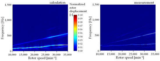
Figure 2.
Calculated and measured displacement of the compressor wheel nose in the axis perpendicular to the ground.
The results of the calculation and experiment in Figure 2 show mainly the synchronous frequency of vibration in the frequency spectrum due to rotor misalignment, which corresponds to the rotor speed frequency. The subsynchronous component of the vibration at a frequency of approximately 200 Hz is also clearly visible in the vibration spectrum, which is due to the existence of backlash in the ball bearing and system nonlinearity. There is also a less obvious supersynchronous component in the frequency spectrum due to frequency modulation of the two previous excitation frequency components. The modulating frequency component is the subsynchronous component and the carrier frequency is the synchronous component from the unbalance.
4.3. Evaluation of Ball Bearing EHL Contacts
One of the typical parameters that indicates the load on the ball–raceway contacts is the value of the Hertzian pressures. Hertzian pressures are important for assessing bearing life and the risk of surface damage. The maximum Hertzian pressures in ball bearings at EHL depend on several factors such as load, contact geometry, material properties and operating conditions. The maximum Hertzian pressure values calculated in the simulation are presented in Figure 3. For ball bearings in high-speed applications, such as turbochargers, maximum Hertzian pressures are typically in the range of 1.5 to 3.5 GPa. Hertz pressures above 4 GPa are usually considered risk-averse because they can lead to fatigue damage (pitting) or plastic deformation of the material, especially in steel bearings. Bearing manufacturers recommend designing bearings to keep maximum Hertzian pressures below 3 GPa to ensure long life. It is clear that the analyzed bearings are at the limit of acceptable load, especially in the area of medium and high speeds.
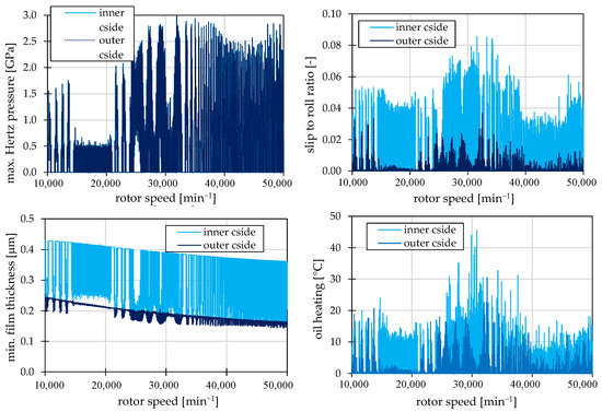
Figure 3.
The results obtained by simulation include maximum Hertzian pressures (top left), slip to roll ratios (top right), central film thicknesses (bottom left), and oil heating in the contact zone (bottom right). Only the results of the ball raceway contact of the ball bearing on the compressor side are presented.
The ratio of slip speed to rolling speed of ball relative to raceway, referred to as the slip-to-roll ratio (SRR), is a key parameter in the analysis of ball bearing dynamics, especially in EHL. A higher SRR means a higher slip rate, which increases friction and heat generation in contact. This can lead to overheating of the bearing and a reduction in lubricant viscosity, which negatively affects the lubrication film thickness. SRR can also be used to estimate energy loss and thermal stress on the bearing. Under optimum conditions with good EHL and low preload, slip is minimal and the motion is almost rolling. SRR values are typically in the range of 0.01 to 0.1. The calculated values for the bearing on the compressor side are presented in Figure 3. When comparing the SRR values on the outer and inner raceways, a significant difference is evident. The outer raceway is more pre-loaded due to centrifugal force, the SRR values are lower and therefore the rolling motion is more dominant.
A key parameter in the evaluation of EHL ball bearings is the minimum thickness of the lubrication layer between the ball and the raceways. The thickness of the lubrication layer in EHL depends on several factors such as rolling speed, load, lubricant properties, bearing geometry and material properties. In EHL ball bearings, the thickness of the lubrication layer is typically in the range of 0.1 to 2 for common high-speed applications. The calculated values for the compressor side bearing are presented in Figure 3. Again, the difference between the outer and inner raceway is clearly visible, with the thickness on the outer raceway showing significantly less oscillation due to centrifugal force. At the same time, however, it can be seen that smaller values are achieved on the inner path and thus the probability of fatigue damage is higher here.
5. Conclusions
This study presents an advanced 3D computational model for the rotor dynamics analysis of a high-speed turbocharger supported by ball bearings. The study focuses on transient operating conditions and detailed EHL interactions. The proposed model is a fully 3D formulated rotor-bearing system that incorporates nonlinear 3D contact mechanics, bearing clearances and realistic interactions between the balls, raceways and cage.
The results highlight two key findings that cannot be sufficiently addressed in simplified bearing models:
- Asymmetry in EHL raceway contacts: Significant differences in contact loading and EHL film characteristics were observed between the outer and inner raceways. This asymmetry is primarily driven by centrifugal forces acting on the rolling elements, which alter the contact loads and lubrication behaviour. This can result in uneven wear on the outer and inner raceways, affecting the bearing’s overall durability, particularly at high rotational speeds.
- Side-specific bearing behaviour: The comparison between the compressor-side and turbine-side bearings revealed considerable differences in load and dynamic behaviour. In particular, the presence of bearing clearances in the compressor-side bearing, combined with axial thrust loading under compressor-pulling operation, results in a nonlinear response, greater displacement amplitudes, and increased sensitivity to transient excitations. This leads to nonuniform bearing support stiffness across the rotor and must be carefully considered in both design and diagnostics.
The main advantage of the developed model lies in its high fidelity and realistic representation of 3D contact interactions, enabling the accurate prediction of bearing forces, lubrication regimes, and dynamic responses under a wide range of conditions. Unlike traditional lumped-parameter or 2D models, this approach captures subtle physical effects that are crucial for high-speed, high-load applications such as turbochargers.
However, the model comes with certain limitations. The computational cost is significantly higher due to the increased number of degrees of freedom and slightly due to the use of the EHL submodels. A certain disadvantage is the need to provide a large number of model input parameters (typically dozens to hundreds), which are often difficult to obtain either from typically available input data or from experiments. However, this disadvantage is generally valid for all advanced models. Additionally, the sensitivity of the results to detailed input parameters such as lubricant properties, clearances under operating conditions, and thermal loading of turbocharger components reduce robustness in industrial use cases where such data are often uncertain or unavailable.
Despite these limitations, the computational model developed offers a powerful tool for investigating the critical phenomena that influence bearing performance and turbocharger reliability. Future work will focus on the multiphysical nature of modelling while improving computational efficiency.
Author Contributions
Conceptualization, P.N.; methodology, P.N.; validation, J.V., F.K. and A.K.; formal analysis, J.V.; investigation, P.N.; resources, F.K.; data curation, A.K.; writing—original draft preparation, P.N.; writing—review and editing, J.V.; visualization, P.N.; supervision, P.N.; project administration, P.N. All authors have read and agreed to the published version of the manuscript.
Funding
This publication was supported by the project “Innovative Technologies for Smart Low Emission Mobilities”, funded as project No. CZ.02.01.01/00/23_020/0008528 by Programme Johannes Amos Comenius, call Intersectoral cooperation.
Institutional Review Board Statement
Not applicable.
Informed Consent Statement
Not applicable.
Data Availability Statement
The data used in this study are not publicly available, but can be obtained from the author upon request.
Conflicts of Interest
The authors declare no conflicts of interest.
References
- Nan, G.; Zhang, Y.; Zhu, Y.; Guo, W. Nonlinear dynamics of rotor system supported by bearing with waviness. Sci. Prog. 2020, 103, 0036850420944092. [Google Scholar] [CrossRef] [PubMed]
- Lu, Z.; Zhong, S.; Chen, H.; Wang, X.; Han, J.; Wang, C. Nonlinear response analysis for a dual-rotor system supported by ball bearing. Int. J. Non-Linear Mech. 2021, 128, 103627. [Google Scholar] [CrossRef]
- Li, Y.; Li, Z.; He, D.; Tian, D. Nonlinear dynamic characteristics of rolling bearings with multiple defects. J. Vib. Eng. Technol. 2023, 11, 4303–4321. [Google Scholar] [CrossRef]
- Ma, S.; Yan, K.; Liu, Y.; Liang, P.; Yin, Y.; Fang, B.; Hong, J. An investigation on cage instability based on dynamic model considering guiding surface three-dimensional contact. Nonlinear Dyn. 2024, 112, 289–315. [Google Scholar] [CrossRef]
- Liu, J.; Tang, C.; Pan, G. Dynamic modeling and simulation of a flexible-rotor ball bearing system. J. Vib. Control 2022, 28, 3495–3509. [Google Scholar] [CrossRef]
- Novotný, P.; Kudláček, P.; Vacula, J. Explanation of the mechanisms of unsteady gas flow through the turbocharger seal system, including thermal and structural interactions. Propuls. Power Res. 2023, 12, 180–198. [Google Scholar] [CrossRef]
- Novotný, P.; Vacula, J.; Hrabovský, J. Solution strategy for increasing the efficiency of turbochargers by reducing energy losses in the lubrication system. Energy 2021, 236, 121402. [Google Scholar] [CrossRef]
- Novotný, P.; Hrabovský, J.; Juračka, J.; Klíma, J.; Hort, V. Effective thrust bearing model for simulations of transient rotor dynamics. Int. J. Mech. Sci. 2019, 157–158, 374–383. [Google Scholar] [CrossRef]
- Wijnant, Y.H. Contact Dynamics in the Field of Elastohydrodynamic Lubrication. Ph.D. Thesis, University of Twente, Enschede, The Netherlands, 1998. [Google Scholar]
- Hamrock, B.J.; Schmid, S.R.; Jacobson, B.O. Fundamentals of Fluid Film Lubrication; CRC Press: Boca Raton, FL, USA, 2004. [Google Scholar]
- Zhang, J.; Spikes, H. Measurement of EHD friction at very high contact pressures. Tribol. Lett. 2020, 68, 42. [Google Scholar] [CrossRef]
- Novotný, P.; Škara, P.; Hliník, J. The effective computational model of the hydrodynamics journal floating ring bearing for simulations of long transient regimes of turbocharger rotor dynamics. Int. J. Mech. Sci. 2018, 148, 611–619. [Google Scholar] [CrossRef]
- MSC Software. Adams Solver User Guide. Available online: https://nexus.hexagon.com/documentationcenter/en-US/bundle/Adams_2022.4_Adams_Solver_User_Guide/resource/Adams_2022.4_Adams_Solver_User_Guide.pdf (accessed on 28 May 2025).
- Nguyen-Schäfer, H. Rotordynamics of Automotive Turbochargers, 2nd ed.; Springer: Ludwigsburg, Germany, 2015. [Google Scholar]
Disclaimer/Publisher’s Note: The statements, opinions and data contained in all publications are solely those of the individual author(s) and contributor(s) and not of MDPI and/or the editor(s). MDPI and/or the editor(s) disclaim responsibility for any injury to people or property resulting from any ideas, methods, instructions or products referred to in the content. |
© 2025 by the authors. Licensee MDPI, Basel, Switzerland. This article is an open access article distributed under the terms and conditions of the Creative Commons Attribution (CC BY) license (https://creativecommons.org/licenses/by/4.0/).