Abstract
The technological process of the centrifugal casting of short and long castings is examined during development. The values of the technological parameters at applying heat-resistant coating on the working surface of metal molds were established. With a high-speed camera, the temperature of the free surface during the pouring of the melts was measured. Research experiments were conducted. A mathematical model of the centrifugal casting process with a horizontal axis was created.
1. Introduction
A modern trend in the development of centrifugal metal casting is the use of different grades of steel (ordinary, structural, low-alloyed), and subsequently medium- and high-alloyed steels [1,2,3,4,5,6,7,8].
Part of the technological parameters of this process is the angular velocity of the metal mold during molding and the mass velocity of pouring the melts. They determine the hydrodynamic phenomena associated with the nature of the process, namely the formation of a continuous circular melt flow limited by the inner surface of the metal mold and a continuous longitudinal melt flow determining the length of the casting and the wall thickness. Another part of the technological parameters is important in obtaining the heat-resistant coating on the metal mold [9,10,11,12,13,14].
The heat transfer of the metal melt from the formed free surface, the thermal conductivity of the outer solid layer through the heat-resistant coating and the wall of the metal mold, and the heat transfer from the outer surface of the mold to the adjacent air environment have a solid theoretical basis through the heat conduction equation and Newton’s law of heat transfer [15].
However, research in the field of centrifugal casting is very limited and usually concerns individual parameters of the overall process and the influence of temperature on other design and technological parameters.
2. Methodology and Methods
The main task in the current research concerns the determination of technological parameters in the centrifugal formation of melts and heat transfer processes in the dynamics of the process.
The theoretical results for determining the angular velocity are based on the solutions of the Navier–Stokes hydrodynamic equations and are made under a number of simplifying assumptions, both with respect to the initial and boundary conditions.
The issue of determining the mass flow rate of the melt into the metal mold through a short channel with a limited light opening is topical and important. The linear velocity of the axial and helical motion of the melt, as well as the rate of increase in the wall thickness of the casting, directly depends on the mass flow rate and the angular velocity of the mold.
Regarding the method of applying the lute and obtaining the heat-resistant coating on the working surface of the metal mold, it is necessary to determine the main technological parameters for this process: the diameter of the light opening of the nozzle through which the lute flows, the pressure of the medium in the agitator above the lute, the flow rate of the lute, the pressure and flow rate of the spraying air, the temperature of the metal mold, its angular velocity during lute application, the linear speed of the luting trolley, and the amount of lute per cycle. The constancy of these parameters during the process determines the uniformity and thickness of the resulting heat-resistant coating.
As a result of the above, the physics of the centrifugal metal casting process are based on hydrodynamics, heat transfer in a pulsating force field. The main forces constituting this field are centrifugal forces and gravity forces, which are applied to the elementary volume of the continuous medium being formed—the casting.
The mathematical apparatus in this case consists of the Navier–Stokes equations, the Fourier–Kirchhoff equation, and the equations of mechanics. The hydrodynamics of the forming process are reduced to tangential, axial, and centrifugal forces, as a result of which the metal mold is filled with melt. The non-stationary temperature field is described by the Stefan-Schwarz task.
3. Results
3.1. Scheme for Mathematical Modeling of Centrifugal Casting of Short Castings
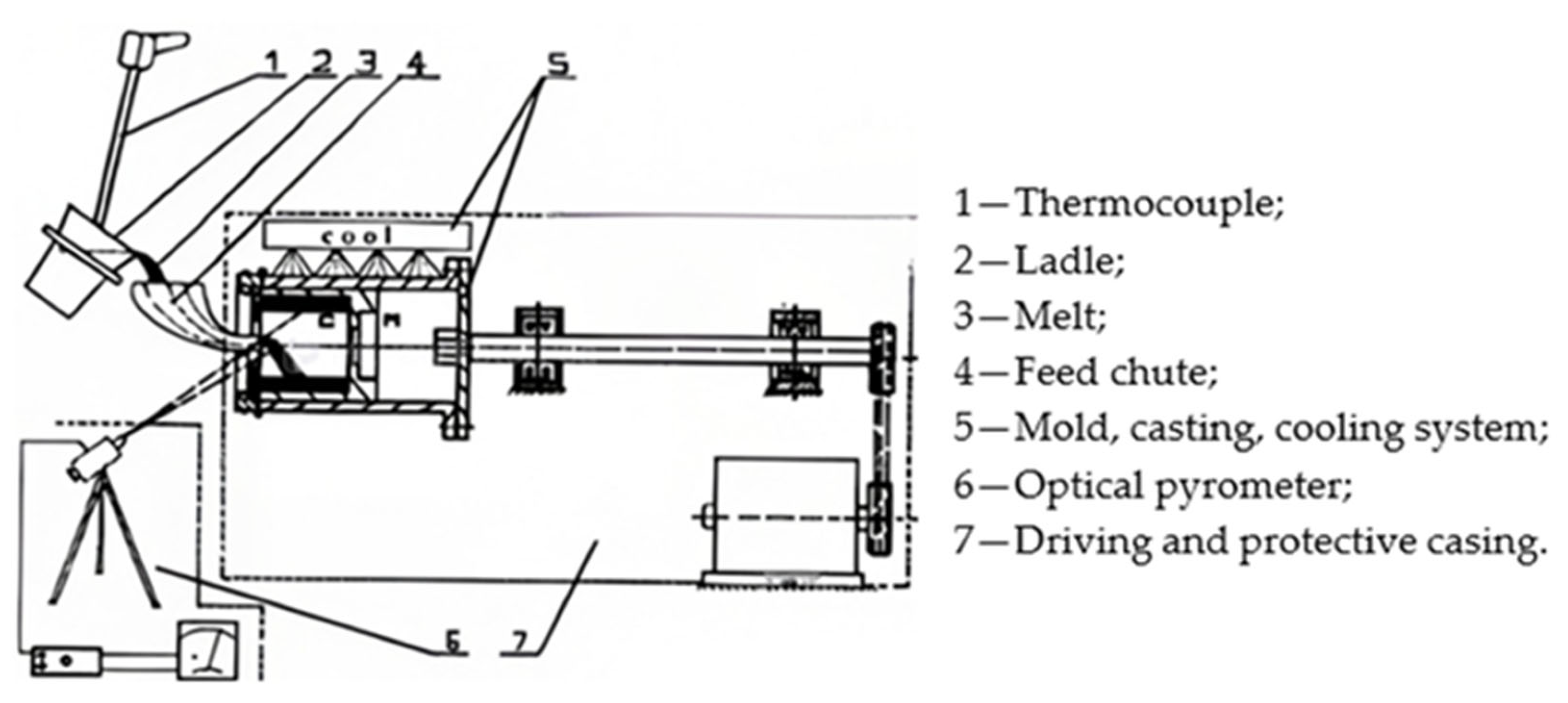
Figure 1 shows a basic diagram of a cantilever machine model 553–2.
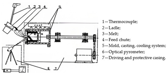
Figure 1.
Basic diagram of cantilever machine model 553–2.
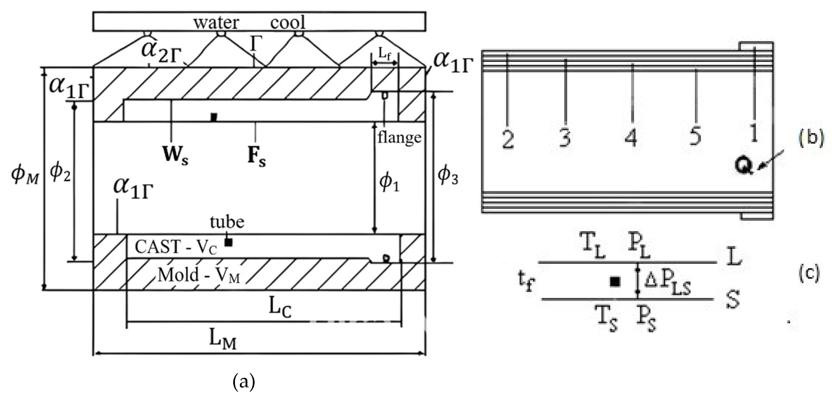
The designations of the general geometric scheme (Figure 2) are as follows:
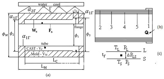
Figure 2.
General geometric scheme for mathematical modeling (a–c).
- (a)
- Geometric dimensions: L—lengths; φ—diameters; Γ, Ws—outer and working surface of the mold; Fs—free surface of the casting, where heat transfer is neglected, cooled with a water shower; α1Γ and α2Γ—mold–environment heat transfer coefficients;
 ,
,  —volumes for evaluating the conditions of the structure-formation at a flange and pipe.
 - (b)
- Dividing the cast into five volumes to assess the filling.
- (c)
- tf—local solidification time: residence time of a considered volume of the casting in the two-phase zone; TL, TS—isothermal liquidus and solidus surfaces; ΔPLS—difference between the pressures for two opposite points of TL and TS.
3.2. Scheme for Mathematical Modeling of Centrifugal Casting of Long Castings
The process of filling the mold with molten metal (Figure 3) was filmed with a high-speed camera from the beginning of pouring to complete filling with molten metal, tracking the heat exchange process between the formed casting, the heat-resistant coating, and the wall of the metal mold along its entire length. The solidification process is presented as follows:
- Cooling after the end of filling;
- Filming of air release at the hot end;
- Cooling after the end of filling.
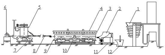
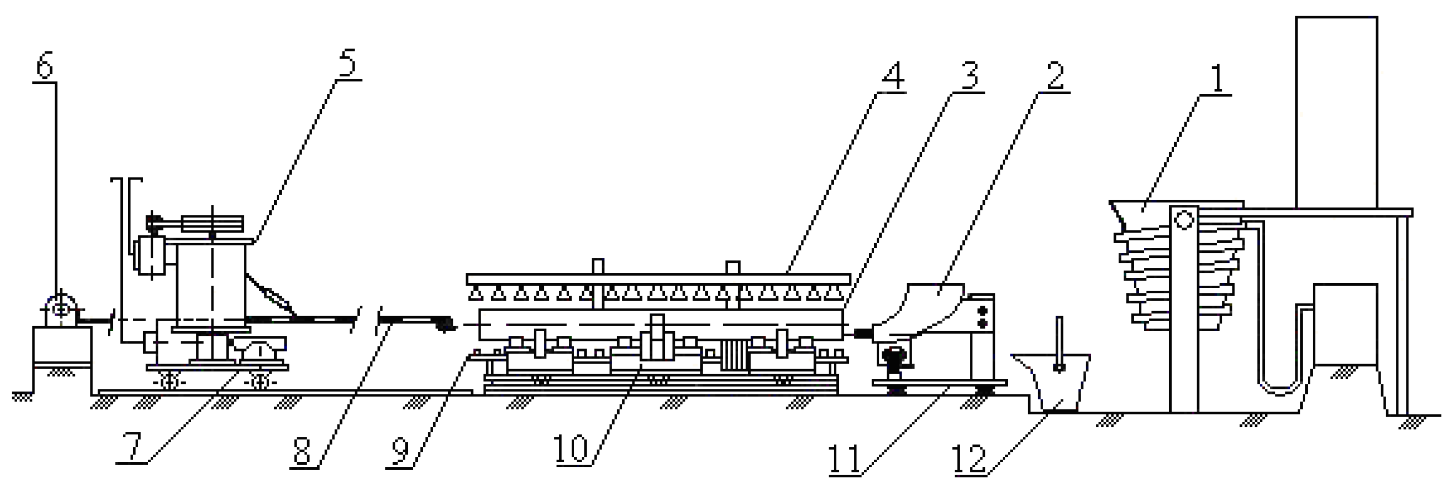
Figure 3.
Basic diagram of a machine for centrifugal casting of long pipes. 1—Induction furnace; 2—chute; 3—metal mold; 4—heater; 5—mixer; 6—winch; 7—mixer trolley; 8—coating manipulator; 9—cooler; 10—support bearing; 11—chute trolley; 12—ladle.
Figure 3.
Basic diagram of a machine for centrifugal casting of long pipes. 1—Induction furnace; 2—chute; 3—metal mold; 4—heater; 5—mixer; 6—winch; 7—mixer trolley; 8—coating manipulator; 9—cooler; 10—support bearing; 11—chute trolley; 12—ladle.
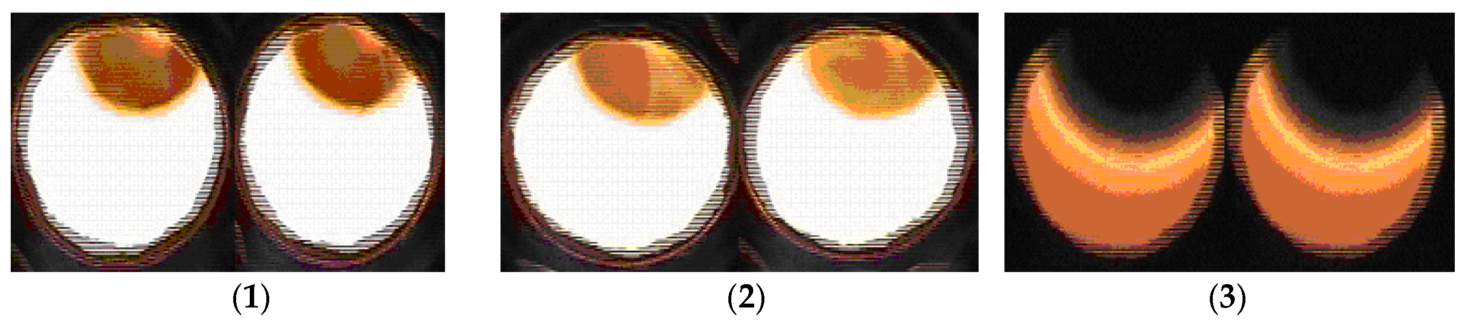
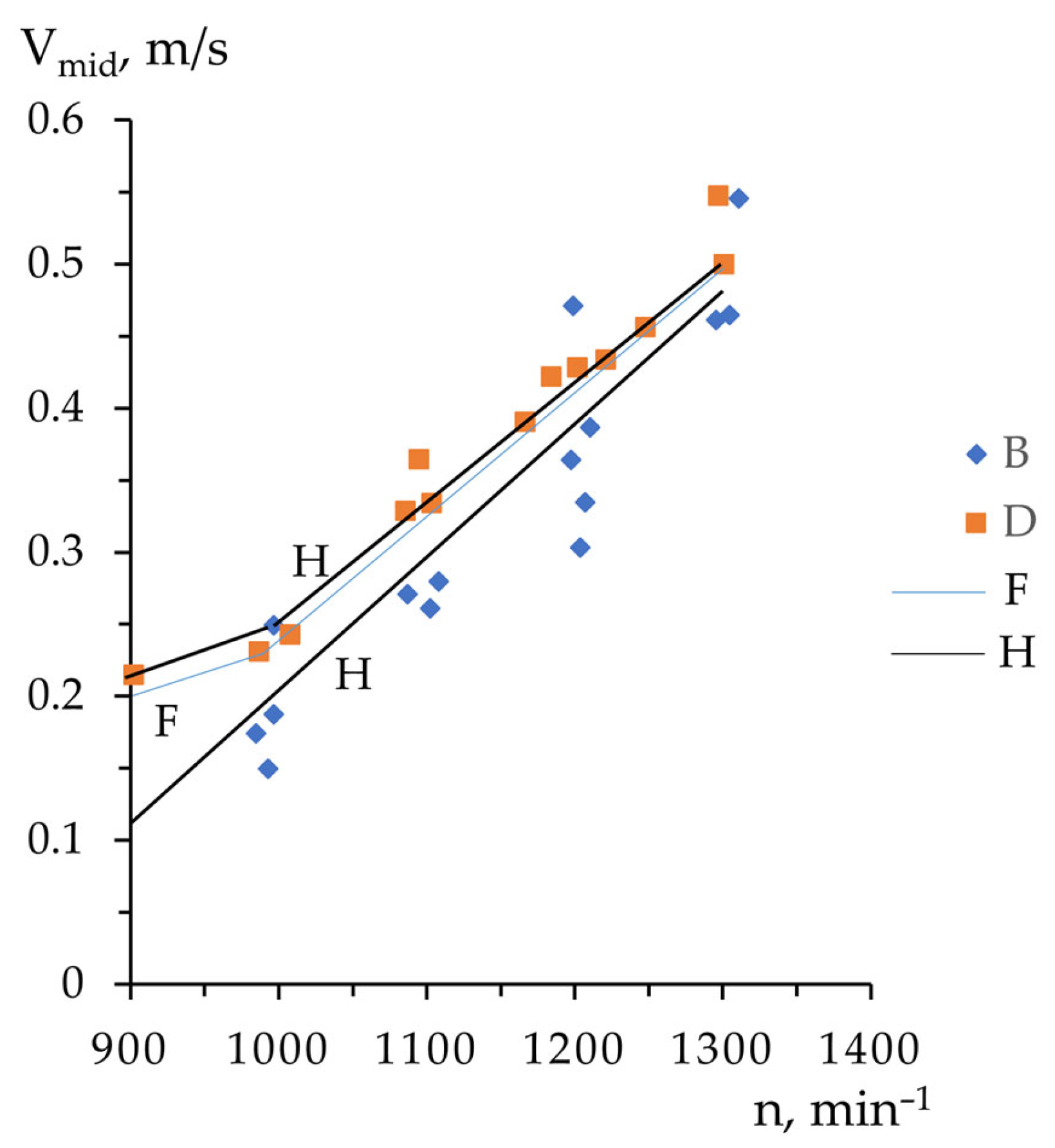
By directly observing the movement of the melt along the entire horizontal length (Figure 4), the axial velocity of the melt movement was determined, measured as a function of the mold rotation speed (Figure 5).
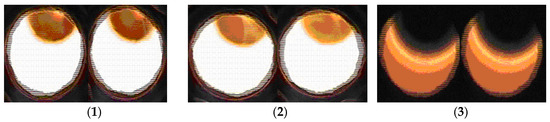
Figure 4.
Depiction of the geometry of the shape forming in the visible part of the first layer and last movie frame from the pouring of the metal.
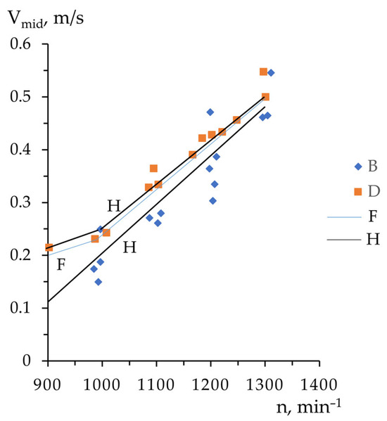
Figure 5.
Average melt movement speed as a function of rotation parameters in the technological interval from 900 up to 1300 min−1.
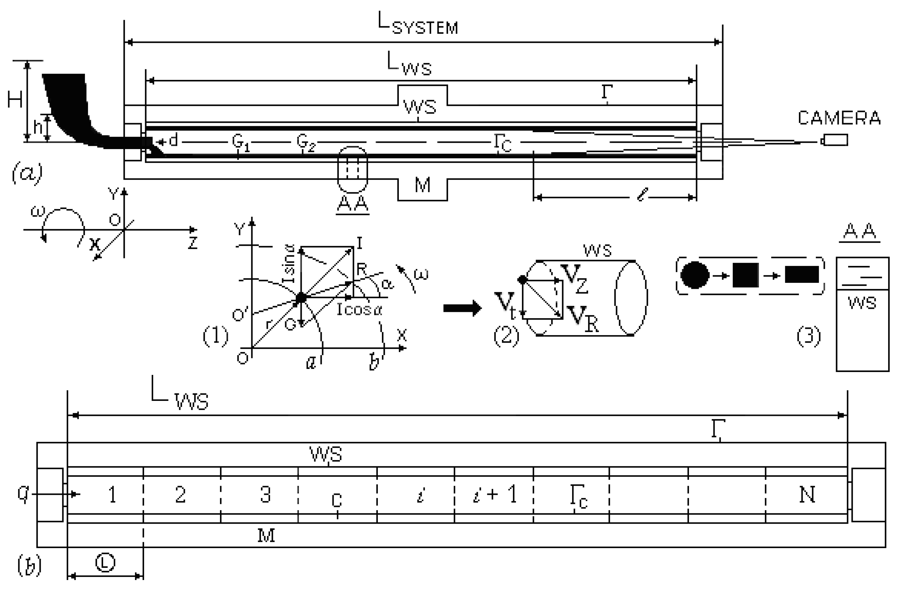
Figure 6 shows the basic technological scheme of the centrifugal casting process, where (C)—casting; (M)—mold; runner with boundary surfaces: casting/mold (WS), and external/free—Γ (ΓC):
- (a)
- Casting C—before filling (
 ) and casting C—after filling (
 ) with weights of layers, respectively, G1 and G2; H—pouring height; h—height of the melt in the runner with a clear open diameter (d); LSYSTEM—length of BTS; LWS—length of work surface;
  – (WS) invisible part of the camera; —imaginary section from OTC micromodel of Stefan-Schwartz task, according to [1]; OXYZ—coordinate system; ω—angular velocity of rotation; (1)—force field on a single particle of liquid metal in the cross section OXY; I—centrifugal force; G—weight force; R—resultant force; a—cylindrical surface shaped by equal pressure of the force field and the working surface (WS); OO/—eccentricity due to applied forces along the horizontal axis of rotation; b—oval surface described by the tip of the force vector R; (2)—velocity field of the molten metal particle; Vt—tangential, VZ—axis, and VR—resultant speed; (3) geometric model of liquid drop spillage with micromodel of Stefan-Schwartz task, according to [16,17].
 - (b)
- Geometric idea for the mathematical modeling of the process of forming the first layer of molten metal, where q—flow rate, M—shape, and C—casting, composed of N volume elements of equal length
 .
.
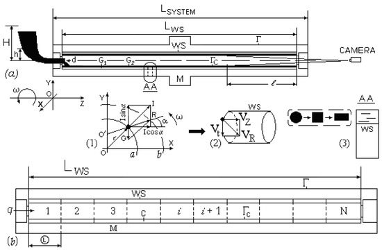
Figure 6.
Basic technological scheme (BTS) (a,b).
Figure 6.
Basic technological scheme (BTS) (a,b).
4. Discussion
The mathematical model of the centrifugal casting process is based on the following equations:
Inertial centrifugal force:
Gravity:
Resultant force:
Free surface equation:
Pressure distribution in the melt:
Navier–Stokes equations:
Continuity equation:
Initial conditions:
Established melt and mold movement:
Empirical equation for mass flow rate:
Heat conduction equation:
Initial conditions:
Boundary conditions:
Conditions for thermophysical coefficient:
Heat source function:
The effect of the thickness of the insulating coating on the working surface on the time to reach liquidus (tL) and solidus (tS) and their average temperature (tav.T) during the pouring of the metal melt is αWS = 3000 w/m2 K, and the time is only tS = 0.75 s; for αWS = 555.56 w/m2 K, tL = 0.65 s, tS = 3.06 s, and tav.T = 1 s. It follows that the ceramic coating is a very important technological parameter (Figure 7).
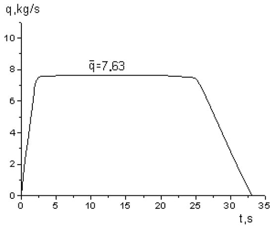
Figure 7.
Mass flow rate of the molten metal as a function of time during transient processes (initial and final).
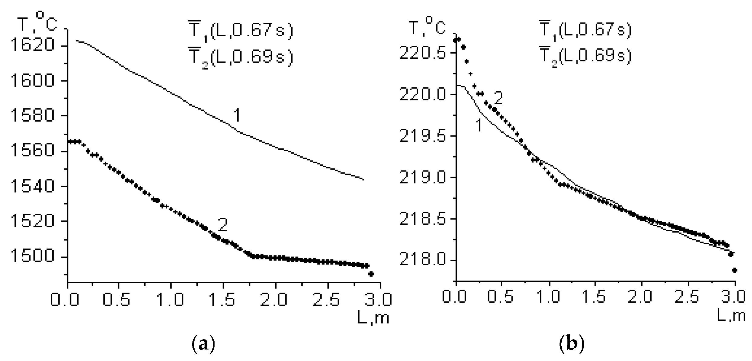
The temperature distribution in the casting is given at a filling thickness of the first metal layer of 0.001 m. Figure 8a shows the temperature distribution in the casting at initial temperatures = 1630 °C (curve 1) and = 1580 °C (curve 2), and Figure 8b shows the corresponding curves for the mold at = 218 °C.
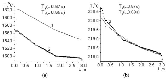
Figure 8.
Distribution of the average volume temperature at the BTS along the horizontal axis Z for a long casting. (a,b) temperature distribution.
This study contributes to the advancement of scientific knowledge by developing a physically grounded model of centrifugal casting that integrates hydrodynamics, heat transfer, and solidification. It reveals the relationships between technological parameters and casting quality, validated through experiments and thermal imaging. Future research may focus on 3D CFD simulations, microstructural modeling, and the application of machine learning for process optimization and automation.
5. Conclusions
- New data were obtained on the movement of the melt front along the axis of molding, as well as the release of gases at the hot end of the mold;
- Data were obtained on the transient processes (initial and final) during melt pouring;
- A generalized mathematical model was created in the dynamic system casting—the mold;
- Optimal parameters were experimentally obtained in centrifugal casting with a horizontal axis of short and long castings and evaluated using the created mathematical model.
Author Contributions
A.V., I.G., B.K. and K.P. declare that in terms of conceptualization, methodology, analysis, validation, writing, review and editing, and other activities necessary for the creation of this research scientific article, they worked as a team, and all have equal individual contributions. All authors have read and agreed to the published version of the manuscript.
Funding
This research received no external funding.
Institutional Review Board Statement
Not applicable.
Informed Consent Statement
Not applicable.
Data Availability Statement
Not applicable.
Conflicts of Interest
The authors declare no conflicts of interest.
References
- Tsvetnenko, K.U. Theoretical Foundations for Calculating the Rotation Speed of a Mold During Centrifugal Casting of Pipes; Metallurgy Publishing House: Kharkov, Ukraine, 1961; Volume VNITI, Issue 4. [Google Scholar]
- Oyewole, A.; Sunday, A.M. Design and fabrication of a centrifugal casting machine. Int. J. Eng. Sci. Technol. 2011, 3, 8204–8210. [Google Scholar]
- Zagorski, R.; Sleziona, J. Pouring mould during centrifugal casting process. Arch. Mater. Sci. Eng. 2007, 28, 441–444. [Google Scholar]
- Madhusudhan, S.N.; Kumar, G.; Mukunda, P. Experimental study on rate of solidification of centrifugal casting. Int. J. Mech. Mater. Eng. 2010, 5, 101–105. [Google Scholar]
- Bushev, S. Thermodynamic systems for heat treatment. In Proceedings of the II International Conference, Metal Science, New Materials, Hydro and Aerodynamics, Sofia, Bulgaria, 31 May–1 June 2012. [Google Scholar]
- Bushev, S.; Dimitrov, M.; Stoychev, N. Processes of martensite type phase transition of low rate. Nucleation kinetics models. In Proceedings of the National Conference with International Participation, Material Science and New Materials, Sofia, Bulgaria, 4–5 December 2008; pp. 288–293. [Google Scholar]
- Valkov, V.; Georgiev, I.; Bushev, S.; Dimitrov, M.; Stoichev, N. Mathematical Modeling. In Proceedings of the Anniversary Scientifically Conference International Participation MTF 2007, Sozopol, Bulgaria, 14–16 September; Volume 1, p. 9499.
- Georgiev, I.; Stanev, S.; Velikov, A. Centrifugal casting of nitrogen alloy billets with industrial application. In Scientific Notices of NTSM. Collection of Reports, International Conference, Days of Non-Destructive Testing 2012; British Institute of Non-Destructive Testing: Northampton, UK, 2012; Volume XX, pp. 183–186. [Google Scholar]
- Georgiev, I.; Valkov, V. Centrifugal casting of two-layer cast iron castings with a wear-resistant layer of ductile iron. In Scientific notices of NTSM, Collection of Reports. International Conference, Days of Non-Destructive Testing 2013; British Institute of Non-Destructive Testing: Northampton, UK, 2013; Volume XXI, pp. 428–431. [Google Scholar]
- Bushev, S.; Georgiev, I.; Valkov, V. Analysis of Vertical Axis Centrifugal Casting Technology for Bimetal Casting. Comptes Rendus L’académie Bulg. Sci. 2010, 63, 1117–1122. [Google Scholar]
- Daming, X.; Qingmei, Y.; Xin, L.; Geying, A. Mold filling behavior of melts with different viscosity under centrifugal force field. J. Mater. Sci. Technol. 2009, 18, 149–151. [Google Scholar]
- Barron, M.A. Analysis of molten metal distribution in the mold of a horizontal centrifugal casting. Open J. Apllied Sci. 2020, 10, 444–454. [Google Scholar] [CrossRef]
- Ebhota, W.S.; Karun, A.S.; Inambao, F.L. Centrifugal casting technique baseline knowledge, application, and processing parameters. Int. J. Mater. Res. 2016, 107, 1–10. [Google Scholar] [CrossRef]
- Mohapatra, S.; Sarangi, H. Effect of processing factors on the characteristics of centrifugal casting. EDP Sci. 2020, 7, 26. [Google Scholar] [CrossRef]
- Ivanov, P. Structural researching of the inner, primary supporting layer from ductile cast iron with a bimetallic roller shell with high—chrome material used as an external (working) layer, during a centrifugal casting method of production with a vertical axis. Int. J. Sci. Tech. Innov. Ind. Mach. Technol. Mater. 2022, 16, 41–43. [Google Scholar]
- Ivanov, P.; Georgiev, I.; Velikov, A. Structural investigation of high- chromium material used as an external, working layer of a bimetallic mill roller. ETR 2021, 1, 91–94. [Google Scholar] [CrossRef]
- Velikov, A.; Ivanov, P.; Georgiev, I. Structural Investigation of the Intermediate Layer in a Bimetal Mill Roller Produced by the Method of Vertical Axis Centrifugal Casting. ETR 2021, 1, 255–258. [Google Scholar] [CrossRef]

Disclaimer/Publisher’s Note: The statements, opinions and data contained in all publications are solely those of the individual author(s) and contributor(s) and not of MDPI and/or the editor(s). MDPI and/or the editor(s) disclaim responsibility for any injury to people or property resulting from any ideas, methods, instructions or products referred to in the content. |
© 2025 by the authors. Licensee MDPI, Basel, Switzerland. This article is an open access article distributed under the terms and conditions of the Creative Commons Attribution (CC BY) license (https://creativecommons.org/licenses/by/4.0/).