Abstract
This paper presents studies of a digital twin system. A conceptual model of the system is proposed to be used to control an industrial robot and can be integrated into different fields of application such as industry, manufacturing, farming, livestock breeding and others. On the principle of software engineering, the overall architecture of the system is developed, and its constituent elements are presented in detail. A kinematic analysis of the considered industrial robot is presented. To realize the digital twin, a simulation model of the industrial robot was developed to fully meet the dimensions and kinematic characteristics of the real one. Experiments have been made on the operation of the system so as to compare the movements of the real and simulated robot. The results obtained show almost identical motions both in the end effector of the robots and in the motions of each of the joints. A short methodology for the steps of creating systems using digital twins is presented to assist developers and scientists.
1. Introduction
Robotics is one of the most complex areas of research and is extremely widely used in all aspects of people’s lives. Since the beginning of their creation, robots have had the task of replacing and supporting human labor. With the development of science and technology, robots have improved and found very wide application in various fields, from industry and medicine to education and entertainment. In recent years, robots have also been widely used in areas such as animal husbandry and crop production [1]. Specifically with regard to animal husbandry, one of the most popular robots are those for milking cows [2,3,4,5]. In addition, robots are being researched and developed to automate processes such as feeding, watering, cleaning, servicing warehouse and production parts of farms, and others [6]. To robotize some processes, the digitalization of entire farms, animals, and pastures is applied.
Digitalization processes transform all actors in animal husbandry into simulated models [7]. Cyber-physical systems are created that use these simulated models to understand what is happening in the real world and to control the real environment. The created digital models are called digital twins, and their purpose is to reproduce the physical and behavioral characteristics of objects from the real world as much as possible. In general, the concept of digital twins is relatively new as an idea but is being explored and developed at a very fast pace [8]. One major reason for this is digitalization in general, and the great opportunities for fast, safe, and inexpensive experimentation in simulated environments.
Software engineering is an essential tool for the development and application of information technologies and systems in the age of digitalization [9]. By using mathematical methods and models, all physical and digital systems are developed and optimized. As a result of the significant development of digital technologies in recent years, new topics of research have emerged such as digital twins, digital methods for visualization, processing and analysis of data, various infrastructures, virtual and augmented reality, and others. All these methods and technologies are based on the idea of digitalizing physical objects in order to widely disseminate information, analyze and improve existing systems, methods, algorithms and solutions, applications in different fields, and facilitate learning and work processes [10].
With regard to robotics, the use of simulators has been an established practice for many years. But until recently, simulators were used to work entirely independently and offline from the real robot [11]. The role of these simulators for industrial robots, for example, is to prepare in advance the programs that the robot will perform, which are then uploaded to the real robot and tested again. Thanks to the concept of a digital twin, the simulated environment is now connected to the real one by exchanging data. This allows controlling objects and machines in the simulated environment to observe how this would affect the real environment and vice versa [12].
Digital twins make it possible to train staff, optimize processes, and reduce robot installation and programming time in production. These are the main benefits of applying the digital twin method when it comes to robotics. In recent years, the idea of using collaborative robots in production has evolved significantly. They improve some production processes that require human intervention. Thanks to these robots, we can reduce the workload on people and speed up processes such as assembling complex and heavy components, mount, and more. However, digital twins can also be used for industrial robots that are not collaborative. Through this method, operators will be able to very easily adjust the robots without the need to do many tests and adjustments. Also, it will easily be possible to reprogram different operations and optimize robots’ behavior [13].
A major technology for planning and optimizing processes of integration of collaborative robots in manufacturing is the “Digital Twin” [14]. Digital twins are becoming an increasingly used technology in manufacturing, cyber-physical systems, smart cities, and the Internet of Things. They are widely used in robotics and automation. With their contribution, the processes of installation and adjustment of the systems are accelerated [15,16]. Operators are given the opportunity to work in a safe environment and to develop their imagination, thinking, interactivity, creativity, and more.
In the literature, digital twins are presented as a virtual or simulated system that reproduces as accurately as possible the physical parameters of a real system [17]. This system is connected to the real world and data is exchanged between systems. In terms of robotics, digital twins present a simulated model that fully describes the physical parameters, actuators, and sensors used in a real robot.
According to a number of literary sources regarding digital twins, major problems are mentioned such as lack of methodology for the process of creating digital twin application systems [18,19]. There is also a lack of more general and universal solutions related to the application of digital twins in robotics. Another problem we can define is a lack of specifics in the development and application of various methods and algorithms for data processing, decision making and communication [8,10,13].
In this research, the aim is to investigate and design a conceptual model of a system for the realization of a digital twin of a robot. The tasks are related to the research and development of a communication system for connection between the different systems and modules, research and testing of a control module and algorithm for the operation and implementation of the digital twin, description and development of a simulation model, and development of methods and techniques for data transmission, processing, and visualization.
The idea is to develop a universal controller that can be applied to different systems of digital twins and real robots. In practice, all real robots have a control interface, many of them already have simulation models, but there is no detailed description of a module for a connecting link between a real robot and simulation. The main focus in this research concerns this problem: find the solution for controlling a real robot and its digital twin.
On the basis of the presented conceptual model and its components, a methodology will be presented that will represent the process of creation of a digital twin application system. As part of the methodology, some features are presented to support the processes of implementation and connection of the individual components of the entire system.
The study covers an industrial SCARA robot serving a rotary table and designed for operations such as picking and placement, packing, and palletizing. The robot will be part of a production process on a livestock farm or warehouse; it will pick up finished products from the rotary table and arrange it on a pallet or mobile robot. The ultimate goal is to create a digital twin of the entire farm so that some of the processes can be accelerated and heavy and monotonous work for some of the workers can be reduced. Software for simulating robots and other systems, such as Gazebo classic 11.0.0—software for controlling robots and other devices—ROS-Noetic, and software for backend development based on Python 3.8 were used to realize the research. A standard web socket protocol is used for the communication system, and the communication network is based on an ethernet connection.
The article is organized into the following chapters. Section 2 discusses in detail research related to digital twins, simulation of robots, software solutions, and architecture in complex systems. Section 3 presents the robot in detail, deriving its mathematical descriptions of the forward, inverse, and velocity kinematics. Then, a developed simulation model of the robot is presented. In Section 4, software solutions and implementations of mathematical models and test results of the simulated robot model are presented. In Section 5, a controller for connecting the real robot and the simulated robot has been investigated, and tests from their simultaneous operation are presented. Section 6 gives a short methodology describing the steps to create the digital twin application system.
2. Related Work
In [20], the authors describe an innovative approach that uses a collaborative robot to support intelligent inspection and corrective actions for quality control systems in the manufacturing process, complemented by an intelligent system that learns and adapts its behavior according to the inspected parts. The method is based on the Reinforced Self-Learning and the Actor-Critic method. The authors achieve a result that allows a person to train a movement on a set path. But here the elements of adaptability are lacking, and no mention is made of risks from the point of view of safety.
Safety is also a major problem in another study [21]. Here, the authors present a simulation environment for testing different scenarios. Also presented is an algorithm to ensure safe movement of a manipulator while there is a person nearby.
In another study, the authors used Reinforced Self-Learning in combination with Digital Gemini [22]. They present a simulated model of a collaborative robot they train. The authors have made significant contributions to the way data is transmitted between the real and digital robots. With them, the problem of training remains significant, and although they are successful in it, many settings of parameters and algorithms are still required.
Speed and separation monitoring (SSM) allows operator protection in collaborative robot applications by maintaining a certain minimum separation distance during operation. A continuous adaptation of the robot speed in response to the relative motion of the operator and the robot can be used to improve the efficiency of SSM-type applications [23].
In [24], an overview of industrial cooperation scenarios and programming requirements for cobots for the implementation of effective cooperation is presented. Methods of cobot programming, which are categorized into communication, optimization, and training, are discussed in detail. In addition, a significant gap between cobot programming applied in industry and in research has been identified.
Turning to software problems, we can pay attention to the digital twin method. It is often used for training and experiments. In a number of studies, they applied this method [25,26,27]. A digital twin (DT) is a digital representation of both the components and the dynamics of a physical system, thanks to advances in virtualization, sensor technology and computing power. Here, the problems are mainly related to informatics and various methods of processing, presentation of data, as well as visualization methods. In some studies, augmented reality has been presented as an aid to human–robot collaboration [28]. Four types of human–robot collaboration are currently known [29]: Observed braking with safety rating, Manual operator guidance, Speed and separation monitoring, and Power and force limitation. All these methods have different applications but are not enough on their own to cover the requirements. Therefore, combinations of methods and complex systems solving safety problems are sought.
There are a number of studies using different simulators and systems for digital twins. Azure Digital Twins is one of several available platforms for creating and managing twin digital models, but it has several features that set it apart from other options: Azure Digital Twins is built on top of the Azure IoT platform, which means it has native integration with other Azure services such as Azure IoT Hub, Azure Stream Analytics, and Azure Data Explorer. This can facilitate the connection of twin digital models to physical devices and systems, as well as the analysis and visualization of data from these devices and systems [30]. Azure Digital Twins also includes support for spatial intelligence. This means that it can be used to create 3D models of physical spaces and to analyze and visualize data. The spatial intelligence function allows for a more accurate representation of the real world and allows more detailed analysis of data collected by IoT devices.
In the research by [31], the use of simple force monitoring solutions to guide the automatic generation of a polishing instrument trajectory without resorting to CAM techniques was explored. The work is aimed at industrial applications. A force monitoring device was simulated and developed using off-the-shelf components and a rotating spindle used on an industrial robot. The research is based on simulations at ABB’s RobotStudio and other internally developed software. The results are tested using an industrial robot ABB IRB1600 to verify their feasibility for polishing operations for the tool industry.
The number of industrial robots and the type of industrial applications for which they are used, such as assembly operations, has increased significantly over the past few decades. However, programming continues to be a task that requires a high level of technical knowledge and takes a lot of time. In [32], a methodology is proposed to perform part assembly operations using Learning by Demonstration (LbD) techniques, such as TP-GMM (parameterized Gaussian Mixture Model). Task demonstrations were performed by a human and were visually obtained using a Kinect motion sensor. Later they were used to train probabilistic models. Petri nets were used to automatically generate mounting plans from those parts discovered by Kinect. Finally, operations were simulated in the RobotStudio ® Suite software and later performed by an IRB 140 robot, manufactured by ABB. The results obtained show that it is possible to use programming techniques which are different from traditional methodology such as LbD to obtain satisfactory results in generating trajectories for simple assembly operations.
Omniverse Enterprise is a complete 3D design and simulation platform optimized and certified by NVIDIA to work on NVIDIA-Certified™ systems. In [33], they propose a method which allows interactive, high-quality visualization of simulation geometry. Omniverse is NVIDIA’s collaboration platform for 3D production lines. It is integrated with a number of commercially available 3D software packages and game engines and allows content creators to work on different aspects of models or entire scenes simultaneously.
Learning factories demonstrate applications and technologies to students in a real industrial environment. Although variable turnkey learning factories are supplied by many suppliers, with some digital twin capabilities, they are mostly a closed box, with very little flexibility to change the underlying architecture or technology, which prevents the maximum benefit of the students’ hands-on experience. In [34], the paper presents a method to build a simulated variable training factory and connect it to the physical digital twin creation system. The study training factory (LEAF) is an inexpensive and variable automated open-source system. The proposed digital environment is “RoboDK”, which is a 3D simulation and offline/online programming environment, mainly for industrial robots, but also offers an open-source programming Python library, allowing an extension of the software capabilities for adaptation. The method also uses the industrial open-source communication protocols Modbus TCP and OPC UA to establish a link between physical modules and digital objects. The results show a capable numerical system that accurately reflects the layout of the physical system and the material flow, with a flexible structure allowing future expansions.
In another study, the Gazebo simulator was used, with the authors describing a machine learning-based symbolic regression approach for the synthesis of a mobile robot stabilization system [35]. The simulator was used to simulate a mobile robot and extract data from the simulated environment. In other studies, the authors are concerned with the modeling and simulation (M and S) of missile guidance systems and methods, in particular, line-of-sight beam guidance (LOSBR) and passive homing (PH) guidance in a WEBOTS robot simulation environment [36].
3. Robot Description
To control the robot, its kinematic descriptions must be used. In this way, the motion laws of each of the joints are set in the control software and trajectory movements can be generated. The robot under consideration is a type of SCARA manufactured by Fanuc. In Figure 1, one illustrates the kinematic scheme of the robot provided by the manufacturer. Its physical parameters are presented in Table 1.
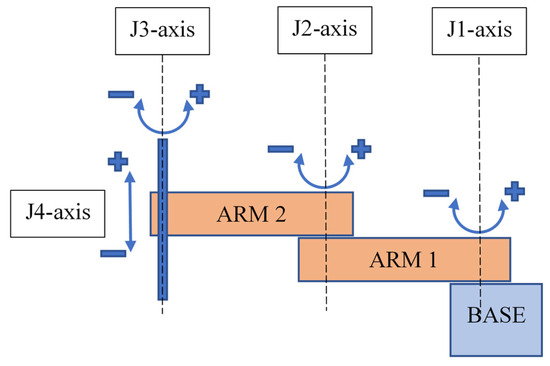
Figure 1.
SCARA robot description.

Table 1.
Range of motion and speeds for each axle.
3.1. Forward Kinematics
The forward kinematics of a robot is expressed in determining the position and orientation of the frame of its end-effector from the coordinates of the joints θ. Figure 2 illustrates the problem of forward kinematics of the robot under consideration. We have to solve a problem of a planar system with two degrees of freedom. The lengths of the links are and . We select a zero fixed frame {S} with a beginning localized on the base joint (equal to frame {0} in Figure 2) and set the frame of the end effector {B} (equal to frame {3} in Figure 2). The cartesian position (x, y) and orientation of the end-effector as a function of joint angles () are calculated as:
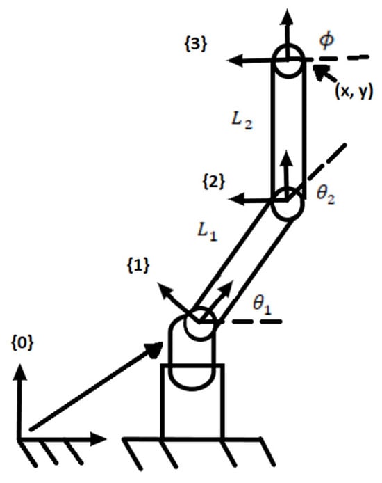
Figure 2.
Forward kinematics problem.
In this study, we consider only the position of the end effector and exclude its orientation, therefore we will only use Equations (1) and (2).
Finding the forward kinematics through the initial frame and the end frame will have the following form:
where is the frame configuration of the end effector when the robot is in zero position (Figure 3).
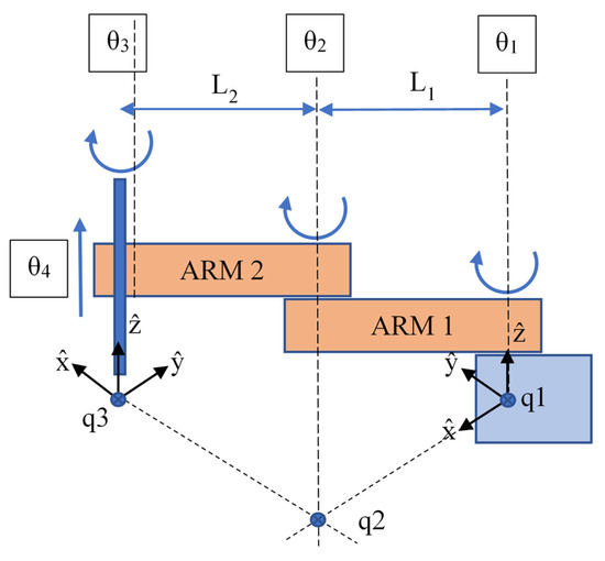
Figure 3.
Detailed robot kinematics.
To solve the forward kinematics, we need to find the matrix M, the robot configuration relative to frame {B} and the angles of rotation of the joints when the arm is in zero configuration. We are looking for M, S1... S4, or B1... B4. We find M:
- For a first column—Relative to x frame {B} is aligned with minus y by frame {S}.
- For a second column—Relative to y frame {B} is aligned with minus x by frame {S}.
- For a third column—Relative to z frame {B} is aligned with minus z by frame {S} and we have an offset of 65 (L1 + L2) units on the x-axis.
It is necessary to find the angles of rotation of each joint relative to frame {S} and frame {B}. For joint 1, we have the following dependencies. With respect to frame {S}, the angle of rotation coincides with the z-axis and so the angular component of S1 is [0 0 1]. Rotation about this axis does not cause linear motion at the base of frame {S}, therefore the linear component of the screw is [0 0 0].
We can also express the screw axis as B1 in frame {B}. The axis of the joint is in the negative direction relative to zb, so the angular component is [0 0 −1]. The unit angular velocity about the j1 axis induces a linear velocity at the point at the beginning of frame {B} and it is seen that this linear velocity is 65 units in the minus xb direction.
3.2. Velocity Kinematics
To control the robot by acceleration, the Jacobi matrix must be derived [37]. To find the Jacobi for the robot under consideration, we use Figure 2. The general appearance of the Jacobi matrix is deduced from the following dependencies. Let us consider that the end-effector configuration is represented by a minimum set of coordinates, and the velocity is given by . In this case, the forward kinematics can be written as:
where is a set of joint variables. By the circuit rule the derivative at time t is
where is the Jacobi matrix.
Denote the i-th column of with . The matrixes are implicit in our calculations of the screw axes of the joints.
- -
- We note that is constant and in the direction : Choose as starting point,
- -
- is also a constant in direction , so . Choose as point , where , . Then .
- -
- The direction of is always fived in , regardless of the values of and , so . Choose , where , it follows that .
- -
- Since the final relationship is prismatic, and the direction of the joint is determined by .
The Jacobi space is therefore:
3.3. Inverse Kinematics
For a common open circuit with n number of degrees of freedom , the inverse kinematics problem is as follows: a homogeneous transformation is given , to find solutions , those who satisfy . We consider Equations (1) and (2) for a two-link robot and are only interested in the position of the end-effector (Figure 4). For our robot, where , the set of reachable points (i.e., the workspace) forms a ring with an inner radius of and an outer radius . Given the extreme position of the effector (x, y), it is not difficult to see that there will be either zero, one, or two solutions depending on whether (x, y) lies in the outer, boundary, or inner part of this ring, respectively. When there are two solutions, the angle of the second joint can be positive or negative. These two solutions are sometimes called “left” and “right” solutions or “elbow up” and “elbow down” solutions.
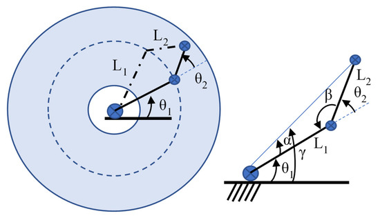
Figure 4.
Analysis of the inverse kinematics.
Finding an explicit solution (, ) for a given (x, y) is next step. For this purpose, we will find it useful to introduce the arctangent function with the two arguments , which return the angle from the origin to a point (x, y) in the plane. It is similar to the inverse tangent , but while is equal to , and therefore returns only angles in a range (−π/2, π/2), the function returns angles in the range of (−π, π). For this reason, is sometimes called a four-quadrant arctan.
Let us consider the law of cosines,
where a, b, and c are the lengths of three sides of a triangle and C is the inner angle of the triangle opposite the side c. Using Figure 3, angle beta is limited in the interval [0, π], and can be determined from the following equation:
From which it follows that
The gamma angle is determined using the arctangent functions with two arguments, . With these angles, the righty solution of the inverse kinematics is:
And the lefty solution is:
If is out of range , then there is no solution.
4. Simulation Model of the Robot and Control
In robotics, it is important to build a correct mechanical model of the robot with the corresponding link lengths and inertial characteristics, joint positions, and joint orientation with a correct coordinate system. Additionally, in order to obtain a realistic simulation, the mass of each link and its inertial parameters must be introduced. These parameters are the basis of building any single robot simulation and are used for a dynamic model of the robot.
4.1. Construction of a Simulation Model at Gazebo
We have already mentioned that the simulation model will be implemented in the Gazebo simulator. For this purpose, the structure of the robot must be kinematically presented, all the constituent links must be defined and the joints between them must be defined. In this situation, we have a robot with four links and four joints. The base link is attached to the middle (in black). It is fixed and does not move. Link 1 is connected to the base link through joint 1. In this connection we have a rotation of the link L1 relative to the Z-axis which is directed upwards. In green, it is represented joint 1, in yellow, there are both shoulders, in red, joint 2, and in blue, joint 3. In the presented model we exclude joint 4, at least we consider control of the robot without end-effector.
Between link 1 and link 2 is located joint 2. Here, link 2 rotates around the Z axis of the joint, which is also oriented upwards. The third joint is prismatic and lies between link 2 and the axis of the end effector. The developed simulation model in the Gazebo simulator is presented in Figure 5.
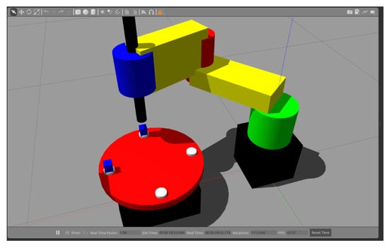
Figure 5.
Developed simulation model of the SCARA robot and the rotary table.
In the code describing the links and joints of the robot, we have several features. The description of the links includes geometry, inertial parameters and collision of the given link. To realize the kinematics correctly, the rule of distance between the centers of individual joints must be observed to be according to Table 1. Therefore, the length of the link is 0.350 m. In the specific example, the second arm of the robot is given in Figure 6. With regard to geometry and collision, the shape and dimensions of the object, as well as its orientation, are given. By default, the Z axis is always up, but in this case, we have to rotate the link so that Z points to joint 3 (line 7 and 19 of the code). In the inertial parameters, the mass of the link is set to row 10 and inertia parameters according to the shape of the workpiece, line 12.
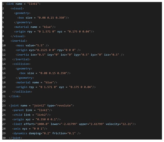
Figure 6.
Robot description in URDF file.
The description of the joints includes the setting of parental and child links, position and orientation of the connection between them, type of drive, dynamic characteristics, and speeds and limits of movement. All these parameters are presented in rows 23 to 30. Here, attention should be paid to the speed parameter, which is taken from Table 1. Once the overall structure of the robot is formed, simulated actuators must be added to represent the real motors. In the code below (Figure 7), an example of controller and actuator definition at joint 2 is presented. In this way, a simulation of a hardware device that can be controlled as an electric motor is created.

Figure 7.
Robot actuators parameters in the URDF file.
To control the created actuators and transmissions, plugins from the Gazebo library must be integrated. In our simulation we use two plugins. Gazebo controller plugin, which provides the ability to use speed and position control regulators. Gazebo camera plugin, which simulates a camera with parameters such as resolution and frame rate. Detailed information about setting up plugins can be found on the official website of Gazebo.
4.2. Implementation of Joint Controllers
The ROS offers a large set of packages for control, data visualization and processing. We will use a PID controller to control the movement of joints by speed and direction. The settings for each joint are stored in a configuration file with the extension ‘.yaml’. In this file separately for each joint, the values of the P, I and D components from each controller are described. To adjust the parameters correctly, a special tool rqt_gui can be used. It can visualize current nodes and topics, data from ROS topics, publish data in topics and set up controllers. Changes made to the settings of a controller are automatically updated in the configuration file.
The purpose of tuning the controllers is to achieve the same movement of the simulated robot and the real one as accurately as possible. For this purpose, each of the joints is adjusted correctly. The presented graphs visualize the results of the settings and behavior of each of the robot joints when rotating in both directions; they also show the control of the rotary table are shown in Figure 8, Figure 9 and Figure 10 respectively. The joint control results presented are for joints 1 and 2 and for the rotary table. On all graphics, the same color legends are used as follows: in blue is the value of the control signal, in black is the set position and in red is the moment error.
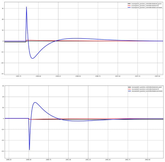
Figure 8.
Joint 1 position control output.
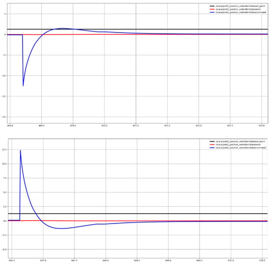
Figure 9.
Joint 2 position control output.
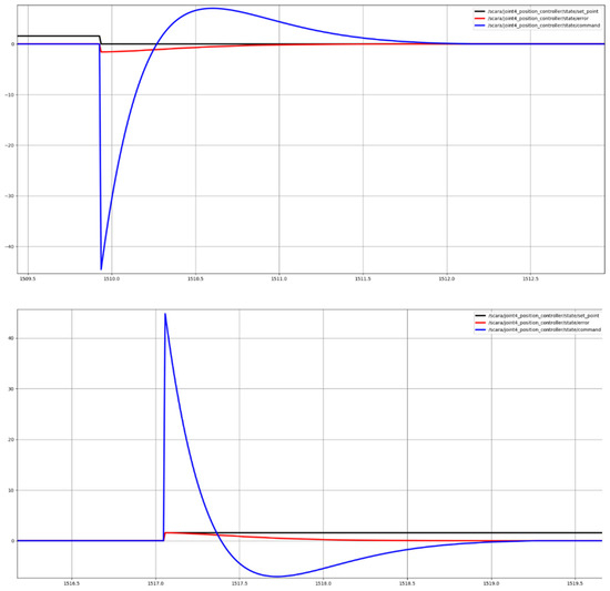
Figure 10.
Rotary table position control output.
4.3. Cartesian Coordinates Control
The industrial robot has different control modes. To make a fully functional digital twin, we need to recreate all these modes. This means using the forward and inverse kinematics and implementing them in programming code. For this purpose, ROS nodes and services have been developed to control the robot according to Cartesian coordinates. This means that we can set a desired position on which to drive the end-effector. The overall software structure of ROS nodes, topics and services is illustrated in Figure 11.
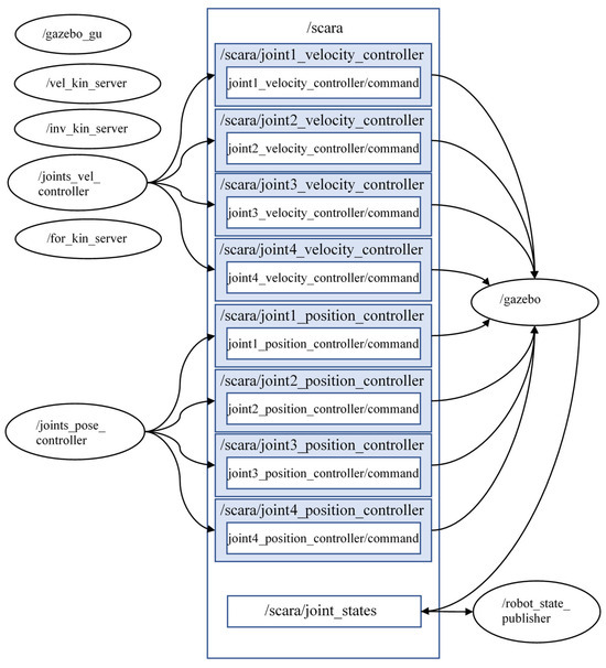
Figure 11.
ROS based software architecture.
The derived mathematical equations for the line, inverse and velocity kinematics are described in separate programs and can be called as necessary. They operate in the form of services. They also introduce positioning restrictions, and check for a valid desired position. The control of the simulated robot is also carried out by using a service. This service obtains as input arguments the position of the end effector in Cartesian coordinates as well as its displacement up and down the Z-axis. The service call form is “x: 0.0 y: 0.0 z: 0.0”, each parameter representing a floating-point number. The developed service invokes joint_pose_controller and joint_vel_controller nodes until the desired position is reached.
5. Controller for the Management of the Robot and the Digital Twin
The system implements the control of both the real robot and the digital twin in real time. In addition, different interfaces and tools for human–robot interaction can be developed. Given the specificity and needs of the digital twin method, the scheme in Figure 12 is presented. It shows the general structure and manner of transmission of data between the individual participants.
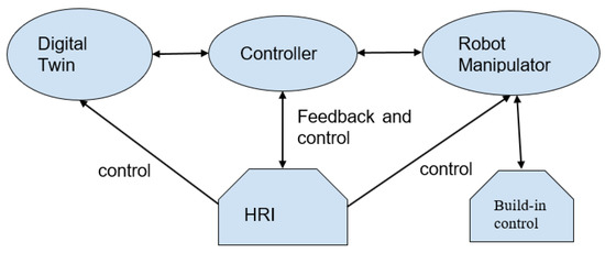
Figure 12.
General overview of the proposed system for digital twin control.
In the center of the system stands the main controller. Its task is to make the connection between the real robot and the simulated robot in real time. It connects to the real robot by using a standard Modbus protocol. On the other side, it connects to the digital twin via web sockets. In the controller itself, a comparison of the current positions of each of the robot joints as well as of the current speeds occurs. As standard in industrial robots, the speed is set as a percentage. Therefore, the set speed here is measured in percentages. The initial form of the data for joint positions are presented in Figure 13a,b. Entering the controller, the data from the digital twin is rounded to the second character after the comma and compared with that of the real robot. In addition, to find out in which of the systems there has been a change, we use time data. We compare which action occurred first, then commands are sent to move the system where no action is registered.

Figure 13.
Received data packages from the robots.
Behind the whole process is an algorithm to control the entire system. It also receives data from an operator. According to the source of the received data, a decision is made to take a specific action. If control comes from the operator side, commands are sent to both robots; if it comes from one robot, commands are sent to the other robot and to the operator interface. As can be seen from Figure 12, each robot can have a separate control interface, which is mandatory for any industrial robot.
The detailed appearance of the controller is presented in Figure 14. From right to left, data from the real robot is received and transmitted to the digital twin. From left to right is the reverse communication, and is added here to ensure security additional controller. It validates the input data and limits the speed to the real robot if very high speeds are received in the simulated one, greater than 80%. The idea of this controller is to expand the functions of the robot to work with people in an environment and to transform it into a collaborative one. Another important component in the controller is the diagnostic data of the real robot. If there is a problem, this data is sent to the digital twin and to the control interface. Thus, the operator will know about the presence of malfunctions.
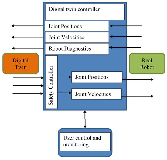
Figure 14.
Detailed structure of the system controller.
Description of the Principle of Operation of the System
This is an example scenario to show how the system operates in real time. We assume that an operator has programmed the real robot to make movement at cartesian coordinates within the range of the rotary table and has loaded the execution of this program from the built-in control panel of the robot. In this program, two positions are set for the end effector and the robot speed for each of the two directions of movement. As soon as the robot’s operation starts, the main controller receives movement data of the real robot. The data is formed in a single package, which contains the type of control of the robot, the speed used, and the current positions of each joint.
Receiving this data, the controller sends the same to the digital twin, using the developed services and nodes. It calls the services and as arguments, publishes the last received positions from the real robot. As feedback, it receives the current positions of the digital twin, which are with a later time than the real one. In this way, a continuous process is obtained, because new data is constantly coming in from the real robot with a later time. This continues until the actual robot is terminated. The controller also receives data for commands such as ‘STOP’, ‘PAUSE’, and others. These commands are duplicated and can be sent by the controller to the real robot. In this way, the two-way control of both robots is realized.
Two types of experiments have been conducted to test the performance of the system in real conditions. One type is according to the example described: we control the real robot and observe the reactions of the digital twin. The second type is backwards: we control the digital twin and observe the real robot. The experiments start from the initial robot position which coincides with the position of the front from the stands of the rotary table (seen from the robot side), and the position of the end effector is x: 0.65, y: 0.0, z: 0.0. Initially, a position is set above the left stand of the rotary table, then a position above the right stand, and finally a position above the rear stand. In this way, the ability of the digital twin to pick up and place objects on the table will be checked. The reference job coordinates for each end-effector position are as follows: position 1—x: 0.65, y: 0.0, z: 0.0; position 2—x: 0.51, y: 0.16, z: 0.10; position 3—x: 0.51, y: −0.16, z: 0.16.
The results obtained from the experiments for the executed end-effector positions are presented in Figure 15. We can see the described trajectories from the real robot and the digital twin. Here we can say that the measured error during movement from the described trajectories is in the order of up to 5%, comparing the recorded data from both systems. The positioning accuracy error when the set positions are reached is 2% between the two robots.
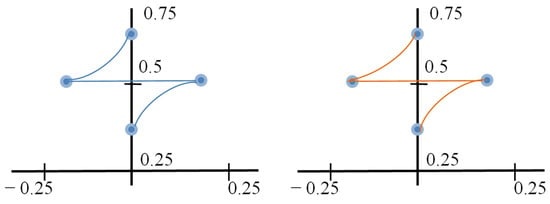
Figure 15.
The results from the cartesian control of the and-effector.
With respect to the positions of each of the joints during movement of the two systems in the following Figure 16, the recorded positions of each of the joints until the assignment is reached.
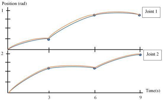
Figure 16.
Joint 1 and Joint 2 movement during robot motion.
From the obtained results, we see the minimal discrepancy in the position of the joints of the real robot and of the digital twin. In blue are represented the movements performed by the real robot, and in yellow, those by the digital twin. During movement, there is a slight shift in position due to real-time operation and the small time delay due to the communication system. Operating in this way, we can say that the proposed system satisfies the requirements for time delay and accuracy.
6. Process Methodology for the Development of Digital Twin Systems
As mentioned in the introduction, there are a small number of studies detailing a methodology for developing systems using digital twins. In this section, we briefly present our methodology based on software engineering methods such as software architecture, data exchange, software levels, software frameworks, and more.
We can separate several main aspects of the design process:
- Parameters and characteristics of the real robot;
- System-wide software architecture;
- Communication system for data and signal transmission;
- Software for implementing the digital twin.
In terms of the real robot:
- The mechanics and kinematics of the robot must be known in detail;
- All the output data that is used to control the robot must be determined;
- The communication protocols for data exchange with the robot must be defined.
In terms of software architecture:
- Define frameworks for using ready-made applications;
- Definition of data formats and communication protocols;
- Definition of programming languages for the application of software development.
In terms of the communication system:
- Definition of network protocols;
- Definition of network devices to realize the physical layer;
- Definition of interface communication links between the individual elements of the system.
In terms of simulation:
- Development of a complete analog of the real robot in terms of kinematics, mechanics, design;
- Development of software sensors and actuators to reproduce the real;
- Definition of a communication protocol
The steps presented briefly aim to facilitate the process of developing a complete system for working with digital twins. Each stage of development requires in-depth knowledge in the field of software engineering, information and communication technologies.
7. Conclusions
The digital twin method is useful for speeding up the processes of work in practice and science. This method can significantly contribute to the optimization of various algorithms and methods, but the creation of systems that use digital twins requires in-depth knowledge in the field of software engineering, computer science and other areas of education and science.
This research covered the entire process of developing and researching a digital twin system with industrial robot control. The proposed model of a control system for the digital twin and the real robot was implemented in a real environment and the results obtained from the experiments showed that the system fulfills the condition to simultaneously control the digital twin and the real robot. It enables the exchange of data between the systems of the two robots and to register changes in real time. The presented system can be integrated into different production processes and connected to more complex cyber-physical systems using web-based technologies and standard communication protocols.
Author Contributions
Conceptualization, D.C. and K.Y.; methodology, D.C. and S.T.; software, K.Y. and S.T.; validation, V.I., K.Y. and D.C.; formal analysis, K.Y. and D.C.; investigation, K.Y. and D.C.; resources, D.C.; writing—original draft preparation, D.C.; writing—review and editing, D.C. and K.Y.; visualization, V.I.; supervision, S.T.; project administration, D.C.; funding acquisition, D.C. All authors have read and agreed to the published version of the manuscript.
Funding
This work was accomplished from the Center for Competence in Mechatronics and Clean Technologies–MIRACle, with financial support from Grant No. BG16RFPR002-1.014-0019-C01 and Grand No. BG16RFPR002-1.014-0004, financed by the Program “Research, Innovation, and Digitalization for Smart Transformation” (PRIDST) 2021–2027.
Data Availability Statement
The original data presented in the study are openly available in Github: scara_sim at https://github.com/Chikurtev/scara_sim (Accessed on 7 July 2025).
Conflicts of Interest
The authors declare no conflicts of interest.
References
- Karastoyanov, D.; Blagoeva, E.; Yarkov, D. Innovations in Robotic Animal Husbandry. In Proceedings of the 2022 26th International Conference on Circuits, Systems, Communications and Computers (CSCC), Crete, Greece, 19–22 July 2022; pp. 300–303. [Google Scholar]
- Kuczaj, M.; Mucha, A.; Kowalczyk, A.; Mordak, R.; Czerniawska-Piątkowska, E. Relationships between Selected Physiological Factors and Milking Parameters for Cows Using a Milking Robot. Animals 2020, 10, 2063. [Google Scholar] [CrossRef] [PubMed]
- Winnicki, S.; Romaniuk, W.; Mielcarek-Bocheńska, P.; Borusiewicz, A.; Barwicki, J. Efficiency of Milking Cows Using Robot in a Large Herd. Agric. Eng. 2019, 23, 87–101. [Google Scholar] [CrossRef]
- Vinogradova, N.D.; Paderina, R.V. Efficiency of application of automatic milking systems (AMS). Leg. Regul. Vet. Med. 2022, 53–56. (In Russian) [Google Scholar] [CrossRef]
- Boloña, P.S.; Upton, J.; Cabrera, V.; Erker, T.; Reinemann, D. Simulation model of quarter milk flowrates to estimate quarter and cow milking duration and automated milking system’s box duration. J. Dairy Sci. 2022, 105, 4156–4170. [Google Scholar] [CrossRef] [PubMed]
- Coleman, K.; Timmel, G.; Prongay, K.; Baker, K.C. Common Husbandry, Housing, and Animal Care Practices. In Nonhuman Primate Welfare; Robinson, L.M., Weiss, A., Eds.; Springer: Cham, Switzerland, 2023. [Google Scholar] [CrossRef]
- Mu, M.; Zhou, Y.; Wu, D. Digital Twins on Animal Husbandry: Insights and Application. Procedia Comput. Sci. 2022, 214, 1182–1189. [Google Scholar] [CrossRef]
- Fuller, A.; Fan, Z.; Day, C.; Barlow, C. Digital Twin: Enabling Technologies, Challenges and Open Research. IEEE Access 2020, 8, 108952–108971. [Google Scholar] [CrossRef]
- Broy, M. The Leading Role of Software and Systems Architecture in the Age of Digitization. In The Essence of Software Engineering; Gruhn, V., Striemer, R., Eds.; Springer: Cham, Switzerland, 2018. [Google Scholar] [CrossRef]
- Gebhart, M.; Giessler, P.; Abeck, S. Challenges of the digital transformation in software engineering. In Proceedings of the ICSEA 2016: The Eleventh International Conference on Software Engineering Advances, Rome, Italy, 21–25 August 2016; p. 149. [Google Scholar]
- Urrea, C.; Pascal, J. Design, simulation, comparison and evaluation of parameter identification methods for an industrial robot. Comput. Electr. Eng. 2018, 67, 791–806. [Google Scholar] [CrossRef]
- Garg, G.; Kuts, V.; Anbarjafari, G. Digital Twin for FANUC Robots: Industrial Robot Programming and Simulation Using Virtual Reality. Sustainability 2021, 13, 10336. [Google Scholar] [CrossRef]
- Hoebert, T.; Lepuschitz, W.; List, E.; Merdan, M. Cloud-Based Digital Twin for Industrial Robotics. In Industrial Applications of Holonic and Multi-Agent Systems. HoloMAS 2019; Lecture Notes in Computer Science; Springer: Cham, Switzerland, 2019; Volume 11710. [Google Scholar] [CrossRef]
- Javaid, M.; Haleem, A.; Suman, R. Digital Twin applications toward Industry 4.0: A Review. Cogn. Robot. 2023, 3, 71–92. [Google Scholar] [CrossRef]
- Garvanov, I.; Garvanova, M.; Borissova, D.; Vasovic, B.; Kanev, D. Towards IoT-based transport development in smart cities: Safety and security aspects. In Business Modeling and Software Design. BMSD 2021; Lecture Notes in Business Information Processing; Shishkov, B., Ed.; Springer: Cham, Switzerland, 2021; Volume 422, pp. 392–398. [Google Scholar] [CrossRef]
- Garvanov, I.; Garvanova, M. New Approach for Smart Cities Transport Development Based on the Internet of Things Concept. In Proceedings of the 2021 17th Conference on Electrical Machines, Drives and Power Systems (ELMA), Sofia, Bulgaria, 1–4 July 2021; pp. 1–6. [Google Scholar] [CrossRef]
- Tao, F.; Zhang, H.; Liu, A.; Nee, A.Y.C. Digital Twin in Industry: State-of-the-Art. IEEE Trans. Ind. Inform. 2018, 15, 2405–2415. [Google Scholar] [CrossRef]
- Schroeder, G.N.; Steinmetz, C.; Rodrigues, R.N.; Henriques, R.V.B.; Rettberg, A.; Pereira, C.E. A Methodology for Digital Twin Modeling and Deployment for Industry 4.0. Proc. IEEE 2020, 109, 556–567. [Google Scholar] [CrossRef]
- Aivaliotis, P.; Georgoulias, K.; Arkouli, Z.; Makris, S. Methodology for enabling Digital Twin using advanced physics-based modelling in predictive maintenance. Procedia CIRP 2019, 81, 417–422. [Google Scholar] [CrossRef]
- Brito, T.; Queiroz, J.; Piardi, L.; Fernandes, L.A.; Lima, J.; Leitão, P. A Machine Learning Approach for Collaborative Robot Smart Manufacturing Inspection for Quality Control Systems. Procedia Manuf. 2020, 51, 11–18. [Google Scholar] [CrossRef]
- Kaonain, T.E.; Rahman, M.A.A.; Ariff, M.H.M.; Yahya, W.J.; Mondal, K. Collaborative robot safety for human-robot interaction in domestic simulated environments. IOP Conf. Ser. Mater. Sci. Eng. 2021, 1096, 012029. [Google Scholar] [CrossRef]
- Matulis, M.; Harvey, C. A robot arm digital twin utilising reinforcement learning. Comput. Graph. 2021, 95, 106–114. [Google Scholar] [CrossRef]
- Byner, C.; Matthias, B.; Ding, H. Dynamic speed and separation monitoring for collaborative robot applications—Concepts and performance. Robot. Comput. Manuf. 2019, 58, 239–252. [Google Scholar] [CrossRef]
- El Zaatari, S.; Marei, M.; Li, W.; Usman, Z. Cobot programming for collaborative industrial tasks: An overview. Robot. Auton. Syst. 2019, 116, 162–180. [Google Scholar] [CrossRef]
- Bilberg, A.; Malik, A.A. Digital twin driven human–robot collaborative assembly. CIRP Ann. 2019, 68, 499–502. [Google Scholar] [CrossRef]
- Malik, A.A.; Brem, A. Digital twins for collaborative robots: A case study in human-robot interaction. Robot. Comput. Manuf. 2021, 68, 102092. [Google Scholar] [CrossRef]
- Kousi, N.; Gkournelos, C.; Aivaliotis, S.; Giannoulis, C.; Michalos, G.; Makris, S. Digital twin for adaptation of robots’ behavior in flexible robotic assembly lines. Procedia Manuf. 2019, 28, 121–126. [Google Scholar] [CrossRef]
- Masood, T.; Egger, J. Augmented reality in support of Industry 4.0—Implementation challenges and success factors. Robot. Comput.-Integr. Manuf. 2019, 58, 181–195. [Google Scholar] [CrossRef]
- Vysocky, A.L.E.S.; Novak, P.E.T.R. Human-Robot collaboration in industry. MM Sci. J. 2016, 9, 903–906. [Google Scholar] [CrossRef]
- Khaled, N.; Pattel, B.; Siddiqui, A. Digital Twin Development and Deployment on the Cloud; Elsevier: Amsterdam, The Netherlands, 2020; ISBN 978-0-12-821631-6. [Google Scholar] [CrossRef]
- Afonso, D.; Guincho, R. On the development of an haptic tool based autonomous polishing system. Procedia Manuf. 2019, 41, 430–436. [Google Scholar] [CrossRef]
- Duque, D.A.; Prieto, F.A.; Hoyos, J.G. Trajectory generation for robotic assembly operations using learning by demonstration. Robot. Comput. Manuf. 2019, 57, 292–302. [Google Scholar] [CrossRef]
- Hummel, M.; van Kooten, K. Leveraging NVIDIA Omniverse for In Situ Visualization. In High Performance Computing; ISC High Performance 2019; Lecture Notes in Computer Science; Weiland, M., Juckeland, G., Alam, S., Jagode, H., Eds.; Springer: Cham, Switzerland, 2019; Volume 11887. [Google Scholar] [CrossRef]
- Al-Geddawy, T. A Digital Twin Creation Method for an Opensource Low-cost Changeable Learning Factory. Procedia Manuf. 2020, 51, 1799–1805. [Google Scholar] [CrossRef]
- Shmalko, E.; Rumyantsev, Y. Synthesis of a Feedback Controller by the Network Operator Method for a Mobile Robot Rosbot in Gazebo Environment. Eng. Proc. 2023, 33, 6. [Google Scholar] [CrossRef]
- Starý, V.; Gacho, L. Modelling and simulation of missile guidance in WEBOTS simulator environment. In Proceedings of the 2020 19th International Conference on Mechatronics-Mechatronika (ME), Prague, Czech Republic, 2–4 December 2020; pp. 1–5. [Google Scholar] [CrossRef]
- Lynch Kevin, M.; Frank, C.P. Modern Robotics; Cambridge University Press: Cambridge, UK, 2017. [Google Scholar]
Disclaimer/Publisher’s Note: The statements, opinions and data contained in all publications are solely those of the individual author(s) and contributor(s) and not of MDPI and/or the editor(s). MDPI and/or the editor(s) disclaim responsibility for any injury to people or property resulting from any ideas, methods, instructions or products referred to in the content. |
© 2025 by the authors. Licensee MDPI, Basel, Switzerland. This article is an open access article distributed under the terms and conditions of the Creative Commons Attribution (CC BY) license (https://creativecommons.org/licenses/by/4.0/).