Proceeding Paper

Analysis of Natural Vaporization in LPG Tanks †

Faculty of Engineering, University of Rijeka, 51000 Rijeka, Croatia
*
Author to whom correspondence should be addressed.
Presented at the 5th International Electronic Conference on Applied Sciences (ASEC 2024), 4–6 December 2024; Available online: https://sciforum.net/event/ASEC2024.
Eng. Proc. 2025, 87(1), 98; https://doi.org/10.3390/engproc2025087098
Published: 23 July 2025
(This article belongs to the Proceedings of The 5th International Electronic Conference on Applied Sciences)

Abstract

Natural vaporization in LPG (liquefied petroleum gas) tanks refers to the process where liquid LPG is converted to vapor naturally due to ambient heat. This natural vaporization process relies on ambient heat from the surroundings, which is transferred through the walls of the LPG tank. The natural vaporization rate depends on several factors, such as the ambient temperature, the surface area of the tank in contact with the liquid (i.e., the filling fraction), the exact composition of LPG, and the design and positioning of the LPG tank. When natural vaporization rates cannot meet the gas demand, as in the case of colder climates and large commercial applications, an additional LPG vaporizer will be necessary. The obtained results revealed that pure propane at an operating pressure of 1.75 bar achieves specific vaporization rates per unit of tank surface area of 0.7 kg/h/m2, which decreases to 0.4 and 0.25 kg/h/m2 for LPG mixtures with 20% and 40% butane, respectively. For a lower operating pressure of 1.10 bar, the specific vaporization rate per unit of tank surface area is 1.0 kg/h/m2 for pure propane, 0.85 kg/h/m2 for 20% butane, and 0.70 kg/h/m2 for 40% butane.

1. Introduction

At standard atmospheric pressure and temperature, the main components of liquefied petroleum gas (LPG)—propane and butane—exist in gaseous form. Moderate pressurization converts LPG into liquid form, which is suitable for storage in cylinders and tanks [1]. When gas is required for consumption, the valve at the top of the tank opens, the pressure drops, and the liquid LPG vaporizes. The vaporized gas accumulates in the vapor space at the top of the tank. This vapor is then drawn off for consumption in gas appliances. As the LPG consumption increases, the pressure inside the tank decreases. A larger pressure difference between liquid LPG and its vapor phase results in increased evaporation [2]. This evaporation process requires heat, which is absorbed from the surroundings and the tank itself. This creates a larger temperature difference between the colder tank and the warmer environment, enhancing heat transfer into the tank and promoting faster vaporization. However, if the consumption demand exceeds the tank’s vaporization capacity or the ambient temperature is too low, the natural vaporization rate will not match the consumption rate, leading to inefficient operation.
The natural vaporization rate depends on several factors, such as the ambient temperature, the surface area of the tank in contact with the liquid (i.e., the filling fraction), the exact composition of LPG (propane–butane mixture), and the design and positioning of the LPG tank [3]. Higher ambient temperatures provide more heat transfer to the tank, improving the vaporization rate. A larger tank surface area exposed to the environment allows more heat to be absorbed, increasing the vaporization rate. Conversely, smaller tanks and tanks with limited exposed surface area tend to achieve a lower natural vaporization capacity. The amount of liquid LPG in the tank (filling fraction) affects vaporization. As the liquid level decreases (wetted surface fraction), more surface area is exposed to the vapor phase, which generally leads to lower heat transfer coefficients than the liquid phase. The vaporization rate also depends on the conditions on the outer surface of the tank. Windy conditions and exposure to sunlight tend to increase the external heat transfer coefficient [4]. Horizontal LPG tanks generally achieve higher natural vaporization rates compared to vertical tanks because of a larger liquid–vapor interface surface. Propane has a lower boiling point temperature (−42 °C at 1 Atm) than butane (−0.5 °C at 1 Atm) and tends to vaporize more easily in colder climates. The proportion of propane and butane in the LPG mixture is generally adjusted based on the ambient temperature during the coldest month of the year. Insulated tanks and poorly conductive wall materials can also limit the natural vaporization rate.
LPG tanks can be equipped with passive (natural) vaporizers to enhance the natural vaporization rate. Basically, this system is an external air heat exchanger, which increases the surface area of the tank available for absorbing ambient heat [5]. This system is particularly advantageous in installations where space constraints prevent the placement of larger capacity tanks or a supplementary source of energy for active (forced) vaporization is unavailable [6]. Passive vaporizers ensure the necessary vaporization rates in ambient conditions, with temperatures as low as −5 °C. In environments with temperatures below −5 °C, forced vaporization systems are recommended. Active (forced) vaporization systems include internal or external vaporizers. Internal heat exchangers can be installed on the bottom part of the tank and are immersed in the LPG. Heating water is circulated through the pipes of the heat exchanger, and the energy source is a gas-fired or electric resistance boiler.
The effectiveness of propane pool boiling on horizontal tubes can be enhanced using metallized porous coatings [7]. Experiments revealed that porous metal coatings on tubes can enhance heat transfer by up to 3 times compared to smooth tubes. The vaporization process of fuel droplets can be studied with numerical (CFD) approaches [8]. While traveling through a hot gas stream, the droplet heat transfer mechanism switches between convection and diffusion. Surface shear stress reduction causes internal liquid circulation, which affects droplet behavior through the gas phase.
Scarponi et al. [3] investigated the behavior of small and medium-sized LPG tanks when exposed to wildland fires, combining large-scale experimental tests and CFD simulations. They found that high liquid filling accelerates tank pressurization, while low filling can lead to dangerous wall weakening. CFD simulations were also used to evaluate the evaporation of liquid hydrogen in cryogenic tanks (20 K) with vacuum insulation [9]. Correlating the heat flux and vacuum pressure to the evaporation rate of liquid hydrogen is necessary for the effective thermal management of cryogenic tanks. Transient thermal and mechanical loads induce stress hotspots in LPG tanks, especially at the junction between the tank roof and cylindrical body. Prolonged exposure to temperature gradients significantly reduces the material’s stiffness and accelerates failure due to stress corrosion [10]. In 2019, an underground LPG tank exploded in Gravedona, Italy. A CFD study concluded that the probable causes of the explosion were static and fatigue failure mechanisms and excluded the possibility of explosive mixture ignition [11]. Annual temperature variations and the corresponding saturation pressures affect the design pressure of underground cylindrical LPG tanks [12]. The composition of the LPG mixture (propane and butane fractions) determines the optimal operating parameters of liquefaction plants in shipboard tanks during sea transport [2].
Previous research has focused mostly on how to improve the operational safety of LPG tanks when exposed to mechanical and thermal stress. The aim of this study is to develop a comprehensive procedure to accurately estimate the natural vaporization rate in LPG tanks. The natural vaporization rate is interrelated to the saturation pressure in LPG tanks, which is influenced by the ambient conditions, the exact LPG composition, the tank configuration, and the tank filling fraction. Thus, accurately knowing the natural vaporization rate of LPG tanks is essential for the reliable and safe operation of LPG tanks.
The literature on natural vaporization in LPG tanks is incomplete and ambiguous, often limited to the most prevalent conditions. This leaves engineers and designers in doubt as to whether an LPG vaporizer is actually required. The proposed methodology integrates a detailed heat transfer analysis and considers the tank geometry, different propane–butane mixtures, and environmental parameters. The goal is to support engineers and system designers in determining whether passive or active vaporizers are necessary to meet the gas demand in specific applications, particularly in cold climates or high-consumption scenarios.

2. Methods

2.1. Geometrical Properties

Figure 1 shows the main dimensions of the LPG tank. The LPG tank is fitted with side torispherical heads. Torispherical heads are commonly used for pressurized tanks and vessels, such as boilers, reactors, distillation columns, heat exchangers, and storage and fuel tanks. The torispherical head occupies less space than semielliptical and hemispherical heads [13]. The torispherical head geometry is determined by the German standard DIN 28011 and comprises a toroidal section (the knuckle) and a dish section (spherical crown). The knuckle is the transition region between the spherical crown and the cylindrical shell of the tank. The knuckle has a smaller radius of curvature (Rk = 0.1·Do) compared to the crown and is designed to reduce stress at the junction between the head and the cylindrical body. The crown radius is equal to the outer diameter of the cylindrical body; that is, Rc = Do = 2Ro. The internal radius (Ri) of the cylindrical body is the difference between the outer radius (Ro) and the wall thickness (t); that is, Ri = Rot.
The overall length of the LPG tank (Lt) is related to the length of the cylindrical body (Lc), the internal head length (Lh), and the wall thickness (t), with
L t = L c + 2 L h + t
The internal head length, Lh, is the sum of the crown length (Ld) and the flange length (Lf):
L h = L d + L f = ( 0.1935 D o 0.455 t ) + ( 3.5 t )
The total outer surface area of the LPG tank can be determined as the sum of the surface area of the cylindrical body and twice the surface area of the spherical head [14]; that is,
A t = A cyl + 2 A head = 2 R o π L c + 2 L f + 2 R o 2 π 1 + L d 2 R o 2 2 L d R o
In the same fashion, the total volume of the LPG tank is calculated as the sum of the volume of the cylindrical body and twice the volume of the spherical head; that is,
V t = V cyl + 2 V head = R i 2 π L c + 2 L f + 4 3 R i 3 π R c R i 1 R c R i + 1 2 R k R i
The surface area of the wetted cross-section in the tank is approximately equal to the surface area of a circular segment with radius Ri and central angle φ:
F wet = V fill L t 2 t = f V t L t 2 t R i 2 2 φ sin φ ,   where   φ ( rad )   and   φ ( ° )
The central angle φ is determined from the filling fraction (f) and total volume of the tank (Vt). The filling fraction is the ratio between the filled volume (Vfill) and the tank’s total volume (Vt). The surface area of the tank in contact with liquid LPG can be determined by substituting 2π as the central angle in Equation (3); that is,
A wet = w A t = R o φ L c + 2 L f + R o 2 φ 1 + L d 2 R o 2 2 L d R o
The minimum wall thickness of the cylindrical shell of the LPG tank is determined using the modified Barlow’s formula:
t shell = max p op D o 2 f op z + p op ;   p test D o 2 f test z + p test
The minimum wall thickness is evaluated as the maximum value obtained by using either the maximum operating pressure (pop) or the test pressure (ptest) relative to the allowable operating stress (fop) or the test design stress (ftest). Do (m) is the outside diameter of the cylindrical shell, and z is the weld joint coefficient. The weld efficiency is 0.85 if non-destructive testing (NDT) is performed on 10% of the longitudinal welds or 1.0 if the extent of NDT comprises 100% of the longitudinal welds. The maximum operating pressure is determined as the vapor pressure of pure propane at the maximum operating temperature. This temperature is assumed to be 50 °C, following BS EN 12542:2020 guidelines [15] for white-painted LPG tanks in full sunlight during the summer period. The corresponding maximum operating pressure is 17.1 bar. According to the standard BS EN 12542:2020, the test pressure is 1.43 times the maximum operating pressure, equal to 24.5 bar in the present case. The allowable stresses for the tank wall material are determined from the minimum yield strength (ReH) and the minimum tensile strength (Rm). For a pressure tank of steel grade P265GH, the minimum yield strength is ReH = 265 MPa and the minimum tensile strength is Rm = 410 MPa, according to the standard BS EN 10028-2:2017 [16]. P265GH steel [17] maintains good properties at high and low temperatures, it presents good weldability, and it is mainly used for manufacturing pressure vessels, boilers, and pipes for hot liquid transport. According to BS EN 12542:2020, the allowable operating stress (fop) and the test design stress (ftest) are determined as
f op = min R eH 1.5 ;   R m 2.4 = min 265 1.5 ;   410 2.4 = 170.83   MPa f test = 0.95 R eH = 0.95 265 = 251.75   MPa
The minimum wall thickness for the cylindrical body of the LPG tank is then
t shell = max 1.71 1200 2 170 , 83 0.85 + 1.71 ;   2.45 1200 2 251.75 0.85 + 2.45 = 7.0   mm
The minimum wall thickness of the torispherical head is determined as the greatest out of the following three values:
t head = max t S ;   t y ;   t b
The minimum wall thickness for limiting stress in the spherical crown of the torispherical head is determined by assuming that the crown radius is equal to the outer shell diameter (Rc = Do = 1200 mm) and a spherical crown without welds (z = 1.0):
t S = p op R c 2 f op z 0.5 p op = 1.71 1200 2 170 , 83 1.0 0.5 1.71 = 6.0   mm
The minimum wall thickness for avoiding yielding in the knuckle is calculated from the following expression:
t y = β p op 0.75 R c + 0.2 D o f op = 0.8414 1.71 0.95 1200 170.83 = 9.6   mm
In the above equation, β is the operating pressure multiplier. An iterative procedure must be used for calculating β, as prescribed in the standard BS EN 12542:2020. In the present case, this multiplier is β = 0.8414 for Rc = Do = 1200 mm and Rk = 0.1·Do = 120 mm. The minimum thickness for avoiding buckling in the knuckle is determined by
t b = 0.75 R c + 0.2 D o p op 74 R eH D o R k 0.825 2 / 3 = 0.95 1200 1.71 74 265 1200 120 0.825 2 / 3 = 8.0   mm
The wall thickness of the torispherical head is 9.6 mm, which is the greatest value calculated from Equations (12)–(14). The chosen wall thickness for both the cylindrical shell and the torispherical head is 10 mm.

2.2. Heat Transfer Properties

The natural vaporization rate in the LPG tank is determined from the heat transfer balance equation:
m ˙ vap = w A U T e T i Δ h vap
In the equation above, m ˙ vap is the vaporization rate in kg/s, A is the total surface area of the LPG tank in m2, w is the fraction of the wetted surface area, and U is the overall heat transfer coefficient between the ambient air and the LPG tank in W/m2K. The exterior temperature is Te, while the internal vaporization temperature, Ti, is evaluated at the working pressure of the LPG installation. The latent heat of vaporization is denoted with Δhvap and depends on the LPG mixture and the saturation pressure. The overall heat transfer coefficient U is determined from
U = D o h int D i + D o 2 k ln D o D i + 1 h ext 1
In the above equation, Di and Do are the internal and external diameters of the cylindrical LPG tank, hint and hext are the internal and external heat transfer coefficients, and k is the thermal conductivity of the wall material (51 W/m∙K).
The combined (convection, hconv, and radiation, hrad) heat transfer coefficient on the outer wall of the LPG tank is evaluated as
h ext = h conv + h rad
The heat transfer coefficient for the cylindrical shell is determined using the expression for forced convection on a horizontal cylinder, while the heat transfer coefficient for the torispherical head is calculated using the expression for forced convection on a sphere [18]:
N u cyl , forced = h l k = 0.027 R e 0.805 P r 1 / 3 ,   l = D o
N u sphere , forced = h l k = 2 + 0.4 R e 1 / 2 + 0.06 R e 2 / 3 P r 2 / 5 μ amb μ w 1 / 4 ,   l = 2 R c
The heat transfer correlation for forced convection on a sphere includes the effect of viscosity differences between free stream air (μamb) and the air near the external wall (μw). Forced convection is accompanied by natural (free) convection since there is a temperature gradient between the external wall and the ambient air. The corresponding equations for evaluating free convection on a horizontal cylinder and sphere [19] are
N u cyl , free = h l k = 0.6 + 0.387 R a 1 / 6 1 + 0.559 / P r 9 / 16 8 / 27 2 ,   l = D o
N u sphere , free = h l k = 2 + 0.589 R a 1 / 4 1 + 0.469 / P r 9 / 16 4 / 9 ,   l = 2 R c
The dimensionless numbers appearing in (17)–(20) are determined next. The Rayleigh number (Ra) is the product of the Grashof number (Gr), which relates buoyancy to viscosity within the fluid, and the Prandtl number (Pr), which relates momentum diffusivity to thermal diffusivity. The Reynolds number (Re) represents the ratio of inertial to viscous forces in the air flow:
  R e = w l ν ,   R a = G r P r , G r = g T w T amb l 3 ν 2 T f ,   P r = ν α = μ c k
The physical properties of air are specific heat capacity (c), thermal conductivity (k), dynamic viscosity (μ), kinematic viscosity (ν), thermal diffusivity (α), and density (ρ). The wind velocity is denoted by w and the gravitational acceleration is g = 9.81 m/s2.
The physical properties of air are evaluated at the film temperature, which is the arithmetic mean between the wall temperature and the ambient temperature; that is, Tf = (Tw + Tamb)/2.
Generally, forced convection yields higher heat transfer coefficients than free convection. However, at low air velocities (around 1 m/s), the effect of free convection is not negligible and the combined contribution of forced and free convection must be determined:
N u combined = N u forced 4 + N u free 4 1 / 4
The heat transfer coefficient for radiation (hrad) between the external wall at the wall temperature (Tw) and the surroundings at ambient temperature (Tamb) is evaluated:
h rad = ε σ T w 4 T amb 4 T w T amb
where ε is the emissivity of the external wall and σ = 5.67·10−8 W/(m2K4) is the Stefan–Boltzmann constant. The internal heat transfer coefficient is evaluated using the Stephan–Abdelsalam correlation [20] for the natural convection boiling of hydrocarbons:
h int = 0.0546 k L d B T w T s 0.67 X 1 0.67 X 5 0.335 X 13 4.33 X 4 0.248 1 / 0.33
In the above equation, kL is the thermal conductivity of the saturated liquid, and (TwTs) is the difference between the wall and saturation temperatures. The equilibrium break-off diameter (dB) depends on the contact angle of vapor bubbles (β = 35°), the surface tension σ, and the density difference between saturated liquid and vapor (ρLρV), while the parameters X1, X4, X5, and X13 include the physical properties of the saturated liquid (subscript L) and saturated vapor (subscript V).
X 1 = d B k L T s ,   X 4 = ( h h ) d B 2 a L 2 ,   X 5 = ρ V ρ L ,   X 13 = ρ L ρ V ρ V ,   d B = 0.146 β 2 σ g ρ L ρ V ,   for   hydrocarbons :   β = 35 °

3. Results and Discussion

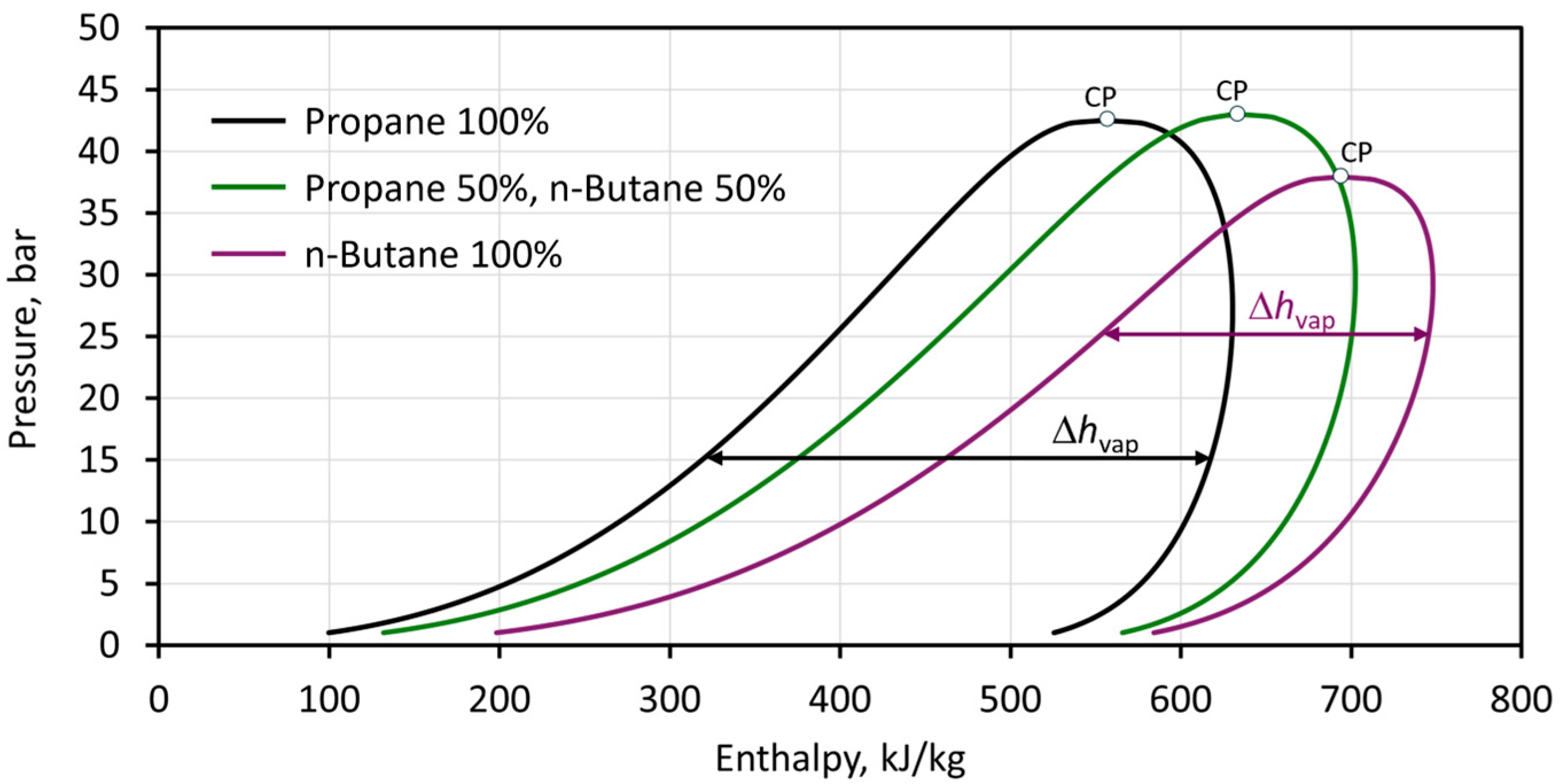
The pressure–enthalpy charts of three different LPG mixtures are shown in Figure 2. The physical properties of propane and n-butane, such as the latent heat of vaporization, the specific heat capacity, the thermal conductivity, the dynamic viscosity, and the density, are calculated using the fluid property databases REFPROP version 10.0 [21] and COOLPROP v6.7.0 [22], which are the most recent versions available as of 2025.
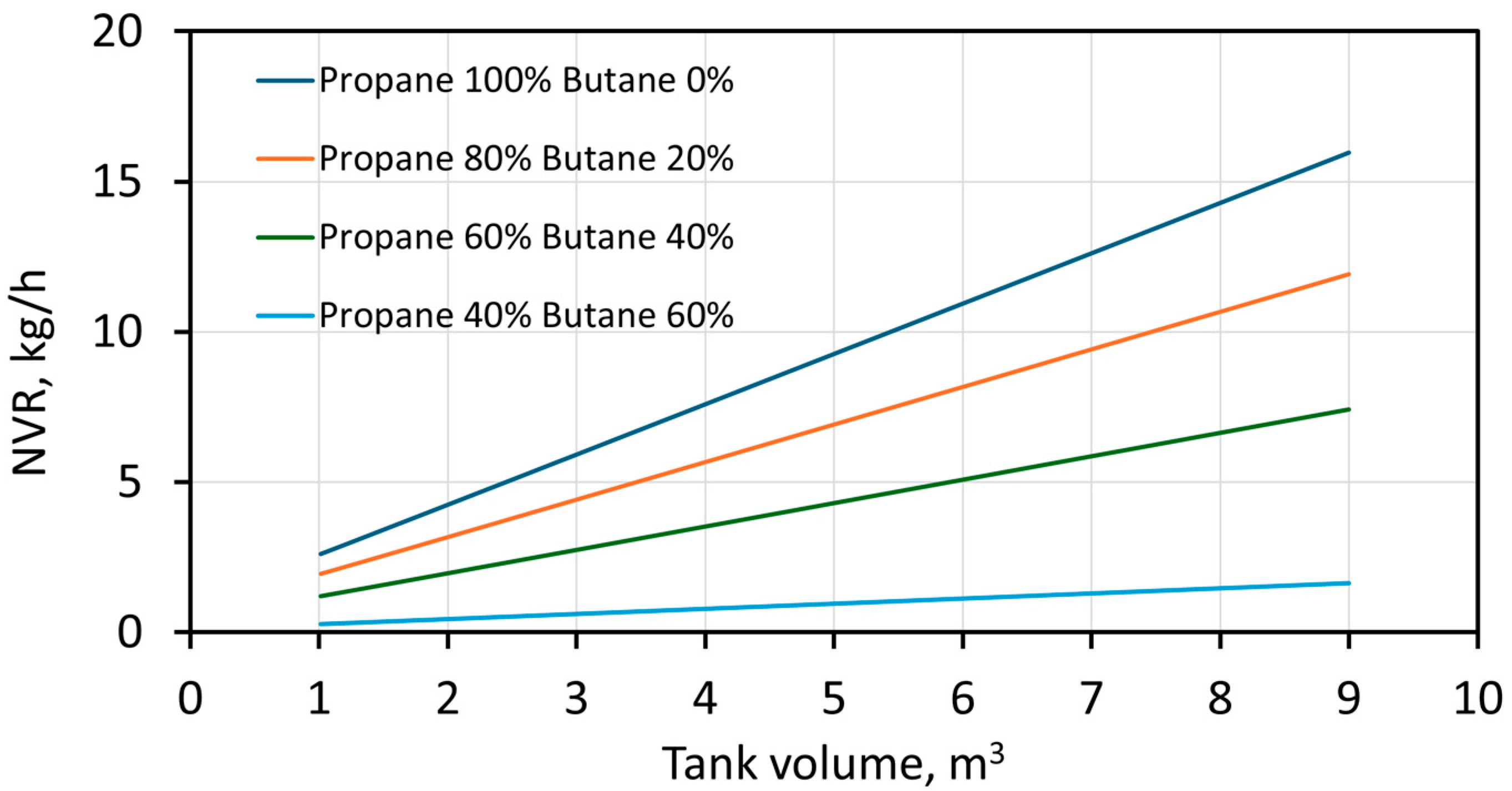
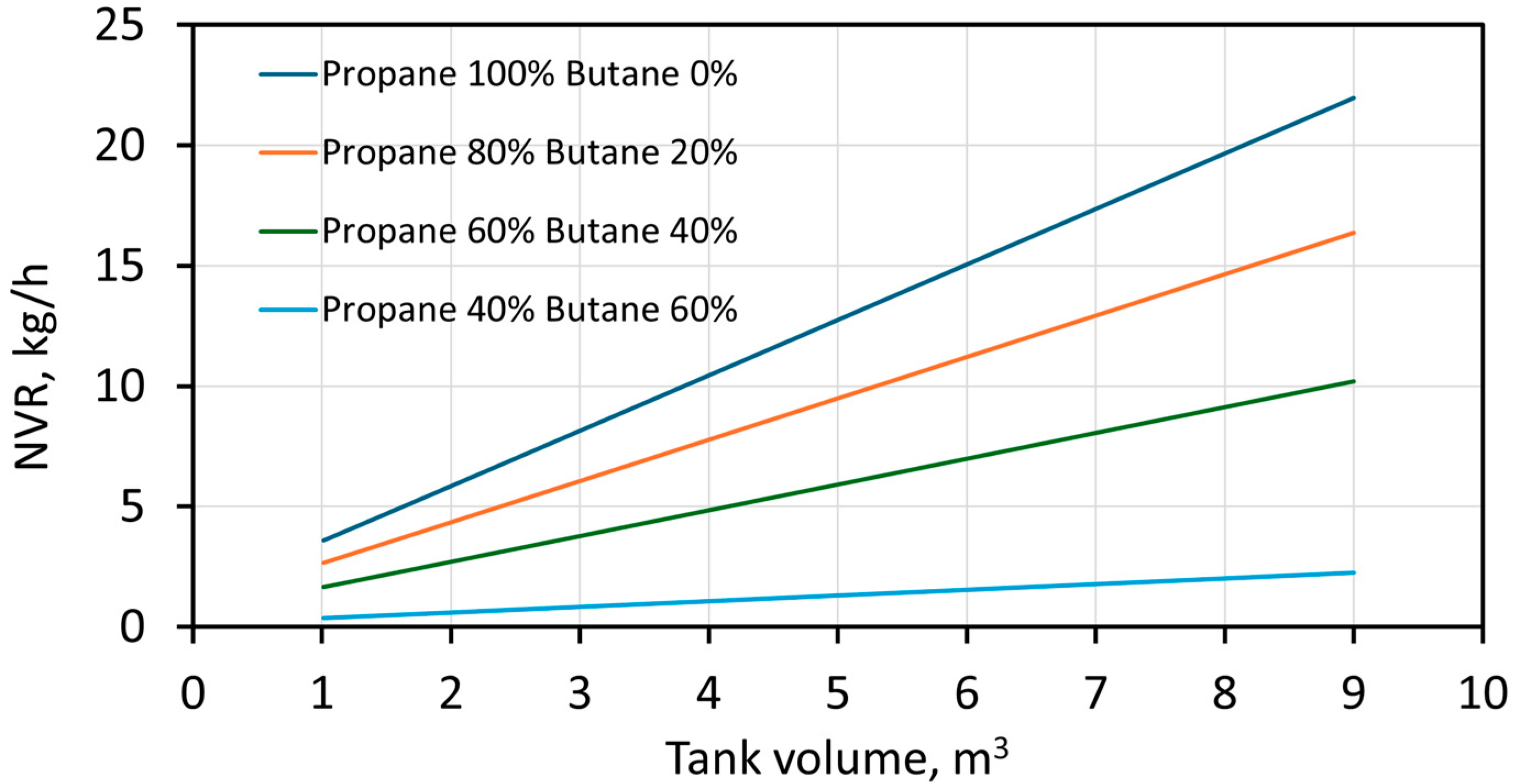
The natural vaporization rate (NVR) of aboveground horizontal LPG tanks is shown in Figure 3 and Figure 4 as a function of the tank volume and assuming the following operating conditions: tank filling fraction f = 0.2 (wetted fraction w = 0.393), external temperature Te = −8 °C, tank outer diameter Do = 1200 mm, and wall thickness t = 10 mm. The tank length, Lt, varies to accommodate the tank volume. The saturation temperature of the LPG mixture is evaluated at a mains (gauge) pressure of 0.75 bar (pabs = 1.75 bar). The overall heat transfer coefficient is, on average, 8 W/m2K for a wind velocity of 1 m/s and 11 W/m2K for a wind velocity 2 m/s, with smaller changes between tanks of different sizes.
Generally, it is seen that the NVR increases with the tank size (the wetted surface) and the propane fraction in the LPG mixture. Moreover, lower external temperatures, lower wind velocities, and higher butane fractions reduce the NVR. The impact of wind velocity is determined by an increase of 37.5% in NVR when the wind velocity doubles from 1 m/s to 2 m/s.
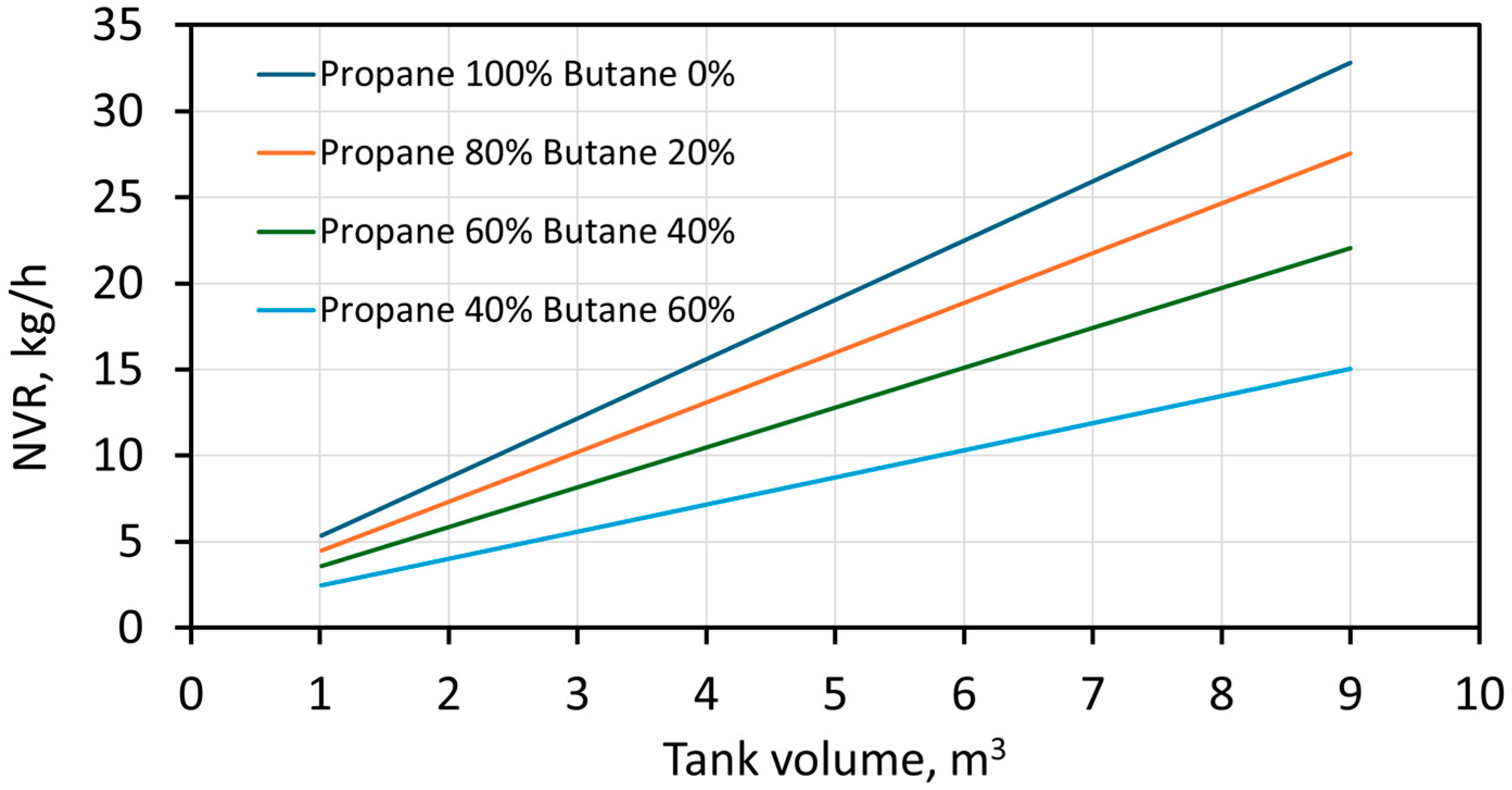
Figure 5 and Figure 6 show the NVR for a mains (gauge) pressure of 0.1 bar (pabs = 1.1 bar) and a wind velocity of 1 m/s and 2 m/s, respectively. Lower operating pressures in the tank result in lower saturation temperatures and higher natural vaporization rates.
The impact of the operating pressure is significant, especially when using butane-heavier LPG mixtures. For pure propane, the increase in the NVR is 50% when reducing the operating pressure from 1.75 bar to 1.10 bar, while for an LPG with 40% butane, the increase in the NVR is 116%.
The present results are compared against the results from the LPG tank manufacturer Lapesa [5]. The differences in natural vaporization rates reach up to 20%, and the possible causes of this discrepancy include different calculation approaches, boundary conditions, and underlying model assumptions. In the present study, the vaporization rates are calculated using a detailed analytical heat transfer model that incorporates conduction, convection (both natural and forced), and radiation while also accounting for the actual LPG tank geometry (filling fraction, wetted area) and environmental factors such as wind velocity and external temperature. The values from Lapesa [5] are derived from empirical data obtained under standardized testing conditions, which include higher ambient temperatures and steady wind conditions, which increase vaporization rates. In summary, the obtained vaporization rates in the present study are about 20% lower that those found in the literature because the present model assumes conservative operating conditions and a cold climate.

4. Conclusions

This study presented a comprehensive analysis of natural vaporization in LPG tanks, focusing on influencing factors such as the ambient temperature, tank design, LPG composition, and operating conditions. Natural vaporization rates in LPG tanks are highly sensitive to ambient temperature, wind velocity, and the propane–butane composition, with lower temperatures and higher butane content significantly reducing vaporization.
This research highlights that natural vaporization rates are often insufficient in cold climates, high-demand scenarios, and when working with butane-heavy LPG mixtures. In such cases, active vaporizers become necessary to meet the gas demand. The heat transfer analysis reveals that the heat transfer coefficient on the external wall surface is below 10 W/m2K in low-wind conditions, which can further reduce the natural vaporization rate in the LPG tank. The developed methodology provides a reliable tool for engineers to predict vaporization capacity and assess the need for supplemental vaporization systems under varying environmental and operational conditions. For an operating pressure of 1.75 bar, the specific vaporization rate per unit of tank surface area is 0.7 kg/h/m2 for an LPG with 100% propane, and this decreases to 0.4 and 0.25 kg/h/m2 for LPG mixtures with 20% and 40% butane, respectively. For a lower operating pressure of 1.10 bar, the specific vaporization rate per unit of tank surface area is 1.0 kg/h/m2 for an LPG with 100% propane, 0.85 kg/h/m2 for 20% butane, and 0.70 kg/h/m2 for 40% butane.
Further research could extend this analysis to different head geometries (spherical, dished, semi-elliptical), vertically positioned tanks, and underground LPG tanks.

Author Contributions

Conceptualization: F.P. and P.B.; methodology, P.B. and I.B.; software, F.P.; validation, P.B. and I.B.; formal analysis, F.P. and P.B.; investigation, F.P.; resources, P.B.; data curation, P.B. and I.B.; writing—original draft preparation, F.P.; writing—review and editing, P.B. and I.B.; visualization, F.P.; supervision, P.B. and I.B. All authors have read and agreed to the published version of the manuscript.

Funding

This research received no external funding.

Institutional Review Board Statement

Not applicable.

Informed Consent Statement

Not applicable.

Data Availability Statement

Data will be made available on request.

Conflicts of Interest

The authors declare no conflicts of interest.

References

  1. Green Gas: LPG Basic Principles and Practices. Available online: https://greengasjo.com/files/Gas%20Networks%20-Technical%20Overview.pdf (accessed on 10 January 2025).
  2. Morozyuk, L.; Kosoy, B.; Sokolovska-Yefymenko, V.; Ierin, V. Analysis of Mixing Processes of LPG Gases in Tanks When Transporting by Sea. Dynamics 2022, 2, 219–233. [Google Scholar] [CrossRef]
  3. Emrys Scarponi, G.; Landucci, G.; Heymes, F.; Cozzani, V. Experimental and numerical study of the behavior of LPG tanks exposed to wildland fires. Process Saf. Environ. Prot. 2018, 114, 251–270. [Google Scholar] [CrossRef]
  4. Ma, Q.; Zhong, M.; Guo, Y.; You, J.; He, Y.; Chen, J.; Zhang, Z. Study on the characteristic of boiling expansion process of superheated LPG and its vapor cloud explosion. J. Loss Prev. Process Ind. 2022, 78, 104831. [Google Scholar] [CrossRef]
  5. Lapesa: LPG Tanks with Atmospheric Vaporizer. Available online: https://www.lapesa.es/en/lpg-tanks-atmospheric-vaporizer (accessed on 10 January 2025).
  6. Lapesa: Equipment for LPG—Forced Vaporization. Available online: https://www.lapesa.es/sites/default/files/modular_equipment_vaporization_and_heating.pdf (accessed on 10 January 2025).
  7. Vasiliev, L.L.; Khrolenok, V.V.; Zhuravlyov, A.S. Intensification of heat transfer at propane pool boiling on single horizontal tubes. Rev. Gén. Therm. 1998, 37, 962–967. [Google Scholar] [CrossRef]
  8. Chiang, C.H.; Raju, M.S.; Sirignano, W.A. Numerical analysis of convecting, vaporizing fuel droplet with variable properties. Int. J. Heat Mass Transf. 1992, 35, 1307–1324. [Google Scholar] [CrossRef]
  9. Oh, S.J.; Kwon, J.; Jeon, K.S.; Yoon, J.H. A Numerical Analysis Study on the Characteristics of Evaporation in Liquid Hydrogen Tank with Vacuum Layer According to Changes in Heat Flux and Vacuum Pressure. Int. J. Hydrogen Energy 2024, 50, 542–557. [Google Scholar] [CrossRef]
  10. Ejeh, C.J.; Akhabue, G.P.; Agyeibi, I. Effect of Transient Temperature on 304 Stainless Steel LPG Tank Structure Using Numerical Simulation Approach. SN Appl. Sci. 2019, 1, 1690. [Google Scholar] [CrossRef]
  11. Lomazzi, L.; Passoni, S.; Mereu, R.; Cadini, F.; Giglio, M. In-Depth Analysis of the Burst of a Liquefied Petroleum Gas Tank in Gravedona, Italy. Energies 2024, 17, 3741. [Google Scholar] [CrossRef]
  12. Pavković, B.; Čarija, Z.; Samardžić, I. Analysis of Propane Thermal State in Underground Tanks Taking into Consideration Design Issues. Strojarstvo 2008, 50, 387–394. [Google Scholar]
  13. RedRiver: Exploring the Four Primary Head Types for Pressure Vessels. Available online: https://www.redriver.team/exploring-the-four-primary-head-types-for-pressure-vessels/ (accessed on 10 January 2025).
  14. Wolfram MathWorld: Torispherical Dome. Available online: https://mathworld.wolfram.com/TorisphericalDome.html (accessed on 10 January 2025).
  15. BS EN 12542:2020; LPG Equipment and Accessories—Static Welded Steel Cylindrical Pressure Vessels, Serially Produced for the Storage of Liquefied Petroleum Gas (LPG) Having a Volume not Greater Than 13 m3—Design and Manufacture. British Standards Institution (BSI): London, UK, 2020.
  16. BS EN 10028-2:2017; Flat Products Made of Steels for Pressure Purposes—Non-Alloy and Alloy Steels with Specified Elevated Temperature Properties. British Standards Institution (BSI): London, UK, 2017.
  17. EN 10273 Grade P265GH normalized or normalized formed (+N). Available online: https://www.shipplatesteelpro.com/EN-10273-Grade-P265GH.html (accessed on 21 April 2025).
  18. Cengel, Y.; Ghajar, A. Heat and Mass Transfer: Fundamentals and Applications, 6th ed.; McGraw Hill: New York, NY, USA, 2020. [Google Scholar]
  19. Bejan, A.; Kraus, A.D. Heat Transfer Handbook; John Wiley & Sons, Inc.: Hoboken, NJ, USA, 2003. [Google Scholar]
  20. Stephan, K.; Abdelsalam, M. Heat transfer correlations for natural convection boiling. Int. J. Heat Mass Transf. 1980, 23, 73–87. [Google Scholar] [CrossRef]
  21. Huber, M.L.; Lemmon, E.W.; Bell, I.H.; McLinden, M.O. The NIST REFPROP Database for Highly Accurate Properties of Industrially Important Fluids. Ind. Eng. Chem. Res. 2022, 61, 7858–7873. [Google Scholar] [CrossRef] [PubMed]
  22. Bell, I.H.; Wronski, J.; Quoilin, S.; Lemort, V. Pure and Pseudo-pure Fluid Thermophysical Property Evaluation and the Open-Source Thermophysical Property Library CoolProp. Ind. Eng. Chem. Res. 2014, 53, 2498–2508. [Google Scholar] [CrossRef] [PubMed]
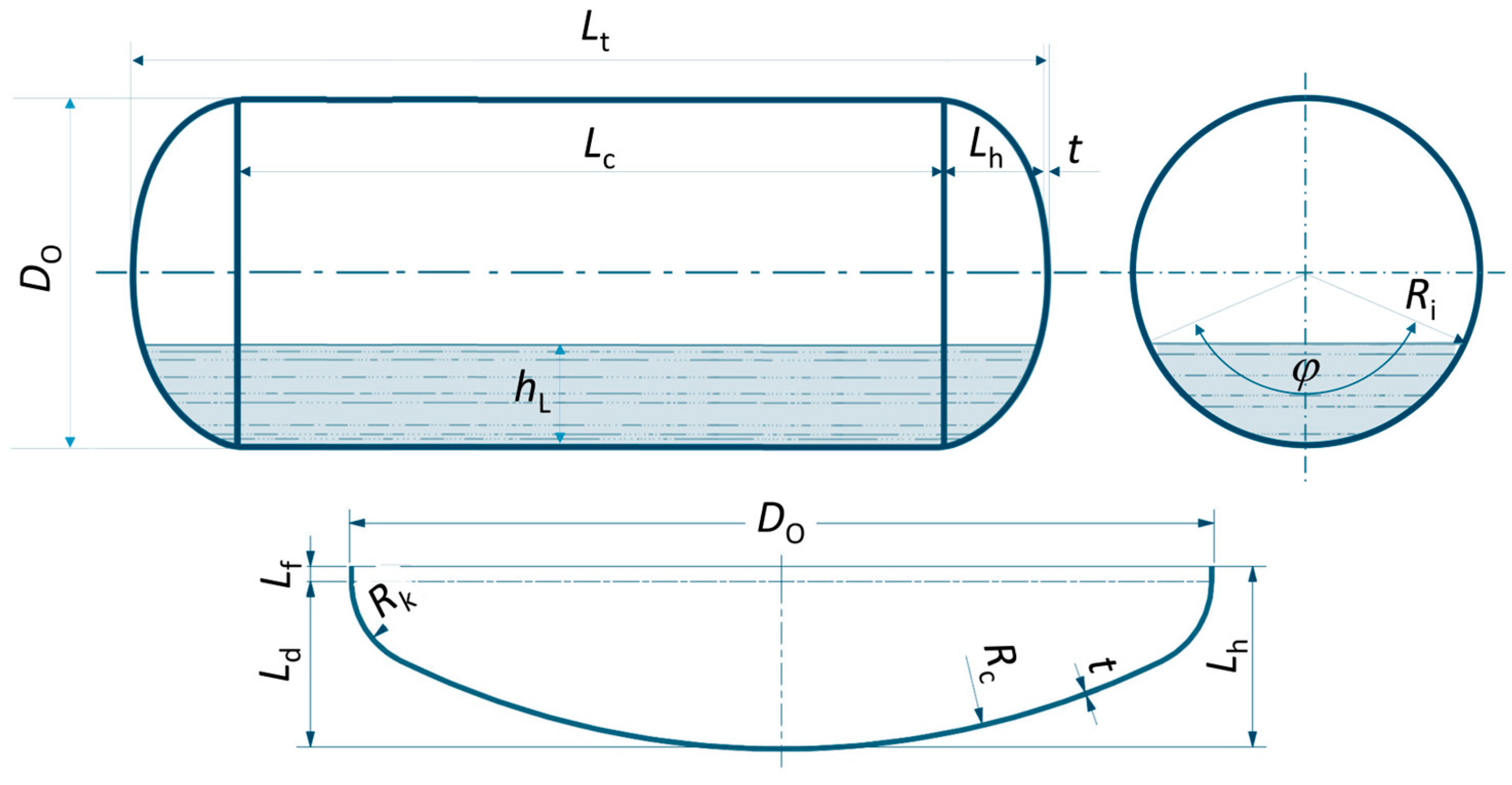
Figure 1. Principal dimensions of the LPG tank fitted with torispherical heads.
Engproc 87 00098 g001
Figure 2. Pressure–enthalpy charts for propane, n-butane, and their equal-share mixture.
Engproc 87 00098 g002
Figure 3. Natural vaporization rate (NVR) in aboveground horizontal LPG tanks for a mains pressure of 0.75 bar (pabs = 1.75 bar) and wind velocity w = 1 m/s.
Engproc 87 00098 g003
Figure 4. NVR in aboveground horizontal LPG tanks for a mains pressure of 0.75 bar (pabs = 1.75 bar) and wind velocity w = 2 m/s.
Engproc 87 00098 g004
Figure 5. NVR in aboveground horizontal LPG tanks for a mains pressure of 0.10 bar (pabs = 1.10 bar) and wind velocity w = 1 m/s.
Engproc 87 00098 g005
Figure 6. NVR in aboveground horizontal LPG tanks for a mains pressure of 0.10 bar (pabs = 1.10 bar) and wind velocity w = 2 m/s.
Engproc 87 00098 g006
Disclaimer/Publisher’s Note: The statements, opinions and data contained in all publications are solely those of the individual author(s) and contributor(s) and not of MDPI and/or the editor(s). MDPI and/or the editor(s) disclaim responsibility for any injury to people or property resulting from any ideas, methods, instructions or products referred to in the content.