1. Introduction
Hydraulic excavators are widely used in construction sites for ground leveling, digging, trenching, etc. Some of these tasks can be handed over to an autonomous excavator that is capable of doing these frequent and repetitive tasks with a high degree of accuracy. Therefore, accurate tracking of the desired trajectory is a crucial component of autonomous excavation.
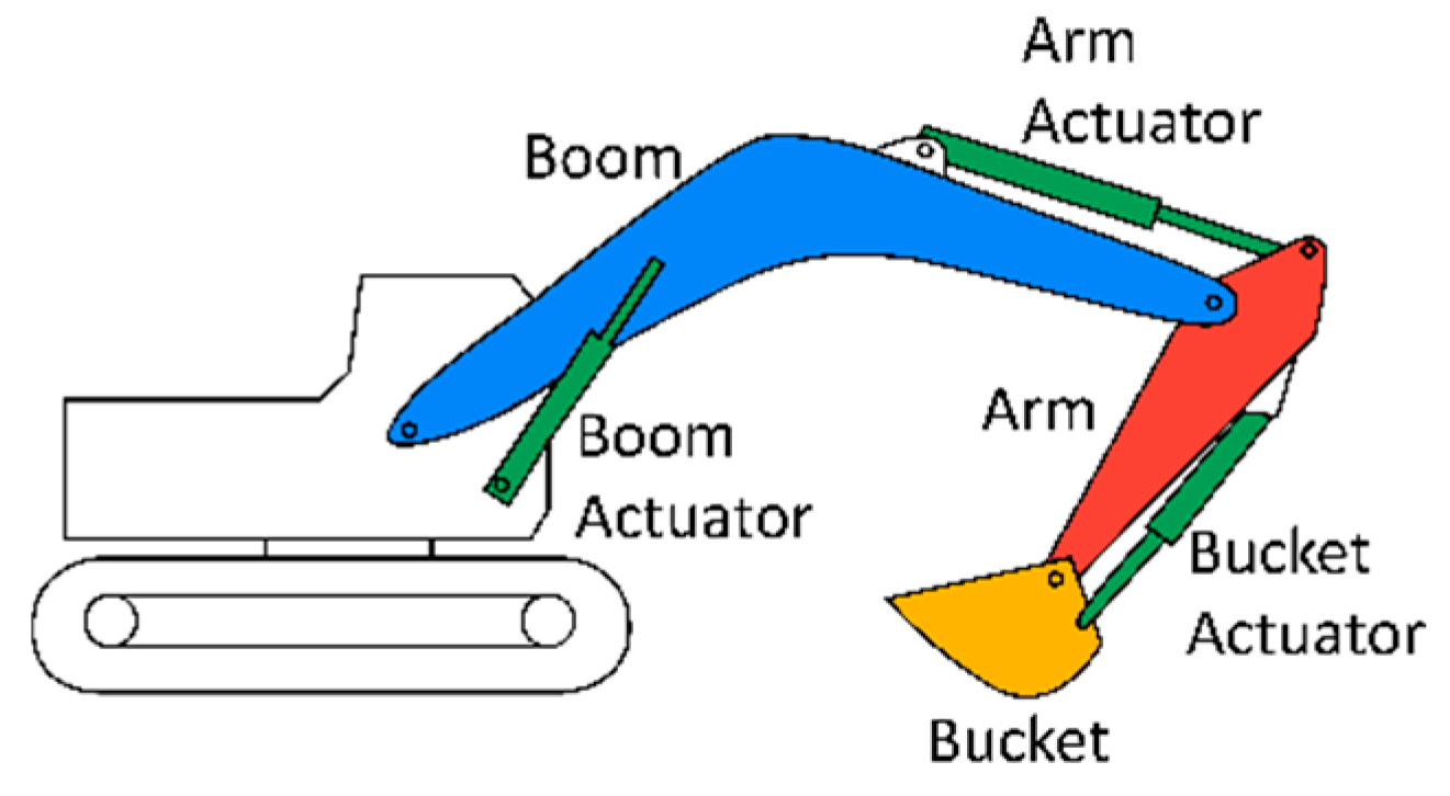
In a hydraulic excavator (
Figure 1), three main hydraulic actuators control the movement of each mechanical link by converting fluid energy into linear motion. However, uncertainties and nonlinear behaviors of these hydraulic actuators always make it challenging to design a proper control strategy for successful excavation. To solve the aforementioned problem, different control schemes have been suggested by researchers.
The author in [
1] presents an improved particle swarm optimization algorithm to tune the gains of PID controllers for the nonlinear cylinder systems for an excavator. The study in [
2,
3] applied adaptive non-linear PI control and cross-coupled precompensation. In hydraulic actuator control designs, [
4,
5] used fuzzy logic to auto-tune the PID and sliding mode parameters, respectively, while [
6] employed deep reinforcement learning. However, the previously mentioned studies except [
2,
3] mainly focused on motion control and position tracking while the studies of [
2,
3] adopting a nonlinear PID position control with cross-coupled precompensation still struggled with achieving tracking accuracy due to the uncertain dynamics of nonlinear EHAs. As a solution to this problem, our paper proposes an efficient tracking control strategy to combine fuzzy logic-based position control and contour control that can handle the uncertain and nonlinear characteristics of EHAs in excavators and minimize tracking errors for autonomous excavation. The performance of the proposed control algorithms was evaluated by a co-simulation in multi-physics domains using MATLAB Simulink and Amesim software. The remainder of the paper is organized in the following manner.
Section 2 describes the system modeling for an excavator. In
Section 3, the designed controllers are presented.
Section 4 provides an established co-simulation model. In
Section 5, validation results through a co-simulation are presented. Finally, concluding remarks are provided.
2. System Modeling
The excavator system was modeled using two sub-parts that include hydraulic and kinematic models as follows.
2.1. Hydraulic Circuit Modeling
The hydraulic actuation system in excavators behaves in a nonlinear and hysteresis manner. This feature may not be captured in simplified mathematical modeling. Therefore, EHAs were modeled using Amesim software that can employ multi-physics libraries to provide a more realistic simulation model for hydraulic applications and to couple hydraulic systems (EHAs) with mechanical components (mechanical links).
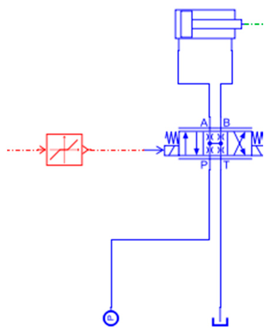
The hydraulic components considered for the modeling include a power source, 3 position/4-port hydraulic servo valves, a tank, and double-acting hydraulic cylinders.
Figure 2 illustrates an example hydraulic circuit of one cylinder modeled in Amesim software, and
Table 1 presents the parameters used for the simulation.
2.2. Kinematic Modeling
The inverse kinematics equations in Equations (1)–(3) for the bucket tip’s motion were solved analytically, which are required for the contour control design. The following Equations (1)–(3) represent the
x and
y positions and the angle of the bucket tip.
where
x and
y are the bucket tip’s position in
x and
y direction.
α is the bucket tip’s angle in workplane.
L1,
L2, and
L3 are the lengths of the arm, boom, and bucket links, respectively. Moreover,
θ1,
θ2, and
θ3 are the angles of the arm, boom, and bucket joints.
By substituting Equation (3) into Equations (1) and (2) and solving the inverse kinematics of a two-link serial manipulator with Equations (1) and (2) (i.e., only L1 and L2 links remain), the first two angles can be determined. Then, the third joint angle can be derived using Equation (3).
3. Control
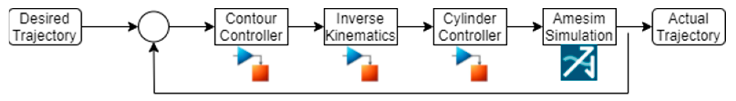
Figure 3 depicts the designed control scheme that consists of contour and cylinder controllers. The PID-based contour control was designed to compensate for the misplacement of the bucket tip on the working plane, and thus can contribute to minimizing tracking errors. The fuzzy logic cylinder control was adopted to maintain the desired stroke of each EHA by adjusting the position of servo valves. This control allows for tracking control during excavation operations due to its capability to deal with highly nonlinear and uncertain dynamics of the hydraulic components.
3.1. Contour Controller
The contour error (
ε) is defined as the shortest distance from the current actual position to the desired reference trajectory (contour) of the bucket tip that is exampled in
Figure 4. Autonomous excavation requires minimizing the contour error to achieve a desired (finished) excavation surface that goes beyond position control of the bucket tip. In the designed contour control scheme, the contour error (
ε) can be obtained using Equation (4).
where
Cx = sin(
θ)
= and
Cy = cos(
θ)
=.
Using the Jacobian matrix in Equation (5), the contour error in the Cartesian space (
ec) can be mapped with the joint space (
θe) and the contour error compensation in each axis is added to the current position in the corresponding axis to reduce the contour error along with the tracking error
).
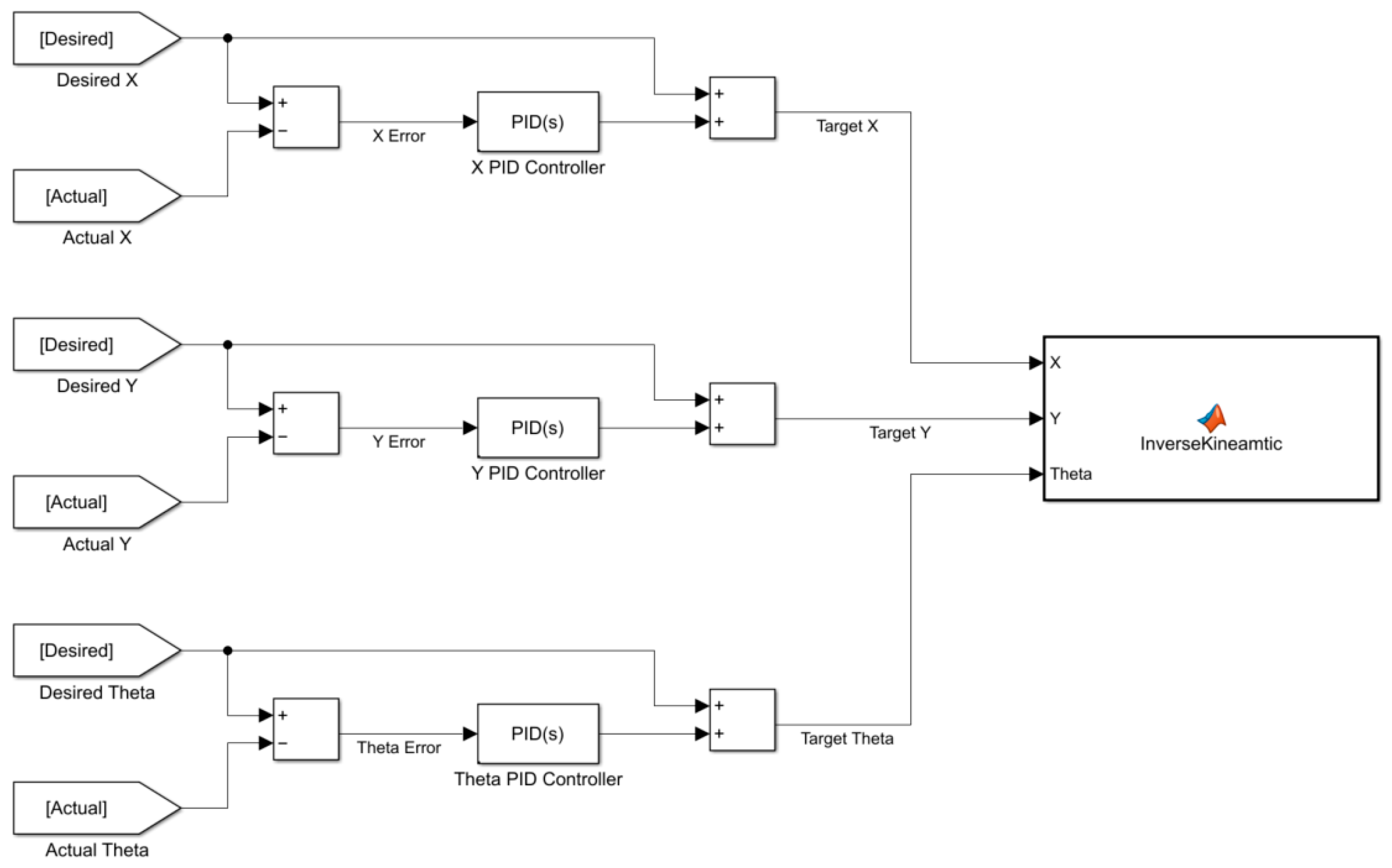
In the study, three PID controllers were added to each error of the bucket tip’s
x position,
y position, and angle. By doing so, the misplacement of the bucket tip in each axis can be independently compensated by reflecting the actual position, and thus allowing accurate contour tracking. The block diagram of the designed PID contour control is shown in
Figure 5.
3.2. Cylinder Position Control
The fuzzy logic was considered for each cylinder’s position control to handle the highly non-linearity of the EHAs. The fuzzy logic controller does not need a mathematical model of the system to achieve desired system outputs [
7], and this is effective in controlling hydraulic actuators with high nonlinearities and uncertainties.
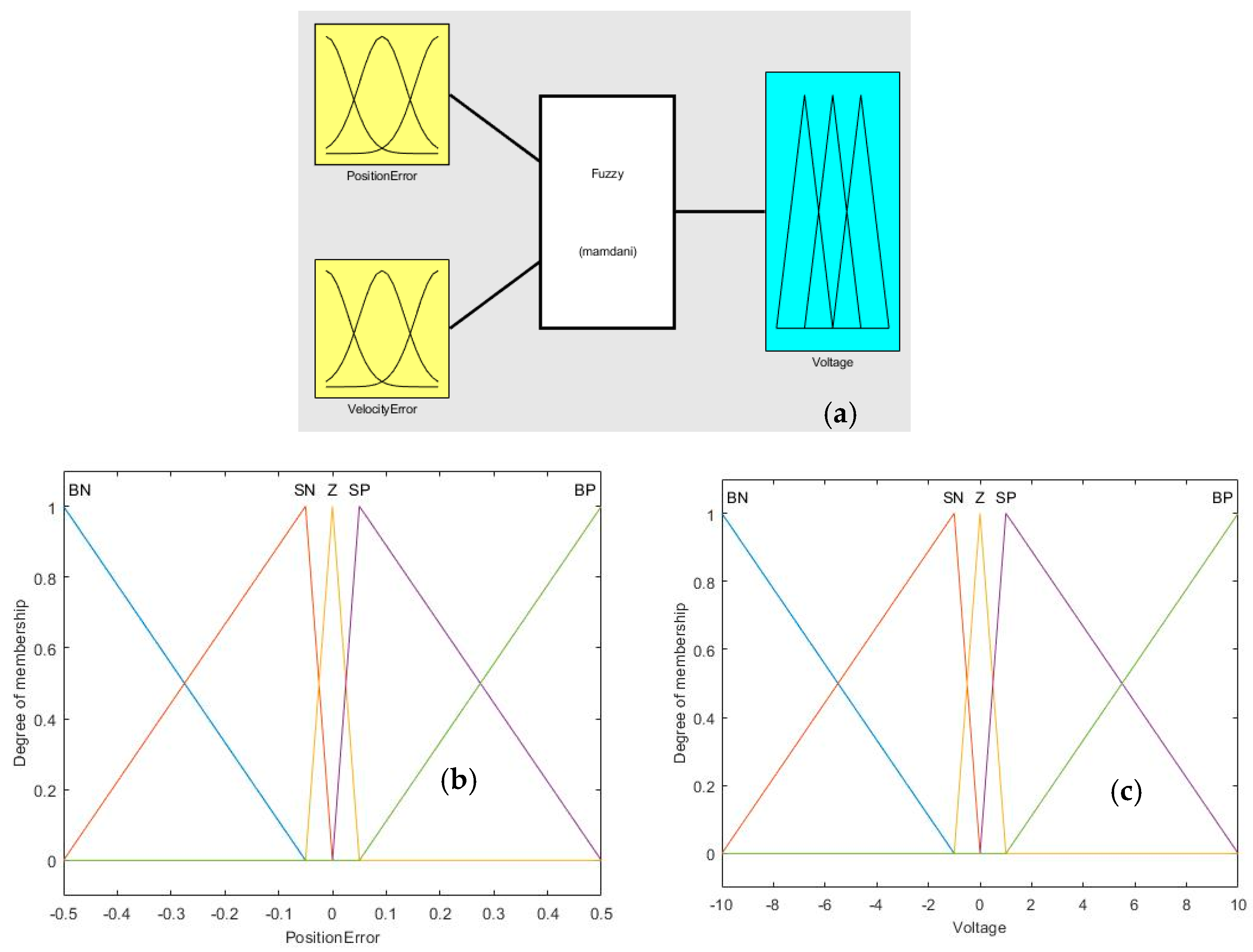
Figure 6 represents the fuzzy reference (a), and the membership functions for inputs (b) and an output (c) for the proposed fuzzy controller.
3.2.1. Inputs and Outputs
The designed controller has two inputs: position error and velocity error. The position error is defined as the signed difference between the desired position and the actual position of each hydraulic actuator. The defined velocity error is the signed difference between the desired velocity of each hydraulic actuator and its actual velocity. The control output is the voltage signal applied to the servo-valve.
3.2.2. Input and Output Fuzzifier
To fuzzify the input values, a set of membership functions need to be defined. In this paper, five sets of triangular membership functions are used as each input’s fuzzifier. The membership functions are categorized as big negative (
BN), small negative (
SN), zero (
Z), small positive (
SP), and big positive (
BP) according to the amount of error (see
Figure 6b). Just as with the input variables, the fuzzification of the output variable (voltage to the electro-valve) can be achieved with five triangular membership functions as seen in
Figure 6c).
3.2.3. Fuzzy Inference System and Defuzzification
For the fuzzy inference system, the Mamdani method was selected. We used the min method for both ‘And’ and ‘Implication’ and the max method for both ‘Or’ and ‘Aggregation’. As the output of the fuzzy inference system is a fuzzified set, it must be converted to a numerical value by defuzzification. The centroid method was chosen for the defuzzification in this study.
3.2.4. Rules
As the designed fuzzy controller contains two inputs each of which has five membership functions. Thus, a total of 25 rules must be defined.
Table 2 shows the defined rule sets.
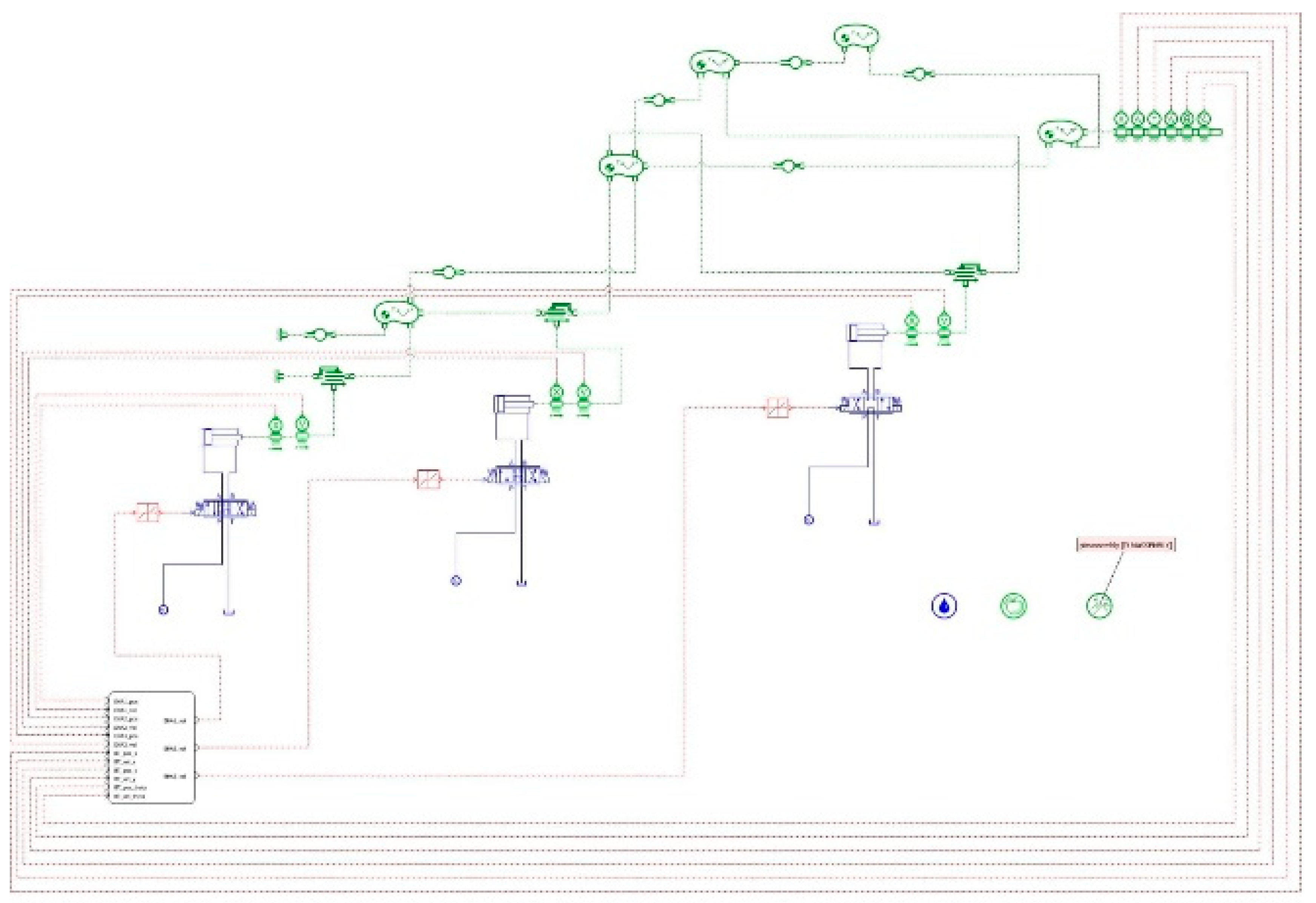
3.2.5. Co-Simulation
The hydraulic components for an excavator were modeled using Amesim software that allows modeling multi-domain physical systems such as hydraulic, mechanical, and control. Additionally, it allows the creation of more realistic simulation models, particularly for hydraulic applications with inherent nonlinearity and complex behavior. Finally, since it provides a co-simulation interface with Matlab/Simulink in which the developed control algorithms were designed. Therefore, a more accurate control validation can be achieved when compared to separate simulations for a coupled system (multi-domain physical systems), such as an excavator.
The Simulink model generates the voltage signals to drive servo valves and the Amesim model operates the hydraulic components and mechanical manipulators based on those signals. After that, the feedback from Amesim is used to send the new voltage signals.
Figure 7 represents the co-simulation model in Amesim software.
4. Results
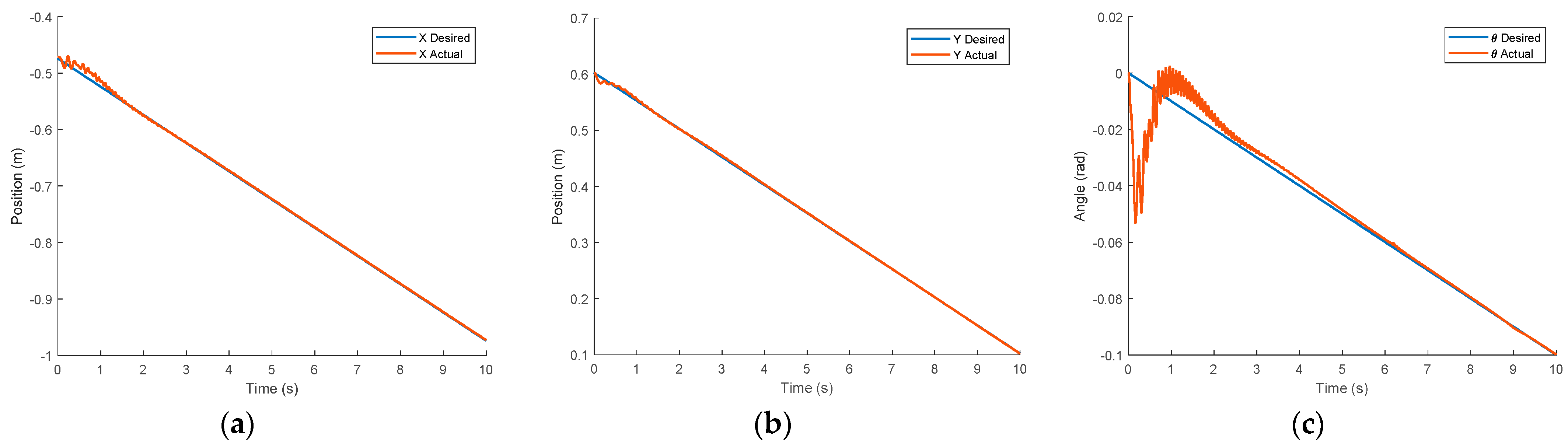
Figure 8 presents simulation results that include the desired trajectory (blue) and actual tracking response (red) in the bucket tip’s
x position,
y position, and angle.
As shown, the proposed controllers demonstrate satisfactory performance following the desired trajectory in each direction. Although initial vibrations and chattering are observed due to the initial establishment of the hydraulic actuators, they disappear and all responses become stable after 2 s.
5. Conclusions
In this study, a collaborative tracking control strategy for autonomous excavation is proposed to overcome the nonlinear behavior of hydraulic actuators and improve the tracking accuracy through contour error compensation, which has been neglected in most of the previous studies neglected. For the control design, PID and fuzzy logic approaches were integrated to deal with the contour and position controls, respectively.
To validate the performance of the developed controllers, a multi-domain simulation model was created for co-simulations, which includes the control algorithms designed in Matlab and the excavator’s mechanical and hydraulic systems modeled in Amesim. Simulation results confirm that the proposed control strategy provides high tracking accuracy by combining contour error compensation with cylinder position control. Moreover, decoupling the control algorithms into two layers of position and contour allows for independent tuning and an easier control design process, and thus enhances the tracking precision in the application of autonomous construction and agricultural actuation systems.
Author Contributions
Writing—original draft preparation, F.H.S.; Writing—original draft preparation, A.A.; writing—review and editing, J.S. All authors have read and agreed to the published version of the manuscript.
Funding
This research was funded by the Discovery Grants Program of Natural Sciences and Engineering Research Council (NSERC) of Canada.
Institutional Review Board Statement
Not applicable.
Informed Consent Statement
Not applicable.
Data Availability Statement
Not applicable.
Conflicts of Interest
The authors declare no conflict of interest.
References
- Ye, Y.; Yin, C.-B.; Gong, Y.; Zhou, J.-J. Position control of nonlinear hydraulic system using an improved PSO based PID controller. Mech. Syst. Signal Proc. 2017, 83, 241–259. [Google Scholar] [CrossRef]
- Wang, D.; Zheng, L.; Yu, H.; Zhou, W.; Shao, L. Robotic excavator motion control using a nonlinear proportional-integral controller and cross-coupled pre-compensation. Autom. Constr. 2016, 64, 1–6. [Google Scholar] [CrossRef]
- Reginald, N.; Seo, J.; Rasul, A. Tracking Control of Force, Position, and Contour for an Excavator with Co-simulation. In Proceedings of the 2020 IEEE Canadian Conference on Electrical and Computer Engineering (CCECE), London, ON, Canada, 30 August–2 September 2020; pp. 1–5. [Google Scholar]
- Seo, J.; Cha, M.; Oh, K.; Park, Y.J.; Kwon, T.J. Development of Steering Control Algorithms with Self-tuning Fuzzy PID for All-terrain Cranes. In Proceedings of the 2020 20th International Conference on Control, Automation and Systems (ICCAS), Busan, Korea, 13–16 October 2020; pp. 727–730. [Google Scholar]
- Choi, J. Development of Time Varying Sliding Mode Controller with Fuzzy System for Automatic Excavator. In Proceedings of the 28th International Symposium on Automation and Robotics in Construction (ISARC 2011), Seoul, Korea, 29 June 2011; pp. 1267–1272. [Google Scholar]
- Wyrwał, D.; Lindner, T.; Nowak, P.; Białek, M. Control strategy of hydraulic cylinder based on Deep Reinforcement Learning. In Proceedings of the 2020 International Conference Mechatronic Systems and Materials (MSM), Bialystok, Poland, 1–3 July 2020; pp. 1–5. [Google Scholar]
- Gouda, M.M.; Danaher, S.; Underwood, C.P. Fuzzy Logic Control Versus Conventional PID Control for Controlling Indoor Temperature of a Building Space. IFAC Proc. Vol. 2000, 33, 249–254. [Google Scholar] [CrossRef]
| Publisher’s Note: MDPI stays neutral with regard to jurisdictional claims in published maps and institutional affiliations. |
© 2021 by the authors. Licensee MDPI, Basel, Switzerland. This article is an open access article distributed under the terms and conditions of the Creative Commons Attribution (CC BY) license (https://creativecommons.org/licenses/by/4.0/).


