Abstract
The heat extraction from and cooling of computer microprocessors are challenging tasks in the modern era. Previously, the microprocessors were usually cooled by air, but now industry is shifting towards using nanofluids, as their properties are more thermo-physically stable. The experimental and numerical studies have revealed that the rate of heat transfer depends both on the thermal characteristics of the coolant and the geometry of the heat sink. For optimized results, it is recommended to analyze the combined effect of nanofluids and the geometry of the heat sink. Mini-channel heat sinks in combination with a nanofluid offered an excellent rate of heat transfer. However, passing nanofluids continuously through the system causes various problems over time; for example, the thermal stresses on the components are increased, which may lead to wear and tear of the system. In this study, a numerical investigation of mini-channel heat sinks was conducted through thermal-FSI. A numerical model was established with airfoil and Savonius pin-fin mini channel heat sinks, and they were analyzed at different flow rates from 0.25 LPM to 0.75 LPM with an increment of 0.25 LPM with different fluids, i.e., water, Al2O3–H2O, and Fe2O3–H2O nanofluids, varying their volumetric concentration. The minimum stresses were obtained while increasing the temperature drop and decreasing the pressure drop. The thermal stresses were calculated using the thermal-FSI technique and were found to be in the threshold range, and hence the material was within the yield limit at 0.75 LPM when using the Fe2O3-H2O Nanofluid at a 0° angle using the Savonius heat sink.
1. Introduction
These days, the improvement of heat transfer in mini channel heat sinks is a very important technique for the thermal management of microelectronics systems. In the past, many researchers worked on the geometric parameters and their optimization to increase the heat transfer rate [1,2,3,4]. Fluids with heat transfer capability show a significantly high thermal conductivity when they are mixed with certain conductive nanoparticles at certain volumetric concentrations. High-performance cooling is the essential requirement of all industries in the current century. The poor thermal conductivity of conventional fluids such as water, ethylene glycol (EG), and engine oil is the primary limitation to promoting the most effective and novel type of heat transfer fluid. The thermo-physical properties of nanofluids are the main scope of the study when dealing with heat transfer applications. In the current study, minimum thermal stresses, and optimum flow rate in the heat sink were determined for the thermal management of a computer microprocessor. For this numerical investigation of the flow maldistribution in various types of heat sinks, the commercially available CFD code ANSYS CFX® was used and the results were compared with the available analytical or empirical correlations in the literature.
2. Methodology
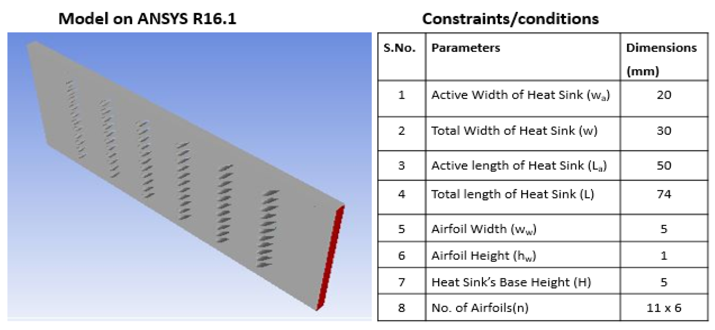
Various heat sinks with different configurations were designed and analyzed numerically to find the best heat sink, i.e., the one that gives the maximum temperature dropout and minimum stress distribution. The two main heat sinks considered for the detailed analysis were an airfoil heat sink and a Savonius heat sink. Their model details are given in Figure 1 and Figure 2. Moreover, the details of all the investigated cases for these two heat sinks have been summarized in Table 1.

Figure 1.
3D model of airfoil heat sink using ANSYS along with used conditions.
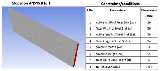
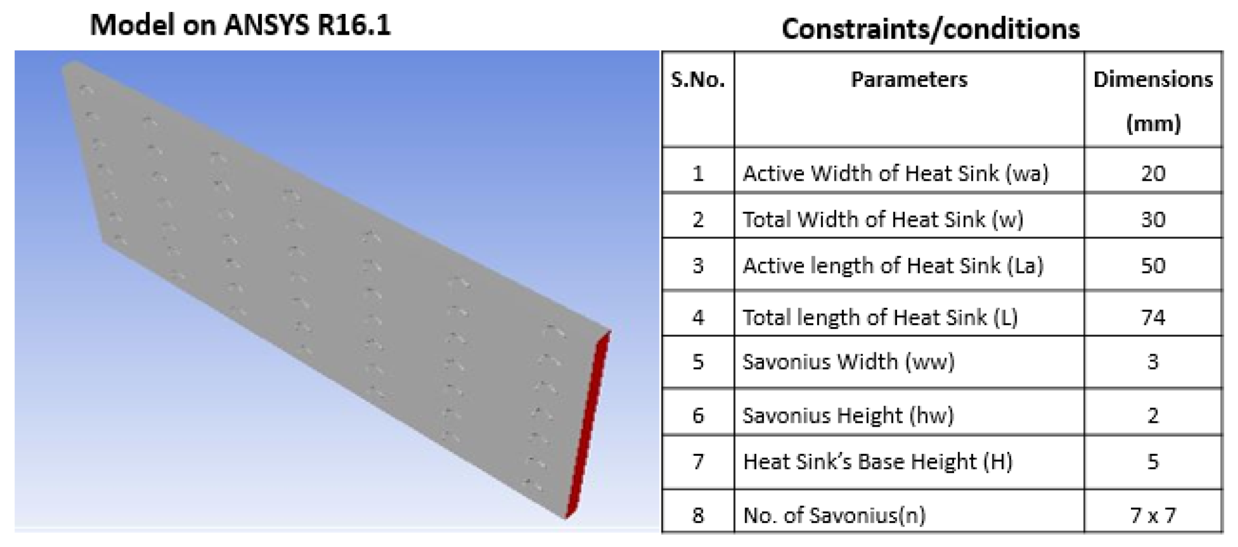
Figure 2.
3D model of Savonius heat sink using ANSYS along with used conditions.

Table 1.
Summary of all the studied cases for both heat sinks (airfoil heat sink and Savonius heat sink).
The computational model geometry and the grid were generated using ANSYS CFX 16.1®. Steady-state, mass, energy, and laminar flow equations were discretized and solved. The situation of the stable wall temperature was considered.
The nanofluids used in this study were H2O (water) as the base, with a density of 998.2 (Kg/m3) and a specific heat of 4182 (J/Kg·K); Al2O3–EG (aluminum oxide–ethylene glycol) with a density of 1105 (Kg/m3) and a specific heat of 3088 (J/Kg·K); and Fe2O3–H2O (iron oxide–water) with a density of 1010 (Kg/m3) and a specific heat of 4141 (J/Kg·K).
3. Results and Discussion
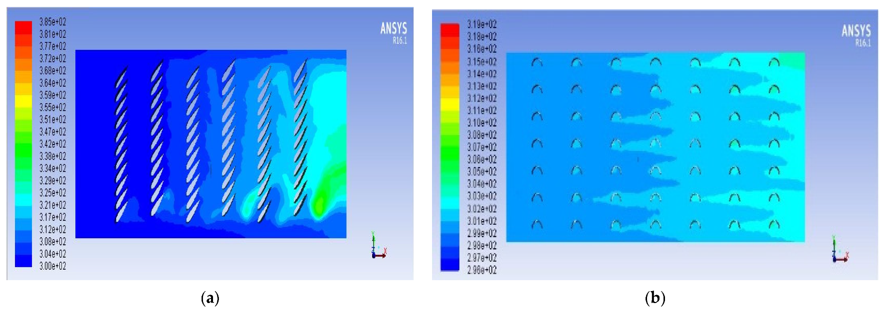
The simulated results of the airfoil heat sinks and Savonius heat sinks contain the results of a total of 27 values of 9 cases to find the maximum temperature drop with regard to the pressure at various flow rates. For each case of the airfoil heat sinks, the simulation was conducted on three different flowrates, i.e., 0.25 LPM, 0.5 LPM, and 0.75 LPM, in order to find the optimum flow rate at which the maximum heat is extracted from the system at the lowest thermal stresses. So, for each case of airfoil, there were three more cases, named as case 1-1 at 0.25 LPM, case 1-2 at 0.5 LPM, and case 1-3 at 0.75 LPM. Then, there were case 2-1 (0.75 LPM), case 2-2 (0.75 LPM), and case 2-3 (0.75 LPM), and lastly, case 3-1, case 3-2, and case 3-3 for three different flowrates in the same manner as cases 1 and 2. The same trend was repeated for the Savonius heat sink. Figure 3a shows the temperature contour of the minimum temperature drop for case 3-1 of the air foil heat sink when using the conditions of the Al2O3–EG nanofluid, while the maximum temperature drop for the Savonius heat sink in case 1-3 using the Fe2O3–H2O nanofluid is shown in Figure 3b. There is a need for the maximum temperature drop for the enhancement of heat transfer in the mini channel heat sinks, but the pressure drop should be minimum at given conditions. To overcome this, the flow rate and geometry of the heat sink should also be changed by maintaining the boundary conditions to get the desired result.
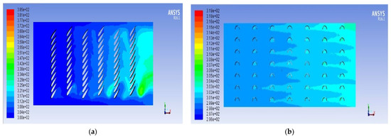
Figure 3.
Temperature contour of (a) minimum temperature drop case 3-1 of airfoil heat sink with Al2O3–EG nanofluid (b) and for maximum temperature drop in cases 1–3 of Savonius heat sink with Fe2O3-H2O nanofluid.
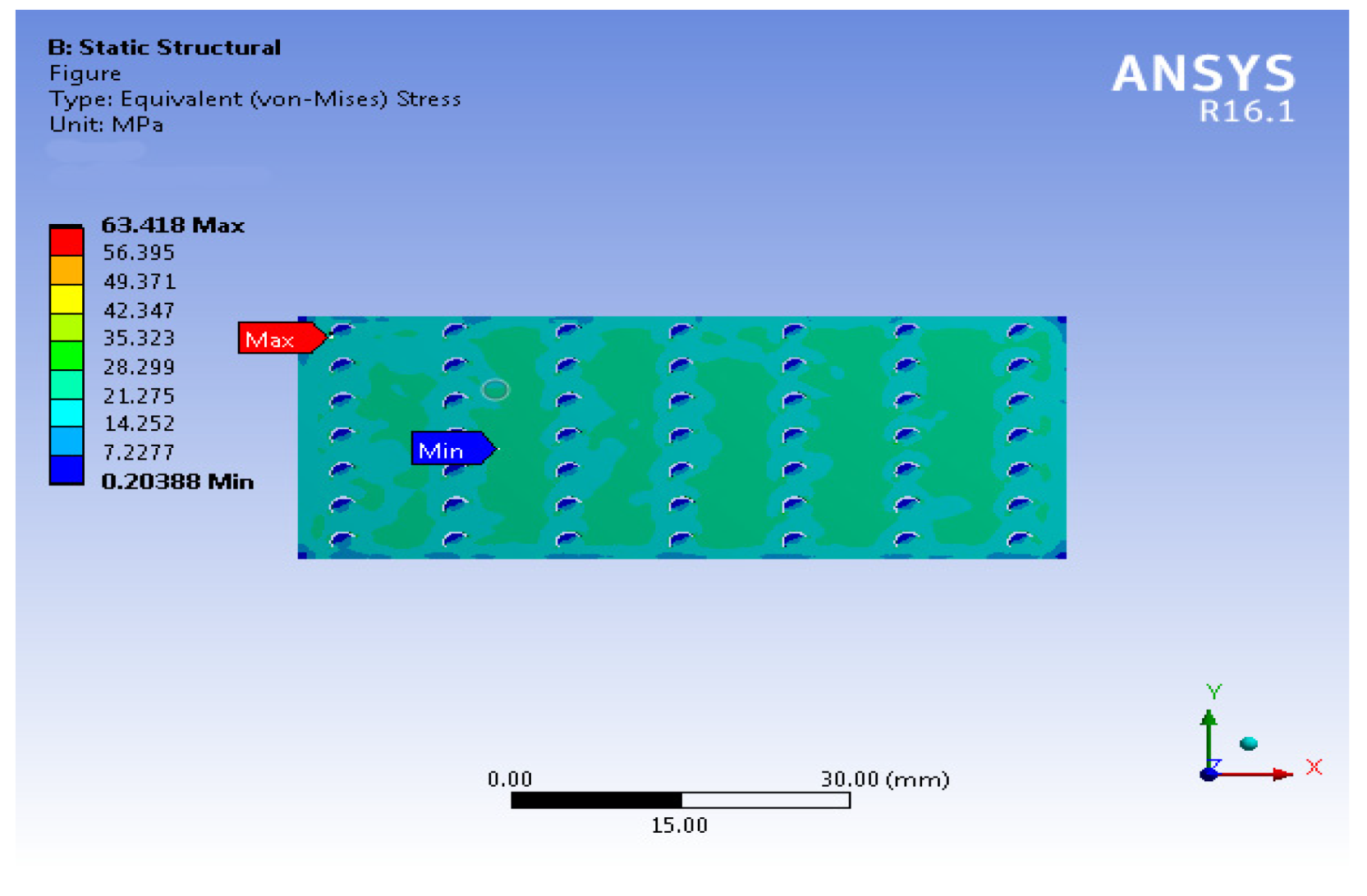
This analysis led to finding the optimum flow rate for the thermal performance parameters with structural parameters, i.e., the generated stresses were studied together by applying thermal and pressure loads on the structural part of the heat sink. Airfoil and Savonius pin-fin mini channel heat sinks were analyzed at different flow rates by varying them from 0.25 LPM to 0.75 LPM with an increment of 0.25 LPM with different fluids, i.e., water, Al2O3–H2O, and Fe2O3–H2O nanofluids, by varying the volumetric concentration. The minimum stresses were obtained while increasing the temperature drop and decreasing pressure drop as shown in Figure 4. Regardless of the positive aspects of nanofluids, the problem of the agglomeration of particles has not yet been resolved. Much better results could be obtained by investigating the position and orientation of the fins. By using various combinations of hybrid nanofluids, more heat can be extracted from the system, keeping thermal stresses to a minimum.
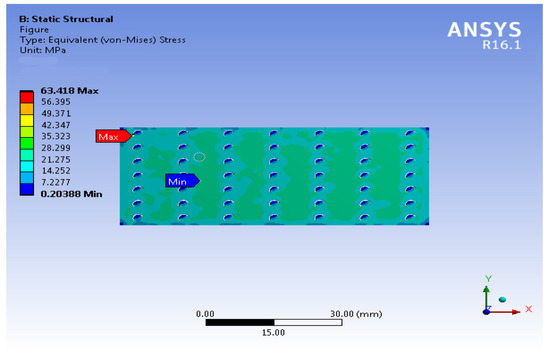
Figure 4.
Contour of channel stresses using Fe2O3–H2O nanofluid.
4. Conclusions
It is concluded from the numerical investigation that the Fe2O3–H2O nanofluid showed the highest heat transfer rates compared to Al2O3–EG and distilled water during its use on various heat sinks. The minimum temperature value was received from the simulation of the Fe2O3–H2O nanofluid, and it showed that the thermal stresses are also within the yield strength limits of the material. It is noticed that the thermal conductivity increases only with the mass fraction of nanoparticles. Although it is known that thermal conductivity is the function of temperature, it has no effect on the enhancement of thermal conductivity.
Acknowledgments
The authors acknowledge the support of the Department of Energy Systems Engineering, UAF for providing the computational facility developed under the HEC funded project TDF-061.
Conflicts of Interest
The corresponding author declares, on behalf of all the authors, that this submission has no conflicts of interest of any type.
References
- Madhesh, D.; Parameshwaran, R.; Kalaiselvam, S. Experimental investigation on convective heat transfer and rheological characteristics of Cu–TiO2 hybrid nanofluids. Exp. Therm. Fluid Sci. 2014, 52, 104–115. [Google Scholar] [CrossRef]
- Kong, L.; Sun, J.; Bao, Y. Preparation, characterization and tribological mechanism of nanofluids. Rsc. Adv. 2017, 7, 12599–12609. [Google Scholar] [CrossRef] [Green Version]
- Sundar, L.S.; Singh, M.K.; Sousa, A.C. Enhanced heat transfer and friction factor of MWCNT–Fe3O4/water hybrid nanofluids. Int. Commun. Heat Mass Transf. 2014, 52, 73–83. [Google Scholar] [CrossRef]
- Saeed, M.; Kim, M.-H. Header design approaches for mini-channel heatsinks using analytical and numerical methods. Appl. Therm. Eng. 2017, 110, 1500–1510. [Google Scholar] [CrossRef]
Publisher’s Note: MDPI stays neutral with regard to jurisdictional claims in published maps and institutional affiliations. |
© 2021 by the authors. Licensee MDPI, Basel, Switzerland. This article is an open access article distributed under the terms and conditions of the Creative Commons Attribution (CC BY) license (https://creativecommons.org/licenses/by/4.0/).