Article

Qualification and Pre-Screening of Lubricants for Use in High-Pressure Hydrogen Tanks: Ensuring ISO 14687 Grade D Purity Within Fuel Cell Drive Trains


1
HyCentA Research GmbH, A-8010 Graz, Austria
2
DuPont Specialty Products GmbH & Co. KG, 65201 Wiesbaden, Germany
3
Institute of Thermodynamics and Sustainable Propulsion Systems, Graz University of Technology, A-8010 Graz, Austria
*
Author to whom correspondence should be addressed.
Hydrogen 2026, 7(2), 83; https://doi.org/10.3390/hydrogen7020083
Submission received: 3 April 2026 / Revised: 29 May 2026 / Accepted: 3 June 2026 / Published: 16 June 2026

Abstract

Fuel cell electric vehicles (FCEVs) require specific hydrogen purity, as even trace contaminants can degrade proton exchange membrane fuel cells (PEMFCs). While hydrogen quality is monitored along the supply chain according to international standards, potential contamination from in-vehicle materials, such as lubricants and greases, remains largely unexplored. Here, we present a staged testing framework consisting of (i) a rapid pre-screening for formulation stability and (ii) a full qualification pathway to assess lubricant-derived contamination under realistic refueling conditions. Candidate lubricants were exposed to hydrogen in a 700 bar Type IV vessel following an SAE J2601 refueling procedure. Contamination risks were evaluated by optical inspection, particulate matter, and gas analysis, monitoring contaminants specified in ISO 14687:2025 Grade D. The applicability of the framework was demonstrated in practical scenarios. In the pre-screening pathway, a silicone-based formulation fulfilled the 24 h acceptance criteria for formulation stability and was classified as potentially suitable for high-pressure hydrogen tank applications. In contrast, two other lubricants based on silicone and mineral oil exhibited visible changes associated with increased risk of particulate matter release, resulting in a classification of unsuitable. In the full qualification pathway, the fluorinated DuPontTM MOLYKOTE® HP-300 Grease was evaluated over 23 days and showed no release of harmful contaminants into the hydrogen gas, leading to the classification of suitable. Collectively, the presented protocols provide a structured basis for screening and qualifying lubricants for high-pressure hydrogen tanks in PEMFC applications, supporting future standardization in hydrogen technologies.

1. Introduction

Hydrogen quality is a critical parameter influencing the performance and adoption of emerging hydrogen technologies. Purity requirements are defined in international standards, such as ISO 14687:2025 [1], ISO 21087:2019 [2], ISO 19880-8:2024 [3], and SAE J2719_202003 [4], which specify allowable concentration limits for individual contaminants across various use cases. Embedded in technical guidelines and regulatory frameworks, this standard plays a pivotal role in ensuring reliability and compatibility across the growing hydrogen infrastructure [5,6,7,8,9].
A prime example of its importance is found in proton exchange membrane fuel cells (PEMFCs), a cornerstone technology for decarbonizing both transportation and stationary power sectors due to their high efficiency, rapid start-up, and compatibility with renewable hydrogen [10,11,12,13]. The long-term performance and durability of PEMFCs are highly sensitive to hydrogen purity, with even trace levels of certain contaminants capable of reducing stack lifetime and efficiency. The effects of hydrogen contaminants on PEMFC components are summarized in international norms, such as EN 17124:2025 [14] and several review papers [15,16,17]. For instance, carbon monoxide (CO), ammonia (NH3), and hydrogen sulfide (H2S) have been reported to cause irreversible catalyst poisoning, membrane degradation, or blockage of active sites at the electrodes [15,17,18,19,20]. To safeguard PEMFC operation against such degradation mechanisms, ISO 14687:2025 [1] Grade D prescribes strict hydrogen quality requirements, which are enforced through routine monitoring within the hydrogen supply chain, encompassing production, purification, compression, and distribution stages up to the point of dispensing [21,22,23,24,25,26,27].
However, despite upstream control, onboard contamination of fuel cell electric vehicles (FCEVs) remains largely unaddressed in current quality assurance protocols. Previous studies have shown that materials used in fuel cell systems, including lubricants, adhesives, sealants, hoses, and structural materials, can release contaminants that affect PEMFC performance and durability [28]. In particular, lubricants, including grease-type formulations—hereafter referred to collectively as lubricants to describe materials commonly applied to seal valves, fittings, and on-tank valves (OTVs)—have been identified by the U.S. National Laboratory of the Rockies (NRL) as potential contamination sources through in situ FC testing [28]. Additionally, lubricating oils, specifically in the presence of water traces, have been reported to facilitate the interaction of hydrogen and metallic tank components, causing increased hydrogen permeation and potential material degradation under thermal stress [29,30,31,32,33,34,35]. These findings indicate that lubricants not only threaten the structural integrity of hydrogen storage systems but also affect fuel cell integrity and pose a risk to maintaining ISO 14687:2025 Grade D compliance in the fuel cell drive train.
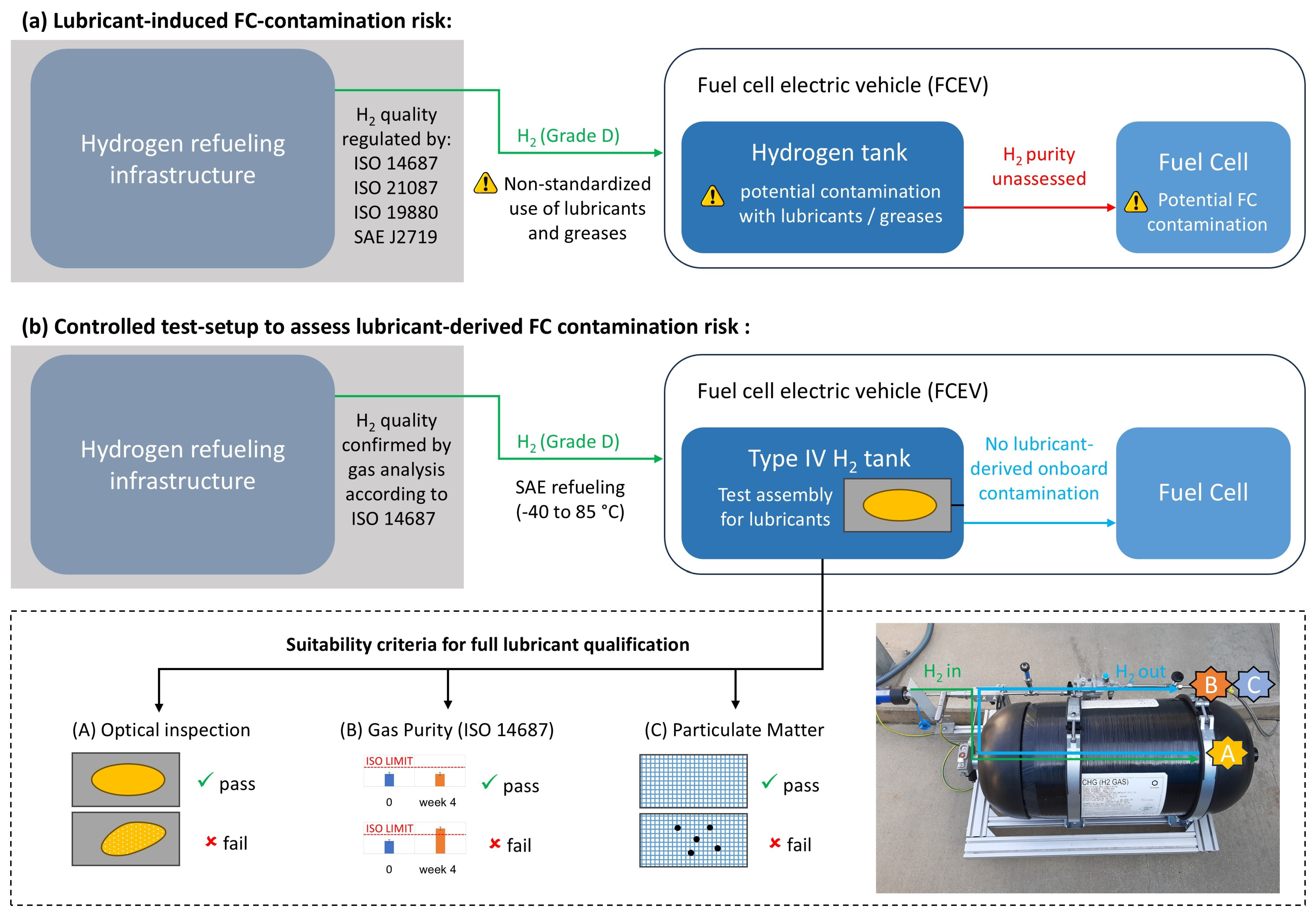
Against this background, lubricant-induced contamination during refueling represents a specific but rarely addressed pathway by which hydrogen may fail to meet PEMFC purity requirements. In FCEVs, lubricants are typically applied to OTVs and directly exposed to hydrogen at pressures up to 700 bar and temperatures ranging from −40 °C to +85 °C [36]. Under these conditions, lubricants may degrade and contaminate the tank, releasing volatile organic compounds or particulate matter into the hydrogen gas. Such impurities can subsequently enter the fuel cell system undetected, potentially causing damage to the PEMFC stack over time (Figure 1a). While ISO 14687:2025 acknowledges this hazard by requiring refueling stations to prevent contamination from operating fluids [1], standardized and methodologically simple methods for evaluating lubricant suitability for high-pressure hydrogen tanks in FCEVs are currently not available.
In this work, we introduce a staged framework for the assessment of lubricants intended for use in FCEV hydrogen tanks, particularly during refueling. The framework consists of a simplified pre-screening protocol for rapid compatibility assessment and a full qualification pathway for application-relevant testing under realistic hydrogen exposure conditions. Both protocols are based on defined lubricant suitability criteria, including visual inspection and compliance with ISO 14687:2025 Grade D hydrogen purity requirements, and are designed to evaluate hydrogen contamination originating from onboard lubricant sources in Type IV hydrogen tanks (Figure 1b). In both stages, candidate lubricants are applied to stainless steel sinter plates and exposed to hydrogen under SAE J2601 automotive refueling conditions [36]. The pre-screening protocol enables rapid evaluation and early elimination of potentially unstable lubricant formulations within 24 h, whereas in the full qualification pathway, lubricant suitability is assessed over a 23-day dwell period in the hydrogen tank. The applicability of the framework is demonstrated in practical test scenarios, in which finished lubricant formulations with only partially disclosed compositional information were evaluated against the pre-defined acceptance and protocol completion criteria, resulting in classification of the tested lubricants as suitable, potentially suitable, or unsuitable for use in FCEV hydrogen tanks.
Combined, this testing framework provides a structured methodology for ensuring compliance with ISO 14687:2025 Grade D hydrogen quality requirements and supporting the protection of PEM fuel cell performance and durability.

2. Experimental Test Setup

To evaluate the risk of lubricant-induced hydrogen contamination under realistic refueling conditions, a dedicated testing protocol was developed. The test setup employed a commercially available 70 L Type IV hydrogen tank (76 L, Hexagon Purus ASA, Oslo, Norway, maximum allowable filling pressure of 875 bar) equipped with hydrogen-compatible instrumentation for pressure regulation, gas sampling, and in-line purity monitoring. Type IV tanks are characterized by a thermoplastic PA/PE liner and a full carbon- or glass-fiber composite overwrap, providing weight advantages compared with metallic tank concepts that make them the preferred onboard storage technology for mobile PEMFC applications, including passenger cars, buses, and trucks operating at 350 or 700 bar [37]. Since PEM fuel cells are the most common fuel cell type for vehicle applications, the selected Type IV tank represents the relevant storage technology for the investigated PEMFC-based FCEV use case [38].
Analytic instruments included a Shimadzu AP125WD precision scale (Shimadzu Handelsgesellschaft mbH, Korneuburg, Austria), a Matrix MG 5 real-time Fourier transform infrared (FTIR) gas analyzer (Bruker Austria Gmbh, Vienna, Austria), a combined ion–molecule reaction (IMR) and electron impact (EI) mass spectrometer (ComboSense®, V&F Analyse- und Messtechnik GmbH, Absam, Austria), and a Zeiss Stemi 305 optical microscope (Carl Zeiss GmbH, Vienna, Austria). Detailed descriptions and analytic procedures are provided in Section 3.

2.1. Preparation of Test Assemblies

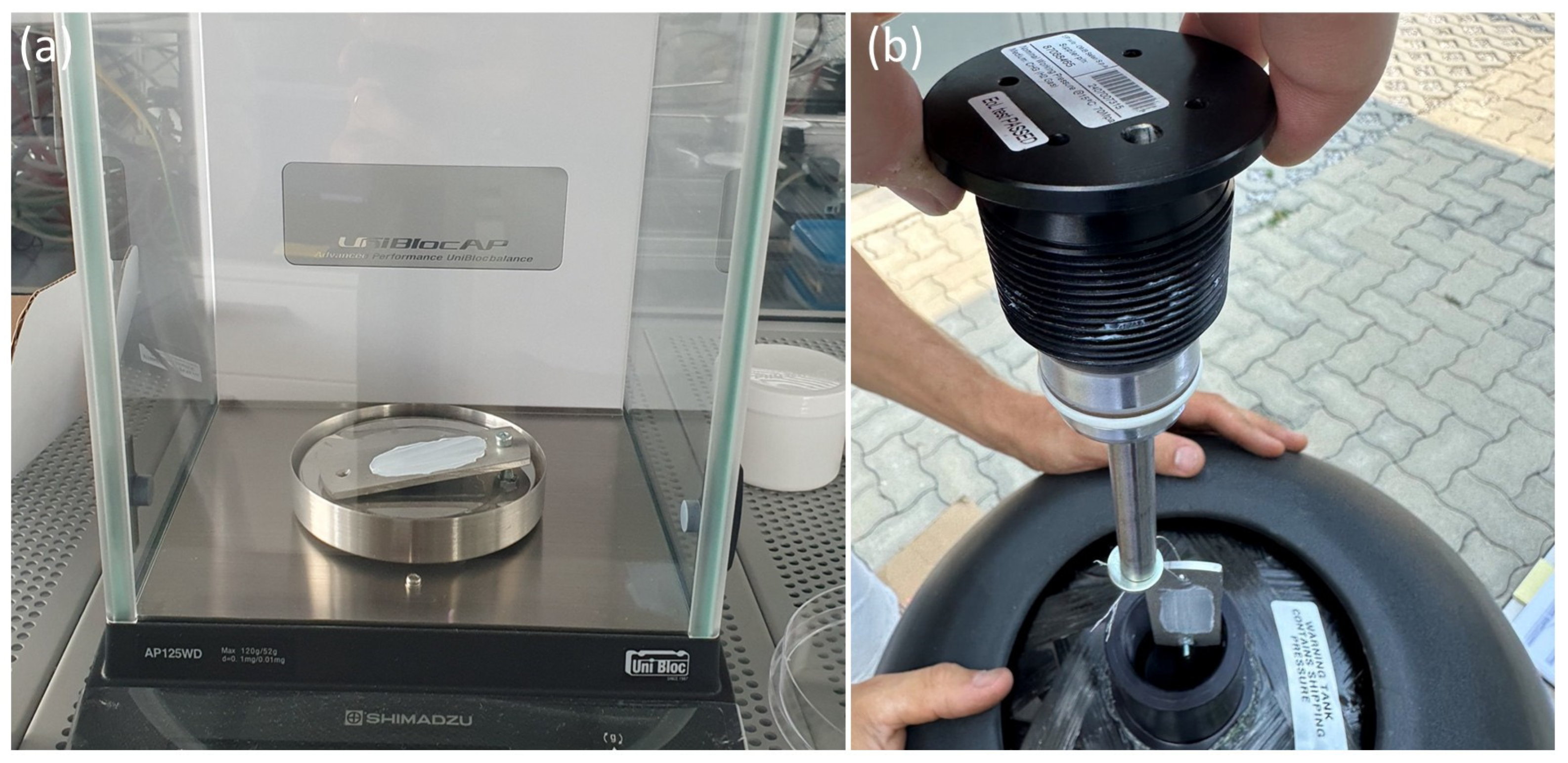
Candidate lubricants were introduced into the Type IV tank (76 L, Hexagon Purus ASA, Oslo, Norway) using stainless steel sinter plates (AISI 316L (1.4404), ca. 30 × 100 × 5 mm3), selected for their high mechanical stability and proven material compatibility in hydrogen test systems [39]. Prior to use, plates were precision-cleaned by rinsing with distilled water and cleaning in an ultrasonic bath, where they were fully immersed in isopropanol for 30 min at 80 °C. Afterwards, the sinter plate was dried at 100 °C for 30 min. Cleanliness was confirmed by comparing the pristine and post-cleaning mass of the sinter plate using a Shimadzu AP125WD precision scale (Shimadzu Handelsgesellschaft mbH, Korneuburg, Austria, average of three measurements). For lubricant application, the formulation was first homogenized until no phase separation was observed. Then, 1.000 g ± 0.002 g of lubricant was applied as a thin layer on both sides of the sinter plate using a metal spatula, using special care to avoid the inclusion of air bubbles and film inhomogeneities (Figure 2a). This step was carried out under cleanroom conditions (ISO Class 7 [40]) to minimize the risk of air entrapment, localized concentration gradients, and subsequent non-uniform lubricant degradation during H2 exposure. The quantity of the tested lubricants was deliberately set to 1 g to simulate a worst-case overlubrication scenario. Since connector and fastener sizes are not standardized for hydrogen refueling infrastructure and FCEV tanks, commercial solutions using ISO M45 [41] threads (76 L, Hexagon Purus ASA, Oslo, Norway, type IV hydrogen tank) were used to guide realistic lubrication scenarios. Based on this reference, an active flank area of approximately 60 cm2 was estimated. Assuming lubricant densities of 1.0 g cm−3 and film thicknesses of 10–50 µm, realistic lubrication requires between 0.06 g and 0.30 g of lubricant. Consequently, the selected 1 g far exceeds typical application amounts, providing a robust safety margin for evaluating lubricant compatibility under conservative testing conditions.

2.2. Integration into the Test System

The sinter plate with the lubricant layer was mounted securely at the rear end of the commercially available Type IV hydrogen storage tank (76 L, Hexagon Purus ASA, Oslo, Norway, Figure 2b). For this, the test assembly (sinter plate with lubricant layer) was suspended on a stainless steel wire attached to a 10 cm stainless steel rod, which was fastened to the threaded port of the tank’s end plug. The test assembly was carefully inserted into the tank, preventing physical contact with any external and internal tank components. The position at the rear end was chosen to guarantee direct exposure to pressurized hydrogen during refueling while ensuring reproducible positioning across all test runs. Previous studies on fast filling of Type IV hydrogen tanks indicate that temperature distributions can be non-uniform and that regions near the tank end may experience elevated thermal loads and pronounced temperature gradients [42]. Thus, this location is selected not only as a representative position in terms of maximum thermal stress, but also because the end plug (‘boss’) is typically lubricated under standard operating conditions. In this way, the position of the subsequent end-use application is reproduced as closely as possible to its real configuration.

2.3. Hydrogen Refueling

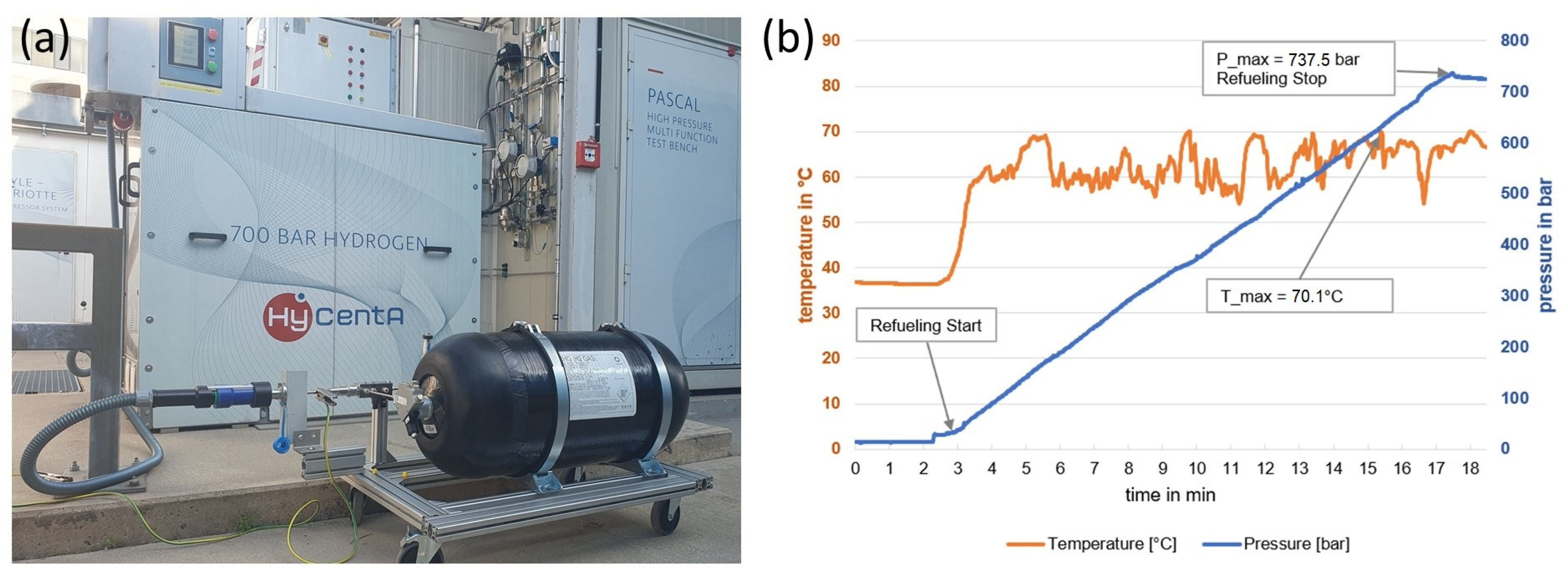
Following test assembly integration, the tank was connected to the refueling infrastructure at HyCentA using a standard OTV setup (H2 OTV, OMB Saleri S.p.A. SOCIETÀ BENEFIT, Brescia, Italy) according to manufacturer specifications. The system was subsequently purged with nitrogen (Linde Gas GmbH Österreich, Stadl-Paura, Austria, min. 99.998% purity, 2 × 12 bar cycles) to displace residual atmospheric gases and ensure no leakages. This was followed by flushing with min. ISO 14687:2025 Grade D hydrogen and filling the tank to 20 bar (Figure 3a). Afterwards, the test protocol adhered to standardized SAE J2601 refueling profiles [36]. The boundary conditions for the refueling setup are defined by a non-communication (no-com) fueling protocol with an initial pressure of 10 bar, a target final pressure of 742 bar, and hydrogen pre-cooling at –20 °C. These conditions necessitate the application of SAE J2601, Table B-70 [36]. At an ambient temperature of 35 °C, this corresponds to a required pressure ramp rate of 44 bar/min, which was rigorously maintained at the dispenser, where internal tank pressure and temperature were continuously monitored (Figure 3b).

3. Analytic Measurements

When the target pressure of 742 bar was reached, gas purity was assessed within a 15 to 30 min time window after filling to (i) verify that hydrogen purity (Grade D) was maintained during the refueling process, and (ii) establish a baseline for H2 quality (t = 0) when evaluating lubricant suitability over defined test periods. This approach ensured that any increase of ISO 14687:2025-regulated impurities detected during the study could be attributed to the presence of the lubricant rather than conditioning or pre-test contamination. Over the test period, the system was held under static conditions. For pre-screening, a dwell period of 24 h was used to investigate lubricant formulation stability. In contrast, for the full qualification protocol, dwell periods of up to 23 days were defined to simulate typical dwell intervals between refueling events (based on 10,000 km/year and approximately 600 km driving distance per refill). Potential leaching, outgassing, or degradation of the lubricant was assessed via the following combined analysis approach.

3.1. Optical and Gravimetric Assessment of Lubricant Films (Test A)

After the protocol dwell period (24 h for pre-screening and up to 23 days for full qualification), the tank was depressurized according to the tank manufacturer specifications, and the test assemblies were retrieved from the tank internals. The uniformity of the lubricant layer was assessed via optical comparison before and after exposure, and lubricant losses were quantified by precision weighing using a Shimadzu AP125WD precision scale (Shimadzu Handelsgesellschaft mbH, Korneuburg, Austria, average of three measurements).

3.2. Gas Analysis Aligned with ISO 14687:2025 Grade D (Test B)

Hydrogen purity assessment was performed in alignment with ISO 14687:2025 Grade D using a Matrix MG 5 real-time Fourier transform infrared (FTIR) gas analyzer (Bruker, Austria Gmbh, Vienna, Austria) and a ComboSense® (V&F Analyse- und Messtechnik GmbH, Absam, Austria), which combines an ion–molecule reaction mass spectrometer (IMR-MS) with an electron impact mass spectrometer (EI-MS).
The FTIR spectrometer contains a mercury–cadmium–telluride detector cooled with liquid nitrogen, and a RocksolidTM interferometer (Bruker Optics GmbH & Co. KG, Ettlingen, Germany) featuring permanent alignment. A 5 m multi-reflection gas cell is used with an aluminum body coated in nickel, zinc selenide (ZnSe) windows, and gold-coated mirrors. The gas cell is maintained at a temperature of 25 °C. The spectral resolution is below 0.5 cm−1, with a spectral rate of 0.5 cm−1/s. The FTIR’s housing, containing the beam path outside the gas cell, is enclosed in a Zarges® box (ZARGES GmbH, Weilheim, Germany) and is continuously purged with nitrogen at a flow rate of 800 mL/min. This purging creates an environment in the beam path that is free from environmental gases. The FTIR system is designed to provide high-precision quantification of gaseous compounds, even at very low concentrations, without requiring calibration. Detection of analytes is achieved using reference spectra provided by the manufacturer (Bruker Austria Gmbh, Vienna, Austria), and concentrations are determined from respective signal intensities according to the Lambert–Beer law.
The ComboSense® is a combined system that integrates an electron impact mass spectrometer (EI-MS) and an ion–molecule reaction mass spectrometer (IMR-MS) within a single analyzer. It employs different ion sources, such as mercury (Hg), xenon (Xe), and krypton (Kr), depending on the analyzed compound, and is calibrated via enhancement calibration to identify interference patterns and linearization models.
Analytical conditions based on tested compounds are detailed in Table S1 in the Supplementary Materials. For measurement, the H2 gas was directly fed from the Type IV tank system to the FTIR/IMR-EI-MS analysis section using 12 m stainless steel tubing with SiO2 coating. Data processing and analysis were carried out using OPUS GA for the FTIR measurements and V&F Client 2.5 for the IMR-EI-MS data. Statistical errors were found to outweigh systematic errors, and overall uncertainty was expressed as three times the standard deviation of the mean value.

3.3. Filter-Based Particulate Matter Assessment (Test C)

During tank defueling, particulate matter was collected via inline filtration. An in-stream filter (FGLP04700—0.22 µm pore size, hydrophobic PTFE, 47 mm membrane, MilliporeSigma (Merck KGaA), Darmstadt, Germany) was pre-conditioned for 24 h in an ISO Class 7 cleanroom environment using a HEPA filter horizontal flow hood [43]. Additionally, the filter holder components were cleaned in an ultrasonic bath of de-ionized water for 20 min, followed by drying in an ISO Class 7 cleanroom environment for 48 h. Then, the pre-conditioned filter was installed between the fueling nozzle and the FCEV receptacle using a hydrogen particle sampler adapter. In alignment with ASTM D7650-21 [44] recommendations, check valves were placed upstream of the tank to prevent reverse gas flow through the filter during defueling.
After defueling, the filter was collected and microscopically assessed using a Zeiss Stemi 305 optical microscope (Carl Zeiss GmbH, Vienna, Austria, 4–200× magnification, 1.25 µm resolution). The particulate load was determined by precision weighing using a Shimadzu AP125WD precision scale (Shimadzu Handelsgesellschaft mbH, Korneuburg, Austria, average of three measurements) in a cleanroom environment.

3.4. Testing and Protocol Completion Criteria

To enable early identification of lubricant formulations with a high risk of degradation or H2 incompatibility, the testing and protocol completion criteria for the simplified pre-screening protocol are outlined in Table 1. This abbreviated approach comprises only the optical assessment (Test A) and gas analysis aligned with ISO 14687:2025 Grade D (Test B), thereby allowing for rapid screening of prospective lubricant candidates within 24 h. For the full qualification protocol, mandatory testing and protocol completion criteria are summarized in Table 2. Protocol activities, including a defined timeline for the start and end of Test A, Test B, and Test C, are presented in chronological order.

4. Lubricant Suitability Criteria

To assess the contamination potential of lubricants used in high-pressure hydrogen components in FCEVs, the applied methodology included: (i) optical inspection, (ii) gas purity analysis, and (iii) particulate matter analysis. These assessments were selected to detect both short-term and long-term degradation phenomena that could release contaminants into the hydrogen stream and compromise fuel cell system integrity.
First, the optical inspection (Test A) was used to enable elimination of unstable lubricant formulations. Optical stability is considered a key parameter for evaluating physicochemical long-term stability. In particular, in view of the regulatory service life of hydrogen tanks in vehicles of up to 15 years, ensuring stability and sustained functionality is essential [45]. For the pre-screening protocol, the lubricant layer appearance was assessed visually after one day of exposure to high-pressure hydrogen, investigating short-term effects of hydrogen and enabling elimination of unstable lubricant candidates without prolonged testing. In the full lubricant qualification protocol, the optical appearance of the lubricated test assemblies was compared when pristine (day 0) and at the end of the test after extraction from the hydrogen tank in week 4. In both protocols, any form of discoloration, detachment, flaking, spreading, or changes in surface morphology—conditions that could minimize sealing function and lead to persistent tank contamination with the risk of indeterminate release of impurities—was considered unacceptable. Thus, acceptance criteria for the optical inspection were defined as follows:
  • Pass: No visible changes in lubricated surface uniformity, adhesion, or appearance.
  • Fail: Any visual signs of chemical or physical degradation, such as discoloration, detachment, flaking, spreading, or changes in surface morphology.
The test protocols continue with in-line monitoring of the hydrogen gas purity. In the pre-screening protocol, gas purity was assessed after 1 day of hydrogen exposure. In contrast, for the full qualification protocol, gas purity was evaluated four times up to week 4 to quantitatively ensure that Grade D hydrogen can be delivered to the PEM-fuel cell over representative refill cycles. Gas analysis was conducted in alignment with the ISO 14687:2025 standard, and acceptance criteria were defined as follows:
  • Pass: No analyte exceeds ISO 14687:2025 impurity limits at any time point.
  • Fail: Exceedance of any ISO-regulated limit.
Then, particulate matter release is assessed only in the full qualification protocol after the total dwell period of the test assembly in the tank. For this, pre-conditioned analytical-grade PTFE filters were placed downstream of the tank outlet to capture entrained solids during controlled depressurization. Filters were weighed and examined using an optical microscope before and after testing to assess both mass change and visual particulate loading. While ISO 14687:2025 does not prescribe a specific particle testing method, this dual-mode approach provides a reproducible means of verifying particulate matter compliance and detecting degradation phenomena not apparent in gas-phase analysis. Acceptance criteria were defined as follows:
  • Pass: ≤1 mg/kg particulate load in hydrogen.
  • Fail: Particulate load above the ISO threshold.
To define the overall protocol outcome, Table 3 summarizes the acceptance criteria and decision logic for the different evaluation scenarios. Specifically, for the pre-screening protocol, a lubricant candidate is classified as potentially suitable if it meets both the optical inspection and gas purity acceptance criteria after one day of hydrogen exposure. In this context, potentially suitable indicates general formulation stability under high-pressure hydrogen during short-term (<24 h) exposure, but does not constitute full qualification for application in FCEV drive trains. A failure in either one or both of the pre-screening tests results in the classification of unsuitable, thereby eliminating the lubricant from further consideration for FCEV drive train applications without additional testing. Similarly, following the full qualification protocol, a lubricant is classified as suitable for use in FCEV drive trains applications only if all three tests (optical inspection, gas purity, and particulate matter) are passed in accordance with the defined acceptance criteria. If the investigated material fails one or more tests, the overall protocol result is designated as unsuitable. Additionally, in the case that a test result is inconclusive while all other criteria have been met, the test must be repeated, as overall protocol completion requires that all individual criteria be satisfied. In contrast, if, for instance, a lubricant fails the optical inspection criterion (Test A), and Test B and/or Test C are inconclusive, the overall outcome is still classified as unsuitable, following a conservative failure assessment approach.
Collectively, these criteria enable a structured and comprehensive assessment of lubricant suitability, aligned with relevant international standards, including ISO 14687:2025.

5. Results

To evaluate the suitability of lubricants under high-pressure H2 conditions, the pre-screening and full qualification protocol, including test assembly preparation, insertion into the hydrogen tank, refueling, and subsequent analytic evaluation, were applied as described in Section 2 and Section 3 to different lubricants.
First, three formulations with limited information regarding their chemical compositions were provided as semi-masked samples for evaluation in accordance with the pre-screening protocol. The investigation of these semi-masked lubricants was designed to reflect practical scenarios, in which products, protected by confidentiality or trade-secret constraints, must be assessed based solely on the restricted descriptions made available by the manufacturers. Thus, to rapidly evaluate formulation stability and compatibility with high-pressure hydrogen conditions, the simplified pre-screening protocol was applied. The three semi-masked lubricants were assigned internal acronyms and were evaluated based only on supplier-provided composition descriptors and declarations, including a statement of ‘no intentionally added PFAS’ that was not independently verified by targeted PFAS analysis within the present study. The chemical composition information was provided as follows: (i) SBGL, a silicone base lubricant formulated with aromatic silicone base oil and lithium thickener, chosen for its enhanced oxidation resistance and thermal stability; (ii) MOSS, a high-purity mineral oil thread compound, composed of mineral oil and special solid lubricants, selected for its anti-seize properties and use in threaded connections, such as screws, bolts, and nuts; and (iii) SC, a silicone compound composed of silicone oil and inorganic thickener, which provides a wide service temperature, excellent water resistance, low vapor pressure, and low volatility.
For the full qualification protocol, MOLYKOTE® HP-300 Grease (DuPont Specialty Products GmbH & Co. KG, Wiesbaden, Germany) [46], a fully fluorinated lubricant with PFPE base oil, was supplied by DuPont. It was selected for its low vapor pressure, excellent thermal stability, resistance to chemicals and solvents, and broad compatibility with plastics and elastomers.
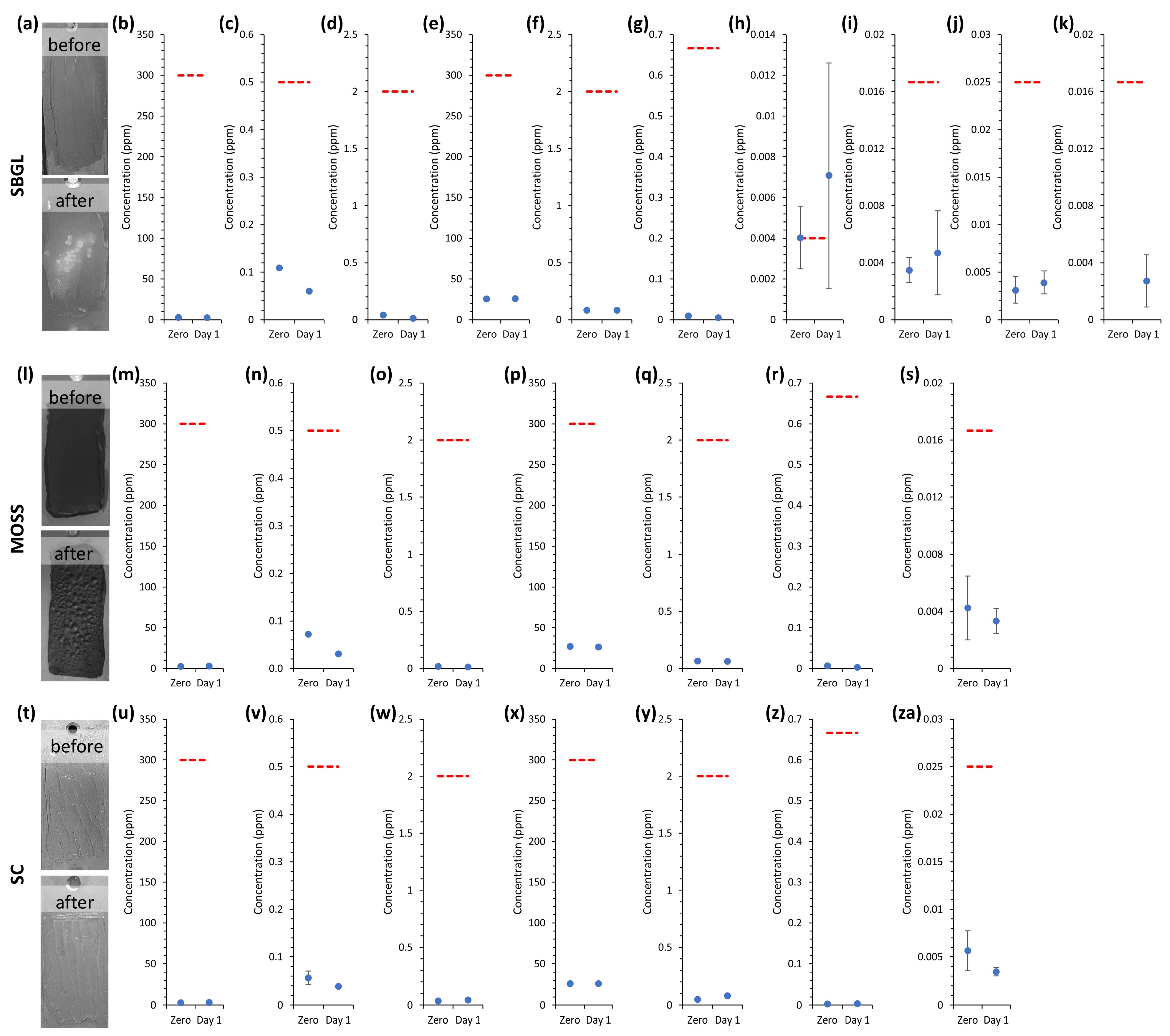
In the pre-screening of the three semi-masked formulations, SBGL exhibited a distinct change in the optical appearance of the lubricant layer between the beginning and end of Test A. The initially transparent film became opaque and developed topographical roughness after one day of hydrogen exposure (Figure 4a). These visual alterations potentially indicate degradation processes affecting the molecular structure or surface composition of the lubricant. Additionally, gas analysis revealed increased concentrations of tert-butyl mercaptan and the halogenated species trichloroethylene, dichloroethane, and the combined fraction of trichloromethane and dichlorobromomethane (Figure 4b–k), supporting the assumption that contaminants were released into the hydrogen stream. Although the total concentration of halogenated compounds remained below the ISO 14687:2025 Grade D limit of 0.05 ppm, the increase of tert-butyl mercaptan warrants particular attention. After 24 h under the high-pressure hydrogen conditions, its concentration reached 0.007 ppm, exceeding the ISO 14687:2025 Grade D threshold. However, the reference measurement indicated that tert-butyl mercaptan was already present at a concentration of 0.004 ppm at the beginning of the test, matching the limit for Grade D purity. Furthermore, the measurement uncertainty at the 24 h time point was larger than 60% of the reported mean value, preventing definitive conclusions regarding regulatory limit exceedance. Thus, for SBGL, Test A was rated a failure, while Test B was considered inconclusive. Accordingly, SBGL was classified as unsuitable based on the optical failure criterion, with the inconclusive gas analysis result not affecting the overall decision outcome.
In the case of MOSS, the black lubricant developed a blistered surface morphology within 24 h of H2 exposure (Figure 4l). This was accompanied by reduced adhesion to the stainless steel sinter plate, indicating interaction of the lubricant layer and the hydrogen gas in the tank. In contrast, gas analysis revealed no relevant changes in the hydrogen gas purity, with detected contaminants remaining at concentrations well below ISO 14687:2025 Grade D thresholds (Figure 4m–s). These observations suggest that the visual changes are unlikely to result from outgassing of volatile components or chemical degradation, but are more consistent with physical changes to the formulation, such as potential phase separation. Such physical alterations increase the risk of potential particulate matter formation and downstream PEMFC contamination in FCEVs, leading to the disqualification of MOSS based on the optical inspection criterion.
The SC lubricant passed the optical inspection, showing no changes in surface structure and color within the one-day exposure period (Figure 4t). Furthermore, gas analysis revealed only minor variations in contaminant concentrations. Indeed, only a few species, such as hydrocarbons, were detected in the gas stream, none of which increased over the test period or exceeded ISO 14687:2025 limits (Figure 4u–za and Table S2 in the Supplementary Materials), confirming Grade D quality. Thus, SC successfully passed the pre-screening protocol, demonstrating formulation stability under high-pressure conditions over 24 h.
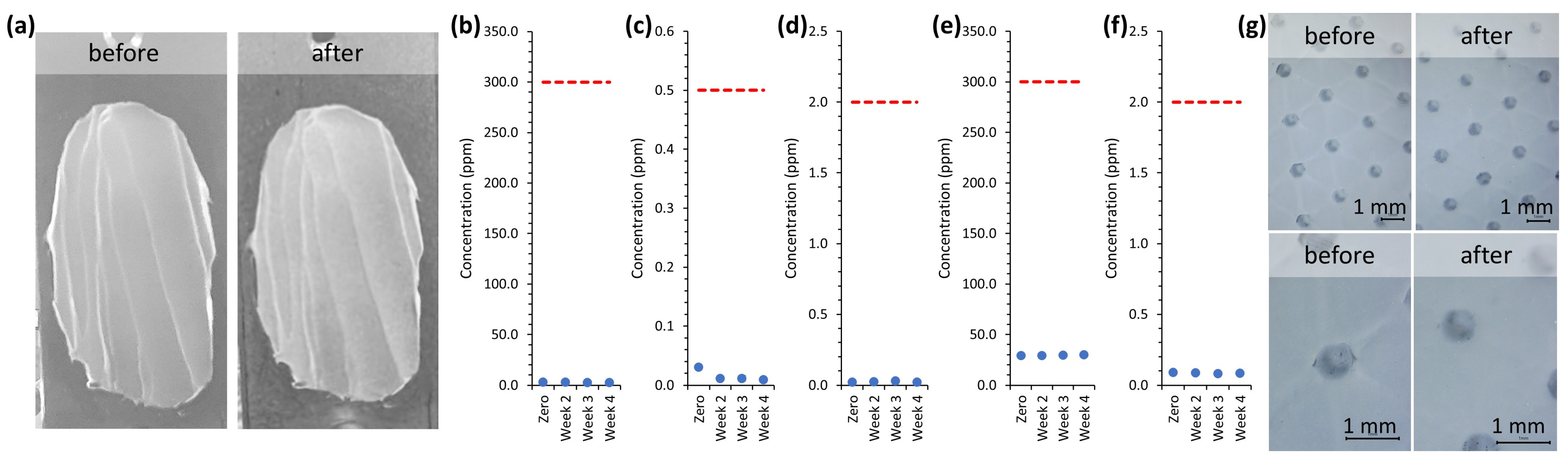
In the full qualification protocol, MOLYKOTE® HP-300 Grease maintained its original surface morphology and visual integrity over the 23-day exposure period, fulfilling the optical inspection criterion according to Section 4 (see Figure 5a). Additionally, gas purity analysis revealed no detectable increase in ISO 14687:2025-regulated impurities over the total dwell period. Indeed, most analytes remained below the limit of detection throughout, and only argon, butane, carbon dioxide, helium, and M29, a mass fragment typical for small organic molecules, were observed after the initial reference measurement (see Figure 5b–f and Figure S2 in the Supplementary Materials). These analytes stayed below ISO 14687:2025 thresholds within the 23-day period, consistently meeting Grade D specification in two separate test runs (see Figure S3 and Tables S3 and S4 in the Supplementary Materials). In the particulate matter assessment, analytical-grade filters placed downstream during controlled defueling showed no visible particles under optical microscopy (Figure 5g) and no increase in mass after filtering 3.1 kg H2 from the tank. These findings indicate that MOLYKOTE® HP-300 Grease does not release measurable amounts of volatile or solid contaminants during extended exposure to high-pressure hydrogen conditions, passing all acceptance criteria for application in FCEV drive trains.

6. Discussion

6.1. Lubricant-Based Contamination Risks and Implications for Product-Specific Qualification

The findings of this study, summarized in Table 4, indicate that the contamination risk for PEMFC systems is strongly dependent on the specific lubricant product. In the pre-screening trial, which was designed as a rapid gatekeeping step to assess formulation stability and eliminate unsuitable candidates without extended testing, two of the three tested semi-masked formulations did not meet the combined acceptance criteria. Both SBGL and MOSS failed the pre-screening evaluation based on optical inspection, as visible changes in morphology and adhesion behavior were observed. Gas analysis after one day of hydrogen exposure was inconclusive for SBGL and compliant with ISO 14687:2025 Grade D for MOSS, indicating that the observed visual changes cannot be directly associated with volatile contamination above the applied threshold criteria. Since the protocol was not designed to identify degradation pathways or underlying physicochemical mechanisms, the origin of these visible alterations cannot be determined from the present data. Nevertheless, such changes are relevant from an application perspective since flaking, detachment, or particulate formation can contribute to long-term PEMFC damage or impair sealing functionality. As illustrated by these examples, the optical inspection criterion in the pre-screening protocol complements ISO 14687:2025-based gas analysis and provides a simple but effective means of identifying formulation instability and potential contamination-related concerns that may not be captured by gas-quality monitoring alone.
In the case of SC, both acceptance criteria were met in the pre-screening stage. However, this result should not be interpreted as evidence for silicone-based lubricants as a broader material class. Publicly available information on the hydrogen compatibility of individual lubricant products remains limited, and only a small number of in situ fuel cell studies are available. While voltage losses have been reported for certain silicone-containing sealing materials during in situ testing [28], the differing outcomes observed for SBGL, SC, and the materials reported in the literature highlight that contamination risk cannot be inferred reliably from the nominal base material or material class stated in manufacturer descriptions alone. In particular, the possible influence of undisclosed additives, impurities, or formulation-specific processing effects cannot be assessed without more detailed compositional information, which supports the need for product-specific qualification for the use in high-pressure hydrogen FCEV tanks.
For the full qualification protocol, the results obtained for the MOLYKOTE® HP-300 Grease show that this specific PFPE-based product met the acceptance criteria under the investigated conditions. Literature on fluorinated materials reports properties such as low vapor pressure, chemical inertness, and thermal stability [47], which may provide useful context for interpreting this favorable outcome. In addition, similar fluorinated materials showed no significant impact on fuel cell performance during several hours of in situ exposure testing [28], and several fluorinated products are described by manufacturers as suitable for hydrogen applications (Table S5 in the Supplementary Materials). However, these observations should be regarded as contextual support rather than direct evidence for fluorinated lubricants as a class in the present application. Both the number of fluorinated products assessed in this study and the amount of publicly available in situ evidence remain limited. Moreover, detailed compositional data, characterization results, and qualification criteria for high-pressure hydrogen applications are rarely disclosed by manufacturers. Accordingly, no class-level conclusion can be drawn for fluorinated lubricants in general. This is particularly relevant considering that ISO 14687:2025 Grade D specifies impurity limits as low as 4 ppb, highlighting that even trace levels of contaminants could impact hydrogen quality. Consequently, it is emphasized that contamination risk cannot be assessed solely on the basis of the reported formulation type, and lubricant qualification on a product-specific basis is considered essential.

6.2. Protocol Applicability, Advantages and Constraints

While in situ FC testing is planned for the lubricants tested in this study to allow detailed comparison with other materials using the same methodology [48], the advantages and limitations of the protocol presented here warrant discussion. In situ testing directly measures the time-resolved influence of materials on FC performance, but the setup is complex, requiring multiple components, sensors, controls, and often specialized operational expertise. In contrast, the protocols presented here do not assess impact on FC performance directly. Instead, they evaluate lubricants for refueling of high-pressure hydrogen tanks using a simple and conservative analytical workflow, combining optical and gravimetric assessment with hydrogen gas purity evaluation aligned with ISO 14687:2025 Grade D, and, for full qualification, additional filter-based particulate matter analysis. Moreover, the complexity and knowledge requirements of the presented method are less demanding compared to in situ testing setups. The approach relies on a commercially available Type IV tank and standardized SAE J2601 refueling profiles, which reproduces the relevant exposure under realistic conditions and targets post-dispensing contamination along the same gas pathway that would feed an FC system. In the present implementation, gas purity was monitored in-line. However, the protocol can in principle also be executed using external gas analysis facilities provided that appropriate sampling procedures are applied, which may further lower the barrier for adoption. A practical limitation is throughput: only one lubricant can be assessed per tank campaign, and small-scale tests were intentionally avoided to preserve realistic conditions. Nevertheless, operator workload is low since intervention is required mainly at the start and end of a test and at defined intermediate analysis time points, while the system can remain unattended during dwell periods.
With respect to robustness and reproducibility, the testing framework is anchored in internationally recognized standards for both exposure and acceptance criteria, providing a structured basis for lubricant assessment under realistic refueling conditions. However, the broader generalizability of the protocol must be interpreted in the context of the presented validation scope: three lubricant formulations were assessed in the 24 h pre-screening stage, while full qualification was completed for only one lubricant. Accordingly, the current dataset primarily demonstrates feasibility and decision logic rather than establishing cross-comparability across lubricant products and classes. Nonetheless, the examples presented in this work demonstrate that the pre-screening stage is suitable for identifying formulation stability and potential contamination risk within 24 h, and full qualification outcomes are reproducible across independent test runs (see Tables S3 and S4 in the Supplementary Materials). However, limited knowledge can be gained with respect to the observed formulation changes and contaminant release, as the testing framework is not intended to elucidate underlying degradation mechanisms. It is also noted that statistically robust conclusions will require expanded material sets and a larger number of replicates.
Beyond mobile applications, the authors note that the methodological logic of this work may also be transferable to stationary hydrogen systems in the future. This transferability is not validated in the present work and will require dedicated testing. However, boundary conditions are similar for both applications. The laboratory setup, which fulfills hydrogen purity requirements equivalent to ISO 14687:2025 Grade D, is likewise capable of meeting more stringent Grade E specifications associated with stationary fuel cell applications [1]. In such systems, particularly those employing steel tanks, similar physicochemical phenomena are expected. Unlike composite Type IV tanks in FCEVs, stationary steel vessels are regulated under the Pressure Equipment Directive rather than SAE refueling temperature-management protocols. Consequently, higher fill temperatures can be permissible. This results in locally elevated temperatures during filling, potentially intensifying lubricant volatilization and degradation processes, which could be evaluated based on the optical and gas purity tests. Furthermore, stationary installations often comprise extended piping networks and steel fittings, which might contribute to an increased particle load originating from welding and manufacturing residues. The inclusion of particulate matter assessment in the transferred full qualification pathway would therefore be particularly relevant for such scenarios and could be extended to the pre-screening stage without changing the overall workflow.
Combined, the pre-screening and full qualification protocols provide a staged framework to identify unstable lubricant formulations early and to support subsequent full qualification of selected candidates under application-relevant conditions.

7. Conclusions

Testing protocols for evaluating lubricant-derived contamination in high-pressure hydrogen systems were developed. A simplified pre-screening protocol was defined based on optical inspection and gas purity requirements, enabling rapid evaluation and potential candidate elimination based on lubricant formulation stability within 24 h. Additionally, the full qualification approach integrates optical inspection, in-line gas purity monitoring over 23 days, and particulate matter analysis following realistic refueling events. By carefully controlling test conditions and adhering to established international standards for refueling and gas quality, the protocols provide a structured and conservative method to qualify lubricants for use in FCEV tanks at different evidence levels.
The staged framework was applied to four lubricants to demonstrate feasibility of the decision logic under realistic 700 bar refueling exposure. Three candidates were assessed via pre-screening: one silicone-based formulation met the 24 h acceptance criteria and was classified as potentially suitable, whereas two other lubricants were classified as unsuitable due to formulation instability. In the full qualification protocol, the PFPE-based MOLYKOTE® HP-300 Grease met all acceptance criteria over 23 days in two separate test runs, resulting in the classification of suitable. The observed product-specific differences show that lubricant compatibility cannot be inferred reliably from nominal material class or supplier descriptions alone. Instead, application-relevant and product-specific qualification is required. The proposed staged framework therefore provides a practical pre-normative basis for material selection, supplier qualification, inter-laboratory validation, and future standardization of compatibility testing for lubricants in FCEV hydrogen tanks. In this way, the protocol supports both safer integration of lubricants into high-pressure hydrogen tank systems and the long-term reliability of PEMFC-based mobility applications.

Supplementary Materials

The following supporting information can be downloaded at: https://www.mdpi.com/article/10.3390/hydrogen7020083/s1, Figure S1: (a–j) Gas analysis data of SBGL with (a) argon, (b) butane, (c) carbon dioxide, (d) helium, (e) M29, (f) propylene, (g) tert-butyl mercaptan, (h) dichloroethane, (i) combined fraction of trichloromethane and dichlorobromomethane and (j) trichloroethylene; (k–q) gas analysis data of MOSS with (k) argon, (l) butane, (m) carbon dioxide, (n) helium, (o) M29, (p) propylene and (q) combined fraction of trichloromethane and dichlorobromomethane; (r–x) gas analysis data of SC with (r) argon, (s) butane, (t) carbon dioxide, (u) helium, (v) M29, (w) propylene and (x) dichloroethane; Figure S2: Gas analysis results of DuPont™ MOLYKOTE® HP-300 Grease, showing contaminant concentrations with error bars of (a) argon, (b) butane, (c) carbon dioxide, (d) helium, (e) M29; Figure S3: Gas analysis results of DuPont ™ MOLYKOTE® HP-300 Grease (2nd run) with ISO 14687:2025 limits presented in red lines and contaminant concentrations of (a) argon, (b) butane, (c) carbon dioxide, (d) helium, (e) M29, (f) propylene, (g) combined fraction of trichloromethane and dichlorobromomethane; (h–n) contaminant concentrations with error bars of (h) argon, (i) butane, (j) carbon dioxide, (k) helium, (l) M29, (m) propylene, (n) combined fraction of trichloromethane and dichlorobromomethane; Table S1: Overview of Equipment used for ISO 14687 contaminant analysis; Table S2: Hydrogen quality analysis result of SC lubricant, showing H2 quality Grade D: 4.5 (99.997%)* after 1 day of exposure in a 700 bar Type IV vehicle tank; Table S3: Hydrogen quality analysis result of MOLYKOTE® HP-300 Grease (run 1), showing H2 quality Grade D: 4.5 (99.997%)* within 23 days of exposure in a 700 bar Type IV vehicle tank; Table S4: Hydrogen quality analysis result of MOLYKOTE® HP-300 Grease (run 2), showing H2 quality Grade D: 4.5 (99.997%)* within 23 days of exposure in a 700 bar Type IV vehicle tank; Table S5: Fluorinated lubricants classified for hydrogen application. Ref. [28] is added in the Supplementary Materials.

Author Contributions

Conceptualization, L.A.B., T.S. and K.A.; methodology, L.A.B., T.S., K.A., T.H. and V.R.; validation, T.S., T.H., V.R., S.B. and A.T.; formal analysis, T.H., V.R., S.S. and M.B.; investigation, T.H., V.R., S.S. and M.B.; resources, K.A.; data curation, L.A.B. and T.S.; writing—original draft preparation, L.A.B.; writing—review and editing, T.S., K.A. and A.T.; supervision, S.B. and A.T.; project administration, T.S.; funding acquisition, T.S. and A.T. All authors have read and agreed to the published version of the manuscript.

Funding

This research received funding by the HyCentA COMET Centre within the COMET—Competence Centers for Excellent Technologies—Programme, funded by BMIMI, BMWET, as well as the cofinancing federal provinces Styria, Upper Austria, Tyrol, and Vienna (grant number 892427).

Data Availability Statement

The data that support the findings of this study are available from the corresponding author upon reasonable request.

Acknowledgments

The authors thank DuPont for the cooperation and financial support. HyCentA is a COMET Centre within the COMET—Competence Centers for Excellent Technologies—Programme and is funded by BMIMI, BMWET, as well as the cofinancing federal provinces Styria, Upper Austria, Tyrol, and Vienna. COMET is managed by FFG. This work was supported by Open Access Funding by the Graz University of Technology. During the preparation of this manuscript, the authors used AI technology, such as large language models, for the purposes of improving language and readability. The authors have reviewed and edited the output and take full responsibility for the content of this publication.

Conflicts of Interest

Lea A. Brandner, Thomas Stöhr, Thomas Hafner, Verena Reiter, Sebastian Scheikl, Melisa Bijedic, Stefan Brandstätter, and Alexander Trattner were employed by the HyCentA Research GmbH Co., Ltd. Krystel Araneda was employed by the DuPont Specialty Products GmbH & Co. KG. The remaining authors declare that the research was conducted in the absence of any commercial or financial relationships that could be construed as a potential conflict of interest. DuPontTM, the DuPont Oval Logo, and all trademarks and service marks denoted with TM, SM or ® are owned by affiliates of DuPont de Nemours, Inc. unless otherwise noted. Nothing contained herein shall be construed as a representation that any recommendations, use, or resale of the product or process described herein is permitted and complies with the rules or regulations of any countries, regions, localities, etc., or does not infringe upon patents or other intellectual property rights of third parties. In addition to anything stated herein, the information provided herein is based on data DuPont believes to be reliable as of the date hereof and is provided at the request of and without charge to our customers. This information is not intended as a substitute for any testing you may conduct to determine for yourself the suitability of our products for your particular purpose. Since conditions for use are outside the DuPont’s control, DUPONT DE NEMOURS, INC. AND ITS AFFILIATES MAKE NO WARRANTIES, EXPRESSED OR IMPLIED, INCLUDING BUT NOT LIMITED TO WARRANTIES OF MERCHANTABILITY OR FITNESS FOR A PARTICULAR PURPOSE AND ASSUMES NO LIABILITY IN CONNECTION WITH ANY USE OF THIS INFORMATION. This information is not intended as a license to operate under or a recommendation to infringe any trademark, patent or technical information of DuPont or other persons covering any material or its use. All images and figures were created by HyCentA and are neither licensed by, nor represent official materials from DuPont.

Abbreviations

The following abbreviations are used in this manuscript:
FCEVFuel cell electric vehicle
PEMProton exchange membrane
PEMFCProton exchange membrane fuel cells
OTVOn-tank valve
NRLNational Laboratory of the Rockies
FTIRFourier transform infrared
IMR-MSIon–molecule reaction mass spectrometer
EI-MSElectron impact mass spectrometer

References

  1. ISO 14687:2025(en); Hydrogen Fuel Quality—Product Specification. International Organization for Standardization: Geneva, Switzerland, 2025.
  2. ISO 21087:2019(en); Gas Analysis—Analytical Methods for Hydrogen Fuel—Proton Exchange Membrane (PEM) Fuel Cell Applications for Road Vehicles. International Organization for Standardization: Geneva, Switzerland, 2019.
  3. ISO 19880-8:2024(en); Gaseous Hydrogen—Fuelling Stations, Part 8: Fuel Quality Control. International Organization for Standardization: Geneva, Switzerland, 2024.
  4. SAE J2719_202003; Hydrogen Fuel Quality for Fuel Cell Vehicles. SAE International: Warrendale, PA, USA, 2020.
  5. CEN/TS 17977; Gas Infrastructure—Quality of Gas—Hydrogen Used in Rededicated Gas Systems. Austrian Standards Plus GmbH: Vienna, Austria, 2023.
  6. Deutscher Verein des Gas- und Wasserfaches e.V.—DVGW. DVGW G260—Gasbeschaffenheit: Technische Regel; Deutscher Verein des Gas- und Wasserfaches e.V.: Bonn, Germany, 2021. [Google Scholar]
  7. ÖVGW (Österreichische Vereinigung für das Gas- und Wasserfach). ÖVGW G B210:2021-06—Gas Quality; DIN Media: Berlin, Germany, 2021; Available online: https://www.dinmedia.de/en/technical-rule/oevgw-g-b210/341572969 (accessed on 11 May 2026).
  8. Österreichische Vereinigung für das Gas- und Wasserfach—ÖVGW. Richtlinie H E200: Wasserstoffleitungen—Planung, Errichtung und Erstprüfung von Wasserstoffleitungen, 1st ed.; Österreichische Vereinigung für das Gas- und Wasserfach—ÖVGW: Vienna, Austria, 2023. [Google Scholar]
  9. Arrhenius, K.; Morris, A.; Hookham, M.; Moore, N.; Modugno, P.; Bacquart, T. An inter-laboratory comparison between 13 international laboratories for eight components relevant for hydrogen fuel quality assessment. Measurement 2024, 230, 114553. [Google Scholar] [CrossRef] [Scilit]
  10. Wang, Y.; Pang, Y.; Xu, H.; Martinez, A.; Chen, K.S. PEM Fuel cell and electrolysis cell technologies and hydrogen infrastructure development—A review. Energy Environ. Sci. 2022, 15, 2288–2328. [Google Scholar] [CrossRef] [Scilit]
  11. Camacho, M.d.l.N.; Jurburg, D.; Tanco, M. Hydrogen fuel cell heavy-duty trucks: Review of main research topics. Int. J. Hydrogen Energy 2022, 47, 29505–29525. [Google Scholar] [CrossRef] [Scilit]
  12. Bethoux, O. Hydrogen Fuel Cell Road Vehicles and Their Infrastructure: An Option towards an Environmentally Friendly Energy Transition. Energies 2020, 13, 6132. [Google Scholar] [CrossRef] [Scilit]
  13. Wallnöfer-Ogris, E.; Pertl, P.; Trattner, A. Quasi-stationary UI-characteristic model of a PEM fuel cell–Evaluating the option of self-humidifying operation. Int. J. Hydrogen Energy 2020, 45, 32464–32477. [Google Scholar] [CrossRef] [Scilit]
  14. OENORM EN 17124; Hydrogen Fuel—Product Specification and Quality Assurance for Hydrogen Refuelling Points Dispensing Liquid or Gaseous Hydrogen—Proton Exchange Membrane (PEM) Fuel Cell Applications for Vehicles. Austrian Standards International: Vienna, Austria, 2025.
  15. Wang, X.; Baker, P.; Zhang, X.; Garces, H.F.; Bonville, L.J.; Pasaogullari, U.; Molter, T.M. An experimental overview of the effects of hydrogen impurities on polymer electrolyte membrane fuel cell performance. Int. J. Hydrogen Energy 2014, 39, 19701–19713. [Google Scholar] [CrossRef] [Scilit]
  16. Wallnöfer-Ogris, E.; Poimer, F.; Köll, R.; Macherhammer, M.-G.; Trattner, A. Main degradation mechanisms of polymer electrolyte membrane fuel cell stacks—Mechanisms, influencing factors, consequences, and mitigation strategies. Int. J. Hydrogen Energy 2024, 50, 1159–1182. [Google Scholar] [CrossRef] [Scilit]
  17. Cheng, X.; Shi, Z.; Glass, N.; Zhang, L.; Zhang, J.; Song, D.; Liu, Z.-S.; Wang, H.; Shen, J. A review of PEM hydrogen fuel cell contamination: Impacts, mechanisms, and mitigation. J. Power Sources 2007, 165, 739–756. [Google Scholar] [CrossRef] [Scilit]
  18. Yan, W.-M.; Chu, H.-S.; Lu, M.-X.; Weng, F.-B.; Jung, G.-B.; Lee, C.-Y. Degradation of proton exchange membrane fuel cells due to CO and CO2 poisoning. J. Power Sources 2009, 188, 141–147. [Google Scholar] [CrossRef] [Scilit]
  19. Rajalakshmi, N.; Jayanth, T.T.; Dhathathreyan, K.S. Effect of Carbon Dioxide and Ammonia on Polymer Electrolyte Membrane Fuel Cell Stack Performance. Fuel Cells 2003, 3, 177–180. [Google Scholar] [CrossRef] [Scilit]
  20. Profatilova, I.; Fouda-Onana, F.; Heitzmann, M.; Bacquart, T.; Morris, A.; Warren, J.; Haloua, F.; Jacques, P.-A. Detrimental impact of trace amount of tetrachlorohexafluorobutane impurity in hydrogen on PEM fuel cell performance. Int. J. Hydrogen Energy 2024, 65, 837–843. [Google Scholar] [CrossRef] [Scilit]
  21. Stöhr, T.; Reiter, V.; Scheikl, S.; Klopčič, N.; Brandstätter, S.; Trattner, A. Hydrogen quality in used natural gas pipelines: An experimental investigation of contaminants according to ISO 14687:2019 standard. Int. J. Hydrogen Energy 2024, 67, 1136–1147. [Google Scholar] [CrossRef] [Scilit]
  22. Aarhaug, T.A.; Bacquart, T.; Daniels, C.; Adkins, A.; Wong, Y.; Chen, Z.; Madise, H.; Khaki, S.; Morris, A.S.O.; Clough, P.T.; et al. Hydrogen fuel sampling intercomparisons: Challenges in real-life experiments. Int. J. Hydrogen Energy 2025, 153, 150243. [Google Scholar] [CrossRef] [Scilit]
  23. Beurey, C.; Gozlan, B.; Carré, M.; Bacquart, T.; Morris, A.; Moore, N.; Arrhenius, K.; Meuzelaar, H.; Persijn, S.; Rojo, A.; et al. Review and Survey of Methods for Analysis of Impurities in Hydrogen for Fuel Cell Vehicles According to ISO 14687:2019. Front. Energy Res. 2021, 8, 615149. [Google Scholar] [CrossRef] [Scilit]
  24. Arrhenius, K.; Büker, O.; Hultmark, S.; Bacquart, T.; Aarhaug, T.; Persijn, S.; van Workum, D.; Kaiser, S.; Dufond, M.; Basset, E.; et al. Parameters affecting the reliability of sampling during the assessment of the purity of hydrogen used as a vehicle fuel. Meas. Sens. 2025, 38, 101771. [Google Scholar] [CrossRef] [Scilit]
  25. Arrhenius, K.; Francini, L.; Büker, O. Sampling methods for renewable gases and related gases: Challenges and current limitations. Anal. Bioanal. Chem. 2022, 414, 6285–6294. [Google Scholar] [CrossRef] [Scilit] [PubMed]
  26. Kim, S.W.; Park, M.; Kim, D.; Lee, J. Online monitoring of hydrogen quality at the hydrogen production plant. Int. J. Hydrogen Energy 2025, 126, 210–215. [Google Scholar] [CrossRef] [Scilit]
  27. ISO 19880-1:2020(en); Gaseous Hydrogen—Fuelling Stations: Part 1: General Requirements. International Organization for Standardization: Geneva, Switzerland, 2020.
  28. NRL. Material Screening Data Tool for System-Derived Contaminants and Hydrogen Fuel Quality. Available online: https://www.nrel.gov/hydrogen/contaminants (accessed on 9 September 2025).
  29. Tanaka, H.; Ratoi, M.; Sugimura, J. The role of synthetic oils in controlling hydrogen permeation of rolling/sliding contacts. RSC Adv. 2020, 11, 726–738. [Google Scholar] [CrossRef] [Scilit] [PubMed]
  30. Esfahani, E.A.; Nogorani, F.S.; Esfahani, M.N. Thermo-mechanical analysis of hydrogen permeation in lubricated rubbing contacts. Tribol. Int. 2023, 182, 108355. [Google Scholar] [CrossRef] [Scilit]
  31. Nagase, S.; Matsumoto, R. Evaluation and Modeling of Anisotropic Stress Effect on Hydrogen Diffusion in Bcc Iron. Mater. Trans. 2020, 61, 1265–1271. [Google Scholar] [CrossRef] [Scilit]
  32. Sgambitterra, E.; Pagnotta, L. Permeability: The Driving Force That Influences the Mechanical Behavior of Polymers Used for Hydrogen Storage and Delivery. Energies 2024, 17, 2216. [Google Scholar] [CrossRef] [Scilit]
  33. Dagdag, O.; Kim, H. Recent Advances in the Hydrogen Gas Barrier Performance of Polymer Liners and Composites for Type IV Hydrogen Storage Tanks: Fabrication, Properties, and Molecular Modeling. Polymers 2025, 17, 1231. [Google Scholar] [CrossRef] [Scilit] [PubMed]
  34. Kim, H.-J.; Jung, H.-Y.; Kwon, T.-W.; Chung, Y.-D. Effect of Plastic Deformation on Hydrogen Diffusion Behavior of Martensitic Steel in Hydrogen Absorption Environment. Mater. Trans. 2019, 60, 1614–1623. [Google Scholar] [CrossRef] [Scilit]
  35. Gajda, D.; Lutyński, M. Hydrogen Permeability of Epoxy Composites as Liners in Lined Rock Caverns—Experimental Study. Appl. Sci. 2021, 11, 3885. [Google Scholar] [CrossRef] [Scilit]
  36. SAE International. SAE J2601: Fueling Protocols for Light Duty Gaseous Hydrogen Surface Vehicles; SAE International: Warrendale, PA, USA, 2010. [Google Scholar]
  37. Jörissen, L.; Jenne, M.; Schilling, M. Wissen Kompakt: Potenziale in der Mobilen H2-Speichertechnologie; Zentrum für Sonnenenergie- und Wasserstoff-Forschung Baden-Württemberg (ZSW)/Landeslotsenstelle Transformationswissen BW: Ulm, Germany, 2022; Available online: https://www.zsw-bw.de/fileadmin/user_upload/Wissen_Kompakt_Potenziale_in_der_mobilen_H2-Speichertechnologie.pdf (accessed on 29 May 2026).
  38. U.S. Department of Energy, Alternative Fuels Data Center. Fuel Cell Electric Vehicles. Available online: https://afdc.energy.gov/vehicles/fuel_cell.html (accessed on 29 May 2026).
  39. Hafner, T.; Macher, J.; Brandstätter, S.; Trattner, A. Advancing hydrogen storage: Development and verification of a high-pressure permeation test setup for polymeric barrier materials. Int. J. Hydrogen Energy 2024, 96, 882–891. [Google Scholar] [CrossRef] [Scilit]
  40. ISO 14644-1:2015(en); Cleanrooms and Associated Controlled Environments, Part 1: Classification of Air Cleanliness by Particle Concentration. International Organization for Standardization: Geneva, Switzerland, 2015.
  41. DIN 13-1:1999-11; ISO General Purpose Metric Screw Threads—Part 1: Nominal Sizes for Coarse Pitch Threads; Nominal Diameter from 1 mm to 68 mm. DIN Media GmbH: Berlin, Germany, 1999.
  42. Klopčič, N.; Regenfelder, R.; Hafner, T.; Winkler, F.; Rasche, C.; Rink, M.; Trattner, A. Refuelling tests of a hydrogen tank for heavy-duty applications. Int. J. Hydrogen Energy 2024, 49, 1237–1249. [Google Scholar] [CrossRef] [Scilit]
  43. Aarhaug, T.A.; Bacquart, T.; Boyd, R.; Daniels, C. Review of sampling and analysis of particulate matter in hydrogen fuel. Int. J. Hydrogen Energy 2024, 49, 1293–1305. [Google Scholar] [CrossRef] [Scilit]
  44. ASTM D7650-21; Standard Practice for Sampling of Particulate Matter in High Pressure Gaseous Fuels with an In-Stream Filter. ASTM International: West Conshohocken, PA, USA, 2022.
  45. EU 2019/ECE134:2019-05-17; Uniform Provisions Concerning the Approval of Motor Vehicles and Their Components with Regard to the Safety-Related Performance of Hydrogen-Fuelled Vehicles (HFCV). Economic Commission for Europe of the United Nations: Geneva, Switzerland, 2019.
  46. DuPontTM. MOLYKOTE® HP-300 Grease Technical Data Sheet. Available online: https://www.dupont.com/content/dam/dupont/amer/us/en/Molykote/public/documents/en/MOLYKOTE_%20HP-300_Grease_80-3103E-01.pdf (accessed on 8 July 2025).
  47. Gleirscher, M.; Wolfberger, A.; Schlögl, S.; Hołyńska, M.; Hausberger, A. Accelerated Thermo-Catalytic Degradation of Perfluoropolyether (PFPE) Lubricants for Space Applications. Lubricants 2023, 11, 81. [Google Scholar] [CrossRef] [Scilit]
  48. Misz, U.; Acker, K. Erforschung von Validierungsmethoden zur Analyse des Einflusses von Medienstreckenmaterialien und Stack- und Systemkomponenten auf die Degradation des Brennstoffzellenstapels. 2021. Available online: https://www.tib.eu/de/suchen/id/TIBKAT:1809096561 (accessed on 8 August 2025).
Figure 1. (a) Fuel cell contamination risk posed by onboard lubricants; (b) schematic of test setup and full qualification protocol to evaluate lubricant suitability in H2 high-pressure tanks for fuel cell drives [1,2,3,4].
Hydrogen 07 00083 g001
Figure 2. Pictures of the test assembly during (a) precision weighing after lubricant application, (b) insertion into the test system.
Hydrogen 07 00083 g002
Figure 3. (a) Picture of the test system connected at the HyCentA 700 bar refueling infrastructure (HyCentA Research GmbH, Graz, Austria); (b) temperature and pressure detected in the tank during refueling aligned with SAE J2601 guidelines.
Hydrogen 07 00083 g003
Figure 4. Pre-screening test results, including (a) optical inspection of SBGL and (bk) gas analysis data of SBGL with (b) argon, (c) butane, (d) carbon dioxide, (e) helium, (f) M29, (g) propylene, (h) tert-butyl mercaptan, (i) dichloroethane, (j) combined fraction of trichloromethane and dichlorobromomethane, and (k) trichloroethylene, (l) optical inspection of MOSS and (ms) gas analysis data of MOSS with (m) argon, (n) butane, (o) carbon dioxide, (p) helium, (q) M29, (r) propylene, and (s) combined fraction of trichloromethane and dichlorobromomethane, (t) optical inspection of SC and (uza) gas analysis data of SC with (u) argon, (v) butane, (w) carbon dioxide, (x) helium, (y) M29, (z) propylene, and (za) dichloroethane. ISO 14687:2025 limits are depicted as red dotted lines for Grade D specifications on an element equivalent basis where necessary. Zoomed-in views of the data points, including measurement uncertainties, are provided in Figure S1 in the Supplementary Materials.
Hydrogen 07 00083 g004
Figure 5. MOLYKOTE® HP-300 Grease results for (a) optical inspection before and after exposure of the test assembly to high-pressure H2 conditions, (bf) time-resolved gas purity analysis aligned with ISO 14687:2025 over the 23-day test period, depicting ISO 14687:2025 Grade D limits as red dotted lines and contaminant concentrations as blue markers of (b) argon, (c) butane, (d) carbon dioxide, (e) helium, (f) M29, and (g) optical particulate matter analysis after sampling 3.1 kg of H2 through a PM filter at the end of the testing period. Zoomed-in views of the data points, including measurement uncertainties, are provided in Figure S2 in the Supplementary Materials.
Hydrogen 07 00083 g005
Table 1. Mandatory testing and completion criteria for lubricant pre-screening.
StepProtocol ActivityMeasurementRelated Normt = Day 0t = Day 1
1Sinter plate preparation--x
2Lubricant application--x
3Gravimetric and optical assessment of lubricant layerStart of Test A-x
4Test assembly integration--x
5Refueling-SAE J2601 [36]x
6Hydrogen gas analysisStart of Test BISO 14687 [1]x
7Hydrogen gas analysisEnd of Test BISO 14687 [1] x
8Test assembly extraction-- x
9Gravimetric and optical assessment of lubricant layerEnd of Test A- x
Table 2. Mandatory testing and completion criteria for full lubricant qualification.
StepProtocol ActivityMeasurementRelated Normt = Day 0t = Day
7–9
t = Day
14–16
t = Day
21–23
1Sinter plate preparation--x
2Lubricant application--x
3Gravimetric and optical assessment of lubricant layerStart of Test A-x
4Test assembly integration--x
5Refueling-SAE J2601 [36]x
6Hydrogen gas analysisStart of Test BISO 14687 [1] x
7Hydrogen gas analysisMonitoring—End of Test BISO 14687 [1] xxx
8PM-filer preparation-- x
9PM assessmentTest CASTM D7650-21 [44] x
10Test assembly extraction-- x
11Gravimetric and optical assessment of lubricant layerEnd of test A- x
Table 3. Acceptance logic of the staged lubricant qualification framework.
ScenarioProtocolOptical Inspection (Test A)Gas Purity
(Test B)
Particulate Matter Analysis (Test C)Total Protocol
Result
1Pre-screeningPassPass(not tested)Potentially suitable
2Pre-screeningPassFail(not tested)Unsuitable
3Pre-screeningFailPass(not tested)Unsuitable
4Pre-screeningFailInconclusive(not tested)Unsuitable
5Full qualificationPassPassPassSuitable
6Full qualificationPassPassFailUnsuitable
7Full qualificationPassFailPassUnsuitable
8Full qualificationFailPassPassUnsuitable
9Full qualificationFailInconclusivePassUnsuitable
Table 4. Lubricant qualification and pre-screening results.
LubricantTesting ProtocolOptical Inspection ResultISO 14687:2025 Grade D ResultParticulate Matter ResultTotal Qualification Result
SBGLPre-screeningFailInconclusiven.a.Unsuitable
MOSSPre-screeningFailPassn.a.Unsuitable
SCPre-screeningPassPass n.a.Potentially suitable
MOLYKOTE® HP-300 GreaseFull qualificationPassPassPassSuitable
n.a.: not applicable.
Disclaimer/Publisher’s Note: The statements, opinions and data contained in all publications are solely those of the individual author(s) and contributor(s) and not of MDPI and/or the editor(s). MDPI and/or the editor(s) disclaim responsibility for any injury to people or property resulting from any ideas, methods, instructions or products referred to in the content.