Article

Thermal Damage Analysis of Conductors in Suspension Clamps: Case Study of a Short-Circuit-Induced OGW Breakage


School of Electric Power Engineering, South China University of Technology, Guangzhou 510641, China
*
Author to whom correspondence should be addressed.
Eng 2026, 7(8), 366; https://doi.org/10.3390/eng7080366
Submission received: 22 April 2026 / Revised: 30 June 2026 / Accepted: 21 July 2026 / Published: 24 July 2026
(This article belongs to the Section Electrical and Electronic Engineering)

Abstract

The overhead ground wire (OGW) may fracture at the suspension clamp under short-circuit faults, posing a serious threat to the safe operation of transmission lines. However, the dominant damage mechanism—whether Joule heating or arc discharge—remains unclear. This study investigates a 110 kV OGW breakage accident through combined experimental and numerical approaches. Fracture analysis using scanning electron microscopy (SEM) and energy-dispersive spectroscopy (EDS) revealed composite damage featuring both melting and tensile necking, with no fatigue characteristics. A real-scale short-circuit test platform was constructed, which, for the first time, directly captured intense arc discharge phenomena inside the suspension clamp during current flow. A multi-physics finite element model was then developed to decouple and quantify the thermal contributions of Joule heating and arc heating. Results show that Joule heating alone raises the local temperature to only 49.27 °C—far below the melting points of aluminum (660 °C) and steel (1450 °C). In contrast, arc heating elevates the temperature to over 26,000 °C locally, causing rapid melting of aluminum strands and heating of the steel core above 1450 °C within milliseconds. This extreme heat reduces the effective load-bearing cross-section and tensile strength, ultimately leading to fracture under normal operating tension. The findings demonstrate that arc discharge, rather than Joule heating, is the decisive factor in such failures. This study provides a quantitative theoretical basis for fault protection and hardware design optimization of overhead transmission lines.

1. Introduction

Against the backdrop of the rapid development of new energy, generation centers for renewable energy are often located far from load centers, necessitating the use of long-distance high-voltage overhead transmission lines for power delivery [1,2,3,4,5,6]. As a core component of high-voltage long-distance power transmission systems, the operational reliability of the OGW is directly related to the overall safety and stability of the power grid [7,8,9,10,11]. In overhead line systems, OGWs are suspended above transmission lines via strain clamps. The section of the OGW at the suspension clamp has long been regarded as a mechanically weak point due to its special clamping and stress structure [12,13]. Although standardized protective measures such as aluminum-clad tapes and armor rods have been widely adopted in engineering practice, the OGW at the suspension clamp may still suffer from strand breakage or even wire breakage due to high temperatures when the line encounters a short-circuit fault [14,15]. In 2024, a certain province reported 53 emergency or critical defects at suspension clamps due to short-circuit faults, with emergency defects accounting for up to 51%, posing severe hazards [16].
When a short circuit occurs in the line, a massive power-frequency short-circuit current will flow through the contact interface between the suspension clamp and the OGW. The damage mechanism widely recognized by scholars in recent years is as follows. Due to the presence of contact resistance, the current generates Joule heat at this location, which continuously accumulates over the short-circuit duration [17,18,19]. This may lead to elevated temperatures or even melting of the OGW metal material. Given high temperatures, intense electromagnetic environments, and the physical limitations of measurement techniques under real short-circuit impacts, obtaining accurate key physical parameters remains highly challenging. Existing studies primarily rely on simulation models to quantitatively analyze the Joule heating effects on the OGW–suspension clamp contact interface under short-circuit conditions [20,21,22]. Relevant simulations indicate that the temperature rise under a short-circuit current mainly concentrates at specific critical contact points of the clamp (e.g., KE and LPC) [23]. Additionally, the temperature rise level of the OGW–suspension clamp contact interface is significantly influenced by factors such as bolt pre-tightening force and actual contact area [24].
However, the material damage extent and degradation degree predicted by numerical simulations often fall far below the actual damage morphology observed in post-accident samples [23], suggesting that the existing Joule heating theory model may not fully reveal the true damage mechanism.
In fact, extensive observations of accident-damaged samples reveal that the surface of the OGW not only exhibits typical current ablation characteristics but also often bears distinct arc discharge traces. B. Huang et al. focused on a 500 kV lightning strike incident, where black arc-burned marks were also observed on the fractured OGW surface [19]. Deng H. et al. investigated a discharge accident involving transmission lines to towers caused by a damp environment and floating objects, identifying arc discharge traces and metal droplet marks at the OGW break [25]. These phenomena suggest that, during the process of OGW damage caused by short-circuit faults, apart from the Joule heating effect of current, arc discharge generated at the contact interface between the suspension clamp and the OGW may also be a significant yet overlooked contributing factor. However, there remains a lack of in-depth, systematic experimental observation and research on the discharge phenomena occurring inside suspension clamps under real short-circuit currents. How exactly does the internal behavior manifest when a short-circuit current flows through a suspension clamp? Is arc ablation or Joule heating the primary contributor to ground wire damage? These questions remain unanswered to this day.
To answer the aforementioned questions, this article takes a typical 110 kV line OGW short-circuit and breakage accident as the starting point. Firstly, an accident analysis of the aforementioned short-circuit wire breakage accidents was conducted. Next, the fractured OGW from the accident was analyzed through various methods to obtain its fracture characteristics. Subsequently, by conducting real-type short-circuit impact experiments, the discharge phenomenon during short-circuit accidents was successfully observed, providing direct experimental evidence for mechanism analysis. Based on this, a multi-physics field-coupled simulation model of the OGW-suspension clamp assembly was constructed. The Joule heating effect induced by the short-circuit current and the heat transfer process generated by arc discharge were simulated and analyzed separately. Through the research conducted in this paper, the generation mechanism of the discharge phenomenon inside the clamp under short-circuit current conditions has been clarified. The respective contributions of Joule heat and arc heat to the final fracture of the OGW have been quantitatively evaluated, providing a more accurate theoretical basis for fault protection of transmission lines and hardware design optimization.

2. Accident Overview

2.1. Description of Accident

In 2024, a short circuit occurred on a 110 kV line in a certain location, causing the OGW to break at the tower’s suspension clamp. This line was a double-circuit single-OGW transmission line with tangent towers, and lightning conductors had been erected on the tops of the towers. The models of the OGW and conductor are LGJ-95/55 and LGJX-300/25, respectively. The model parameters of the OGW fractured in the accident are shown in Table 1. Based on this case, this article explores the potential causes of OGW fractures in suspension clamps.
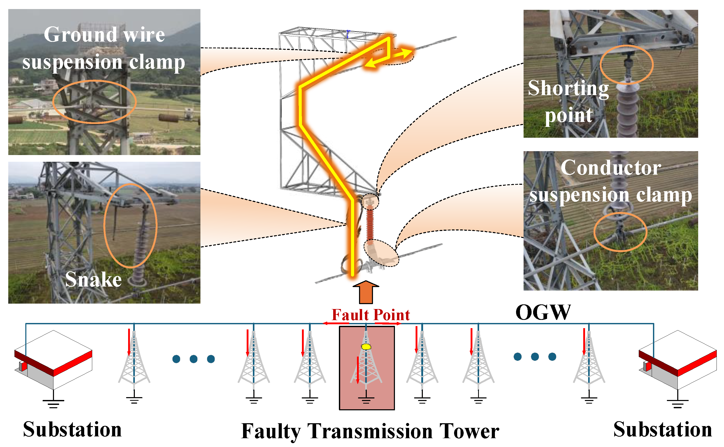
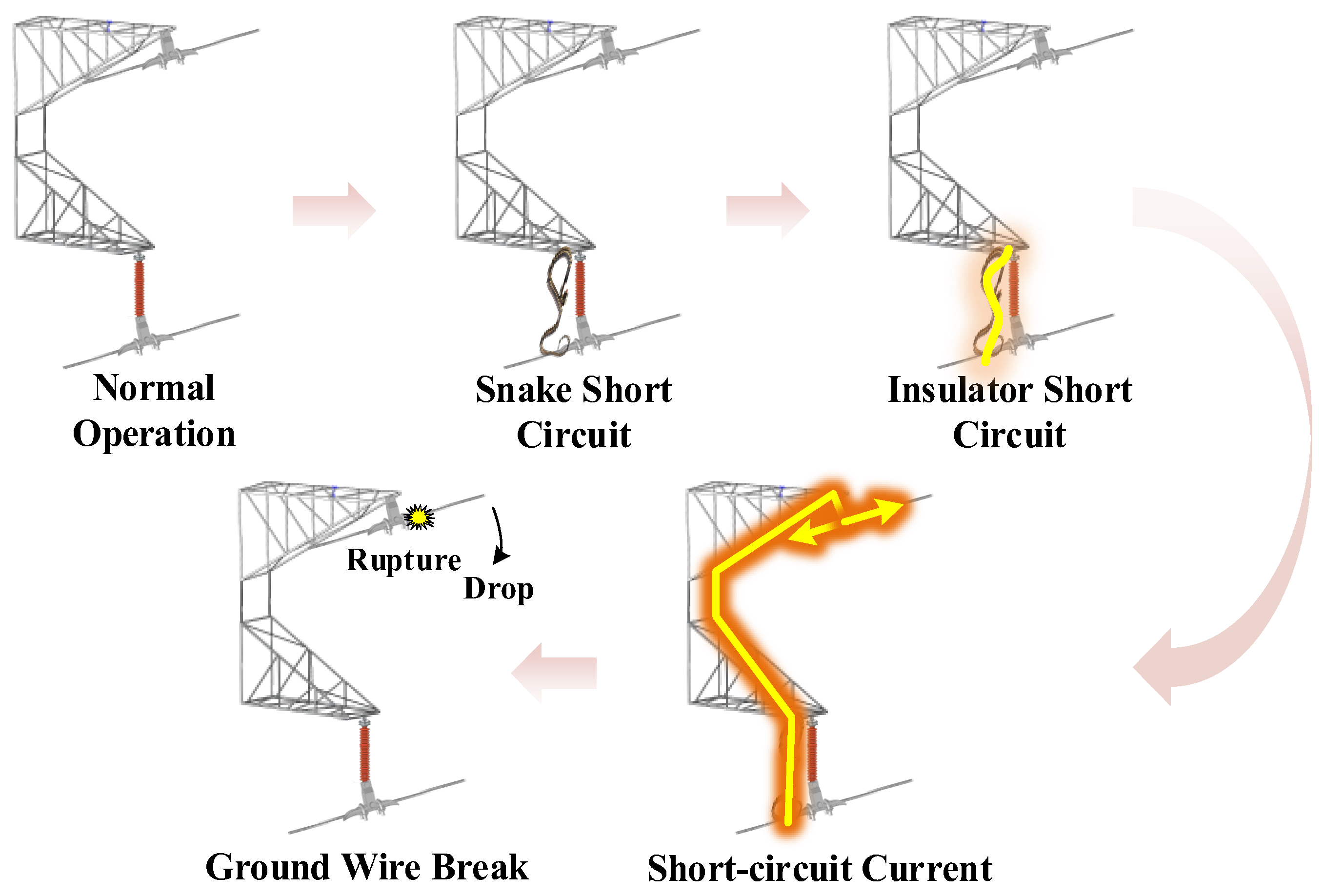
According to the investigation, the accident was caused by a single-phase short circuit triggered by a snake crossing between the B-phase power line and the crossarm. The snake was about 2.3 m long. There are obvious discharge traces on the crossarm of Phase B (upper phase), both end sheds and grading rings of the insulator, and the OGW. The right OGW has broken and fallen off at the suspension clamp position. From the line wiring method, it can be seen that during the short-circuit accident, the short-circuit current flowed through the suspension clamp on the top of the tower, entered the OGW, and then diverged toward the towers on both sides. Among them, part of the short-circuit current flowed into the ground connected to each tower along the way, while the remaining current flowed into the substations on both sides. The schematic diagram of the accident scene is shown in Figure 1 below.
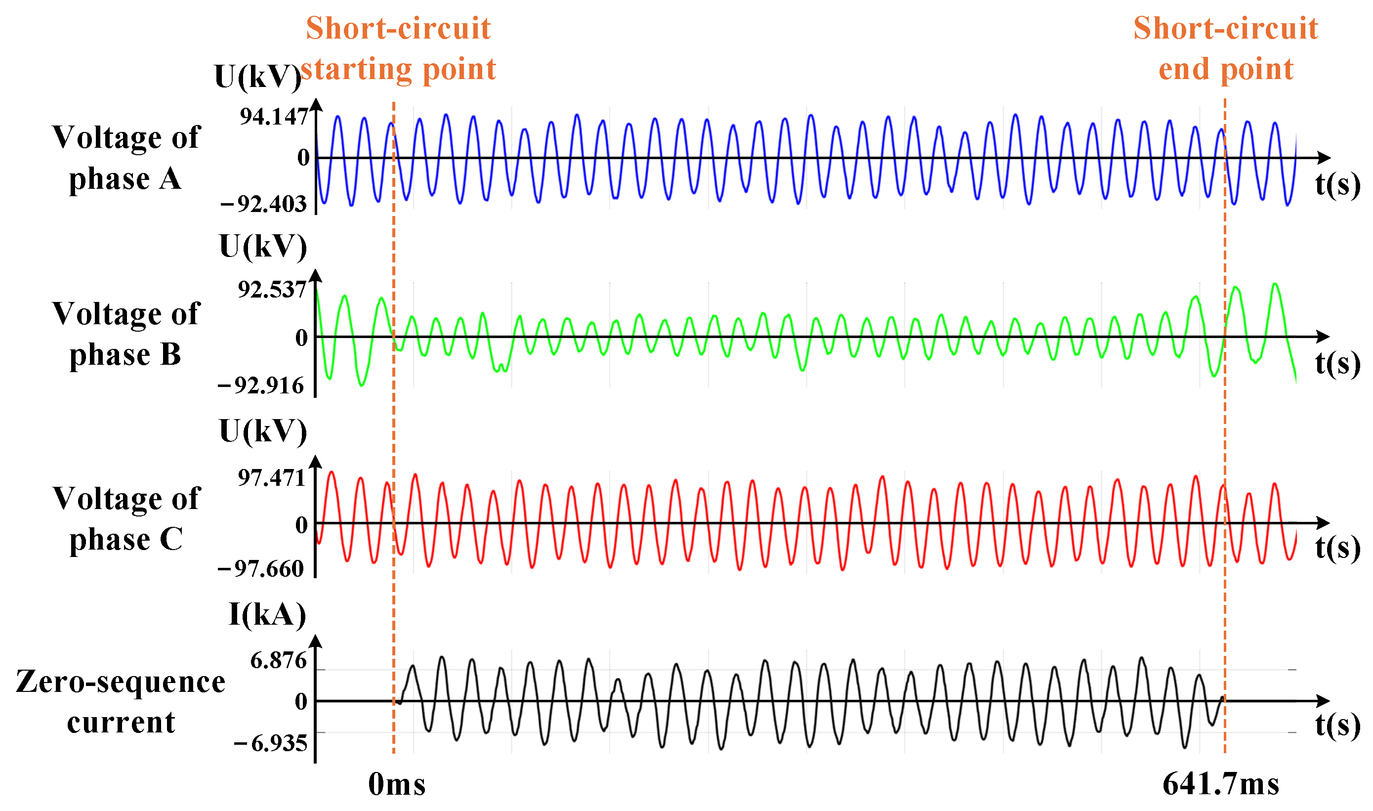
The model of the wave recording device is PCS-943A-N. Its sampling rate is 1200 Hz, with an effective bandwidth of approximately 0–550 Hz. According to the wave recording of the relay protection device, the amplitude of the short-circuit current is 6.9 kA, with a duration of 641.7 ms. The fault waveform recorded by the wave recording device is shown in Figure 2. Since the 110 kV system is a high-current grounded system, when a ground fault occurs on one phase, the phase voltage of the faulted phase will drop significantly. The phase voltages of the healthy phases remain basically unchanged. At the same time, a significantly increased zero-sequence current will appear in the system. This is consistent with the characteristics reflected in the fault-recording waveform.

2.2. Observation of Fracture Morphology

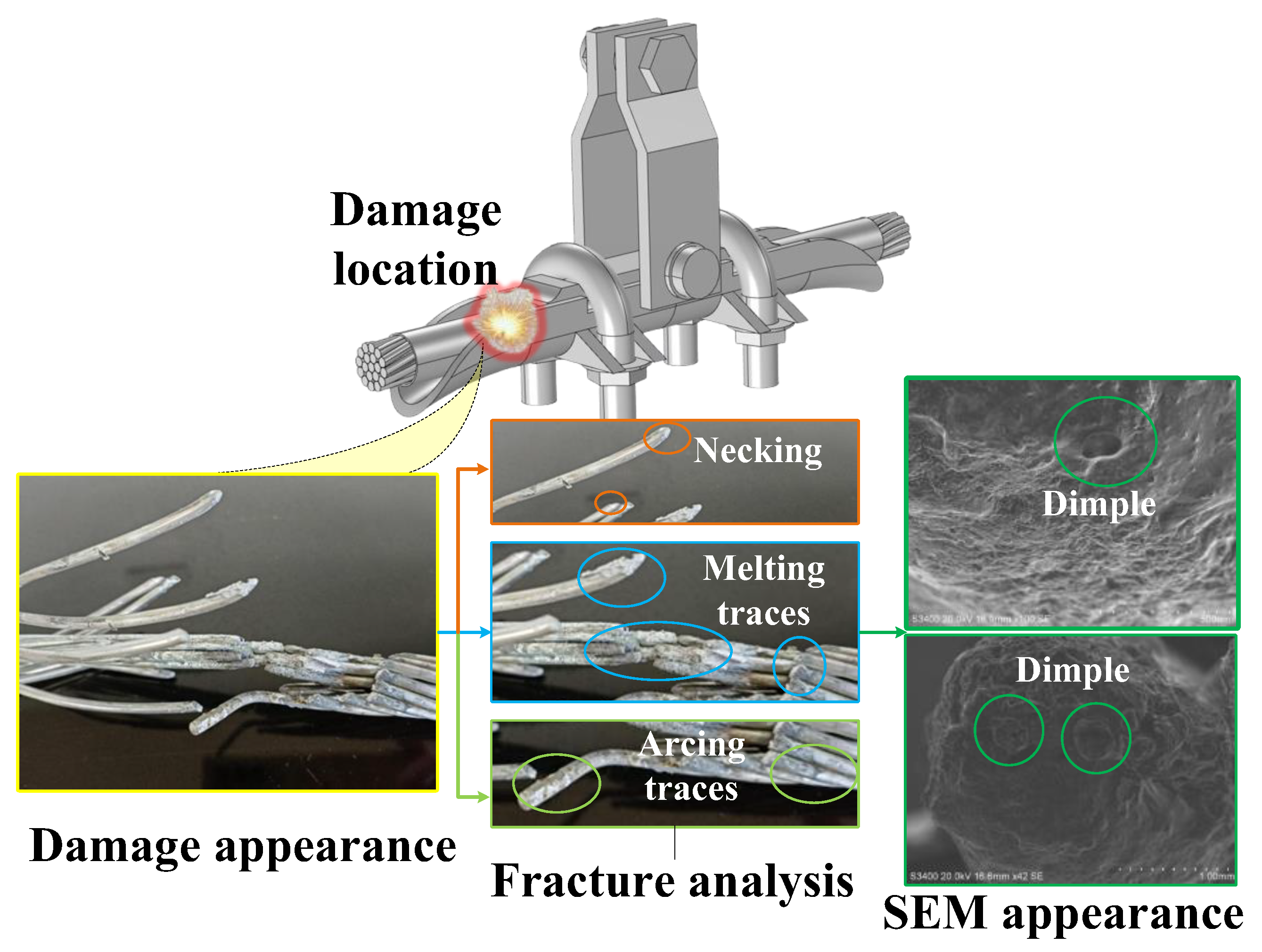
Observing the fracture of the OGW from a macroscopic perspective, distinct color boundaries can be seen on the surface of the OGW on both the left and right sides of the fracture. The distance between the left and right boundaries is approximately equal to the length of the suspension clamp or aluminum tape wrapping. The breakage point is located on one side of the suspension clamp. After dismantling the OGW, it was found that there were melting traces and arc burn traces on the surface of the OGW at the position of the fastening bolt of the suspension clamp pressing plate. Further investigation revealed that the steel core surface near the fracture was covered with a layer of melted material, and the steel core exhibited a pronounced necking phenomenon. The outer layer of the OGW consists of 12 strands of aluminum wires, among which 7 strands exhibit a dark gray fracture surface. The fracture of one aluminum wire exhibits a clear necking shape, indicating a tensile fracture. Two aluminum wires are bright in color, indicating a melting fracture. Two aluminum wires in the original sample have already fallen off and been lost. No obvious fatigue pattern fracture characteristics were observed on the OGW, thus ruling out the possibility of ground wire fatigue fracture caused by aeolian vibration.
Furthermore, this article conducts an SEM analysis of the fracture surface of the OGW. According to the SEM results, dimples are visible on some of the steel core fractures. This phenomenon indicates that before the fracture accident, the steel core had good plasticity and toughness, absorbing a large amount of energy during the fracture process. Observing the morphology of the dimples, it can be seen that the micro-pits are approximately circular, belonging to the equiaxed dimple type. Dimples of this shape suggest that the fracture was mainly caused by tensile stress. It is preliminarily speculated that the main cause of the OGW fracture was the local high temperature generated at the contact point between the OGW and the clamp when the short-circuit current flowed through them. The high temperature significantly reduced the tensile strength of the OGW, which ultimately could not withstand normal tension and fractured. The characteristics of the ground wire fracture are shown in Figure 3.
To gain a deeper understanding of the fracture, this article conducts an EDS analysis of the melted material at the fracture site. According to Table 2, the element with the highest content is oxygen, followed by aluminum, carbon, iron, and zinc, in descending order of content. From this, it can be inferred that the melted material primarily consists of oxides of aluminum, iron, and zinc, as well as unoxidized carbon in the iron core. This is consistent with the material composition of the OGW. Additionally, there are small amounts of potassium and phosphorus, which are present due to external environmental pollution or residuals from related process steps.

2.3. Summary of Accident

Based on the previous analysis, the development of this accident can be summarized as follows. Firstly, the snake short-circuited between the B-phase power line and the cross arm, causing a single-phase short-circuit accident. The short-circuit current flowed from the power line through the tower and into the OGW via the suspension clamp fixed at the top of the tower. Secondly, melting marks and arc burn marks were found on the surface of the OGW at the position of the suspension clamp’s fastening bolt. This phenomenon indicates that the OGW had experienced high temperatures. At the same time, the necking fracture surfaces of some steel cores and aluminum wires without melting material coverage, as well as the clearly visible equiaxed dimples under scanning electron microscopy, all suggest that the OGW ultimately fractured due to tensile stress. The lack of fatigue pattern fracture characteristics on the OGW rules out the possibility of fatigue fracture caused by aeolian vibration. From all the above analyses, this accident was caused by local high temperatures generated by the short-circuit current, which reduced the tensile strength of the OGW and ultimately led to ductile fracture. In summary, the development diagram of this accident is shown in Figure 4.
However, in addition to the thermal effect of current, the arc traces found at the scene of the accident indicate that a local arc was also generated during the short-circuit accident. Such discharge phenomena have not been observed in the laboratory so far. Is the thermal effect of current alone sufficient to cause the OGW to break? If there is a short-circuit arc, what is the proportion of the contribution of the arc heat source to the damage to the OGW? To answer the aforementioned questions, this article conducts a short-circuit impulse current experiment to reproduce the accident.

3. Short-Circuit Impulse Experiment

3.1. Experimental Design

To replicate the transient operating conditions encountered during the fault, this paper establishes a short-circuit impulse current test platform. The platform is designed to simulate the scenario where power-frequency short-circuit current flows through the OGW-suspension clamp assembly. Furthermore, a corresponding simulated discharge test scheme is developed. In this experiment, an impulse test transformer was utilized to apply an impulse current to the suspension clamp assembly, and optical and electrical signals during the discharge process were simultaneously collected.
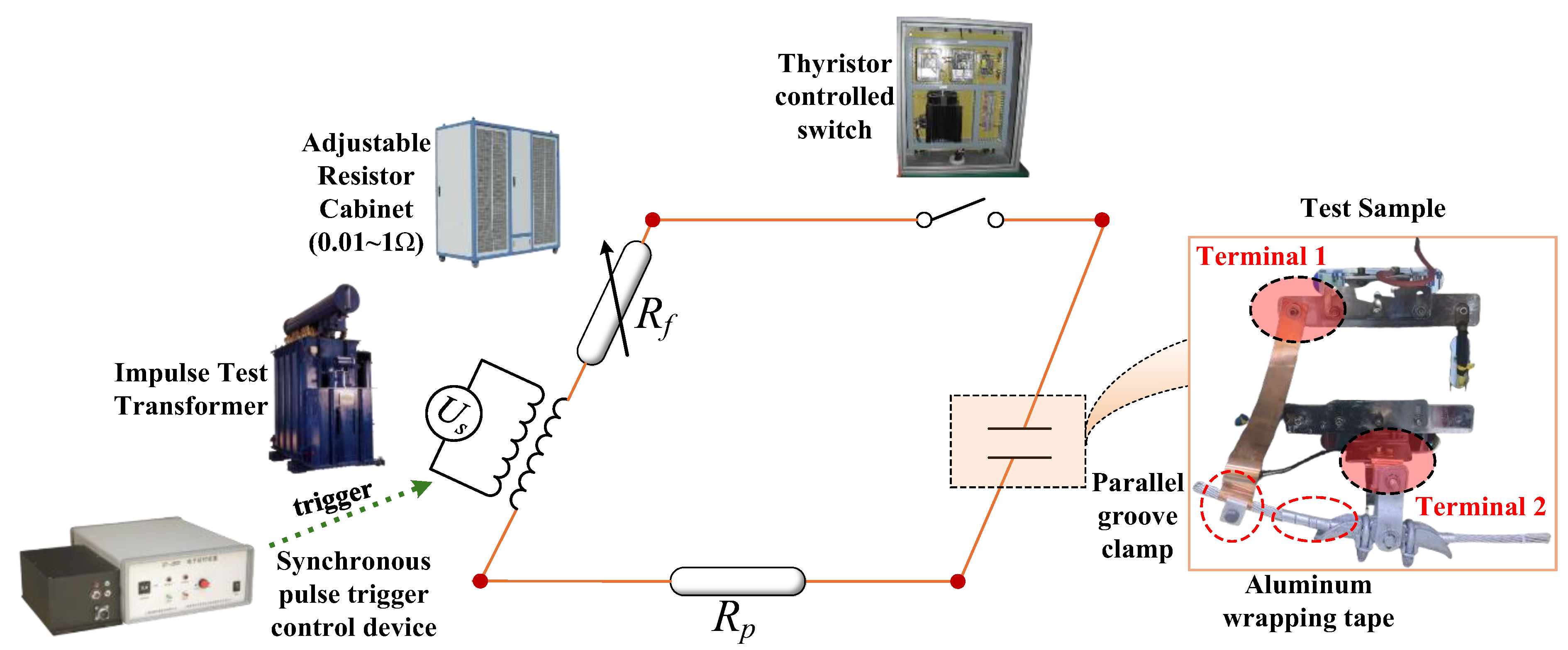
The test sample utilizes an LGJ-95/55 OGW and an XGU-3 suspension clamp, the same models as those used at the accident site, with the OGW having a length of approximately 50 cm. The surface of the OGW inside the clamp is wrapped with approximately 30 cm of aluminum tape. The experimental platform primarily consists of an impulse test transformer, an adjustable resistance cabinet, a thyristor control switch, a synchronous pulse trigger control device, current/voltage transformers, a high-speed camera system, and a main control unit. Due to the extremely high energy of short-circuit impact current, a high-current-carrying copper braided tape is used as the current-carrying wire and reliably connected to the OGW through a parallel groove clamp. The schematic diagram of the experimental platform structure is shown in Figure 5.
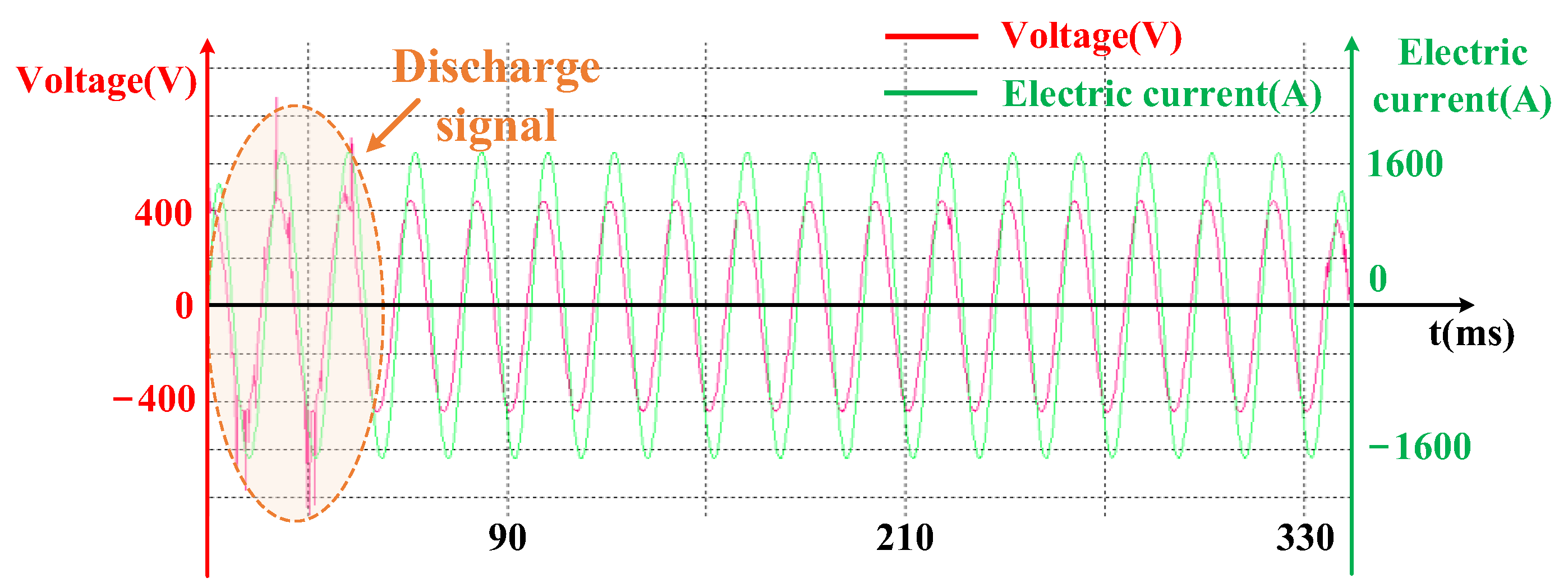
During the experiment, a high-speed camera system was employed to record the discharge phenomenon at the moment of short-circuit impact. The voltage and current waveforms during the impact process were simultaneously acquired through a current/voltage transformer measurement system. In actual accidents, the OGW-suspension clamp assembly withstands a power-frequency short-circuit current amplitude of approximately 6900 A, with a duration of about 640 ms. Due to the capacity limitation of the experimental equipment, the current amplitude applied in this simulation experiment is approximately 1600 A, with a duration of 360 ms. Table 3 lists the main characteristic parameters of the currents applied in the experiment.

3.2. Experimental Results and Analysis

Based on the short-circuit impulse current experimental platform, this paper attempts to replicate the operating conditions of the OGW-suspension clamp assembly when subjected to power-frequency short-circuit current. The experiment first generates power-frequency high voltage through an impulse test transformer. After the synchronous pulse trigger control device triggers the impulse test transformer to close, the current starts from the impulse test transformer and flows through a closed circuit of the impulse test transformer—adjustable resistance cabinet—terminal 1—copper braided tape—OGW—suspension clamp—terminal 2—protective resistor—impulse test transformer, achieving simulation of power-frequency short-circuit current during the accident.
During the experiment, the current and voltage waveforms collected by the current/voltage transformers are shown in Figure 6. As can be seen from Figure 6, at the moment of simulated power-frequency short-circuit current loading, the current waveform exhibits significant fluctuations, as indicated by the dashed box. Based on preliminary inference, the main reason for the fluctuation in the current waveform is the discharge phenomenon occurring in the OGW-suspension clamp assembly during the simulation of power-frequency short-circuit current loading. The discharge at the internal contact interface of the suspension clamp will cause variations in the total impedance of the entire experimental circuit, which in turn will lead to fluctuations in the circuit current.
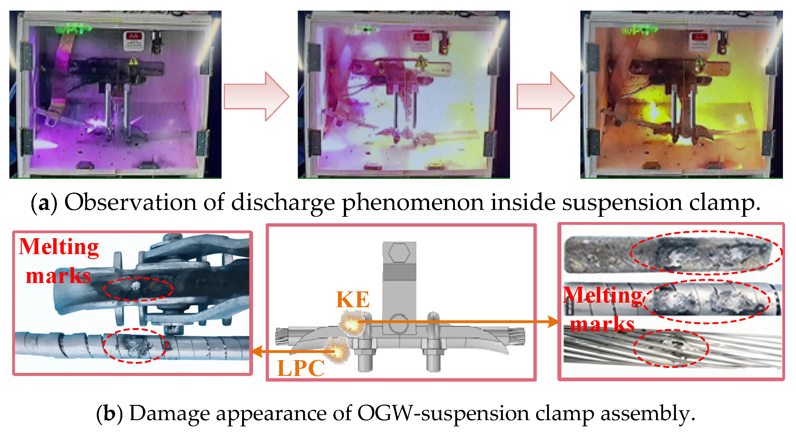
Figure 7 illustrates the experimental phenomena and sample damage appearance when a simulated power-frequency short-circuit current flows through the OGW-suspension clamp assembly. Specifically, (a) presents the optical imaging results, while (b) depicts the damage appearance. The experimental results indicate that under the influence of power-frequency short-circuit current, there is a severe discharge phenomenon occurring in the OGW-suspension clamp assembly. This further verifies the inferred reason for the current waveform fluctuation caused by the instantaneous loading of simulated power-frequency short-circuit current mentioned above. At the moment of loading with power-frequency short-circuit current, sparks flew from the suspension clamp position, and even a blue-purple arc was generated.
Furthermore, the internal damage of the OGW-suspension clamp assembly under short-circuit current conditions is analyzed. As can be seen from (b), the damage locations primarily occur at the LPC and KE of the suspension clamp. Two adjacent elliptical melting traces can be observed on the aluminum-clad tapes in both locations. There are black burn traces around them. If the aluminum tape wrapped around the OGW is removed, it can be clearly seen that there are obvious melt pits on the surface of the OGW. There are also clear black burn traces around the melt pits.
Through the aforementioned experiment, this chapter reproduced the discharge phenomenon within the earth wire-suspension clamp assembly when a power-frequency short-circuit current flows through it. Therefore, the discharge traces observed in Section 2.2 are indeed caused by arc discharge. Although this chapter confirms the existence of an electric arc, regarding this breakage accident, the following question remains: Which of the two heat sources—electric arc or Joule heating—is the dominant one? This issue still requires further exploration.

4. Simulation Study of OGW-Suspension Clamp Assembly Based on Multi-Field Coupling

4.1. Geometric Model and Material Settings

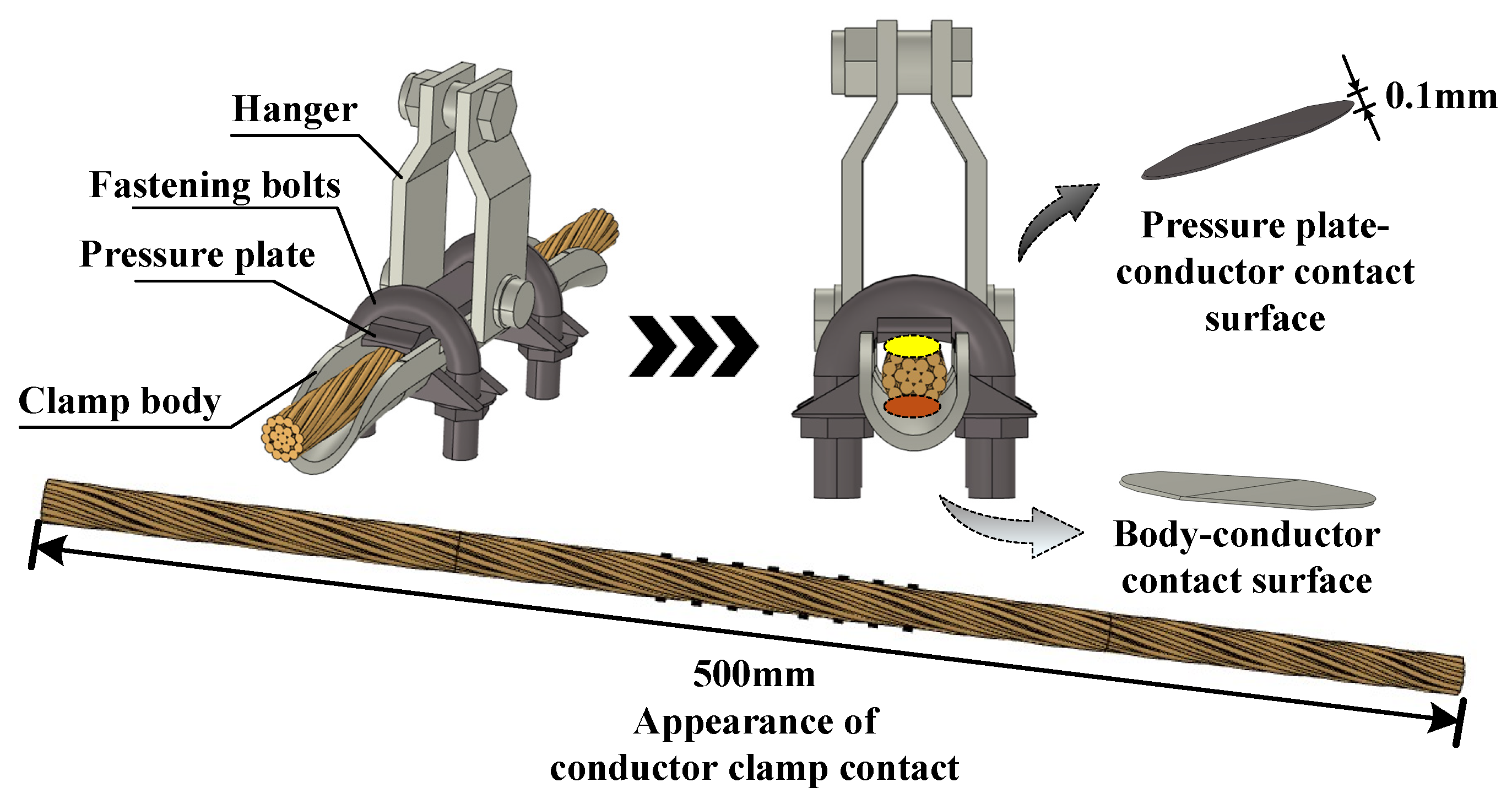
Based on COMSOL Multiphysics 6.3, a three-dimensional finite element model of the LGJ-95/55 OGW and XGU-3 suspension clamp assembly was established. The suspension clamp is primarily composed of the clamp body, pressure plate, hanger, and fastening bolts. In the model, the geometric shape of the aluminum cladding strip is neglected and replaced with an aluminum tube with a thickness of 1 mm for equivalence. The length of the OGW is set to 500 mm. According to the actual engineering specifications, the aluminum tape and the OGW at other locations are considered to be separated except for the contact pressure between the OGW and the aluminum tape at the clamp body and pressure plate. As a path for current flow, the equivalent treatment of contact points is crucial. Under the action of the fastening bolt, the suspension clamp pressure plate and the clamp body are pressed against the OGW wrapped with aluminum tape. Considering the uneven surface of the steel-cored aluminum strand, the actual contact interface presents oval-shaped contact points with equal spacing in both length and width [23]. Therefore, this paper adopts an elliptical cylindrical conductive bridge to simulate the actual contact point, with the height of the conductive bridge set at 0.1 mm [26]. In addition, the OGW-suspension clamp assembly is enclosed in an air space with dimensions of 500 × 60 × 120 mm. The geometric structure of the OGW-suspension clamp assembly is shown in Figure 8.
In practical engineering, LGJ-95/55 is a three-layer structure. The outer layer is made of aluminum strands, while the inner layer is a steel core. The suspension clamp is made of cast iron, while the aluminum-clad tape is made of aluminum. For the contact point, the conditions of elastic contact, contact deformation much smaller than the object size, and axisymmetric contact area are satisfied between the suspension clamp and the aluminum wire. Therefore, the outermost aluminum wire can be regarded as a sphere, and the suspension clamp as a plate, with the area of their contact points calculated using Hertz’s contact theory. The radius a of the contact surface on the pressure plate is shown in (1).
a = 3 F R 4 E 1 3
In this article, the radius of the aluminum wire is considered as the value of R , i.e., R = 1.6 × 10 3   m . The normal load force applied at each contact point on the pressure plate is:
F C , K = F K N = n 1 · T C K · d b · N
where n 1 is set as n 1 = 4 ; T C is set as T C = 80   N · m ; K is set as K = 0.2 ; d b is measured as d b = 16   m m ; and N is counted as N = 8 . The equivalent elastic modulus E is [27]:
1 E = 1 v 1 2 E 1 + 1 v 2 2 E 2
where E 1 = 70   G P a ; v 1 = 0.33 ; E 2 = 140   G P a ; and v 2 = 0.25 .
In research related to electrical contact, within the actual contact area between two objects (i.e., the contact patch), the area where actual conduction current flows is the only region where metals are in direct contact or where metals are in contact with a conductive surface film, known as the conductive patch. When current passes through a contact surface, it concentrates on flowing through extremely small conductive spots, which is equivalent to the “contraction” of current. As the effective conductive area decreases, local additional resistance, known as “contraction resistance,” [28,29] appears at the contact points. In the model, the contraction resistance R s of each contact point is obtained by:
R S = P f · ρ A l + ρ C a s t   i r o n 2 · π η H 4 F
where P f can be determined by the Williamson and Greenwood algorithm. P f ranges from 0.2 to 0.7, and here we take P f = 0.5 ; ρ A l = 2.65 × 10 8   Ω · m ; and ρ C a s t   i r o n = 1.67 × 10 7   Ω · m . Based on experience, the value of η is set to η = 6 % . Based on Holm’s definition of contact surface area [30], the following formula can be derived:
π a 2 = F H
From the defined formula of conductivity, we can derive:
σ = 1 ρ = l S R s
where l is also the height of the conductive bridge.
Since the elastic modulus of cast iron is approximately twice that of aluminum, the constant pressure heat capacity and thermal conductivity of the conductive bridge are considered to be approximately the same as those of cast iron. Table 4 presents the physical parameters of various materials in the model.

4.2. Boundary Condition Settings

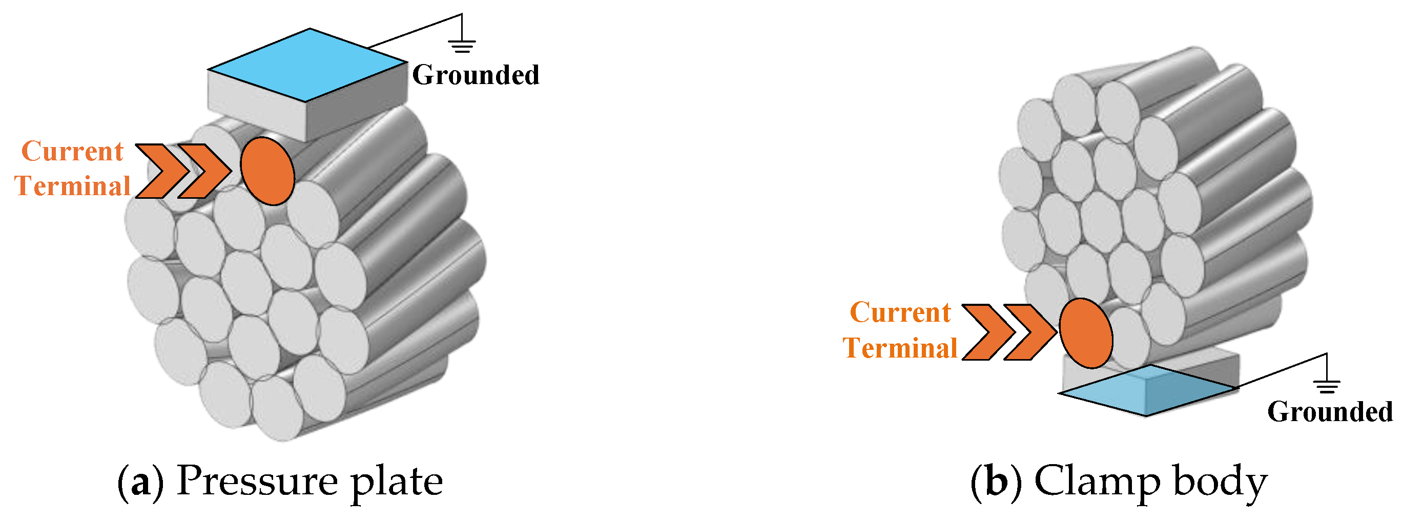
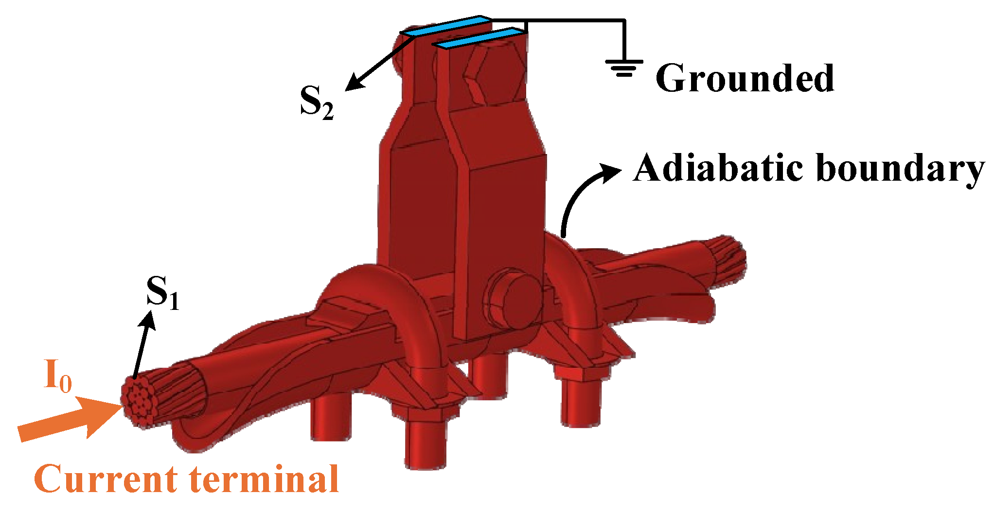
In the simulation model, it is necessary to set the boundary conditions for both the electromagnetic field and the temperature field separately. For different physical fields, this article explains the boundary condition settings of the simulation model with reference to Figure 9.
In the electromagnetic field, based on the current flow path in the actual OGW-suspension clamp assembly, one side end surface of the OGW is set as the current terminal. The upper end surface of the suspension clamp hanger is set as the grounding terminal. Based on the short-circuit current data collected at the accident scene, a power-frequency short-circuit current with an amplitude of 6.9 kA and a duration of 640 ms is applied to the model. The other surfaces of the model are set to be electrically insulated.
For the temperature field, due to the fact that the effect of the power-frequency short-circuit current lasts only 640 ms, heat is difficult to dissipate in such a short time. So, the heat exchange between the OGW and the external air can be neglected. In the simulation model, the surface of the OGW-suspension clamp model is set as an adiabatic boundary, and the adiabatic boundary condition equation is shown in (7).
n · q = 0
Based on the temperature on the day of the accident, the initial temperature of the model is set to 20 °C (equivalent to 293.15 K).

5. Simulation Results and Analysis

5.1. Electric Field Simulation Results and Analysis

To clarify the discharge mechanism inside the suspension clamp, this paper first analyzes the electric field strength at the contact interface. This is because the discharge phenomenon inside the suspension clamp mainly depends on the electric field strength at the contact interface. Based on Maxwell’s equations, the electric field strength at each contact interface can be calculated from the current density at the interface. Given the complexity of this model structure, directly calculating the electric field at the contact points may result in significant errors due to insufficient grid resolution. Therefore, this article adopts a segmented calculation method: first, calculate the current density at each contact point, and then deduce the electric field strength at the corresponding location based on the current density. The system of equations for calculating current density and electric field intensity is shown in (8).
· J = Q J = σ + ε 0 ε r t J e E = V
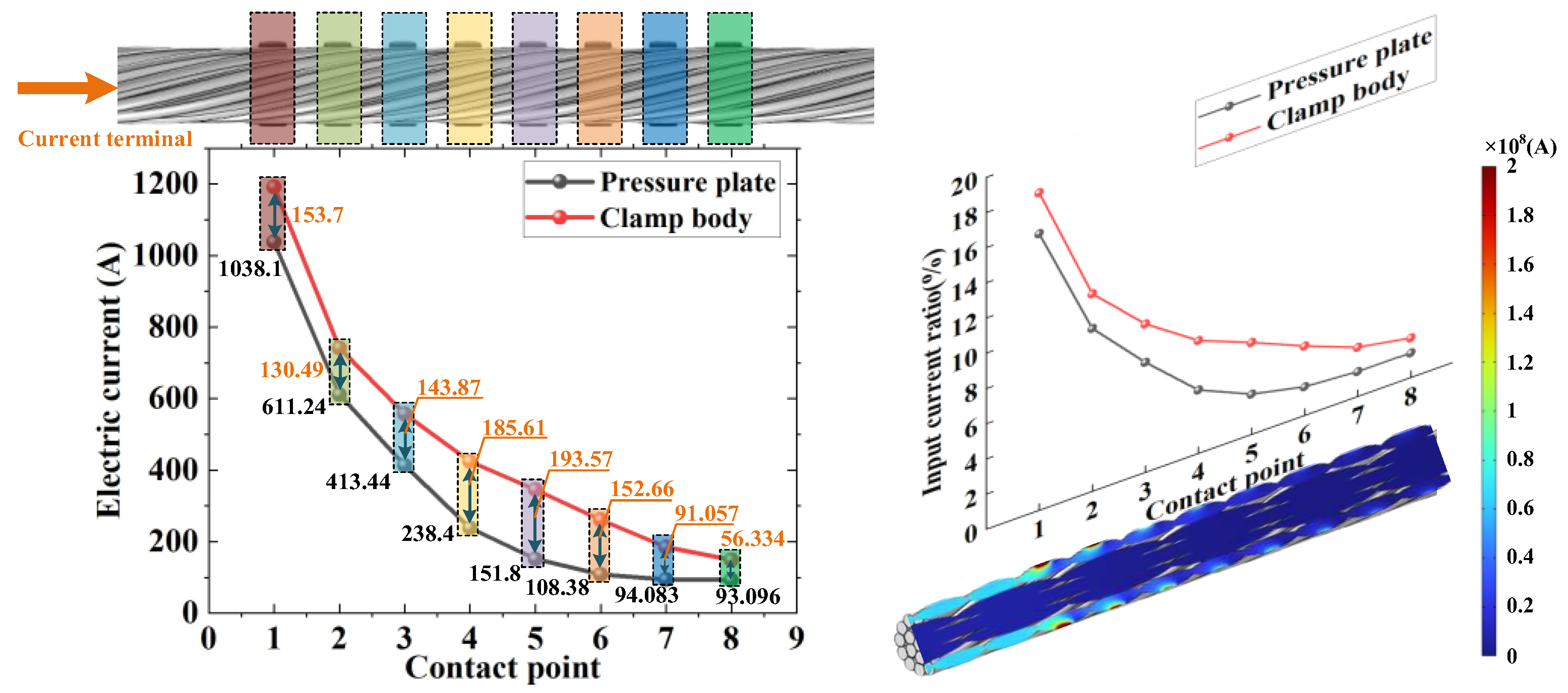
Simulate the electromagnetic field of the OGW-clamp assembly. The current distribution diagram at each contact point is shown in Figure 10. From the current distribution shown in Figure 10, it can be observed that the current is highly concentrated at the first contact point closest to the current input terminal, regardless of whether it is on the pressure plate or the clamp body. For the contact point of the pressure plate, the current flowing through it attenuates in two stages as the distance from the input terminal increases: it decreases sharply at first, and then tends to level off. The current variation at the clamp body contact point is similar to that of the pressure plate. At the same axial position, the current value at the clamp body contact point is always higher than that at the pressure plate contact point. The difference between the two decreases along the electric current path, then increases, and finally decreases again. The aforementioned distribution characteristics indicate that during an actual short-circuit process, the first contact point between the pressure plate and the clamp body bears the majority of the current. The high concentration of current at these locations may be a significant factor leading to severe discharge inside the clamp.
Based on the aforementioned model, aluminum tape is cut separately at the first contact point between the pressure plate, the clamp body and the OGW. Most of the surrounding aluminum tape is cut off to obtain a local single contact point model of the OGW-aluminum cladding tape. The end face of the wire strand that comes into contact with the aluminum cladding tape is selected as the excitation end. The surface of the aluminum cladding strip is set as a ground terminal. The electromagnetic field boundary conditions for the OGW-aluminum tape local single-contact-point model are set as shown in Figure 11.
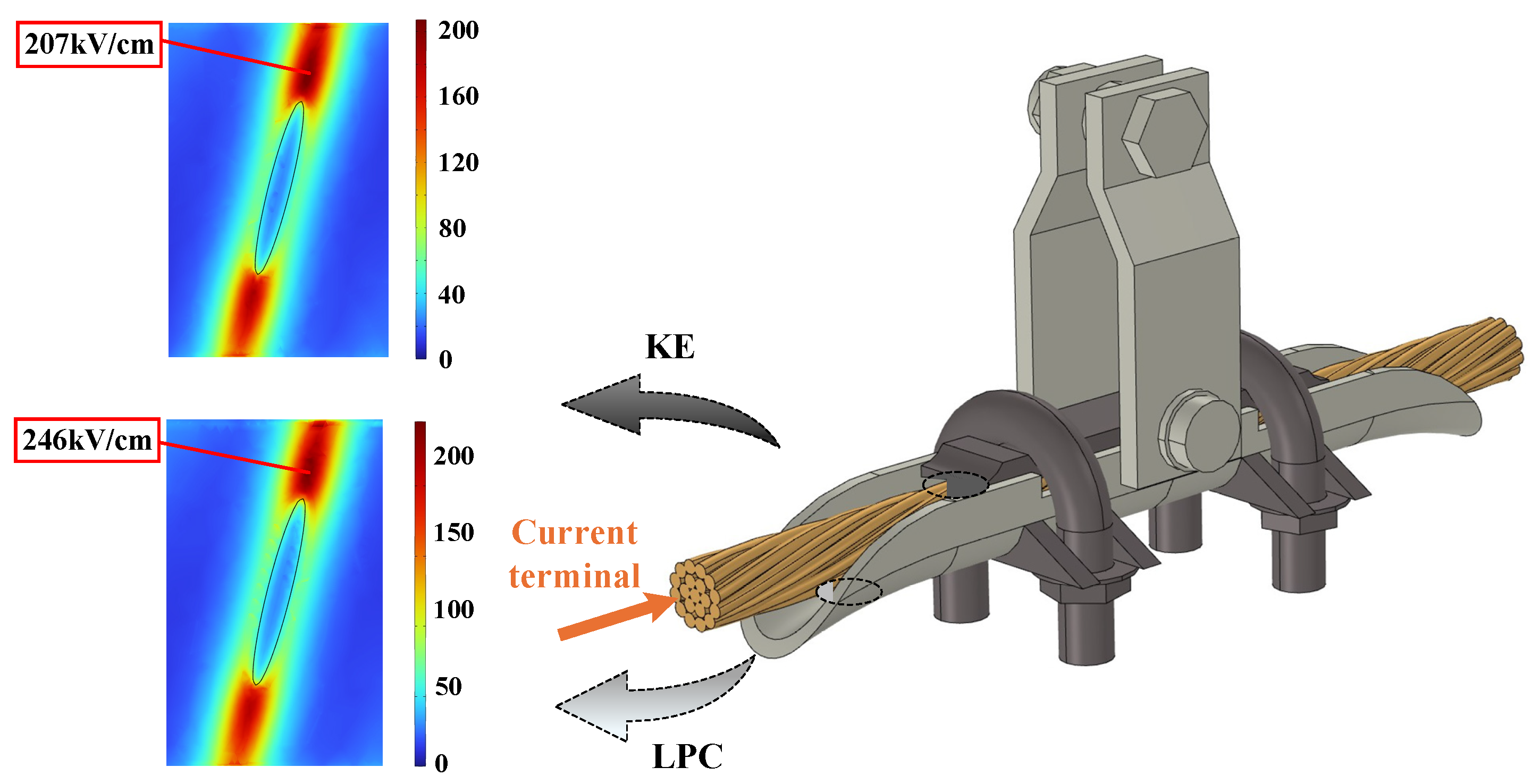
The current at the contact points is obtained through the integration of current density. The currents at the contact points on the pressure plate and the clamp body are 1038.1 A and 1191.8 A, respectively. Using this as input, the maximum electric field strength in the air gap near the contact point is analyzed and shown in Figure 12.
Observing the above figure, it can be seen that the location of the point with the maximum electric field intensity is in the air gap near the contact point. The maximum field strength at the contact point of the pressure plate is 207 kV/cm, and at the clamp body it is 246 kV/cm, both of which are much higher than the air breakdown field strength. Under normal atmospheric pressure, the classical Townsend gas discharge theory indicates that the critical breakdown electric field strength is approximately 30 kV/cm. In the model presented in this paper, the discharge gap is small and not a regular interelectrode discharge, constituting an extremely non-uniform field. Therefore, the actual critical breakdown electric field strength under these conditions would only be smaller, and the value used in the manuscript is already highly conservative. The electric field intensity in the air gap near the end of the long axis of the elliptical contact point is much higher than in other areas, with a maximum field intensity point, making it more prone to discharge breakdown. In practical conditions, due to the presence of an oxide film and shrinkage effect between the OGW and the aluminum tape, the actual contact area between them is smaller. As a result, the maximum electric field strength near the long axis of the contact point in the air gap is greater, making it more prone to discharge phenomena.
Consider the aforementioned contact points as contact spots in the contraction effect. The long axis end of the elliptical contact point is pointed. Due to the contraction effect, the current converges significantly at the tip, and the electric field intensity near the tip in the air gap increases. The smaller the bolt torque, the smaller the area of the contact point. When current passes through a smaller contact spot, it intensifies the “contraction” on the conductive spot, leading to poor current flow.

5.2. Joule Heating Simulation Results and Analysis

In order to lay the foundation for the simulation of transient thermal characteristics of arc heat in the following text, this section only considers the Joule heating effect of short-circuit current for comparison. Based on the conditions set in 4.2 boundary condition settings, this paper simulates the transient temperature distribution of the OGW inside the suspension clamp, as shown in Figure 13.
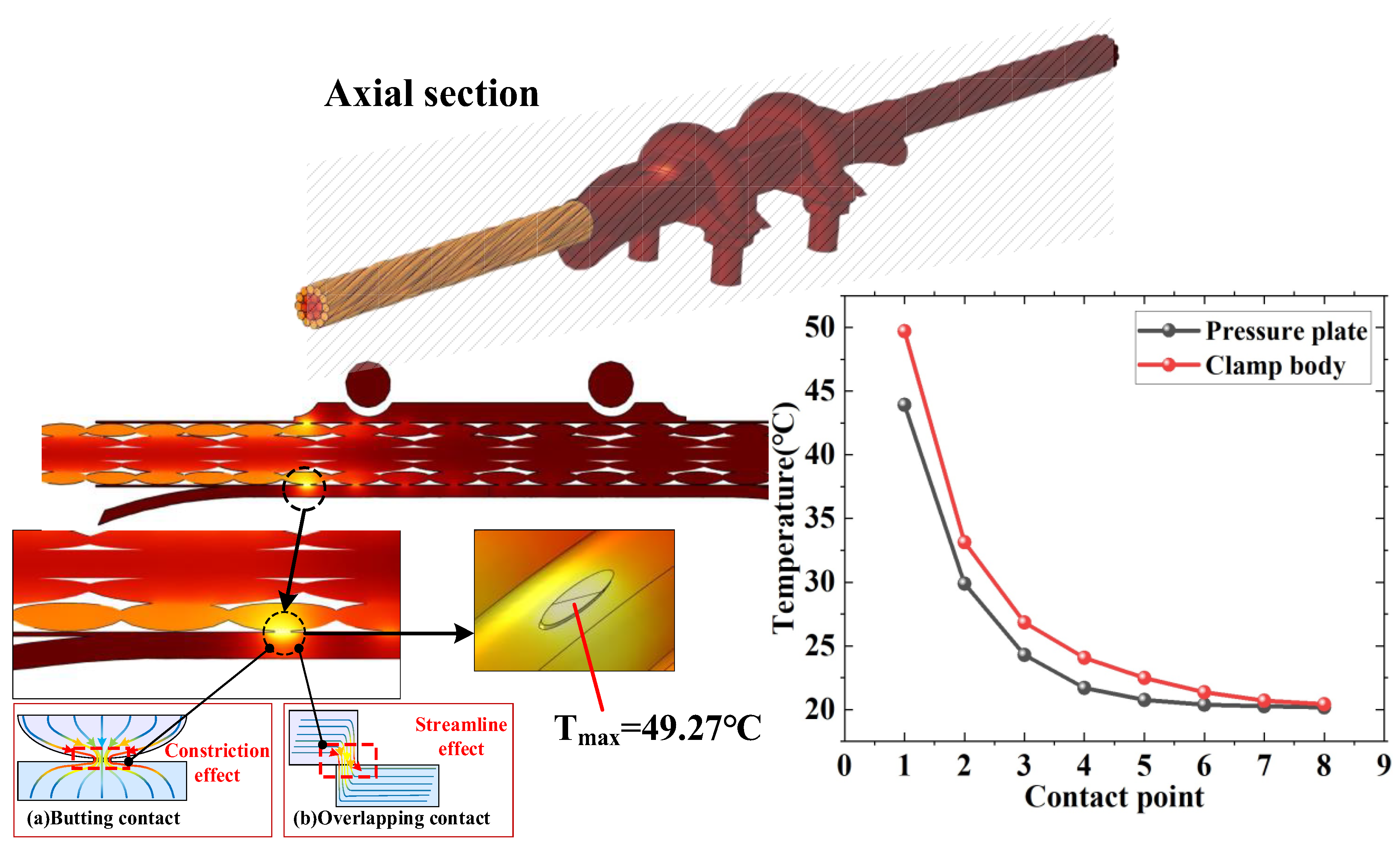
Observing Figure 13, it can be concluded that the Joule heat generated by the short-circuit current leads to a temperature rise in the contact area between the suspension clamp and the OGW, as well as in its adjacent areas. However, the simulation results indicate that the maximum temperature at each contact point is only 49.27 °C (occurring at the LPC point). Figure 13 also illustrates the temperature distribution at various contact points. It is evident that the high-temperature areas are concentrated at the LPC and KE points, with temperatures of 49.27 °C and 43.92 °C, respectively. Moreover, the temperature at the LPC and KE points rises sharply within the first 50 ms and then increases gradually.
The constriction effect occurs because the size of the contact point is much smaller than that of the OGW, causing the current lines to constrict on both sides of the contact point as the current flows through it. This constriction effect increases the additional resistance, known as constriction resistance. The streamlining effect arises because the cross-section of the contact point is elliptical, and simulations have shown that the current is not uniformly distributed on the elliptical contact surface but is concentrated at the ends of the major axis. From the elliptical geometry, it is evident that the ends of the major axis are narrower than other parts, which causes the actual area through which current flows to be much smaller than the apparent area, further exacerbating the constriction of current lines.
According to the current distribution diagram of each contact point in Figure 10, due to the higher current density at the LPC point, its temperature is slightly higher than that at the KE point. This is consistent with the relationship that Joule heat is proportional to the square of current. Except for the first two contact points between the pressure plate and the clamp body, the temperature rise at other contact points is relatively small (below 7 °C). Moreover, along the electric current path, the temperature rise becomes weaker the farther from the contact point at the input end. Overall, the temperature at the clamp body contact points is generally higher than that at the corresponding pressure plate contact points.
Comprehensive analysis indicates that the maximum temperature rise in the contact area during the short-circuit current action is only about 29.27 °C. Its temperature rises from an ambient temperature of 20 °C to 49.27 °C. This level of temperature rise is far below the melting threshold of aluminum (with a melting point of approximately 660 °C) or steel core materials (with a melting point of approximately 1450 °C). Therefore, the Joule heating effect alone cannot explain the melting and burning traces observed on the OGW in the accident. This further indicates that in this short-circuit fault, the high-temperature erosion caused by arc discharge is the primary mechanism leading to OGW damage, while the influence of the Joule heating effect is relatively limited. To analyze the contribution of arc thermal effects to OGW thermal damage, the arc is subsequently equivalent to a concentrated heat source acting on the air gap near the contact point. A transient heat transfer model is established to quantitatively calculate the temperature rise effect induced by the arc.

5.3. Simulation Results and Analysis of Transient Temperature Considering Arc Heat Transfer

According to the electric field simulation analysis results in Section 5.1, the electric field is significantly concentrated at the LPC contact point, where the electric field strength far exceeds the breakdown field strength of air (30 kV/cm). Therefore, discharge will preferentially occur at this location. In the modeling process, the air domain surrounding the LPC contact point is designated as the arc occurrence area, and a boundary heat source is employed to simulate the heat transfer process from the arc to the electrode surface. The model assumes that all arc energy is deposited on the material surface, and its spatial distribution is described using a Gaussian heat source, with the standard form shown in (9).
q r = 2 Q π R a r c 2 e r 2 2 σ G a u s s 2
Based on relevant research, the radius of the arc heat source typically ranges from 2.5 to 15 mm. Regarding the arc discharge caused by the tiny gap inside the on-line clamp of short-circuit current, this paper adopts R a r c = 5   mm [31]. The standard deviation σ G a u s s of the Gaussian distribution is defined as the radius corresponding to the point where the heat flux density drops to 5% of the central value. The conversion relationship between it and the characteristic radius R a r c is:
σ G a u s s = R a r c 2 ln 0.05
In (9), Q is calculated using (11):
Q = η a r c U a r c I
The parameter η a r c typically ranges from 0.5 to 0.8, as shown in (11). In this paper, we adopt η a r c = 0.7 [32]. U a r c typically ranges from 4 to 5 V [15]. In this article, we adopt a value of 4 V. I = 6.9 kA.
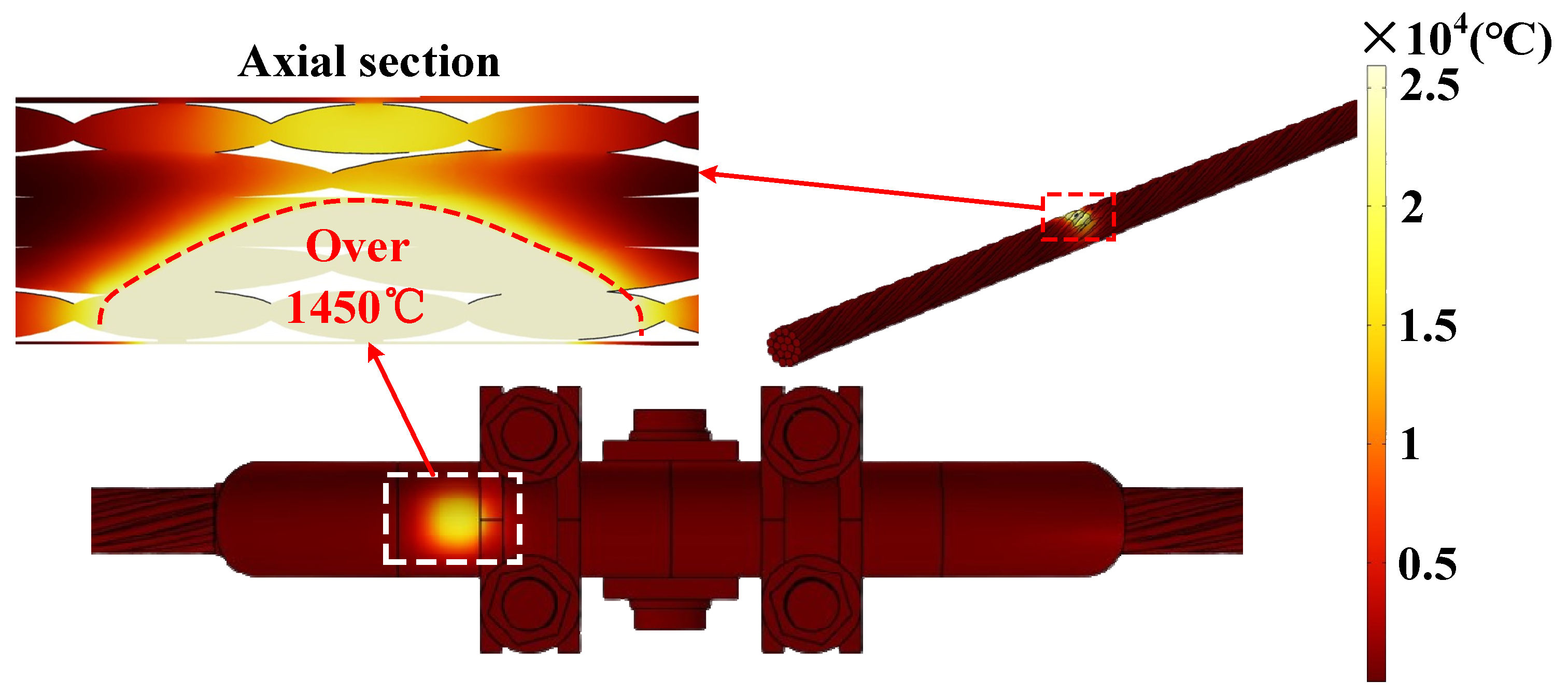
The aforementioned arc heat source was applied to the surface of the OGW and aluminum cladding strip near the LPC contact point, with a simulation time consistent with the duration of the short circuit (640 ms). This resulted in a transient temperature rise distribution of the OGW-suspension clamp assembly, taking into account arc heat transfer and Joule heating, as shown in Figure 14.
As can be seen from Figure 14, the temperature rise in the area affected by the arc heat source is extremely dramatic. During the duration of the short-circuit current, the maximum surface temperature of the aluminum strands near the LPC contact point exceeds the melting point of aluminum (660 °C) within milliseconds and can reach over 26,000 °C within 640 ms. It is noteworthy that this temperature is physically extreme and may be greatly sensitive to the model. The data source is simulation output under strongly simplified assumptions, rather than directly measured temperatures. This results in the rapid melting and vaporization of aluminum material, forming the melted pits observed in the simulation. The high temperature is simultaneously transmitted to the internal steel core, causing a significant increase in the temperature of the steel core, which can locally reach over 1450 °C, resulting in a sharp decrease in its tensile strength [17,19].
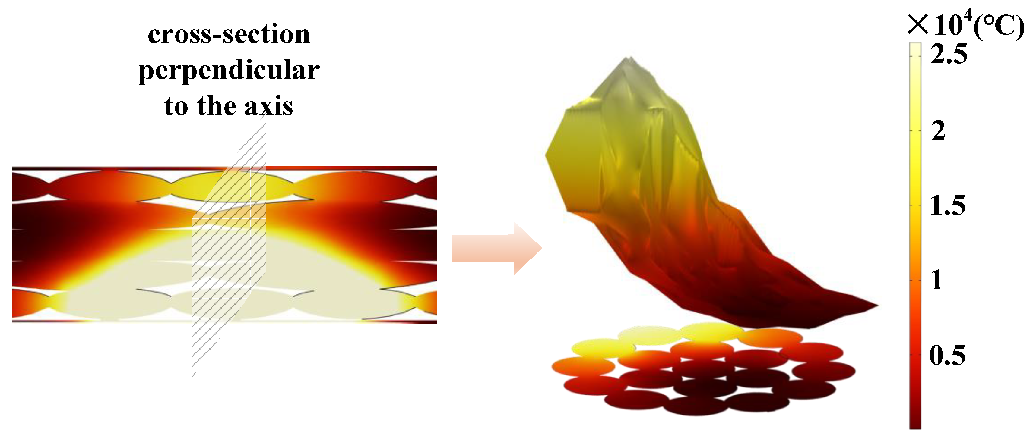
Due to the concentrated arc heat at the LPC contact point, which causes OGW strand breakage, this paper further analyzes the heat transfer perpendicular to the axis direction at this location. At the center of the LPC contact point, a transverse section perpendicular to the axis is taken from the OGW, obtaining the temperature rise distribution plane data of the OGW’s lateral heat transfer at the LPC contact point. The results are shown in Figure 15.
A three-dimensional temperature surface diagram perpendicular to the axis at the LPC contact point is plotted, using the temperature at each position as the height. The three-dimensional surface diagram shows that the highest temperature is concentrated in a small area near the LPC contact point. For other regions far from the LPC contact point, the temperature initially drops sharply and then gradually stabilizes as the distance from the contact point increases. As the distance from the arc heat-affected zone increases, the temperature at the corresponding position first drops sharply and then gradually declines.

6. Conclusions

This study investigates the fracture mechanism of a 110 kV OGW at a suspension clamp caused by a short-circuit fault, through combined experimental observation and multi-physics numerical simulation. The following conclusions are drawn:
(1)
When short-circuit current flows through the OGW-suspension clamp assembly, intense arc discharge occurs preferentially at the LPC and KE contact points. The electric field intensity at these locations reaches 246 kV/cm and 207 kV/cm, far exceeding the air breakdown strength, confirming the inevitability of discharge under the tested conditions.
(2)
Joule heating alone raises the local temperature to only 49.27 °C, which is far below the melting points of both aluminum (660 °C) and steel (1450 °C). Therefore, Joule heating is insufficient to cause any significant thermal damage to the OGW.
(3)
In contrast, arc heating elevates the local temperature above 26,000 °C within milliseconds, causing rapid melting of aluminum strands and heating of the steel core above 1450 °C. This extreme thermal exposure results in a sudden reduction in the effective load-bearing cross-section and tensile strength, ultimately leading to ductile fracture under normal operating tension.
(4)
This study provides the first direct experimental evidence of internal arc discharge in suspension clamps under short-circuit conditions and quantitatively demonstrates that arc heat, rather than Joule heat, is the decisive factor in OGW fracture accidents.
(5)
The findings offer a more accurate theoretical basis for fault protection and hardware design optimization of overhead transmission lines, particularly in terms of improving contact interface design and verifying bolt pre-tightening forces during routine maintenance.
(6)
Limitations of this study include the simplified Gaussian arc heat source model and the focus on a single accident case. Future research should develop more sophisticated arc models incorporating plasma dynamics and radiative transfer, investigate their generalizability to different current levels and durations, and establish an integrated thermo-mechanical framework to simulate the complete failure process from thermal exposure to mechanical fracture.

Author Contributions

Software, J.C.; Data curation, J.C.; Writing—Original Draft Preparation, J.C.; Writing—Review and Editing, X.Z.; Supervision, X.Z.; Funding Acquisition, X.Z. All authors have read and agreed to the published version of the manuscript.

Funding

This research was funded by South China University of Technology, grant number GDDKY2024KF10, 2024M760942, 2025A1515010291. And The APC was funded by GDDKY2024KF10, 2024M760942, 2025A1515010291.

Data Availability Statement

The original contributions presented in this study are included in the article. Further inquiries can be directed to the corresponding author.

Acknowledgments

The authors gratefully acknowledge the support of the Guangdong Electric Power Equipment Reliability Key Laboratory Open Fund, South China University of Technology (Grant/Award Number: GDDKY2024KF10); the China Postdoctoral Science Foundation, South China University of Technology (Grant/Award Number: 2024M760942); and the Guangdong Basic and Applied Basic Research Fund General Project, South China University of Technology (Grant/Award Number: 2025A1515010291).

Conflicts of Interest

The authors declare no conflicts of interest.

Nomenclature

AbbreviationFull Form
OGWOverhead ground wire
LPCLower-pressure-plate contact point
KEKeeper-edge contact point
SEMScanning electron microscopy
EDSEnergy-dispersive spectroscopy
SymbolDescriptionUnit
a Radius of contact surfacem
d b Nominal diameter of boltm
E Electric field strength V · m 1
E Equivalent elastic modulusPa
E 1 , E 2 Elastic modulus of aluminum, cast ironPa
F Normal force at each contact pointN
F C , K Normal load force at pressure plate/clamp body contactN
H Hardness of contact surface materialPa
I Short-circuit current amplitudeA
J Current density A · m 2
J e External current density A · m 2
K Thread factor
l Length of the resistor
N Number of contact points
n 1 Number of bolts
P f Plating factor
Q Total power of arc heat transferW
q ( r ) Heat   flux   density   at   distance   r from arc center W · m 2
R Radius of spherem
R a r c Characteristic radius of arc heat sourcem
R s Constriction resistance of a single contact point Ω
r Radial distance from heat source centerm
S Contact area of conductive bridge m 2
T C Nut torque N · m
t Times
U a r c Arc voltageV
V Electric potentialV
ε 0 Vacuum permittivity F · m 1
ε r Relative permittivity
η Contact area ratio
η a r c Efficiency coefficient of arc energy transfer
v 1 ,   v 2 Poisson’s ratio of aluminum, cast iron
ρ Electrical resistivity Ω · m
ρ A l ,   ρ C a s t   i r o n Resistivity of aluminum, cast iron Ω · m
σ Electrical conductivity S · m 1
σ G a u s s Standard deviation of Gaussian heat source distributionm

References

  1. Qin, B.; Wang, H.; Liu, G. Challenges and opportunities for long-distance renewable energy transmission in China. Renew. Sustain. Energy Rev. 2024, 199, 114545. [Google Scholar]
  2. Gallo Caicedo, R.A.; Bastianel, G.; Ergun, H.; Van Hertem, D. Reviewing high voltage transmission technologies for future transmission grids. In Proceedings of the 2025 AEIT HVDC International Conference (AEIT HVDC); IEEE: New York, NY, USA, 2025. [Google Scholar]
  3. Chen, H.; Wang, L.; Li, Z. Capacity assessment for wind-storage integration system considering electro-thermal coupling of overhead transmission line. IEEE Trans. Power Syst. 2023, 38, 3456–3467. [Google Scholar]
  4. Sakib, S.; Zamee, M.A.; Hossain, M.J.; Hossain, B.; Habib, A. Strengthening renewable-rich weak grids through improved voltage stability and fault-ride through capability. IET Renew. Power Gener. 2026, 20, e70188. [Google Scholar] [CrossRef] [Scilit]
  5. Essaddi, N.; Saidani, K.; Besbes, M. Overcoming the integration bottleneck: A global review of renewable energy and grid adaptation strategies. Int. J. Sustain. Energy 2025, 44, 2569922. [Google Scholar] [CrossRef] [Scilit]
  6. Fan, X. Grid integration of renewable energy and energy storage. In Proceedings of the 2024 IEEE 52nd Photovoltaic Specialist Conference (PVSC); IEEE: New York, NY, USA, 2024; pp. 1532–1534. [Google Scholar]
  7. Zhao, H.; Zhen, Y.; Zhu, Y.; Wang, N.; Fan, M.; Wang, H. Ultra-Long Distance Sensing and Deep Learning-Based Condition Assessment Method for Power Transmission Lines. In Proceedings of the 2025 10th Asia Conference on Power and Electrical Engineering (ACPEE), Beijing, China, 15–19 April 2025; pp. 547–551. [Google Scholar]
  8. Wang, S.; Chen, H.; Dai, F.; Wu, Q.; Yang, X.; Bo, X. Research on LoRa based State Sensing Technology for Overhead Lines. In Proceedings of the 2023 International Conference on Intelligent Computing, Communication & Convergence (ICI3C), Bhubaneswar, India, 16–17 December 2023; pp. 510–515. [Google Scholar]
  9. Nan, L.; Wulue, Z.; Wenjun, Y.; Xin, Z.; Daxuan, C.; Kai, L. Application of Beidou technology in infrastructure acceptance of overhead transmission lines. In Proceedings of the 2023 2nd International Conference for Innovation in Technology (INOCON), Bangalore, India, 3–5 March 2023; pp. 1–5. [Google Scholar]
  10. Levacic, G.; Bozicek, A.; Filipovic-Grici, B.; Franc, B.; Mesic, K.; Grebenar, F.; Jurisic, B.; Ivankovic, I. Effects of Extreme Weather Events on Croatian Power Transmission Network. In Proceedings of the 2025 IEEE Power & Energy Society General Meeting (PESGM), Austin, TX, USA, 27–31 July 2025; pp. 1–5. [Google Scholar]
  11. Atat, R.; Shaaban, M.F.; Ismail, M.; Serpedin, E. Efficient unmanned aerial vehicle paths design for post-disaster damage assessment of overhead transmission lines. IET Smart Grid 2023, 6, 503–521. [Google Scholar] [CrossRef] [Scilit]
  12. Ma, P.; Yang, Y.; Zhao, G.; He, Y.; Liang, P.; Li, B. Research on Damage Identification of Overhead Ground Wires in Cable Clips Based on ASTFA and Time-Frequency Entropy. In Proceedings of the 2023 Asia-Pacific Conference on Image Processing, Electronics and Computers (IPEC), Dalian, China, 14–16 April 2023; pp. 173–181. [Google Scholar]
  13. Li, X.; Yang, S.; Wu, Y.; Kong, T. Full-Scale Tests and Optimization Studies on Suspension Strings of the Ground Wire of UHVDC Transmission Lines. In Proceedings of the 2023 International Conference on Electronics and Devices, Computational Science (ICEDCS), Marseille, France, 22–24 September 2023; pp. 486–490. [Google Scholar]
  14. Chen, Q.; Li, H.; Xiong, Z.; Cheng, S.; Wang, R.; Xia, M.; Qi, G.; Lin, J.; Huang, B.; Liu, G. Identification of the Ground Wire-Suspension Clamp Damage Under the Effect of Lightning Current. In Proceedings of the 2023 IEEE 7th Conference on Energy Internet and Energy System Integration (EI2), Hangzhou, China, 15–18 December 2023; pp. 3959–3964. [Google Scholar]
  15. Wei, P.; Zhang, Z. Study on Measures to Improve the Short-Circuit Thermal Stability of OPGW. In Proceedings of the 2022 IEEE 6th Conference on Energy Internet and Energy System Integration (EI2), Chengdu, China, 28–30 October 2022; pp. 1109–1113. [Google Scholar]
  16. Zheng, C.; Deng, G.; Huang, B.; Wang, R.; Guo, D.; Liu, G. Vibration-induced micro-discharge at suspension clamp-conductor interfaces under short circuit conditions. Electr. Power Syst. Res. 2026, 255, 112772. [Google Scholar] [CrossRef] [Scilit]
  17. Li, H.; Cheng, L.; Huang, B.; Cheng, S.; Lin, J.; Nie, W.; Guo, D.; Liu, G. Electrothermal damage numerical analysis for overhead ground wire at terminal of armor rods under short-circuit current. Electr. Eng. 2025, 107, 4313–4323. [Google Scholar]
  18. Liu, G.; Zheng, W.; Guo, D.; Peng, R.; Lin, X.; Zhong, M. Numerical modeling and analysis of thermal and mechanical behavior for ground wire–clamp system under short-circuit current. Electr. Power Syst. Res. 2021, 199, 107497. [Google Scholar] [CrossRef] [Scilit]
  19. Huang, B.; Liu, G.; Wang, R.; Lin, X.; Chen, S.; Guo, D. Analysis of the discharge phenomenon inside the suspension clamp based on an overhead ground wire breakage case. Electr. Power Syst. Res. 2025, 241, 111384. [Google Scholar] [CrossRef] [Scilit]
  20. Ashfaq, A.; Khalique, U.; Nadeem, A.; Rizvi, A.A. Comprehensive analysis of temperature distribution in OPGW cable considering ramifications of short circuit current. Sci. Rep. 2025, 15, 21949. [Google Scholar] [CrossRef] [Scilit] [PubMed]
  21. Liu, D.; Zheng, H.; Huang, K.; Lian, J.; Guo, D.; Liu, G. Study of overhead grounding wire and preformed armor rods port based on multi-physical field coupling. In Proceedings of the 2023 6th International Conference on Renewable Energy and Power Engineering (REPE), Beijing, China, 15–17 September 2023; pp. 180–185. [Google Scholar]
  22. Guo, D.; Liu, G.; Chen, H.; Wang, P.Q.; Lin, X. Influence of structural characteristics for overhead ground wire on arc root under lightning strike. Electr. Eng. 2023, 105, 3283–3292. [Google Scholar] [CrossRef] [Scilit]
  23. Lu, J.; Liu, X.; Shi, Z.; Zeng, Y.; Luo, Y. Numerical Analysis of Terminal of Armor Rods for Ground Wire Based on Electromagnetic-Thermal-Structural Coupling under the Short-Circuit Current. In Proceedings of the 2022 12th International Conference on Power and Energy Systems (ICPES), Guangzhou, China, 23–25 December 2022; pp. 140–146. [Google Scholar]
  24. Li, H.; Chen, Q.; Cheng, S.; Dong, Z.; Wang, R.; Cai, R.; Huang, B.; Liu, G. Discharge Conditions Analysis of Lightning Current Action on Ground Wire-Suspension Clamp System. In Proceedings of the 2023 6th International Conference on Energy, Electrical and Power Engineering (CEEPE), Guangzhou, China, 12–14 May 2023; pp. 220–224. [Google Scholar]
  25. Deng, H.; Peng, R.; Zhong, M.; Yang, R.; Liang, Y.; Guo, D.; Liu, G. A case study of rupture in overhead ground wire twined by armor rod. Eng. Fail. Anal. 2022, 131, 105844. [Google Scholar] [CrossRef] [Scilit]
  26. Li, H.; Chen, Q.; Wang, J.; Cheng, S.; Nie, W.; Xia, M.; Guan, W.; Huang, Z.; Huang, B.; Liu, G. The Effect of Conductive Bridge Shape on the Electrothermal Simulation Results of Ground Wire-Suspension Clamp Assembly. In Proceedings of the 2023 3rd International Conference on Electrical Engineering and Mechatronics Technology (ICEEMT), Nanjing, China, 21–23 July 2023; pp. 173–177. [Google Scholar]
  27. Li, Y.; Ke, L.; Dong, X.; Chang, G.; Shen, F. Electrical Contact Resistance Between Rough Spherical Surfaces: Theory and Simulation. J. Tribol.-Trans. ASME 2026, 148, 041501. [Google Scholar]
  28. Li, Y.; Ke, L.; Chang, G.; Güler, M.A.; Shen, F. On the electrical contact resistance model of rough surfaces based on multi-physics modeling. Int. J. Solids Struct. 2025, 312, 113284. [Google Scholar]
  29. Khrestin, A.V.; Pavleino, M.A.; Safonov, M.S. Changing the characteristics of contact spots when short-circuit currents flow through closed high-current electrical contacts. Tech. Phys. 2024, 69, 1213–1221. [Google Scholar] [CrossRef] [Scilit]
  30. Holm, R. Calculation of constriction resistances with constant resistivity ϱ in an isotropic material. In Electric Contacts: Theory and Application; Springer: Berlin/Heidelberg, Germany, 1967; pp. 30–47. [Google Scholar]
  31. Li, G.; Huang, K.; He, J.; Sun, S.; Liu, Q. Simulation Study on Arc Characteristics of Single Phase Grounding Overhead Line Tree in Distribution Network. In Proceedings of the 2023 5th International Academic Exchange Conference on Science and Technology Innovation (IAECST), Guangzhou, China, 8–10 December 2023; pp. 1302–1306. [Google Scholar]
  32. Liu, G.; Peng, X.; Zhong, M.; Wang, R.; Wang, P.; Guo, D.; Qi, Q. A case study of ruptures in overhead ground wire under a large lightning over 400kA. Eng. Fail. Anal. 2019, 104, 1211–1233. [Google Scholar] [CrossRef] [Scilit]
Figure 1. Schematic diagram of current flow at the accident scene.
Eng 07 00366 g001
Figure 2. Fault-recording waveform.
Eng 07 00366 g002
Figure 3. Analysis of the fracture morphology of OGW.
Eng 07 00366 g003
Figure 4. Accident development process.
Eng 07 00366 g004
Figure 5. Schematic diagram of impact test platform.
Eng 07 00366 g005
Figure 6. Impact test current and voltage waveform.
Eng 07 00366 g006
Figure 7. Experimental phenomena and damage appearance.
Eng 07 00366 g007
Figure 8. Schematic diagram of geometric model of OGW-suspension clamp assembly.
Eng 07 00366 g008
Figure 9. Boundary condition setting.
Eng 07 00366 g009
Figure 10. Current distribution diagram of each contact point.
Eng 07 00366 g010
Figure 11. Simulation model of electric field intensity at a single contact point.
Eng 07 00366 g011
Figure 12. Maximum electric field intensity at each contact point.
Eng 07 00366 g012
Figure 13. Temperature distribution of the OGW-suspension clamp assembly considering only Joule heating.
Eng 07 00366 g013
Figure 14. Temperature rise distribution of the OGW-suspension clamp assembly due to Joule heating and arc heating.
Eng 07 00366 g014
Figure 15. Transverse temperature distribution at the LPC section.
Eng 07 00366 g015
Table 1. Parameters of OGW.
ParameterValue
Diameter of steel core and aluminum wire/mm3.2
Strand count of steel cores7
Strand count of aluminum wire12
Layers3
DC resistance/Ω·km−1≤0.2992
Rated breaking force/N78,110
Table 2. EDS analysis of melted material on the fracture surface.
ElementWt%At%
C7.7216.74
O19.9232.44
Al32.4631.34
P3.242.72
K3.822.55
Fe16.407.65
Zn16.446.55
Table 3. Characteristic parameters of short-circuit current loaded in the experiment.
ParameterValue
Peak voltage/V407.35 V
Peak current/A1608.6 A
Duration/ms361.1 ms
Table 4. Physical parameter settings for various materials in the simulation model.
MaterialCp/J·kg−1·K−1Thermal
Conductivity/W·m−1·K−1
Conductivity/S·m−1
Aluminum9002383.774 × 107
Steel47544.54.032 × 106
Cast iron420506 × 106
Air10000.026/
Plate contact point420504.3499 × 106
Body contact point420504.1684 × 106
Disclaimer/Publisher’s Note: The statements, opinions and data contained in all publications are solely those of the individual author(s) and contributor(s) and not of MDPI and/or the editor(s). MDPI and/or the editor(s) disclaim responsibility for any injury to people or property resulting from any ideas, methods, instructions or products referred to in the content.