Article

Study of Properties of Composite Heat-Protective Refractory Materials Based on Secondary Chamotte


1
“Qarmet” Corporation, Temirtau 101400, Kazakhstan
2
Department of Metallurgy and Materials Science, Karaganda Industrial University, Temirtau 101400, Kazakhstan
3
Department of Chemical Technology and Ecology, Karaganda Industrial University, Temirtau 101400, Kazakhstan
4
Department Metallurgical and Materials Engineering, Istanbul Technical University, Maslak, 34469 Istanbul, Turkey
5
Department of Economics and Business, Karaganda Industrial University, Temirtau 101400, Kazakhstan
*
Author to whom correspondence should be addressed.
Eng 2026, 7(5), 249; https://doi.org/10.3390/eng7050249
Submission received: 27 March 2026 / Revised: 24 April 2026 / Accepted: 27 April 2026 / Published: 19 May 2026
(This article belongs to the Section Materials Engineering)

Abstract

The article is devoted to the study of the properties of the obtained heat-insulating refractory materials, based on fireclay scrap of various fractions (2.5 mm, 1.0 mm, 0.5 mm, and 0.1 mm) using a complex of mineral and oxide additives. The fillers used were titanium dioxide powder and silicon production wastes, which included microsilica powder, aluminum oxide, zinc oxide, zirconium oxide, chromium oxide, iron oxide, cement, lime, and baking soda. The choice of these fillers was due to the fact that they initially have corrosion resistance. Liquid glass acted as a binder. The resulting thermal barrier material was tested to determine its physical and mechanical properties, namely, thermal conductivity, porosity, compressive strength, and microstructure. According to the obtained results for the physical and mechanical properties, the secondary refractory material had properties close to GOST. So, according to GOST 12170-2021, the thermal conductivity values of the obtained materials were included in the 0.03–15.0 W/(m·K) range. The porosity values of the obtained samples complied with GOST 2409-2014 and were not more than 30%. The maximum compressive strength was 171.31 kgf/mm2. The microstructure of the material of the obtained samples was very porous, and the pores were evenly distributed throughout the volume, which is extremely important for heat-insulating materials. A distinctive feature of the technology was the absence of a high-temperature firing stage: the required physical and mechanical properties of the material were achieved when heated to 180–300 °C with subsequent slow cooling in the furnace, which significantly reduces energy consumption compared to traditional refractory technologies. The use of waste from the production of chamotte scrap and microsilica will help to reduce negative impacts on the environment, save natural resources, and expand the raw material base.

1. Introduction

The modern refractory industry is faced with the need to increase resource efficiency and reduce the environmental impact of production. Significant volumes of waste are generated during the operation and replacement of the linings of thermal units, a significant part of which is represented by spent chamotte refractories. The use of secondary chamotte as a raw material for the production of heat-insulating refractory materials is a promising direction which will allow for the reduced consumption of primary resources and reduced production costs [1].
Metallurgical plants in the Republic of Kazakhstan for lining thermal units widely use chamotte brick supplied from Russia. The disadvantage of this material is its high cost. At the same time, a large amount of chamotte waste is generated by the metallurgical enterprises of the Republic during the repair of thermal units, and at Qarmet JSC, the amount is approximately 12,000 tons per year. At the same time, the plant uses up to 30,000 tons of imported refractory materials annually, although a plant can use its own waste for these purposes after processing. Thus, at present, the problem of the disposal of industrial waste is an urgent national economic task [2,3,4].
Thus, it seems necessary to search for and develop effective technical means that can ensure the disposal of industrial waste in order to reduce the environmental burden on metallurgical enterprises, reduce the resource and energy intensity of technological processes, and increase economic efficiency [5,6,7].
The aim of this work was to develop and describe the technology for producing heat-insulating refractory materials based on secondary chamotte, as well as to analyze the main factors influencing the formation of their performance properties.
The authors of [8] describe the technology of obtaining wall blocks for lining arc furnaces, etc., using refractory scrap formed during the repair of linings of melting equipment in order to reduce material costs for the purchase of refractory products. A refractory concrete mixture containing (wt.%) phosphate binder 10–15, periclase powder as a filler 20–25, fireclay filler 10–15, waste high-alumina fireclay products with a particle size of 0–5 mm used as fillers, and refractory scrap magnesia products with a particle size of 0–10 mm used as fillers 40–50, ferrochrome slag 3–4 and cement 15–20 ensured the required refractory and mechanical properties of the material.
It is known that the composition of the refractory material includes (wt.%) graphite 50–62, silicon carbide 20–30, silicon 3–8, binder 1–5, chromium oxide 5–17 and clay or kaolin 8–16 [9], which provide the necessary combination of thermal stability, mechanical strength and resistance to aggressive high-temperature environments that is typical for use in refractories.
The main disadvantages of these products are their low strength during the operation of the refractory obtained from this charge, which is associated with the uneven distribution of their charge components.
Technologies for obtaining lining materials from off-spec chamotte raw materials with a maximum operating temperature of 1250–1400 °C include:
-
Base—chamotte scrap;
-
Filler—microsilica, mineral powder, and microcalcite;
-
Binder—water with the addition of calcium alkali;
-
For solution viscosity—potassium hydroxide;
-
To facilitate the obtained material—microquartzite;
-
Stabilizer—a surfactant-dispersant (dimethyldiisobutylbutynediol) is indicated in [10,11,12,13,14].
The study [15] proposes a technology for the manufacture of large-sized chromium oxide refractories used as structural materials in the glass industry. The proposed method comprises preliminary production of briquettes from charge containing 96 wt.% of chromium oxide and 4 wt.% of titanium oxide. When making briquettes, orthophosphoric acid is added to the mixture as a binder. Briquettes are fired in the temperature range of 600–1000 °C, and filler fractions are made and introduced into a preliminarily prepared fine mixture of chromium oxide and titanium oxide moistened with orthophosphoric acid to 4–12 wt.% above 100% of the total amount of powder components. The final mixture is dried and calcined in a temperature range of 1500 ± 50 °C. As a result, the quality of refractories is improved.
The study [16] describes the technology for creating porous refractory materials. The method of producing porous refractory material involves mixing a ground mineral mixture with a gasifier and an aqueous tempering solution with pH > 8, involving preliminary activation of the gasifier–crystalline silicon by fine grinding to a particle size < 100 mcm. The aqueous tempering solution with pH > 8 used is liquid glass with a weight ratio of liquid glass: silicon (2–6):1 and weight ratio of charge: liquid glass (1–1.5):1. Gasifier—silicon is first mixed with liquid glass and then with charge. Natural mineral substances are used as the following: mineral charge—quartz sand, clay, perlite, and vermiculite; building materials—cement, Portland cement, lime, and gypsum; industrial and construction waste—ash, slag or mixtures thereof. The disclosed method enables to obtain refractory material with porosity of 50–68%, which has high physical, mechanical and operational characteristics.
The study [17] proposes a technology for producing chamotte refractories. The mixture contains the following components: wt.%—refractory clay 30; chamotte with grain size of 3–0.5 mm 30–50; and 20–40% of a topaz-containing component with grain size of less than 0.088 mm and topaz content of at least 70%. To prepare the mass, a cross-linked coarse-grained chamotte thinner with a particle size of 3–0.5 mm is moistened to a moisture content of 6–8% with a clay slip. Then, the produced mixture of moistened chamotte is mixed with a finely dispersed composition of topaz-containing component and prepared clay binding. The products are fired at 1320–1350 °C. This composition makes it possible to increase the mechanical strength, heat resistance and refractory resistance of products with simultaneous reduction in the firing temperature due to the intensification of the clay–ammo composition’s sintering process and an increase in the needle mullite yield.
The study [18,19] describes the possibility of ash as a raw material component in the production of refractory bricks. The ash was added to the mixture in an amount of 10% to 40% of the total weight, mixed with clay and water, then molded and fired at 1000 °C and 1100 °C in an air atmosphere for 2 h. After complete cooling, the samples were subjected to compression strength tests. The results showed that the phase composition of the experimental samples differs significantly from the composition of the reference sample (chamotte brick grade SHA, according to GOST 390-96 [20], which is currently used as lining in metallurgical furnaces). The mechanical strength of the experimental samples meets the standards, and the resistance to slag has increased by about 15%. A decrease in the open porosity was observed in the experimental samples. These results support the use of coal ash as an effective component in the manufacture of refractory materials.
Thus, the authors propose a technology for producing heat-protective materials using secondary fireclay, intended for laying heat pipes of combined heat and power plants with a maximum operating temperature of 500 °C.

2. Materials and Methods

2.1. Preparation of Raw Materials

Based on the chemical composition of the thermal insulation materials under consideration, several types of materials can be identified, which were used in this research to develop new thermal insulation compounds. Each of the selected materials was chosen based on its chemical and physicochemical properties, which most favorably impact the final performance of the thermal insulation material. The oxide powders used in this study were purchased from Hebei Suoyi New Material Technology Co., Ltd., NO.378 Handan, Hebei Province, China.
  • Aluminum oxide (Al2O3) has high thermal stability and mechanical strength, which improves the thermal insulation properties and durability of materials, ensuring stability when exposed to high temperatures.
  • Titanium dioxide (TiO2) is used for its excellent thermal insulation and antibacterial properties. It increases the material’s resistance to thermal and chemical degradation.
  • Zinc oxide (ZnO) improves the thermal stability and enhances the mechanical properties of materials.
  • Zirconium oxide (ZrO2) has high heat resistance and is an excellent insulator, making it ideal for use in thermal insulation materials, providing additional resistance at high temperatures.
  • Chromium oxide (Cr2O3) is used to increase the material’s heat resistance, as well as enhance its chemical resistance and durability.
  • Iron oxide (Fe2O3) is added to increase the material’s mechanical strength, as well as improve its structure and stability.
  • Cement serves as a binding component, ensuring the strength and stability of the structure of thermal insulation materials.
  • Lime (CaO) is used to improve the interaction with other components and increase the strength of the material.
  • Microsilica is added to improve the density and structure of the material, which helps to increase its heat resistance and durability.
  • Liquid glass (sodium or potassium form) is used as a binder, providing additional resistance to high temperatures and aggressive chemicals, as well as improving water repellent and insulating properties.
  • Chamotte is a refractory material that is often used in thermal insulation due to its resistance to high temperatures. Grinding chamotte and its addition to mixtures for heat-insulating materials will make it possible to create light and high-strength components for heat insulation, which can be used in various fields—from construction to industry.
The drying temperature range is selected to ensure stable formation of the material structure without thermal damage.
The initial refractory chamotte scrap was subjected to technological operations such as preparation and cleaning of harmful impurities, grinding of enriched concentrate, mixing with fillers and water, molding, and drying in a chamber furnace Nabertherm LH30/14 (Nabertherm, Germany) at temperatures of 200–300 °C (in accordance with the options in Table 1), which favorably distinguishes the proposed composition from the prototype.
Each of these components was selected based on their heat resistance, chemical stability, mechanical strength, and ability to improve the thermal insulation properties of the materials. Taken together, they provide optimal performance to create highly efficient and durable thermal insulation materials.
Chamotte scrap processed into powder has a significant effect on the physicochemical properties of the future refractory material, as it is inert under the influence of temperatures and aggressive media, having high refractoriness up to a temperature of 1670 °C. At the same time, the obtained product belongs to environmentally friendly materials, since it is obtained using only natural raw materials.
The developed formulation of the secondary materials is presented in Table 1.
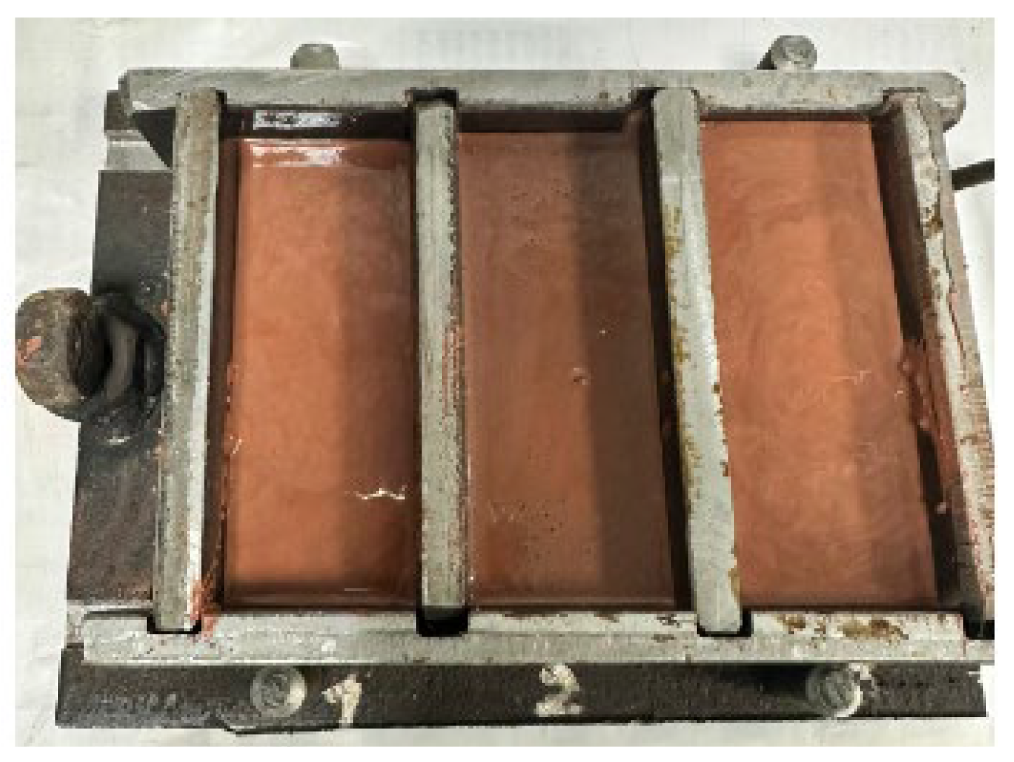
To obtain a certain shape of samples, three-channel molds made of St3ps steel were prepared. The size of one section (channel) is 40 × 40 × 100 mm. Molds measuring 100 × 100 × 10 mm were also prepared. Previously, the molds were cleaned of dirt, plaque, etc.
The molding mixture preparation process is shown in Figure 1 and Figure 2. The molds were used after sieving on sieves with chamotte fractions of 2.5; 1.0; 0.5; and 0.1 mm. So, 5 options of samples were prepared. Each version had 4 series: in the first series, a 1.0 mm chamotte fraction was used, in the second series a 2.5 mm chamotte fraction was used, in the third series a 0.5 mm chamotte fraction was used, and in the fourth series a 0.1 mm chamotte fraction was used.
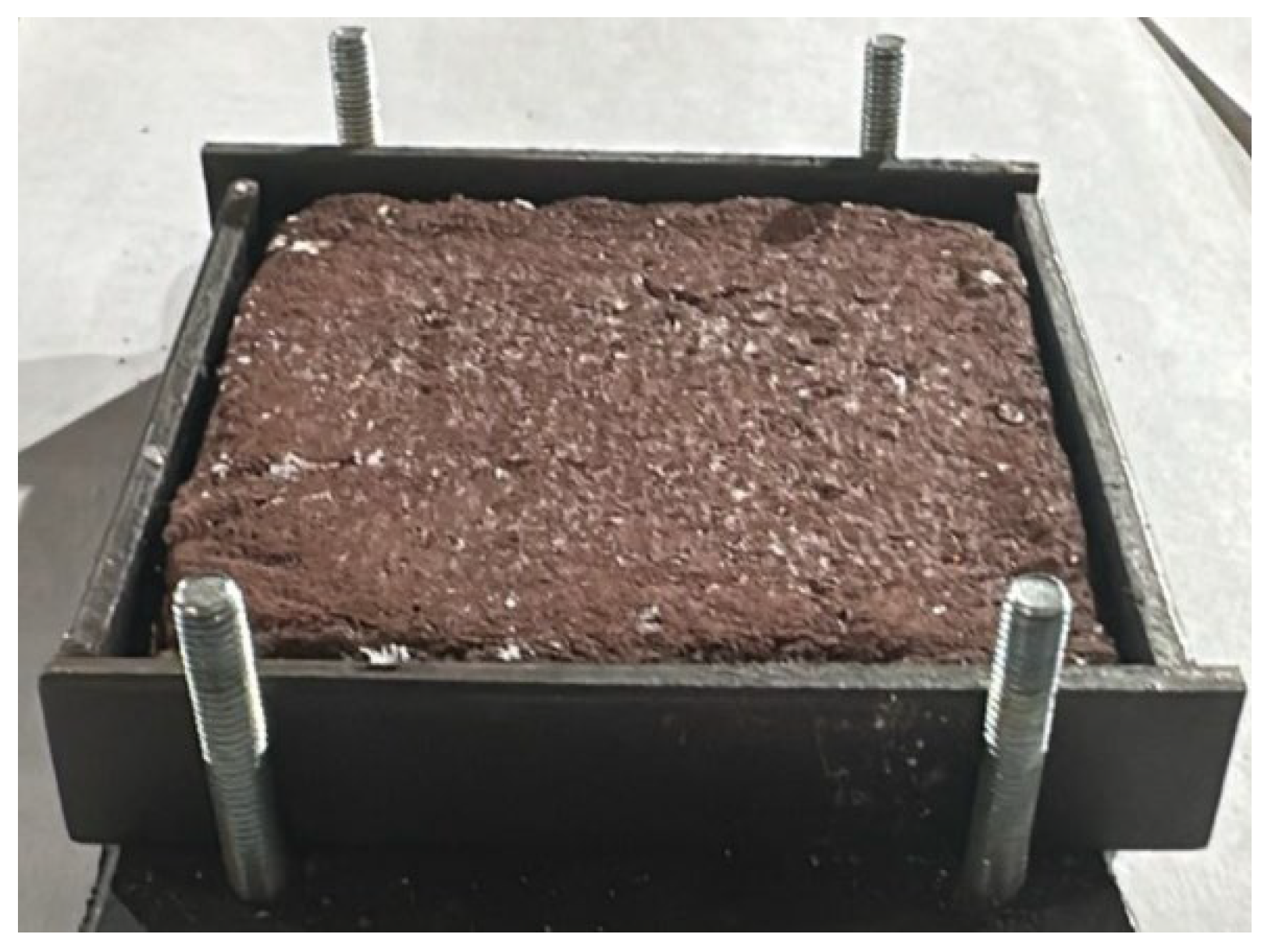
The dimensions of the obtained samples were 40 × 40 × 100 mm. To determine the thermal conductivity, samples of 100 × 100 × 10 mm were obtained (Figure 3).
The resulting moldable mixture was filled into molds, beaten, and placed in an electric CNOL furnace. Cooling of the mold was carried out together with the furnace to room temperature.

2.2. Material Characterization

(A) Determination of thermal conductivity GOST 12170-2021 [21]
The thermal conductivity was determined by the contact method of heat flow on the heat flux density and the temperature meter ITPMG4.03/X (I) “POTOK”, manufactured by SKB Stroypribor, Chelyabinsk, Russia, as well as by the stationary method on the device ITP MG-4 (SKB Stroypribor, Chelyabinsk, Russia).
The relationship between the heat flux density and thermal conductivity (Fourier law for a flat wall) was as follows:
q = λ·(ΔT/d) => λ = q·d/ΔT,
where q—heat flow density, W/m2;
  • λ—thermal conductivity of the material, W/(m·K);
  • d—sample thickness, m;
  • ΔT—temperature difference on both sides of the sample, K (°C).
(B) Determination of compressive strength (GOST 17177-94) [22]
The determination of the compressive strength was carried out on a laboratory test machine MI-40KU (Moscow, Russia). Prepared samples were installed between flat plates. The load was applied uniformly with increasing force until the sample was destroyed.
(C) Determination of open porosity GOST 2409-2014 [23]
The essence of the method was to measure the mass of water absorbed by a sample of dry material when completely immersed in water for a given time. A total of 500–700 mL of water was drawn into the container so that the samples were completely immersed in water.
Microstructure
The structure of the obtained samples was studied by the scanning electron microscope Carl Zeiss EVO-18, which was manufactured by Carl Zeiss Microscopy (Oberkochen, Germany) in order to explain and predict their properties and behavior during various physical and mechanical tests.

3. Results and Discussion

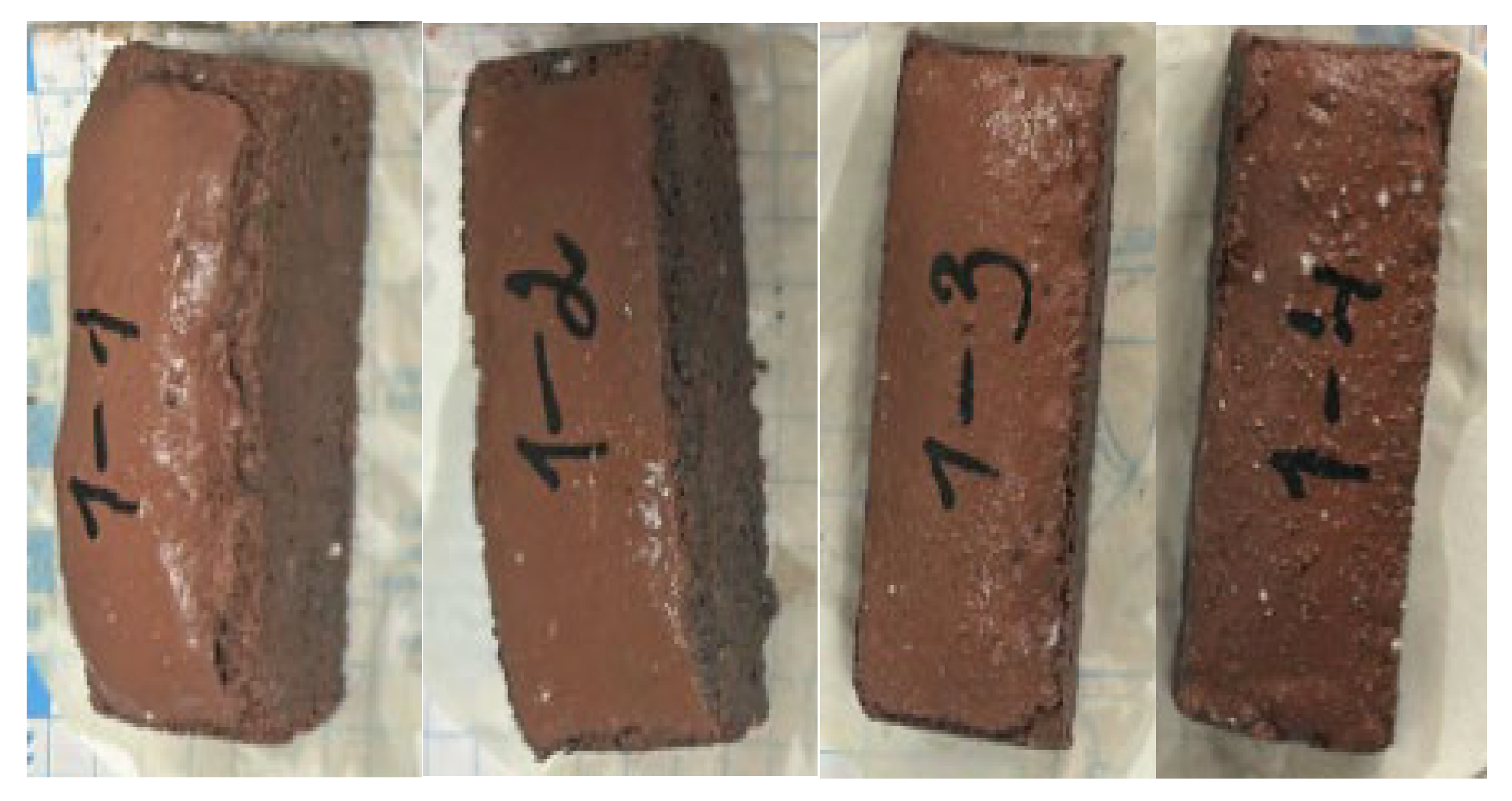
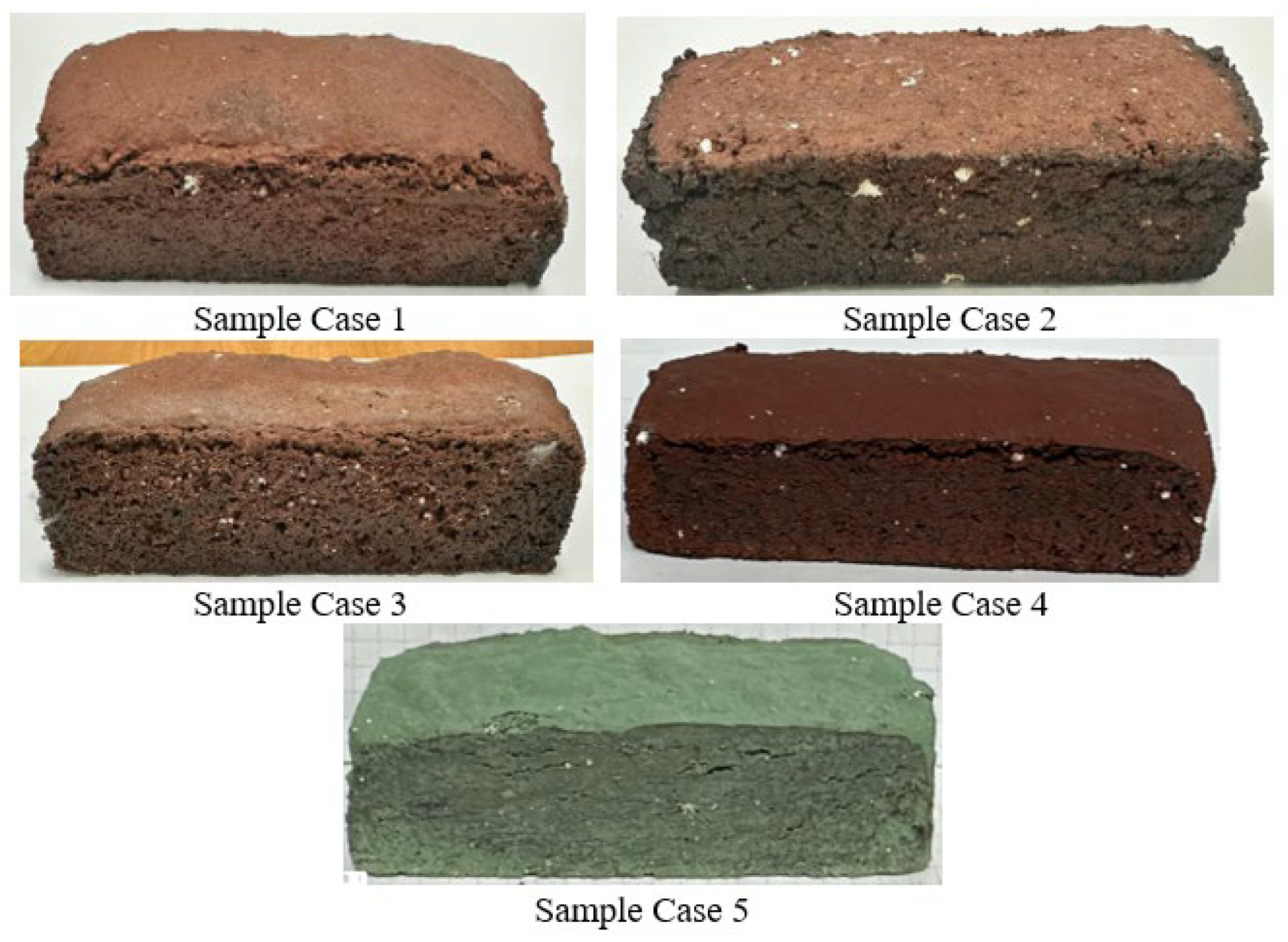
The obtained secondary refractory material has a rough surface, which was sufficiently strong; when tapping, it made a metallic sound.
A photo of the finished samples is shown in Figure 4.

3.1. Determination of Thermal Conductivity

The resulting heat-insulating material was tested to determine its physical and mechanical properties, namely thermal conductivity, porosity, and compressive strength.
The thermal conductivity results are presented in Table 2.
According to Table 2, the thermal conductivity value ranges from 0.167 to 0.388 W/(m·ºC), which corresponds to GOST 12170-2021, in which the thermal conductivity values are 0.03–15.0 W/m·K. The minimum value of thermal conductivity was in sample No. 2-4, and the maximum was in sample No. 3-3.

3.2. Determination of Compressive Strength

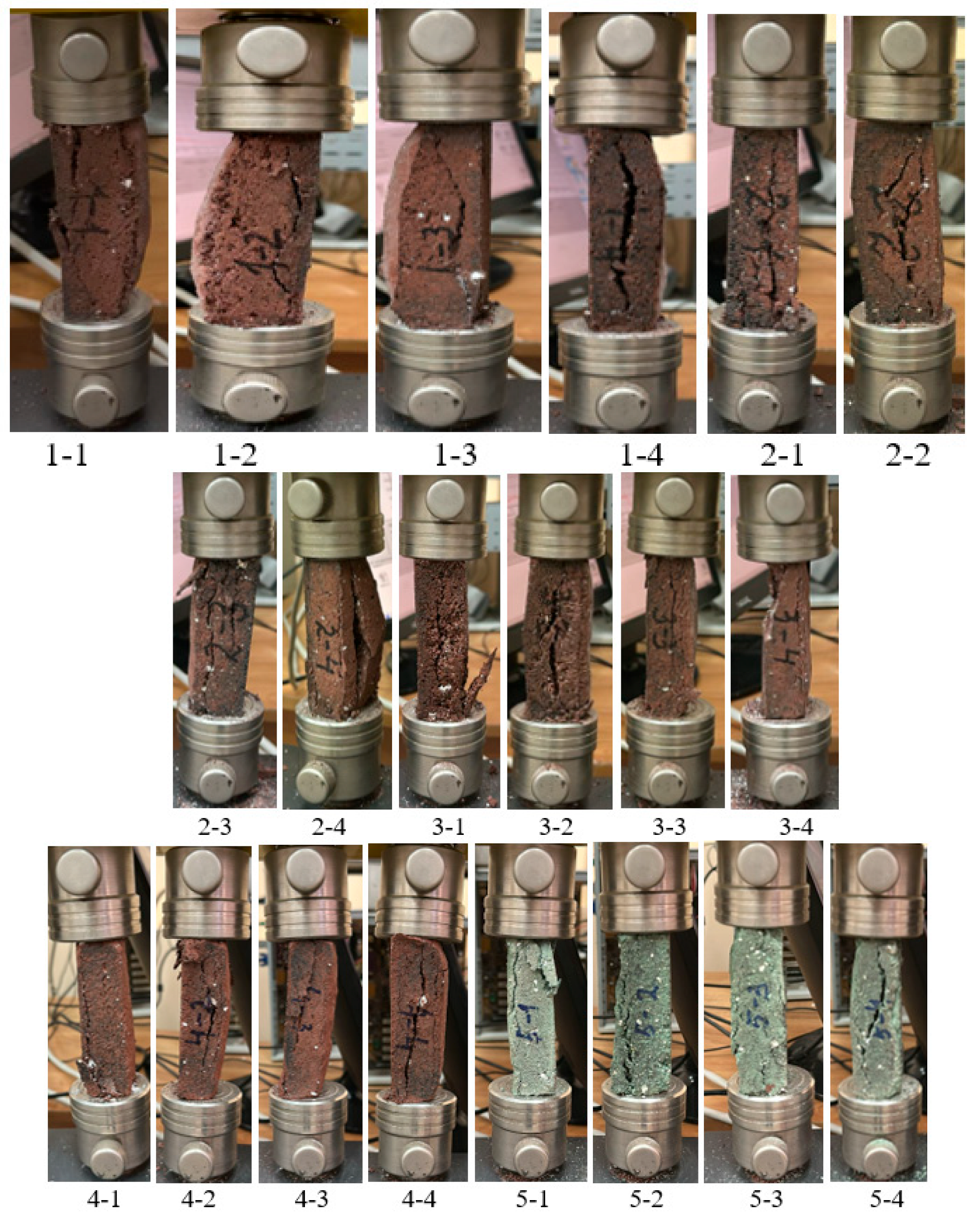
Figure 5 shows the behavior of the samples during the compression test.
The results were recorded in Table 3.
The maximum force value recorded at failure was automatically displayed on the machine’s digital indicator.
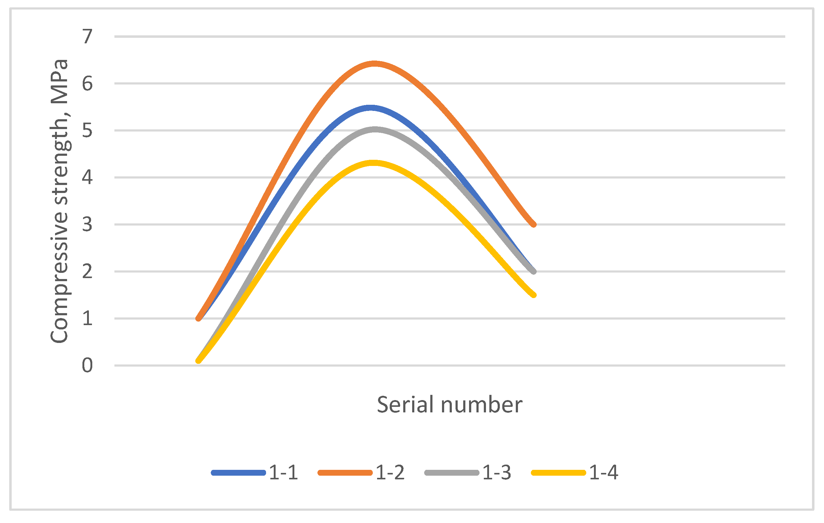
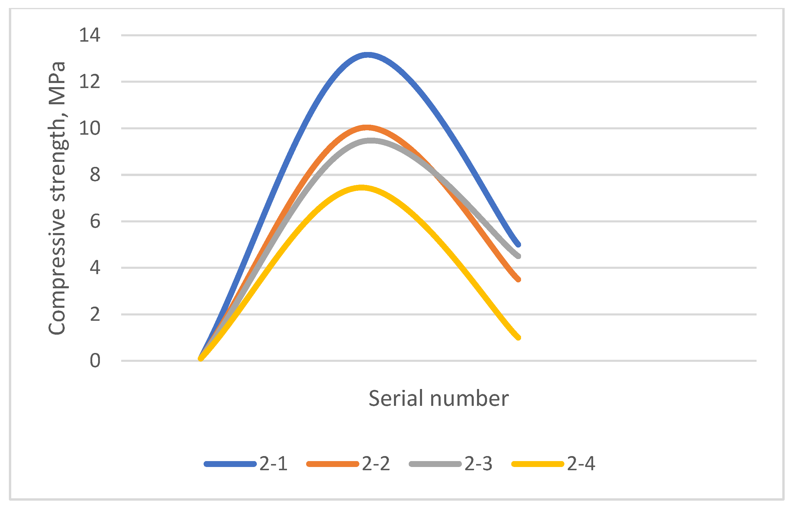
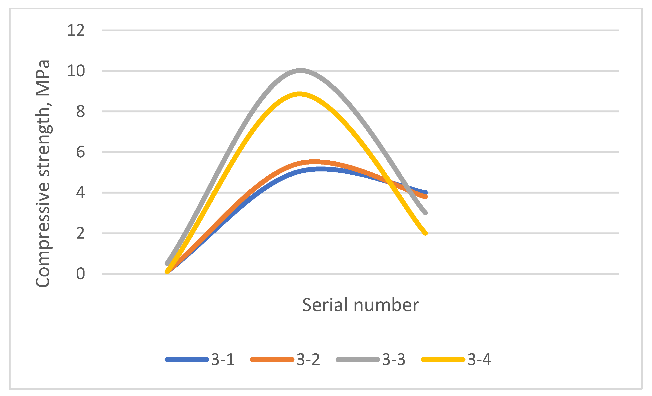
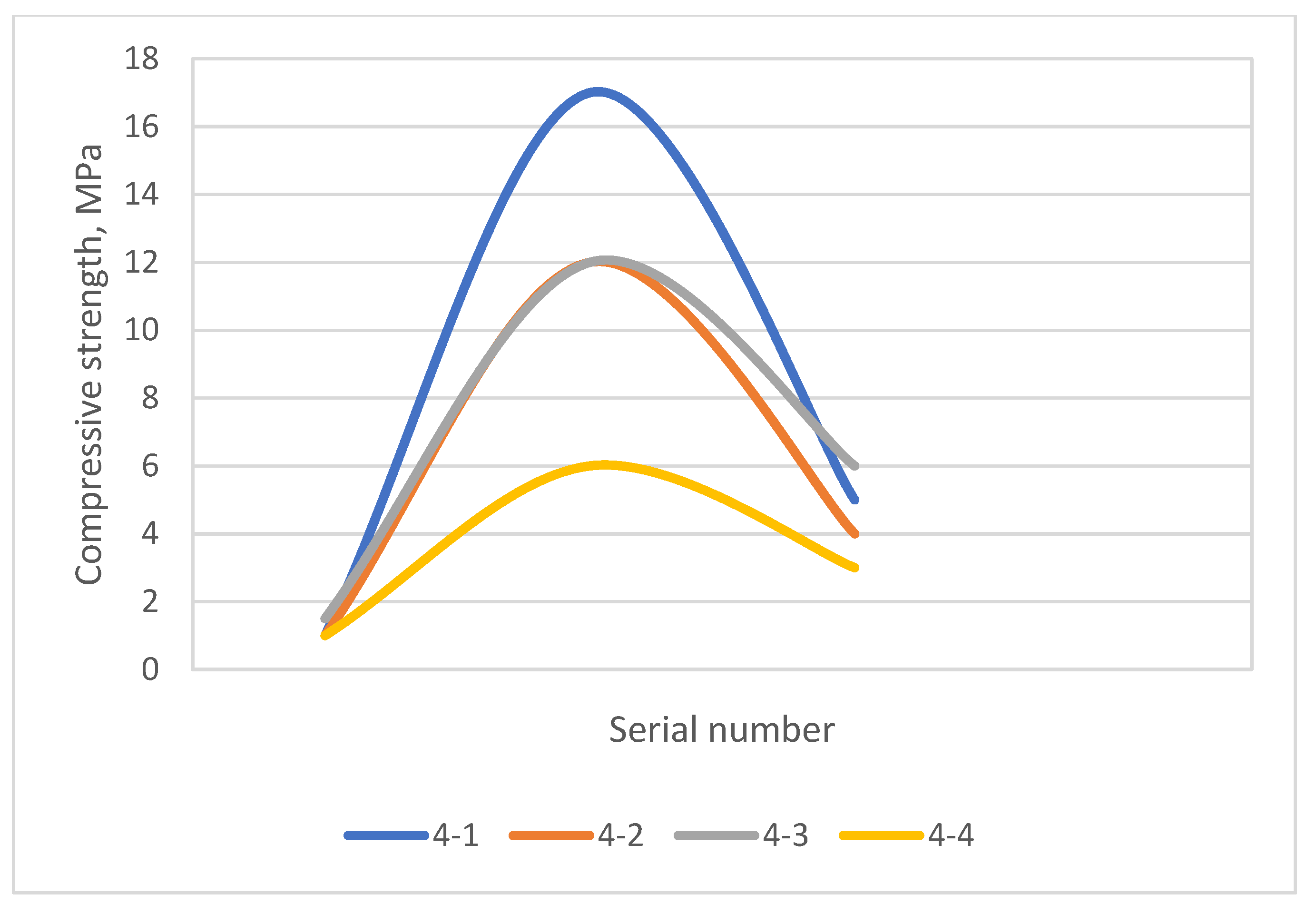
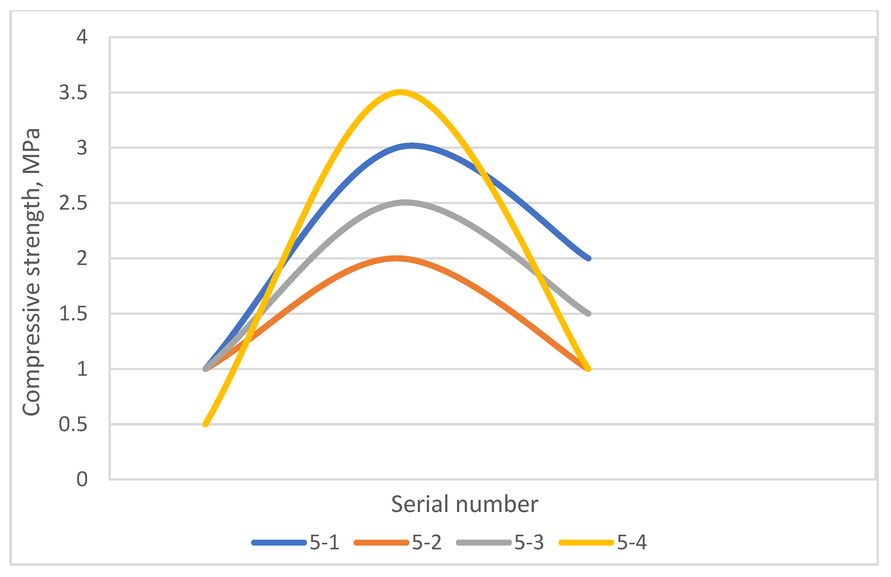
The compression diagram is shown in Figure 6, Figure 7, Figure 8, Figure 9 and Figure 10.
The results in Table 3 show that samples No. 2-1, 2-2, 2-3, 3-3, 4-1, 4-2, and 4-3 have the highest compressive strength. Sample 4-1 has the highest compressive strength (171.31 kgf/mm2). This is influenced by the presence of cement in the sample composition. Samples of series 5 have unsatisfactory compressive strength values (from 16.82 to 28.55 kgf/mm2).

3.3. Determination of Open Porosity

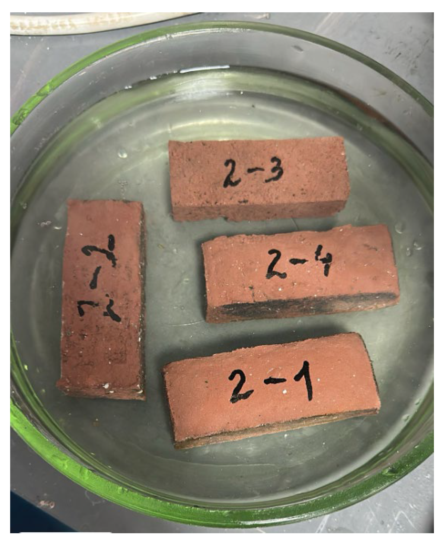
When immersing the samples, a slight gas emission was observed, which may indicate the presence of internal pores. All obtained samples after immersion in water did not separate and retained the appearance of Figure 11.
Figure 12 shows the samples on filter paper after removal from water.
The samples were dried until a constant weight was established, followed by weighing. The weights of the samples are in dry form, wet and dried, and the results from testing the samples are given in Table 4.
According to Table 4, the porosity values of the samples are 11.6–29.7%, which corresponds to the data of GOST 2409-2014 (no more than 30%), except for sample No. 1-1.

3.4. Microstructure

The material of the samples in series 1 has a fine and medium porous structure, with a significant number of open pores of various sizes. The pores are unevenly distributed, and both small uniform cells and large voids forming local decompressed zones are present. The structure is dense and granular (Figure 13).
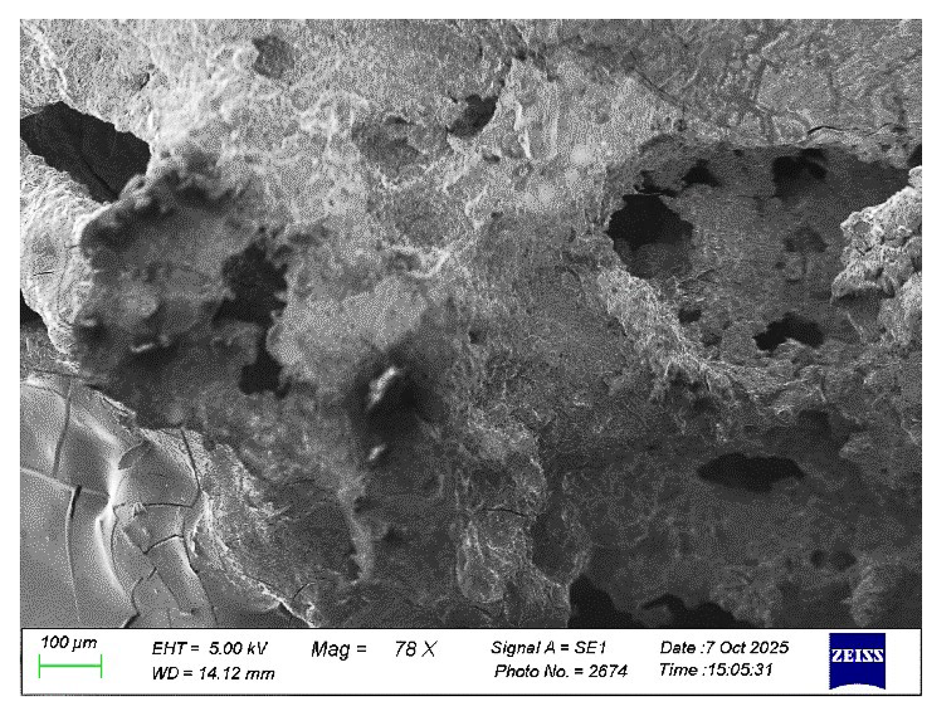
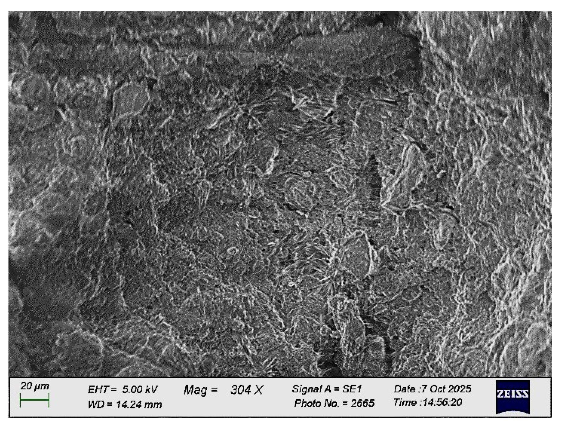
The porosity of the samples in series 2 is average, pores of round shape are observed that are irregularly located in the volume, and the structure is dense and fibrous, with a small number of microcracks. It crumbles less, as the edges of the fault are slightly denser (Figure 14).
The structure of the samples in series 3 is granular. The structure is dense, granular, and fibrous (Figure 15).
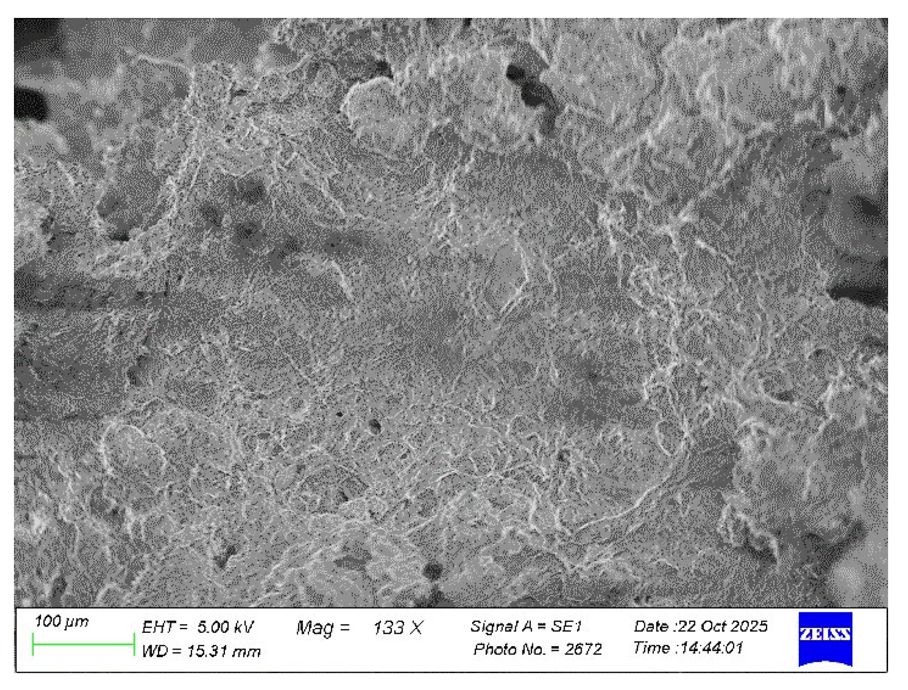
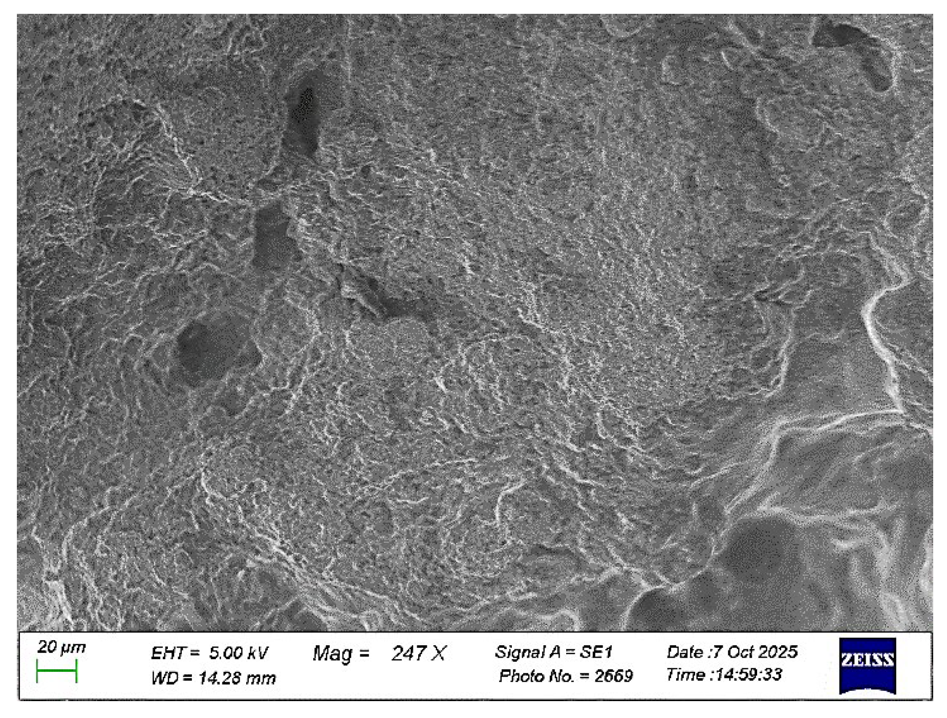
The structure of the samples in series 4 is dense and does not crumble. The body structure itself is dense and fibrous (Figure 16).
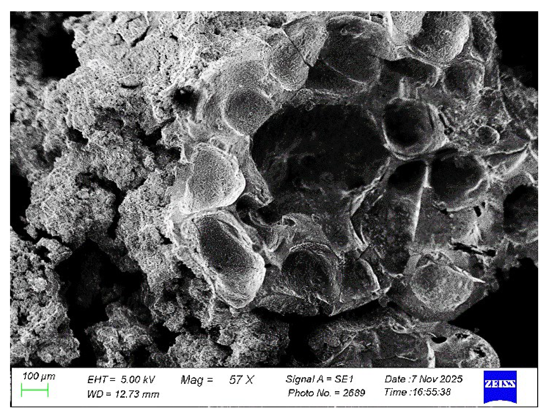
The structure of the samples in series 5 is porous and granular. The pores are rounded and unevenly distributed. The fracture is cup-loose. The body structure is loose (Figure 17).
When creating secondary samples, the material is dried at temperatures of 180–300 °C, followed by slow cooling in the furnace: that is, a non-fired technology was used. This mode eliminates the need for long-term isothermal exposure and additional power consumption at the cooling stage. Due to this, the total heat losses are reduced and the energy efficiency is increased compared to traditional firing modes. An assessment of the energy consumption and economic efficiency of the technology is given in Table 5.
The conducted energy consumption assessment showed that when heating the material to 300 °C, the specific energy consumption is approximately 0.25 kW h/kg, taking into account the efficiency of the equipment, which corresponds to ~0.013 USD/kg. In industrial conditions, with an increase in efficiency to 50–60%, this figure can be reduced to 0.15 kW h/kg (~0.009 USD/kg). For comparison, traditional refractory production technologies, including high-temperature firing (1000–1400 °C), require 1.5–2.5 kW h/kg, which corresponds to 0.085–0.13 USD/kg. Thus, the proposed technology provides a reduction in energy costs by 5–10 times. As production scales up, a further reduction in specific energy consumption is expected due to increased equipment efficiency, the use of production waste, and a reduction in heat loss. The energy consumption assessment is of a general nature and is based on the reference thermophysical data and typical efficiency values of heating equipment, since direct measurements of energy consumption were not carried out as part of the laboratory tests.
At the same time, the initial chamotte scrap has a number of specific properties due to its “thermal past,” since for a long time, the refractories withstood intense thermal loads during the operation of the thermal unit. As a result, modification changes in the crystal lattice parameters are completely completed in the refractory, and the structure of the material is compacted, which leads to an increase in strength properties.

4. Conclusions

The test results of the new secondary refractory material based on chamotte scrap showed good values of physical and mechanical properties: the secondary refractory material has properties close to GOST. The strength of the material is increased at a temperature of 180–300 °C, which eliminates the burning process and reduces energy and electrical costs.
This article shows the optimization of the formulation of secondary refractory materials based on chamotte scrap, which are planned to be used for the purpose of heat-protective materials in the lining of heat pipes of combined heat and power plants with a maximum operating temperature of 500 °C. The use of metallurgical waste to create refractory materials helps not only to reduce costs, but also to solve the problem of recycling industrial waste, which is important from an environmental point of view.
At the same time, there is no need for additional purchases of refractories abroad, thereby stabilizing the rhythm of production. The creation of new materials based on industrial waste leads to a decrease in the cost of production, an improvement in the environmental situation of the region by reducing the areas of dumps, saving natural resources, which contributes to the expansion of the country’s raw material base.
Research work in this area continues with the aim of determining the thermal stability of secondary materials, as well as determining the X-ray phase analysis.

Author Contributions

Conceptualization, V.M.; methodology O.M., V.M. and G.U., formal analysis, O.M. and Z.G.; investigation, O.M.; writing—original draft preparation, O.M., A.Y. and M.S.S.; writing—review and editing, G.U. and O.M., visualization, M.S.S. and A.Y.; supervision, O.M.; project administration, O.M.; funding acquisition, O.M. All authors participated in writing the paper. All authors have read and agreed to the published version of the manuscript.

Funding

This research received no external funding.

Institutional Review Board Statement

Not applicable.

Informed Consent Statement

Not applicable.

Data Availability Statement

The original contributions presented in this study are included in the article; further inquiries can be directed to the corresponding author.

Conflicts of Interest

Author Gulnara Ulyeva was employed by JSC Qarmet. The remaining authors declare that the research was conducted in the absence of any commercial or financial relationships that could be construed as a potential conflict of interest.

References

  1. Horckmans, L.; Nielsen, P.; Dierckx, P.; Ducastel, A. Recycling of refractory bricks used in basic steelmaking: A review. Resour. Conserv. Recycl. 2019, 140, 297–304. [Google Scholar] [CrossRef]
  2. Red, B.L. Method of Manufacturing Chromium Oxide Refractory Articles. Patent RU 2348593 C2, 3 October 2009. [Google Scholar]
  3. Vladimirov, V.S.; Moisis, S.E.; Karpukhin, I.A.; Korsun, S.D.; Dolgov, V.I. Method for Producing Porous Refractory Material. Patent RU 2197450 S1, 27 January 2003. [Google Scholar]
  4. Vakalova, T.V.; Pogrebenkov, V.M.; Chernousova, O.A. Charge for the Manufacture of Chamotte Refractories. Patent RU 2213713C2, 10 October 2003. [Google Scholar]
  5. Peretokina, A.; Peretokina, N.A.; Doroganov, V.A.; Grudina, V.A.; Pogikyan, A.N. Thermal insulation properties of refractory materials on artificial ceramic bundles. Refract. Tech. Ceram. 2016, 57, 189–191. [Google Scholar] [CrossRef]
  6. Evtushenko, E.I.; Peretokina, N.A.; Doroganov, V.A. Heat insulation materials based on artificial ceramic binders of different composition. Vestn. V. G. Shukov BGTU 2013, 149–151. [Google Scholar]
  7. Peretokina, N.A.; Doroganov, V.A. Development and study of the compositions of unshaped fireclay-based heat-insulating refractories and a technology for making them. Refr. Indust. Ceram. 2011, 52, 52–54. [Google Scholar] [CrossRef]
  8. Krutikhin, A.L.; Sobyanin, M.I.; Chuprakov, A.V.; Sinitsyn, A.P. Refractory Concrete Mixture. Patent RU 2232734 S2, 20 July 2004. [Google Scholar]
  9. Chaplygin, B.A.; Lonzinger, T.M.; Afanasyev, A.A.; Netsvetaeva, N.P.; Skotnikov, V.A.; Dyatlov, V.V. Refractory Mass and Method of Obtaining Refractory Mass. Patent RU2365562C2, 27 August 2009. [Google Scholar]
  10. Sembiring, S.; Simanjuntak, W.; Situmeang, R.; Riyanto, A.; Junaidi, J. Structural and Physical Properties of Refractory Cordierite Precursors Prepared from Rice Husk Silica with different MgO Addition. Ceram.-Silik. 2018, 62, 163–172. [Google Scholar] [CrossRef]
  11. Asainova, D.A.; Merkulov, V.V.; Akhmetova, G.E.; Ulyeva, G.A.; Khlebnikov, S.I.; Pak, V.P. Refractory Lining Material from Metallurgical Waste. No. 6439, 24 September 2020. [Google Scholar]
  12. Ulyeva, G.A.; Akhmetova, G.E.; Tuyskhan, K.; Volokitina, I.E. Application of spark plasma sintering as a method for producing new ceramic materials from silicon production waste. Chem. Technol. Metall. 2024, 59, 605–611. [Google Scholar]
  13. Ulyeva, G.A.; Merkulov, V.V.; Yakovleva, D.A.; Volokitina, I.E. Choice rationale of materials for road marking in order to develop its production technology. Eurasian Phys. Tech. J. 2025, 22, 83–92. [Google Scholar] [CrossRef]
  14. Ulyeva, G.A.; Tuyskhan, K.; Matsugina, E.M.; Volokitina, I.E.; Akhmetova, G.E. Actual progress of production waste disposal problems. Izv. Ferr. Metall. 2025, 68, 131–138. [Google Scholar]
  15. Pivinskii, Y.E.; Rozhkov, E.V. Ceramic castables-final stage in the evolution of low-cement refractory castables. Part 3. Refract. Ind. Ceram. 2003, 44, 134–140. [Google Scholar] [CrossRef]
  16. Pivinskii, Y.E. HCBS ceramic concretes in the XXI century-problems and prospects for applying technology in the field of silicate materials science. Part 1. Refract. Ind. Ceram. 2011, 52, 107–115. [Google Scholar] [CrossRef]
  17. Podbolotov, K.B.; Volochko, A.T.; Khort, N.A.; Gusarov, S.V. Refractory Materials Based on Secondary Resources and Phosphate Compounds. Refract. Ind. Ceram. 2019, 59, 579–582. [Google Scholar] [CrossRef]
  18. Arinova, S.K.; Kvon, S.S.; Kulikov, V.Y.; Issagulov, A.Z.; Altynova, A.E. Utilization of Coal Ash for Production of Refractory Bricks. J. Compos. Sci. 2025, 9, 275. [Google Scholar] [CrossRef]
  19. Doroganov, V.A.; Pivinskii, Y.E.; Evtushenko, E.I. Plastic molding refractory mixes based highly-concentrated ceramic binder suspensions of high-alumina fireclay. Refract. Ind. Ceram. 2007, 48, 63–68. [Google Scholar] [CrossRef]
  20. GOST 390-96; Refractory Materials. General Technical Conditions. Russian Institute of Standardization: Moscow, Russia, 1996.
  21. GOST 12170-2021; Refractories. Stationary Method for Determining the Thermal Conductivity Coefficient. Russian Institute of Standardization: Moscow, Russia, 2021; p. 22.
  22. GOST 17177-94; Thermal Insulation Test Materials and Products. Interstate Scientific and Technical Commission for Standardization and Technical Standardization in Construction (MNTKS): Moscow, Russia, 2001; p. 40.
  23. GOST 2409-2014; Refractories. Method of Determination of Apparent Density, Open and Total Porosity, Water Absorption. Standartinform: Moscow, Russia, 2014; p. 10.
Figure 1. Sample preparation process.
Eng 07 00249 g001
Figure 2. Three-channel press molds with source materials.
Eng 07 00249 g002
Figure 3. Samples intended for determining thermal conductivity.
Eng 07 00249 g003
Figure 4. Photograph of the samples.
Eng 07 00249 g004
Figure 5. Behavior of specimens during compression testing.
Eng 07 00249 g005
Figure 6. Compression diagram of samples of series 1.
Eng 07 00249 g006
Figure 7. Compression diagram of samples of series 2.
Eng 07 00249 g007
Figure 8. Compression diagram of samples of series 3.
Eng 07 00249 g008
Figure 9. Compression diagram of samples of series 4.
Eng 07 00249 g009
Figure 10. Compression diagram of samples of series 5.
Eng 07 00249 g010
Figure 11. Samples immersed in water.
Eng 07 00249 g011
Figure 12. Samples were weighed before and after exposure to water.
Eng 07 00249 g012
Figure 13. Sample series 1-4.
Eng 07 00249 g013
Figure 14. Sample series 2-2.
Eng 07 00249 g014
Figure 15. Sample series 3-1.
Eng 07 00249 g015
Figure 16. Sample series 4-2.
Eng 07 00249 g016
Figure 17. Sample series 5-2.
Eng 07 00249 g017
Table 1. Composition of the initial components.
Source MaterialsVariant, g
12345
1Baking soda-5.05.05.05.0
2Aluminum oxide (Al2O3)10.010.010.010.010.0
3Titanium dioxide (TiO2)10.010.010.010.010.0
4Zinc oxide (ZnO)10.010.05.010.010.0
5Zirconium oxide (ZrO2)5.05.05.05.05.0
6Chromium oxide (Cr2O3)5.05.05.05.05.0
7Iron oxide (Fe2O3)5.05.05.05.0-
8Cement (M400)-5.05.05.05.0
9Lime (CaO)5.05.05.05.05.0
10Microsilica5.05.05.05.05.0
11Chamotte30.030.030.030.035.0
12Liquid glass, mL100-10010050
 Drying temperature, °C300250200180250
Table 2. Results of thermal conductivity determination.
Sample NumberThe Value of Thermal Conductivity
Contact Method, λ, W/(m·K)Stationary Method, λ, W/(m·ºC)
1-10.0710.299
1-20.0680.254
1-30.0560.168
1-40.0380.223
2-10.0760.190
2-20.0740.225
2-30.0700.198
2-40.0710.167
3-10.0510.385
3-20.0830.324
3-30.0440.388
3-40.0670.241
4-10.0850.211
4-20.0860.302
4-30.0850.186
4-40.0850.218
5-10.0730.157
5-20.0780.175
5-30.0750.192
5-40.0820.217
Table 3. Results obtained.
SampleP,кHS, mm2σ, kgf/mm2Behavior
1-15.4810.055.88There was a crack from the edge, the sample collapsed
1-26.410.065.26A crack also appeared, but the sample was not destroyed from the edge
1-3510.051.0A crack appeared in the center, but the sample was not destroyed
1-44.310.043.84The destruction of the sample occurred immediately after the crack appeared
2-113.110.0133.58Destruction of the sample occurred in the center due to the formation of a crack
2-210.010.0102.0The destruction of the sample occurred immediately after the crack appeared
2-39.410.095.85Destruction of the sample occurred in the center due to the formation of a crack
2-47.4510.076.0The development of the crack began immediately along the hump of the sample
3-15.010.051.0A crack was formed in the center, the sample was destroyed
3-25.410.055.1A crack was formed in the center, the sample was destroyed
3-31010.0102.0A crack was formed in the center, the sample was destroyed
3-48.8510.090.24The sample was destroyed at the end
4-116.810.0171.31A crack formed in the center, the sample did not collapse, strong
4-211.310.0115.22A crack appeared in the center, the sample was destroyed
4-311.210.0114.0A small crack appeared from one corner, the sample was strong, not destroyed
4-46.510.066.28Crack appeared, sample destroyed
5-12.710.027.53A crack appeared from one corner, the sample was strong, not destroyed
5-21.810.018.35A crack appeared along the edge, the sample was destroyed, also along the edge, the body of the sample itself was strong
5-31.6510.016.82A crack formed, the sample collapsed, but the sample body was strong
5-42.810.028.55A crack formed in the center, the sample did not collapse, fragile
Table 4. Porosity test results.
SeriesInitial Mass, gMass After Exposure to Water, gOpen Porosity, %
1-1132.55175.9032.7
1-2127.70165.6029.7
1-3118.80152.6228.5
1-4121.15150.8024.5
2-1140.65176.4025.3
2-2122.47142.2016.1
2-3135.69166.2022.5
2-4140.33166.8018.9
3-1139.42165.6518.8
3-2135.45163.5320.7
3-3138.70179.3029.3
3-4140.0184.1031.5
4-1169.48195.2215.2
4-2165.40192.6516.5
4-3167.15189.1413.2
4-4157.67175.9111.6
5-1135.36166.6523.0
5-2139.23167.7020.4
5-3153.82186.1521.0
5-4144.58180.3224.7
Table 5. Comparative assessment of energy consumption and economic efficiency of the developed technology and traditional firing of refractories.
IndicatorProposed Technology
(up to 300 °C)
Traditional Technology
(1000–1400 °C)
Processing temperature, °C180–3001000–1400
Specific energy consumption, kW h/kg0.15–0.251.5–2.5
Energy cost, USD/kg0.009–0.0130.085–0.13
Share of energy in cost price, %1–28–15
The need for firingis absentit is required
Heat loss levellowhigh
Technological complexitylowhigh
Energy savings~5–10-
Disclaimer/Publisher’s Note: The statements, opinions and data contained in all publications are solely those of the individual author(s) and contributor(s) and not of MDPI and/or the editor(s). MDPI and/or the editor(s) disclaim responsibility for any injury to people or property resulting from any ideas, methods, instructions or products referred to in the content.