Article

Modification of the Tribomechanical Cutting Regime in Longitudinal-Torsional Ultrasonic Milling: From Adhesion to Controlled Fragmentation


by
Oussama Beldi
1,2,
Tarik Zarrouk
1,2,*,
Ahmed Abbadi
2,
Mohammed Nouari
3,
Wenfeng Ding
4,*,
Mohammed Abbadi
2,
Jamal-Eddine Salhi
5,6 and
Mohammed Barboucha
1
1
Centre de Recherche (CREHEIO) de L’Ecole des Hautes Etudes d’Ingénierie, Equipe de Production Intégrée, Oujda 60000, Morocco
2
Lean Manufacturing et Modélisation Mécanique, Ecole Nationale des Sciences Appliquées, Oujda 60000, Morocco
3
Laboratoire d’Energétique et de Mécanique Théorique et Appliquée, Ecole des Mines de Nancy, Université de Lorraine, F-88100 Saint Dié des Vosges, France
4
College of Mechanical and Electrical Engineering, Nanjing University of Aeronautics and Astronautics, Nanjing 210016, China
5
Department of Pure and Applied Mathematics, Saveetha School of Engineering, Saveetha Institute of Medical and Technical Sciences (SIMATS), Thandalam, Chennai 602105, Tamil Nadu, India
6
Laboratory of Energetics (LE), Faculty of Sciences, Abdelmalek Essaadi University, Tetouan 93000, Morocco
*
Authors to whom correspondence should be addressed.
Eng 2026, 7(4), 177; https://doi.org/10.3390/eng7040177
Submission received: 26 February 2026 / Revised: 22 March 2026 / Accepted: 26 March 2026 / Published: 13 April 2026
(This article belongs to the Special Issue Emerging Trends and Technologies in Manufacturing Engineering)

Abstract

Machining Nomex honeycomb structures presents a major challenge due to their thin-walled architecture, orthotropic behavior, and sensitivity to adhesion and delamination. This study develops a three-dimensional numerical model using Abaqus/Explicit to analyze ultrasonic vibration-assisted milling in longitudinal and longitudinal-torsional modes. The model incorporates orthotropic behavior with progressive damage based on Tsai-Wu and experimental friction calibration to accurately reproduce tribological conditions. A parametric analysis examines the effect of vibration mode, amplitude (5–25 µm), frequency (21–22.5 kHz), cutting width, and tool geometry on stresses, bond wear, and material buildup. An optimal coefficient of friction ensures excellent simulation–experiment agreement. Compared to conventional milling, the longitudinal-torsional configuration reduces cutting forces by up to 50%, while frequency optimization allows for gains of 40 to 60%. Hybrid vibration coupling establishes intermittent contact and oscillatory micro-shearing, limiting adhesion and build-up. Thus, longitudinal-torsional assistance improves tribological stability, tool life and wall integrity, offering a validated digital strategy to optimize ultrasonic milling of composite honeycomb structures.

1. Introduction

The core of Nomex honeycomb structures (NHC) is formed of aramid fibers impregnated with a phenolic resin. This combination of materials gives these honeycomb composites remarkable properties, including high mechanical strength, high toughness and excellent stability against chemical agents [1,2,3]. Due to their exceptional mechanical performance, NHC cores are widely used in the aerospace and aeronautical fields, particularly for the design of aircraft wings and tail assemblies [4,5,6,7]. Nevertheless, machining NHC structures remains particularly complex for researchers and engineers due to the thinness of their walls, their honeycomb geometry, and the heterogeneous nature of Nomex paper. Given these constraints, in-depth experimental investigations are essential to better understand and characterize their behavior during machining operations. These topics allow for a detailed examination of the cutting mechanism and provide the precise data necessary for developing advanced numerical models to predict machining behavior and improve operating parameters [8,9]. Machining NHC cores using conventional methods with cutting tools such as milling cutters or lathes presents limitations in terms of precision and surface quality, including burr formation, cell deformation, and aramid fiber tear-off, even with optimized tools [10]. Due to the inadequacies of conventional machining methods in controlling the particularities of NHC and avoiding an unsatisfactory surface condition, it is essential to develop more efficient machining processes, adapted to its architecture, and to adjust the cutting conditions to limit cellular deformations and fiber tearing. To address these constraints, ultrasonic-assisted rotary machining (UAM) technology has been proposed as an alternative to conventional processes for manufacturing NHCs. It relies on the application of ultrasonic vibrations along the tool axis, which allows for better control of cell deformation and improved cutting of aramid fibers [11,12,13,14]. RUM technology is attracting increasing interest for machining a wide range of conductive and dielectric materials, including titanium [15,16], aluminum [17,18,19,20] and nickel [20,21,22] alloys, as well as glass [23,24], ceramics [25,26] and composite materials [27,28,29,30]. The study by Xia et al. [31] aimed to optimize the structural design of a circular disc ultrasonic tool and to examine the impact of its geometric parameters on the energy density and stiffness of the tool, revealing that the machining efficiency of the NHC core is strongly influenced by the cutting angle, the tool radius and the amplitude of the vibrations. Ahmed et al. [32] compared the efficiency of three methods of machining NHC cores: traditional machining, ultrasonic rotary machining (RUM) and laser machining, highlighting that numerical modelling is a relevant and reliable tool to complement experimental investigations, due to the high costs associated with the implementation of an experimental device. The choice of constitutive law is crucial, as the simulation of the NHC walls relies primarily on elastoplastic, isotropic, or orthotropic models. The isotropic elastoplastic approach, while simpler to apply, does not fully account for the composite nature of the material, whereas the more accurate orthotropic approach incorporates mechanical properties dependent on fiber orientation. The coefficient of friction is a crucial parameter in modeling and governing the interactions between the tool and the material. Its proper management is essential to guarantee the accuracy of simulations and conduct a thorough process analysis. Numerical simulation of honeycomb structure machining assisted by RUM (rotary machining by ultrasonic vibrations) technology is a rapidly growing research area, still marked by a limited number of in-depth studies. Existing work has mostly focused on the application of longitudinal ultrasonic vibrations to improve the machining performance of alveolar structures [33,34]. Ultrasonic vibration-assisted milling offers significant advantages, including a reduction in cutting forces. Although the physical mechanism of intermittent contact between the tool and the workpiece remains poorly understood, recent work has developed an analytical model combining kinematic analysis and machining mechanics. Recently, an analytical model was proposed to predict these forces by combining the kinematic analysis of the tool–workpiece contact with the mechanics of machining, experimentally validated on an aluminum alloy, opening the way to a better understanding and prediction of cutting phenomena in ultrasonic milling. The obtained results on an aluminum alloy 2A12 show that the predicted forces differ on average by only 13.6% in the feed direction and 13.8% in the cutting direction compared to experimental measurements, demonstrating the effectiveness and reliability of the model for predicting cutting forces in ultrasonic milling [35]. Modeling studies have been conducted in the literature concerning the milling of Nomex honeycomb structures (NHC). In this study, an approach combining experimental tests and 3D numerical simulation using Abaqus Explicit was developed to analyze cutting forces, surface quality, and chip accumulation, highlighting the effectiveness of RUM technology and ultrasonic vibrations in improving the machinability of this complex structure [36]. However, numerical and experimental studies have revealed certain inherent limitations of this vibration mode. Therefore, coupling longitudinal and torsional vibrations appears to be a promising approach for further improving the machining process. However, studies that have attempted to model this technique remain partial, particularly due to insufficient consideration of contact conditions, the coefficient of friction and more realistic material behavior laws. This study proposes a 3D numerical model incorporating experimental calibration of the friction coefficient, ensuring a faithful simulation of real tribological conditions. It demonstrates that the longitudinal-torsional mode reduces cutting forces while limiting adhesion and material buildup on the cutting tool. Identifying optimal vibration parameters allows for the establishment of a stable intermittent contact regime, improving tool durability and cut quality. This constitutes an integrated approach combining advanced modeling, experimental validation, and RUM process optimization for NHC structures.

2. Materials and Methods

2.1. Experimental Setup

RUM-assisted milling tests of NHC structures were performed on the THU Ultrasonic 850 ultrasonic machine developed by Tsinghua University in Beijing, China (Figure 1) [32]. The setup included a BT-40 tool holder, an ultrasonic system, a generator, a Kistler dynamometer, and the machine spindle, allowing the required experimental data to be collected during machining. The horn shown in Figure 1 is integrated into the tool system to provide audible feedback upon activation or under certain operating conditions. It is electrically connected to the tool via an internal circuit linking its contacts to the BT-40 handle, which transmits the operator’s command to the tool and simultaneously triggers the horn’s audible signal. Thus, when a predefined condition is met or the operator activates the handle, the horn provides immediate audible feedback. The performance of the THU Ultrasonic 850 machine is based on fundamental parameters, including an ultrasonic frequency of 23 kHz, a maximum power of 2 kW, a spindle speed of up to 10,000 rpm, and a maximum vibration amplitude of 27 μm. These characteristics determine the machine’s ability to perform precise and efficient machining operations.

2.2. Physical and Mechanical Parameters of the Structure and the Cutting Tool

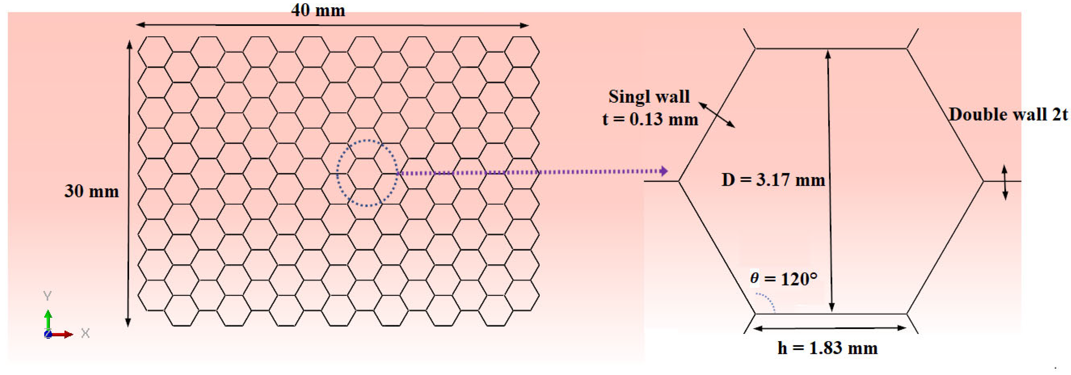
A detailed description of the mechanical properties and geometric characteristics of the structure to be machined and of the cutting tool is essential to establish a reliable and representative finite element machining model. The quality of the numerical results depends largely on the precision with which these parameters are defined, as they directly influence the simulated mechanical response and the accuracy of the predictions obtained. With this in mind, the NHC structure considered in this study was developed in accordance with the experimental protocol carried out [32]. The overall dimensions of the structure as well as the geometric characteristics of the alveolar cells have been integrated into the numerical model and are detailed in Figure 2, thus ensuring rigorous consistency between the experimental approach and the simulation.
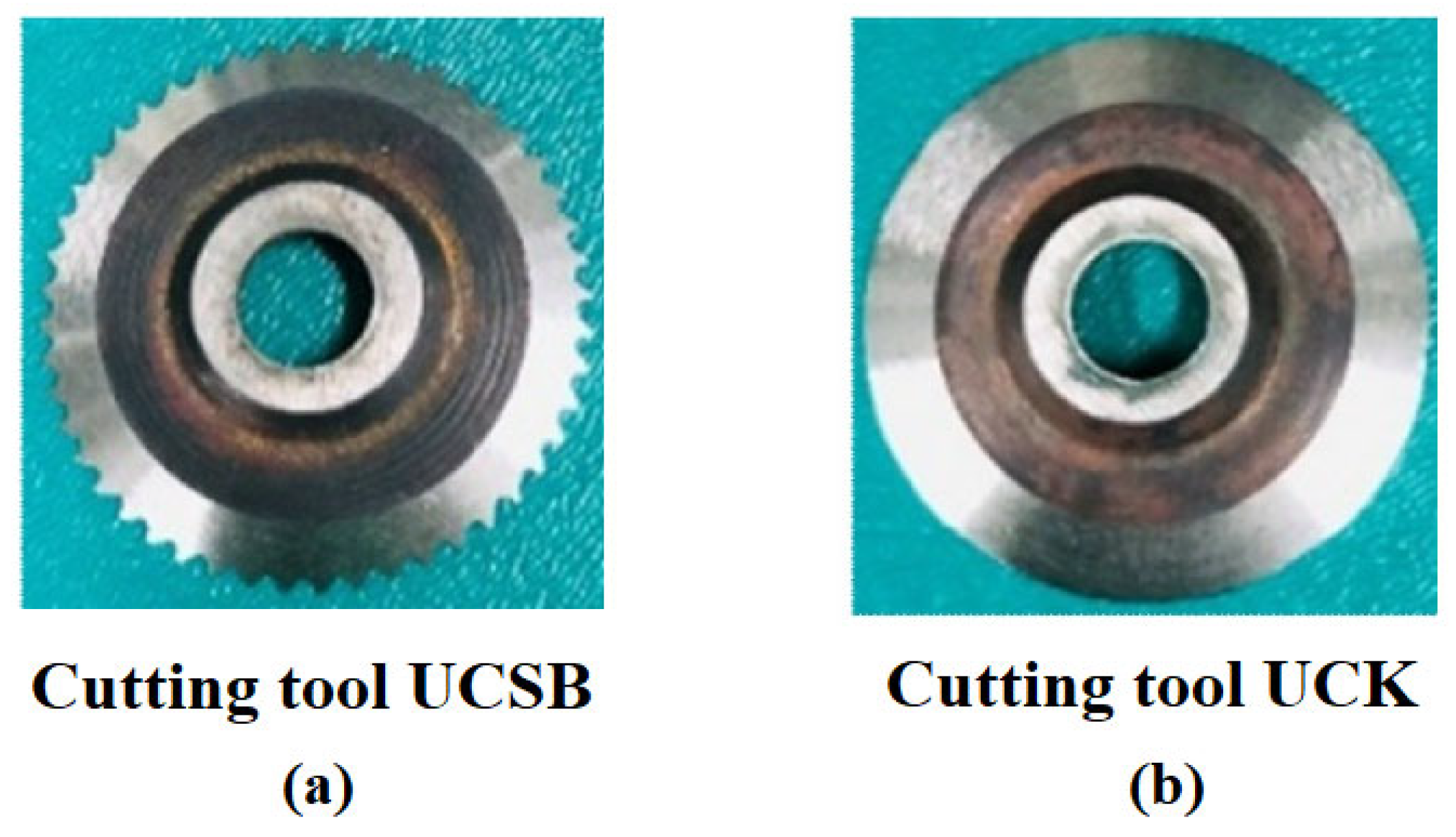
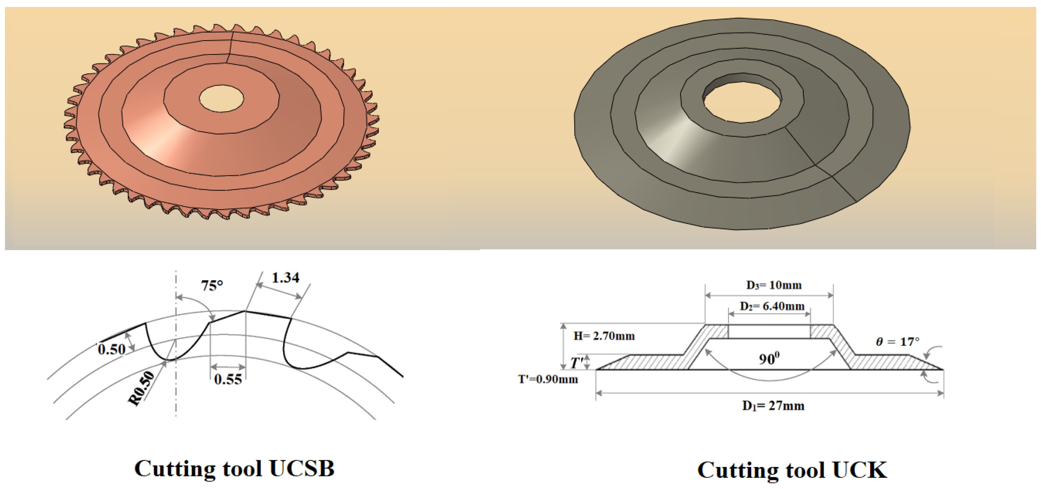
In accordance with the experimental protocol, the machining of the NHC core was carried out using two ultrasonic circular milling cutters with distinct geometries, designated UCSB and UCK, made of HSS-W18Cr4V high-speed steel (Figure 3) [32]. These cutters were designed according to the geometric parameters defined during the experimental tests (Figure 4).

3. Formulation of the Numerical Model

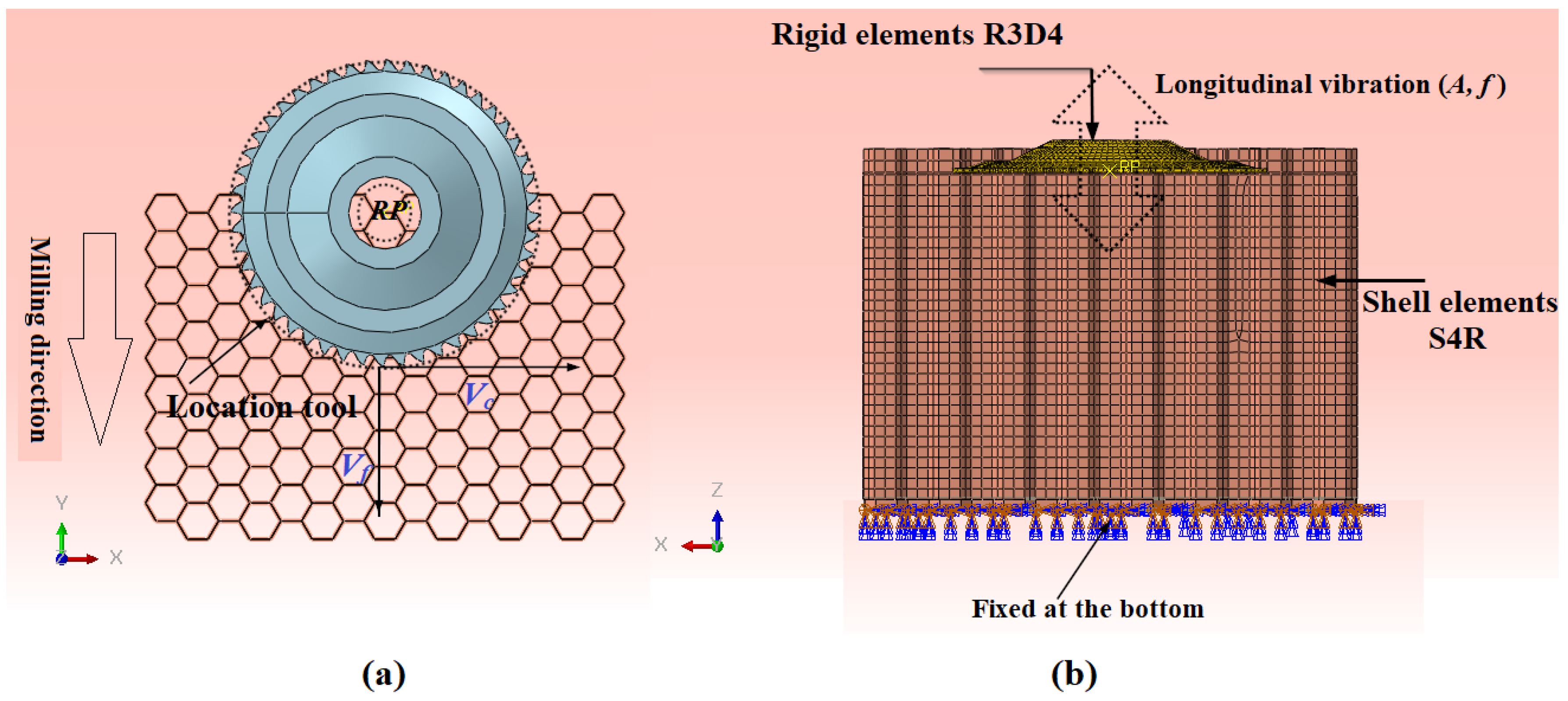
This contribution focuses on the simulation of the cutting process of a Nomex honeycomb structure assisted by ultrasonic vibrations, using a 3D numerical model developed with Abaqus/Explicit software (version 6.17). The design of the Nomex honeycomb structure (NHC) was carried out according to experimental characteristics. This structure consists of a periodic network of hexagonal cells formed by thin walls of Nomex paper impregnated with phenolic resin. The core architecture features two types of walls: single-cell walls, representing approximately two-thirds of the structure, and double-cell walls, constituting the remaining third. In the numerical model, the thicknesses of the single and double walls were set at 0.13 mm and 0.26 mm respectively to accurately reproduce the actual configuration of the material. For the numerical discretization, the walls of the honeycomb structure were meshed using four-node S4R shell elements with reduced integration, while the cutting tools, considered rigid during milling, were represented by four-node rigid quadrilateral elements of type R3D4 (Figure 5b). A mesh size of 0.35 mm was chosen to ensure an optimal balance between numerical accuracy and computational cost, leading to an overall model composed of 24,965 elements and allowing a detailed representation of the critical interaction zones between the tool and the structure. The interaction between the cutting tool and the Nomex honeycomb structure was described using a penalty contact formulation, allowing for realistic reproduction of contact conditions and friction mechanisms while ensuring the numerical stability of the simulations. In order to take into account the effect of ultrasonic vibrations on the tribological behavior of the tool, the coefficient of friction was calibrated from experimental data related to the real contact conditions, thus making it possible to model the reduction of friction induced by the vibratory assistance; in addition, an initial engagement configuration, defined according to the geometric parameters of the tool and the alveolar structure, was introduced to ensure the immediate establishment of contact from the beginning of the simulation (Figure 5a). In accordance with the experimental procedure [32], the boundary conditions were defined so as to totally immobilize the lower surface of the NHC structure, considered as blocked in all directions without translation or rotation and modeled by a complete embedment in the numerical simulation (Ux = Uy = Uz = URx = URy = URz = 0) (Figure 5b).
Ultrasonic-assisted machining involves superimposing a high-frequency harmonic vibration onto the main kinematic movement of the cutting tool. In ultrasonic milling, the tool is typically excited directly by a transducer-amplifier system, ensuring efficient transmission of vibrational energy, precise control of dynamic parameters (frequency and amplitude), and high operational stability. This configuration gives the process great versatility for machining heterogeneous or difficult-to-cut materials, while ensuring precise control of mechanical interactions at the tool-material interface. In the case of longitudinal-torsional ultrasonic milling, the superposition of axial and torsional vibrations generates a complex three-dimensional movement at the cutting edge. This kinematic result from the synchronized coupling of specific transducers and an amplitude amplifier, allows the combination of longitudinal oscillations (along the axis of rotation) and angular oscillations around this axis. The interaction between these two components significantly alters the instantaneous trajectory of the cutting edge, resulting in an intermittent contact regime associated with oscillatory micro-shearing. Compared to conventional milling, this altered trajectory influences the stress distribution in the primary shear zone, the chip flow dynamics, and the generation of residual stresses, with direct repercussions on surface quality and the integrity of the machined walls. When the process reaches a steady state, the cutting-edge trajectory can be analytically formulated in a Cartesian coordinate system where the Y-axis corresponds to the feed direction, the X-axis to the radial depth, and the Z-axis to the axial depth. In the case of conventional milling, this trajectory is described by the following expression [37]:
x t =   v f t + R s i n ( 2 π t 60 ) y t = R c o s ( 2 π t 60 ) z t = 0
With Vf the tool feed rate (mm/min), n the spindle speed (rpm) and R the tool radius (mm).
Unlike conventional milling processes, longitudinal-torsional ultrasonic milling incorporates additional vibratory movements resulting from the combination of longitudinal and torsional vibrations. This study uses a single-excitation helical horn that ensures synchronization of vibrational frequencies and efficient interaction between longitudinal and torsional modes, thereby improving tool dynamics. The longitudinal displacement of the cutting edge is defined by the following expression:
z t =   A 1 s i n ( 2 π f t )
where f is the ultrasonic frequency and A1 the amplitude of the longitudinal vibration.
The angular velocity due to the torsional ultrasonic vibration is written as:
ω n t = A t ω cos ω t   +   ω n
where ω n t is the angular velocity of the tool and At is the amplitude of torsion.
By combining Equations (1)–(3), the overall expression for the trajectory of the movement in longitudinal-torsional ultrasonic milling is written:
x t =   v f t + R s i n ( ω n t ) y t = R c o s ( ω n t ) z t =   A 1 sin ( 2 π f t )
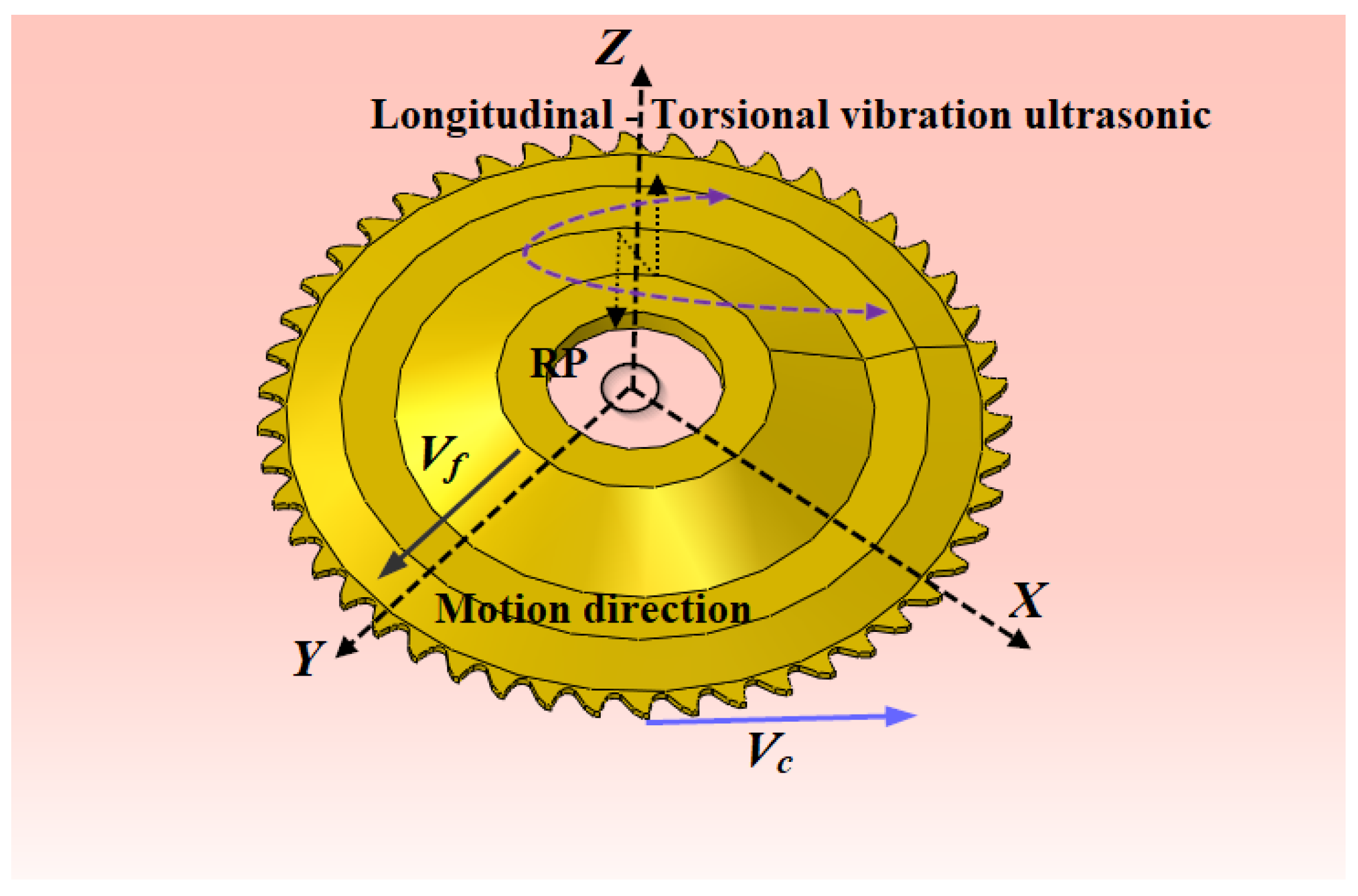
Rotary Ultrasonic Machining (RUM), based on longitudinal-torsional vibrations, is an advanced precision machining technique that relies on the coordinated superposition of several kinematic movements to improve cutting efficiency. It combines conventional tool rotation around the Z-axis at spindle speed n, responsible for the main cutting action, with longitudinal ultrasonic vibrations of frequency f and amplitude A, also oriented along the Z-axis (Figure 6). These sinusoidal oscillations induce rapid and periodic cycles of tool penetration and withdrawal, establishing intermittent contact at the tool–material interface. In the configuration studied, these longitudinal vibrations are coupled to a torsional component of the same frequency f and amplitude A, generating a complex three-dimensional helical motion. This movement results from the combination of a translation along the Y-axis at speed Vf and a rotation around the Z-axis (Figure 6), profoundly modifying the instantaneous trajectory of the cutting edge and the mechanisms of mechanical interaction. In the context of numerical simulations, a reference point (RP), positioned on the axis of revolution of the tool, is used to rigorously describe the combined movements of rotation, translation, and vibration (Figure 6). This kinematic formulation makes it possible to accurately characterize the contact conditions, the generation of cutting forces, and the influence of vibrational effects. It thus guarantees a realistic representation of the mechanical and dynamic phenomena involved, promoting a deep understanding of machining mechanisms and contributing to the optimization of the overall performance of the process.

4. Behavioral Model and Breaking Point Criterion

With anisotropic elastic behavior, Nomex paper exhibits variable mechanical properties depending on the direction of loading, combining high tensile strength with relatively limited compressive strength [33,34]. Given the minimal impact of multilayers on the machining of the NHC core, they are not considered in the numerical model. The thin walls of the structure are then described using a single-layer orthotropic approach, chosen for its ease of implementation. Because of its ease of execution, this technique is commonly used, and the mathematical equations describing the relationship between stresses and strains of an orthotropic material are presented below.
σ i j =   C       ε i j
σ 11 σ 22 σ 33 σ 23 σ 31 σ 12 = C   ε 11 ε 22 ε 33 ε 23 ε 31 ε 12 = C 11   C 12 C 13 0 0 0 C 21   C 22 C 23 0 0 0 C 31   C 32 C 33 0 0 0 0 0 0 C 12 0 0 0 0 0 0 C 23 0 0 0 0 0 0 C 31   ε 11 ε 22 ε 33 ε 23 ε 31 ε 12
We denote σij and εij the stress and strain tensors, respectively, and C the stiffness matrix, with i and j between 1 and 6 [38].
According to Kilchert’s analysis, the orthotropic mechanical properties of Nomex paper are summarized in Table 1 [39]. Damage assessment is based on the Tsai-Wu failure criterion, defined by the following equation [40]:
F 11 σ 11 2 + F 22 σ 22 2 + F 33 σ 33 2 +   F 44 σ 23 2 +   F 55 σ 13 2 +   F 66 σ 12 2 + 2   F 12 σ 11 σ 22 +   2   F 13 σ 11 σ 33 +   2   F 23 σ 22 σ 33 +   F 1 σ 11 + F 2 σ 22 +   F 3 σ 33 = 1
where Fi and Fij respectively denote the second and fourth order resistance tensors, defined as follows:
F 11 = 1 X t X c ; F 1 =   1 X t   1 X c ; F 22 = F 33 =   1 Y t Y c ; F 2 = F 3 = 1 Y t   1 Y c F 44 =   1 ( S 23 ) 2 ; F 55 = F 66 =   1 S 12 2 ; F 13 = F 12 =     1 2   F 11   F 12 ; F 23 =     1 2   F 22   F 33
The parameters X and Y indicate the limit stresses of the material in the longitudinal and transverse directions respectively, while S designates the limit shear stress given in Table 1. Reaching the failure criterion marks the beginning of progressive damage, resulting in a decrease in the stiffness matrix mentioned previously.
When the conditions of Equation (7) are satisfied, the Tsai-Wu criterion is applied to evaluate the damage of the stressed elements by comparing the effective stresses to the material strengths in each direction, and then decomposing it into stress components according to Equation (9) in order to determine the direction of damage and the associated loss of stiffness.
H 1 = F 1     σ 1 + F 11   σ 11 2 H 2 = F 2     σ 2 + F 22   σ 22 2 H 3 = F 3   σ 3 + F 33   σ 33 2 H 4 = F 44   σ 23 2 H 5 = F 55   σ 12 2 H 6 = F 66   σ 31 2
Once the Tsai-Wu criterion has been verified, the calculation and comparison of the Hk components allow the highest value to be retained as an indicator of the predominant damage mode, resulting in a decrease in the stiffness of the associated elastic modulus and the degradation of the corresponding characteristics, as specified in Table 2 [41,42].
The damage method adopted in this analysis is based on a subordinate approach consisting of reducing the stiffness of each elastic modulus from the moment fracture initiation. Within the framework of the Tsai-Wu criterion, damage is quantified using variables dk (k = 1, …, 6), as defined in Equations (9) and (10). The formulation of the stiffness degradation depends on the nature of the material and its mechanical behavior. For composite materials, this degradation is expressed by the following relationship [43]:
E i j = 1 d k   E i j 0
G i j = 1 d k   G i j 0
d k = 1 e x p   [   1 m   e   (   ε i j ε f i j ) m ]
where:
m denotes the softening parameter,
e represents the Euler number,
ε f i j   corresponds to the rupture strain determined according to the following expression.

5. Components of Cutting Force

During the tests, the Fx and Fy components of the cutting force, associated respectively with the X and Y axes, are measured using a KISTLER-9256C2 dynamometer, and then the average values in each direction are determined from the formulas below.
F x = 1 t 2 t 1   t 1 t 2 F C X   d t
F y = 1 t 2 t 1   t 1 t 2 F C Y   d t
In this formulation, Fx and Fy are the averages of the components of the cutting force along X and Y, and t1 and t2 respectively denote the initial and final times of the cut.

6. Results and Discussion

6.1. Calibration of the Coefficient of Friction

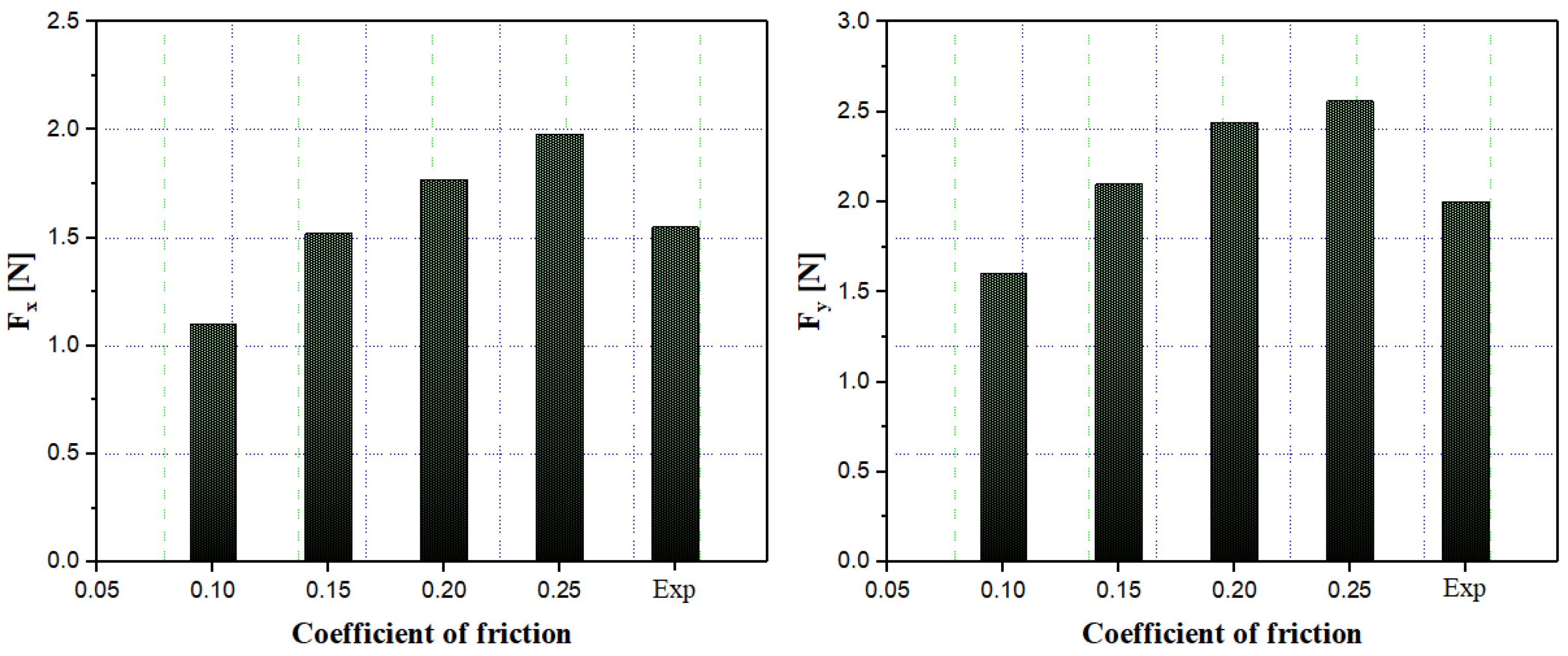
The coefficient of friction is a key parameter in ultrasonic vibration-assisted milling, as it governs the interaction mechanisms between the tool and the workpiece. A constant friction coefficient was assumed in this study to simplify the modeling while remaining representative of the actual tribological behavior. This coefficient was identified by comparing simulated and experimental forces, ensuring an accurate reproduction of the tool–workpiece interface conditions during ultrasonic milling. It conditions chip formation and directly influences the amplitude of cutting forces, thus impacting the overall performance of the process. To this end, four values of the coefficient of friction, ranging from 0.10 to 0.25, were studied. Its identification was carried out by comparing the forces obtained from the numerical simulation with those measured experimentally during the machining of a Nomex honeycomb structure under longitudinal ultrasonic vibrations, for operating conditions of 500 rpm and 3000 mm/min. Analysis of the results presented in Figure 7 shows that the force components Fx and Fy increase monotonically with the friction coefficient, reflecting an intensification of interactions at the tool–workpiece interface as well as an increase in adhesion phenomena. For low values (0.10–0.15), the simulated forces remain lower than the experimental measurements, indicating an underestimation of energy dissipation due to friction. Conversely, when the friction coefficient exceeds 0.25, the calculated cutting force components surpass the experimental values, revealing an overestimation of tribological effects. The best agreement with experimental results is obtained for a friction coefficient close to 0.20, at which point the discrepancies in Fx and Fy are minimized. This value can therefore be retained as a representative friction coefficient in the process modeling, because it faithfully reproduces the real tribological conditions at the tool-workpiece interface during ultrasonic milling of the Nomex honeycomb structure.

6.2. Validation of the Numerical Model

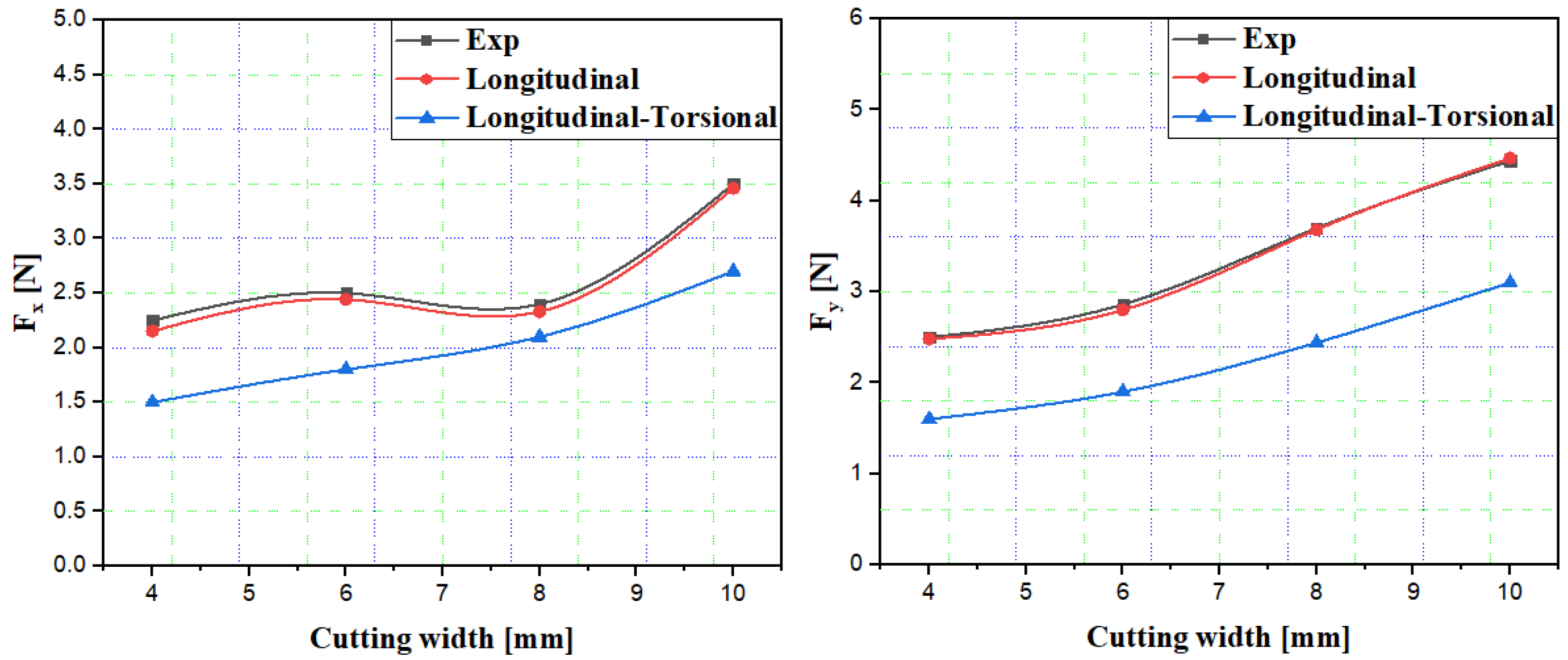
Figure 8 illustrates the influence of the cutting width on the components of the cutting forces Fx and Fy during the milling of a Nomex honeycomb structure. The experimental results are compared to predictions from simulations performed under longitudinal and longitudinal-torsional ultrasonic vibrations. For this purpose, four cutting widths (4, 6, 8, and 10 mm) were studied, while maintaining a constant rotational speed of 500 rpm (Figure 8). Overall, increasing the cutting width causes a significant increase in effort, due to the increased volume of material involved and the contact area between the tool and the material. From an experimental standpoint, the tangential force Fx increases from approximately 2.20 N to 3.45 N between 4 and 10 mm, representing a progression of about 57%, with a slight decrease of approximately 6% between 6 and 8 mm before a sharp increase at 10 mm. The normal component Fy increases from 2.45 N to 4.45 N over the same range, representing an increase of approximately 82%, indicating that the cutting width influences the tool’s penetration resistance more than the tangential force. The simulation with longitudinal vibration shows very good agreement with experimental results, with discrepancies generally remaining below 3% for Fx and 2% for Fy, thus confirming the model’s validity for these machining conditions. In the case of cutting assisted by longitudinal ultrasonic vibration, the cutting mechanism relies on an alternating axial movement of the tool, which causes successive phases of contact and separation with the material. This phenomenon reduces the effective contact time, decreases friction, and facilitates the brittle fragmentation of composite walls, which is particularly advantageous for cellular structures susceptible to crushing and delamination. Conversely, longitudinal-torsional assistance allows for an even further reduction of cutting forces. For Fx, the reduction compared to the longitudinal mode is approximately 30% at 4 mm, 27% at 6 mm, 9% at 8 mm, and 21% at 10 mm, while for Fy the reduction reaches approximately 35% at 4 mm and exceeds 30% for larger cutting widths. In this combined mode, the superposition of torsional vibration on top of longitudinal vibration generates a helical movement of the cutting edge, partially transforming the shear into oblique micro-shears. This mechanism promotes the initiation and controlled propagation of cracks in composite walls, improves debris removal, and limits cell detachment or crushing. Thus, longitudinal ultrasonic cutting already offers a significant reduction in stress and damage, but the longitudinal-torsional configuration presents additional advantages for machining composite structures: greater reduction of forces, improved edge integrity, reduced delamination, and extended tool life. Ultimately, the cutting width is a determining parameter in the generation of forces during ultrasonic milling of Nomex, while longitudinal-torsional assistance appears to be the most efficient solution for optimizing the machining quality of composite honeycomb structures.

6.3. Ultrasonic Vibration Analysis on Bonding Wear

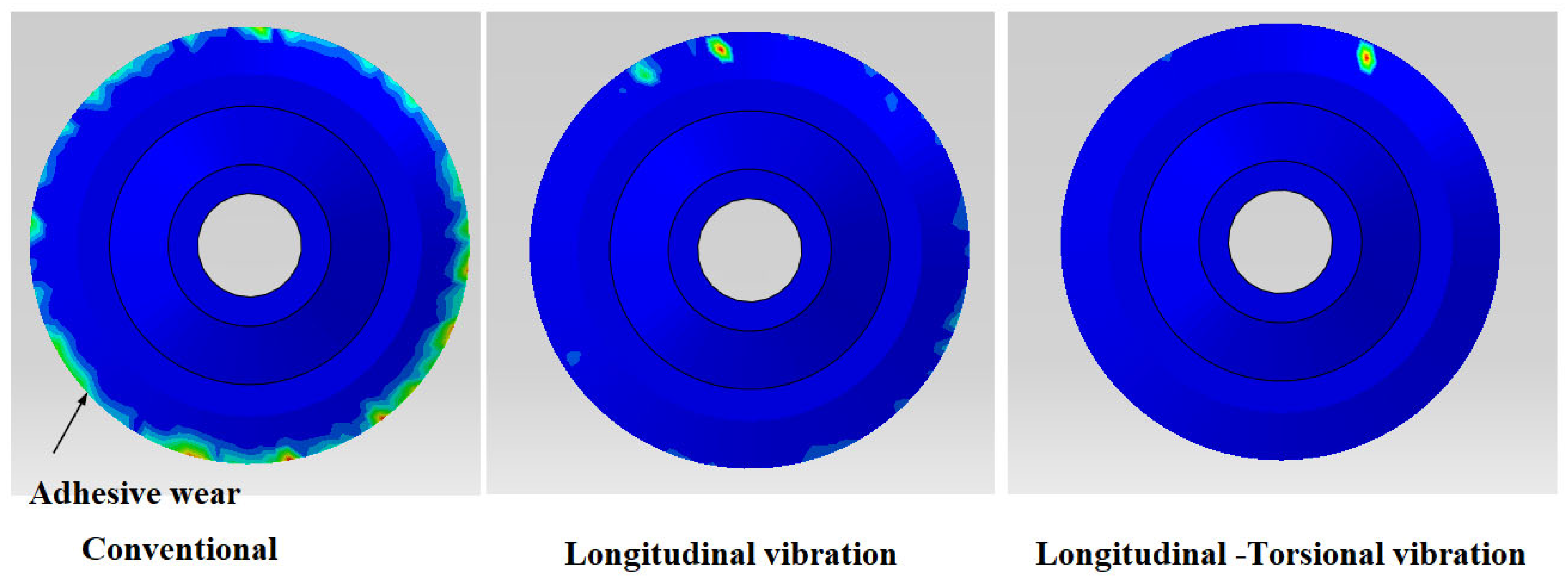
Analyzing tool wear caused by adhesion during the milling of composite structures is essential for understanding the progressive degradation of cutting performance and optimizing tool life. This wear mechanism, highly dependent on the thermomechanical conditions at the tool–material interface, is particularly critical in the case of polymer matrix composites. Indeed, the matrix can soften under the effect of localized heating, then adhere to the flank surface and near the cutting edge. This adhesion alters the effective geometry of the tool, disrupts shearing, increases cutting forces, and promotes additional friction. Consequently, bonded wear leads to several direct disadvantages on cutting quality: increased roughness, the appearance of burrs, material tear-off, surface finish degradation, and an increased risk of composite-specific defects such as delamination, matrix cracking, or irregular fiber breakage. Thus, studying this type of wear not only allows us to diagnose the origin of defects, but also to propose more stable and reliable cutting strategies for the industrial composites machining. To strengthen the correlation with numerical simulations, experimental measurements were performed to quantify tool wear and material adhesion. Tool edges were examined using optical microscopy (Keyence VHX-6000) and scanning electron microscopy (Zeiss EVO) to measure edge rounding, micro-chipping, and thickness of the adhered layer. Material accumulation on the flank face was evaluated by image analysis (ImageJ, version 2015) applied to high-resolution optical images, while surface quality of the machined composite was assessed using a 3D optical profilometer (Alicona Infinite Focus) to obtain roughness parameters (Ra, Rz). This combination of techniques provides a direct link between the observed wear patterns, the accumulation of material, and their effects on surface integrity, allowing for better validation of the numerical models and improving the reproducibility of results. In this context, this section presents a numerical study aimed at evaluating the influence of the milling mode on bond wear, under constant cutting conditions, namely a feed rate fixed at 3000 mm/min and a spindle speed of 500 rpm. Three configurations are compared: conventional milling, milling assisted by longitudinal vibration, and milling assisted by longitudinal-torsional vibration. The wear maps in Figure 9 reveal significant variations in the distribution and intensity of bonding depending on the kinematics applied to the tool. The results show that in conventional milling, bond wear is the most pronounced. It manifests as a larger adhesion zone, primarily located on the active periphery of the tool, resulting in almost continuous contact between the tool and the workpiece. This method offers the advantage of simple kinematics and direct industrial implementation, but it remains unfavorable for composites because the continuous contact increases interfacial temperature and frictional stresses. This results in more stable adhesion of the material to the clearance surface, which accelerates wear, damages the cutting edge, and degrades cut quality. The introduction of longitudinal vibrations significantly reduces wear caused by adhesion. Wear zones become more localized and generally less intense, indicating a decrease in adhesion and an improvement in tribological behavior. This phenomenon is explained by the onset of intermittent contact: high-frequency vibrations cause periodic micro-separations between the tool and the workpiece, reducing the effective contact time, and therefore the heat generated and the probability of the formation of an adhesive layer. The main advantage of this mode is the reduction of average forces and improved chip fragmentation, which contributes to a cleaner cut and better stability. However, a drawback may remain in the form of localized points of residual adhesion, particularly in areas where instantaneous pressure remains high or where micro-chip evacuation is insufficient. Finally, the longitudinal-torsional mode appears to be the most effective for limiting wear due to adhesion. The corresponding mapping shows a nearly uniform surface with very low wear intensity, as adhesion is reduced to an extremely localized area. This improvement results from the coupling of two complementary effects: longitudinal vibration reduces continuous contact, while the torsional component introduces alternating micro-shearing that prevents the stabilization of particles stuck to the tool. Thus, the actual contact area is reduced, sliding friction decreases, and local temperature is better controlled. The major advantage of this method is therefore a significant reduction in sticking, better preservation of the cutting edge, and consequently, an expected improvement in cutting quality. In summary, the numerical study confirms that the milling method strongly influences bond wear under identical cutting conditions (3000 mm/min, 500 rpm). Conventional milling, although simple, promotes significant bonding and a more rapid degradation of cut quality. Longitudinal vibrations significantly reduce wear through intermittent contact and improved fragmentation, while maintaining relative ease of implementation compared to hybrid modes. The longitudinal-torsional mode offers the best tribological performance and tool protection, making it a particularly suitable solution for machining composites, despite its higher technological complexity.

6.4. Influence of Tool Geometry on Material Accumulation in Vibration-Assisted Milling

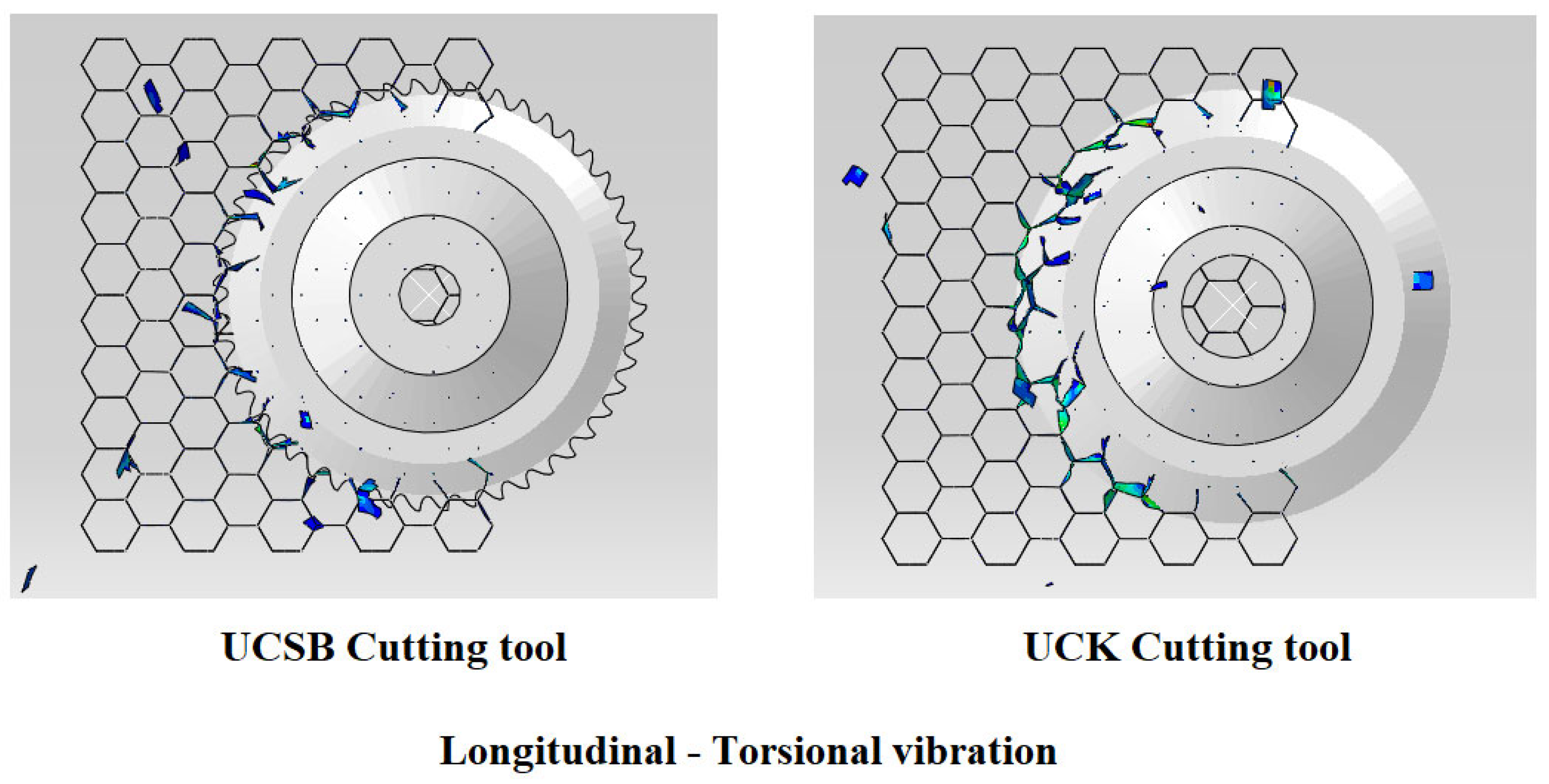
Analyzing material buildup on the tool (chip deposits/adhesion, formation of a built-up layer) is particularly relevant when milling composite structures, as it provides a direct indicator of the tribological conditions at the tool-material interface. This phenomenon is generally favored by the combination of high contact pressure, significant friction, and localized heating, which softens the polymer matrix and facilitates its transfer to the flank surface and near the cutting edge. The accumulation of material presents several major disadvantages on the quality of cutting: modification of the effective cutting geometry (edge blunted by the adherent layer), increased forces, shear instability, appearance of burrs and tears, degradation of the surface condition and aggravation of defects typical of composites (irregular breakage of fibers, local delamination). Thus, quantifying and comparing these deposits allows us to identify the actual behavior of the tool in use and to guide the geometric and technological choices of the tool. In this context, this section presents a numerical study comparing the material accumulation phenomenon for two cutting tools (UCSB and UCK). The simulations were performed under identical cutting conditions, namely a rotational speed of 5000 rpm and a feed rate of 3000 mm/min, while using the same milling mode assisted by longitudinal-torsional vibrations. The results in Figure 10 highlight a marked difference in the quantity and distribution of deposits around the active cutting zone. For the UCK tool, a more pronounced presence of accumulated fragments is observed, with particles and clusters visible in the immediate vicinity of the tool and along the contact zone. This trend suggests that, despite the vibratory assistance (which generally reduces continuous contact), the UCK tool locally maintains conditions favorable to adhesion: areas of high instantaneous pressure, more pronounced slippage on the bevel, or less efficient evacuation of generated fragments. As a result, the adhesive layer can form more easily, which penalizes cutting stability and increases the risk of progressive edge degradation by intermittent detachment of deposits (sticking-unsticking), a phenomenon known to accelerate damage and variability of the surface condition. Conversely, the UCSB tool exhibits a generally lower and more discontinuous accumulation of material. The deposits appear fewer and less extensive, indicating a more stable tool–material interface in this same vibrational mode. This improvement can be interpreted as a better ability of the UCSB tool to limit adhesion, either through a more favorable mechanical interaction (more efficient shear, reduction of actual friction), or through better evacuation of fragments in the vicinity of the edge, reducing the probability that micro-chips and the softened matrix temporarily weld to the flank surface. In the context of the longitudinal-torsional mode, alternating micro-shearing normally prevents the stabilization of stuck particles; the fact that the UCSB benefits more from this effect suggests that it more effectively exploits vibratory kinematics to “unstick” nascent deposits and maintain a cleaner active edge. From the point of view of advantages and disadvantages, the UCK tool can exhibit energetic cutting behavior (significant fragmentation), but its main disadvantage, under these conditions, is a higher sensitivity to material accumulation, which can lead to a more rapid degradation of cutting quality (burrs, tearing, higher roughness) and to a progressive instability of forces. In contrast, the UCSB tool stands out for better adhesion control and reduced accumulation, which is a direct advantage for process stability, edge retention and surface condition regularity. Its potential drawback may lie in a geometric or technological compromise (depending on the actual design of the tool) which could limit certain extreme regimes, but, under the conditions studied and under longitudinal-torsional vibrations, it appears more favorable for minimizing deposits and preserving the quality of the cut. In summary, under identical conditions and the same mode of milling assisted by longitudinal-torsional vibrations, the comparison highlights that the design of the tool remains crucial: vibration assistance reduces adhesion overall, but the UCSB tool shows a better ability to prevent the accumulation of material, which results in a more controlled tribological interaction and, consequently, a superior potential in terms of durability and cutting quality of composite structures. In this context, the use of an orthotropic single-layer material model with a progressive damage law based on the Tsai-Wu criterion provides an additional perspective to analyze and predict tool performance. By accounting for directional material properties and the evolution of local damage, such a model can simulate how the composite fragments and how chips form under cutting. This allows a deeper understanding of why the UCSB tool limits material accumulation more effectively and maintains better cutting stability, while the UCK tool experiences more pronounced fragmentation and adhesion. The model thus has strong potential for guiding tool geometry and process parameters to optimize chip evacuation, reduce edge degradation, and improve overall cutting performance in composite milling.

6.5. Effect of Ultrasonic Amplitude on Longitudinal-Torsional Milling Performance

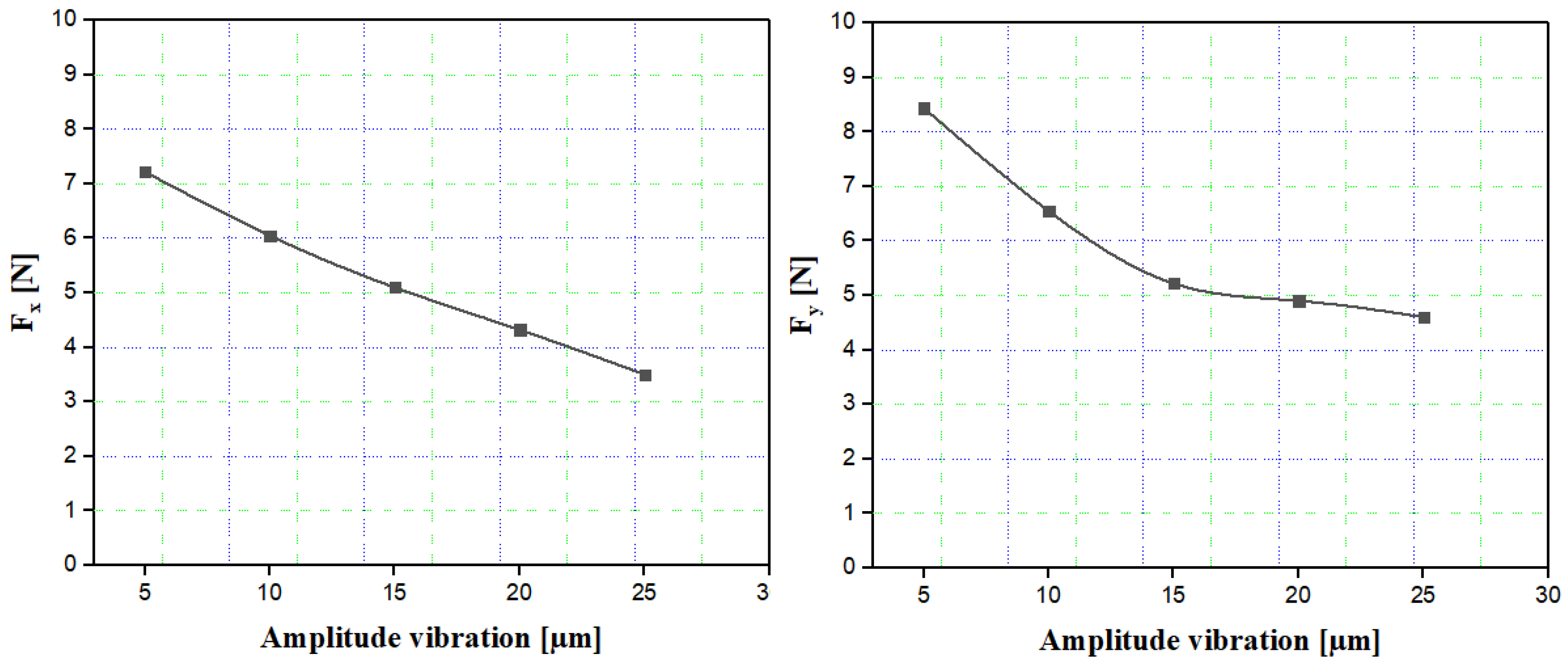
Analyzing the influence of the amplitude of longitudinal-torsional vibrations on cutting forces is an essential indicator for evaluating the effectiveness of ultrasonic-assisted milling in the machining of composite structures. The introduction of coupled vibration, combining axial and torsional motion, profoundly alters the cutting kinematics by establishing intermittent contact accompanied by alternating micro-shearing at the tool-material interface. This mechanism simultaneously reduces the actual contact area, frictional stresses, and generated heat, resulting in a significant decrease in cutting forces and improved process stability. The influence of ultrasonic vibration amplitude on the cutting force components was examined under constant cutting conditions, fixed at a rotational speed of 500 rpm and a feed rate of 3000 mm/min. As illustrated by the curves in Figure 11, increasing the vibration amplitude from 5 to 25 µm leads to a significant reduction in the cutting force components. The Fx component decreases from approximately 7.2 N to 3.5 N, a reduction of about 51%, reflecting the increasing effectiveness of intermittent contact, which limits adhesion and facilitates the fragmentation of the material into micro-chips. As for the Fy component, it decreases from approximately 8.4 N to 4.5 N, corresponding to a reduction of about 46%, confirming the general trend observed for both force components. For an intermediate amplitude of 15 µm, the reduction already reaches 30 to 35%, suggesting that most of the gain is achieved at medium amplitudes. Conversely, at low amplitudes of 5 µm, the effect of vibrations remains limited due to the maintenance of partially continuous tool–workpiece contact, which explains the still high force levels. When the amplitude reaches larger values (20–25 µm), the disengagement phase becomes dominant, significantly reducing the effective contact time and therefore the frictional stresses. However, the slope of the force reduction tends to stabilize at the highest amplitudes, suggesting the existence of an optimal threshold beyond which increasing the amplitude provides only a small additional gain (less than 10%). The choice of the 5–25 µm amplitude range is motivated by the capabilities of the THU Ultrasonic 850 device, which allows stable operation within this interval, as well as by prior studies indicating that amplitudes within this range are most effective for polymer–matrix composites like Nomex. Exploring amplitudes below 5 µm would result in insufficient intermittent contact, limiting the beneficial reduction in cutting forces, whereas amplitudes above 25 µm could generate excessive tool vibration, risking dynamic instabilities, increased wear, or even tool damage. This justification ensures that the selected range represents both practical operational limits and the optimal window for process efficiency. From the point of view of advantages, the longitudinal-torsional mode therefore allows an overall reduction of cutting forces that can exceed 45 to 50%, which results in a decrease in tool wear, an improvement in surface quality and a limitation of typical composite defects such as delamination and fiber pull-out. It also promotes a more stable cut by reducing sticking and sliding friction. However, its main drawback lies in the complexity of the vibratory device, requiring precise control of amplitudes and mode coupling to avoid dynamic instabilities or excessive stress on the tool. In conclusion, increasing the amplitude of longitudinal-torsional vibrations leads to a significant reduction in cutting forces, reaching approximately 50% between the minimum and maximum amplitudes studied. These results confirm the effectiveness of the hybrid vibration mode for machining composite materials and highlight the importance of choosing an optimal amplitude to obtain the best compromise between cutting performance, tool durability and cutting quality.

6.6. Analysis of Cutting Forces as a Function of Vibration Frequency

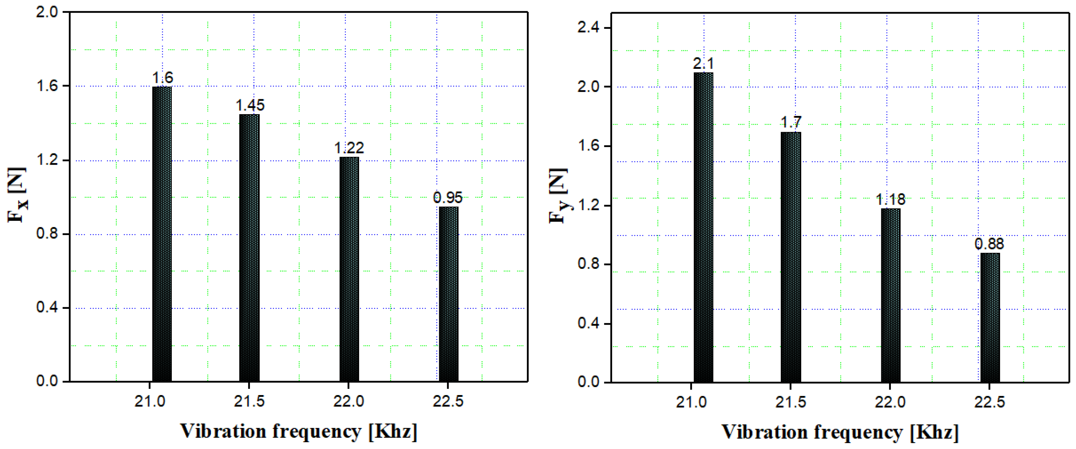
Analyzing the influence of longitudinal-torsional vibration frequency on cutting forces is a key parameter for optimizing ultrasonic-assisted milling of composite structures. Indeed, vibration frequency directly affects the dynamics of the tool–material contact, modifying the duration of successive contact and separation phases, as well as the intensity of micro-shearing at the interface. Increasing the frequency leads to a higher number of impacts per unit of time, which promotes more efficient material fragmentation, reduces sliding friction, and limits adhesion phenomena responsible for increased cutting forces. In this study, the influence of vibration frequency on the components of the cutting force was examined under fixed cutting conditions of 500 rpm for the rotational speed and 3000 mm/min for the feed rate. The results presented in Figure 12 show a clear decrease in the components of the cutting force as the frequency increases from 21 kHz to 22.5 kHz. For the Fx component, the value decreases from approximately 1.6 N to 0.95 N, representing a reduction of about 41%. A progressive decrease in effort is observed starting at 21.5 kHz, with a value of approximately 1.45 N, a reduction of about 9% compared to the initial value. This trend is confirmed at 22 kHz, where the effort reaches approximately 1.22 N, corresponding to an overall decrease of about 24%. This trend indicates that the beneficial effect of vibration becomes significant at intermediate frequencies, where intermittent contact begins to dominate the cutting regime. The second component, Fy, exhibits similar behavior but with higher initial values. The force decreases from approximately 2.1 N to 0.88 N, corresponding to a reduction of about 58%, reflecting an even greater sensitivity to increased vibration frequency. At 21.5 kHz, the reduction reaches approximately 19%, while at 22 kHz it exceeds 43%, confirming the increasing efficiency of the high-frequency longitudinal-torsional mode. The selected frequency range of 21–22.5 kHz is based on the operational limits of the experimental setup and previous studies demonstrating optimal tool–material interaction for composite milling within this interval. Frequencies below 21 kHz would reduce the number of micro-separation events, limiting the effect of intermittent contact, while frequencies above 22.5 kHz could induce resonance or excessive vibrational stresses on the tool and machine components. Thus, this range ensures both safe operation and effective reduction of cutting forces, providing a representative evaluation of the process. This significant reduction is explained by the increased number of tool-workpiece disengagement cycles, which limits contact time, reduces heat generation, and improves microchip removal. From an advantage standpoint, increasing the vibration frequency allows for a significant reduction in cutting forces, reaching 40 to 60%, which helps to decrease tool wear, improve surface quality, and reduce machining defects in composites such as delamination or fiber pull-out. It also promotes greater process stability by limiting sticking and friction phenomena. Ultimately, increasing the frequency of longitudinal-torsional vibrations leads to a marked decrease in cutting forces, confirming that frequency is a key parameter for optimizing ultrasonic-assisted milling. Identifying an optimal frequency allows for a compromise between cutting efficiency, process stability and tool durability, which is essential for high-performance machining of composite materials.

6.7. Influence of the Frequency of Longitudinal-Torsional Vibrations on the Formation of Material Clusters at the Tool-Chip Interface

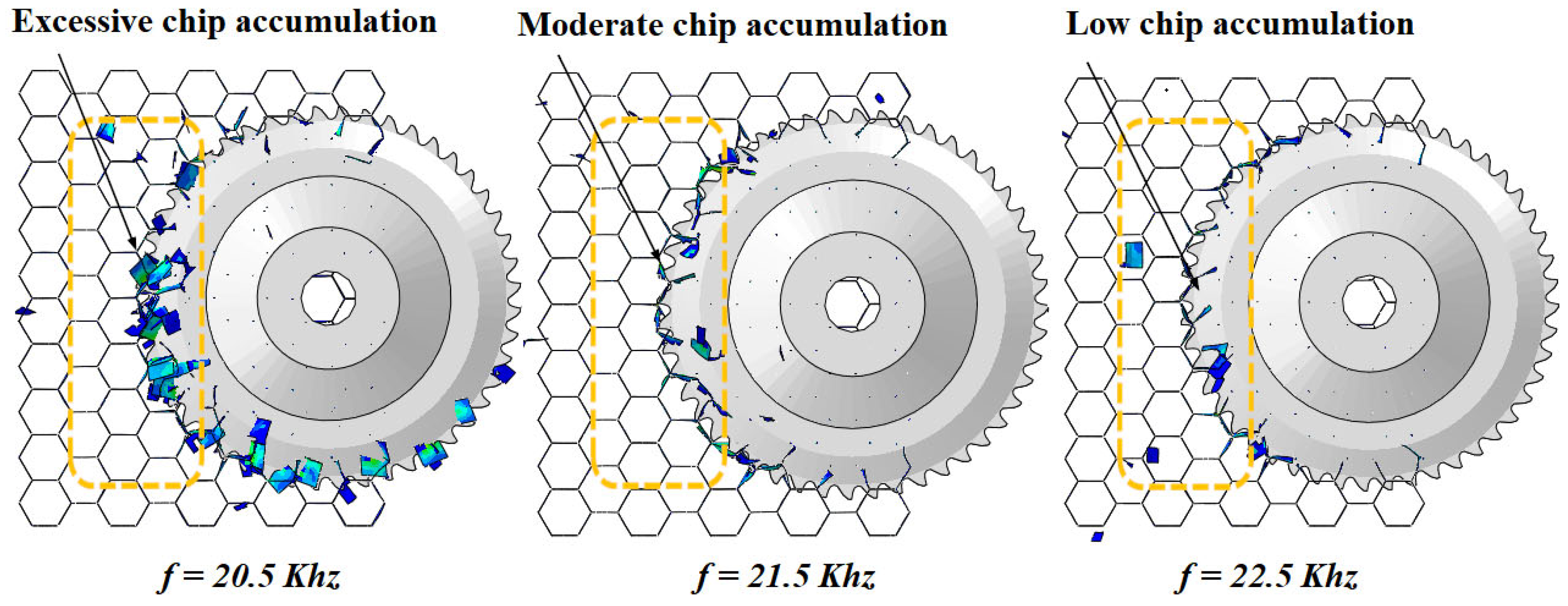
Analyzing the formation of accumulations of material adhered to the cutting tool represents a major challenge for understanding wear mechanisms, tribological degradation and alteration of surface integrity in machining. Chip accumulation in front of the cutting edge alters local conditions by increasing mechanical stresses, thermal stresses, and tool–material adhesion. This unstable intermediate zone disrupts chip flow, promotes the formation of a built-up edge, and causes fluctuations in cutting forces, which degrades surface quality and reduces tool life. The formation of aggregates results from complex interactions between tribological, thermal, and mechanical effects. Prolonged contact promotes plastic adhesion, particularly with high-speed steel tools that have a strong chemical affinity for certain materials. Localized temperature increases lead to thermal softening, facilitating deformation and agglomeration of the material. After all, a fragmentation that lasts a long time and continues to be encrypted, tandis that the fortes contraintes compressives accentuent the compaction. In this context, longitudinal-torsional ultrasonic vibration assistance emerges as a particularly promising approach for stabilizing the cutting process and limiting the formation of material buildup. This section presents an analysis of chip accumulation as a function of vibration frequency, under fixed cutting conditions of 3000 mm/min for the feed rate and 500 rpm for the spindle speed, using an HSS/USSB tool. The results presented in Figure 13 highlight the crucial influence of vibration frequency on the dynamics of cluster formation, by modifying the mechanisms of adhesion, chip fragmentation, and tool–material interaction. At low frequencies (20.5 kHz), the observed accumulation is excessive, indicating that the effective vibration amplitude is insufficient to establish a sufficiently pronounced intermittent contact regime. The cutting process then remains almost continuous, promoting chip adhesion and wrapping in front of the tool. At an intermediate frequency (21.5 kHz), chip accumulation becomes moderate, reflecting the gradual establishment of an intermittent cutting regime. The longitudinal component of the vibrations induces phases of periodic separation between the tool and the material, reducing normal forces and contact pressure, while the torsional component introduces an oscillatory tangential movement that fragments the chips and limits their adhesion. This synergy improves chip evacuation and reduces material fragment compaction in the cutting zone. At high frequencies (22.5 kHz), accumulation becomes minimal, demonstrating the maximum efficiency of the longitudinal-torsional mode in minimizing chip formation. The highly intermittent contact considerably reduces the tool-material interaction time, decreases friction and lowers the local temperature, thus preventing the adhesion and thermal softening mechanisms responsible for agglomeration. Furthermore, the increased fragmentation of the chips produces finer, more discontinuous particles that are easily removed from the cutting zone. This condition corresponds to a stable cutting regime characterized by reduced cutting forces, improved surface quality, and a decreased tool wear rate. Thus, increasing the vibration frequency appears to be a key parameter for controlling the formation of material buildup in longitudinal-torsional vibration-assisted cutting. The combined optimization of frequency and vibration mode makes it possible to transform a cutting regime dominated by adhesion and clogging into one dominated by fragmentation and efficient chip evacuation, significantly improving the overall performance of the machining process.

7. Conclusions

This work has demonstrated the relevance of ultrasonic vibration assistance, whether purely longitudinal or combined longitudinal-torsional, in the milling of honeycomb structures in Nomex. The three-dimensional model developed under Abaqus/Explicit made it possible to faithfully reproduce the behavior of the material during machining and to evaluate the influence of vibrations on several key indicators, including cutting forces, chip generation mechanisms and the surface finish obtained. The main conclusions can be summarized as follows:
  • The coefficient of friction influences the cutting forces and, with an optimal value of approximately 0.20, ensures good agreement between simulation and experiment.
  • The results show that increasing the cutting width leads to a significant increase in forces, while ultrasonic vibrations—particularly in longitudinal-torsional mode—effectively reduce them, making this combined mode the most efficient solution for minimizing forces and improving machining quality.
  • The results show that the longitudinal-torsional mode effectively reduces adhesion wear by combining intermittent contact and alternating micro-shearing, thereby preserving cutting edge integrity and improving overall process stability.
  • The modeling shows that the geometry of the tool remains a determining parameter, even under vibration assistance, with the UCSB profile more effectively exploiting the longitudinal-torsional kinematics to limit adhesion and improve durability as well as machining regularity.
  • The results show that increasing the vibration amplitude up to 25 µm reduces cutting forces by up to 50%, with a significant gain from 15 µm, highlighting the existence of an optimal amplitude to maximize process efficiency.
  • The results show that increasing the vibration frequency leads to a reduction in cutting forces of 40 to 60%, confirming that it is an essential lever for optimizing tribological stability and overall performance of ultrasonic milling.
  • The results show that frequency optimization in longitudinal-torsional mode transforms the cutting regime, replacing adhesion and clogging with controlled fragmentation and efficient chip evacuation, thus reducing agglomerate formation and sustainably stabilizing the machining process.
  • Despite its superior cutting performance, the longitudinal-torsional (LT) vibration mode is more complex to implement than the simple longitudinal mode. It requires precise system design, stable vibration coupling, and careful cost–benefit evaluation for industrial adoption.

Author Contributions

O.B. performed analysis, methodology, interpreted data and results, and was a major contributor to writing the manuscript. T.Z. performed analysis, methodology, interpreted data and results, and was a major contributor to writing the manuscript. A.A. performed analysis, interpreted data and results, and was a major contributor to writing the manuscript, investigation. M.N. contributed to the supervision, methodology, and investigation; performed analysis, interpreted data and results, and was a contributor to writing the manuscript. W.D. interpreted results and major contributor to writing the manuscript. M.A. interpreted results and major contributor to writing the manuscript. J.-E.S. interpreted results and was a major contributor to writing the manuscript. M.A. interpreted results and major contributor to writing the manuscript. M.B. interpreted results and was a major contributor to writing the manuscript. All authors have read and agreed to the published version of the manuscript.

Funding

This research received no external funding.

Institutional Review Board Statement

Not applicable.

Informed Consent Statement

For studies not involving humans.

Data Availability Statement

The original contributions presented in this study are included in the article. Further inquiries can be directed to the corresponding author.

Conflicts of Interest

The authors declare no conflicts of interest.

References

  1. Haq, S.U.; Raju, G.G. DC breakdown characteristics of high temperature polymer films. IEEE Trans. Dielectr. Electr. Insul. 2006, 13, 917. [Google Scholar]
  2. Yang, C.Q.; He, Q.; Lyon, R.E.; Hu, Y. Investigation of the flammability of different textile fabrics using micro scale combustion calorimetry. Polym. Degrad. Stab. 2010, 95, 108–115. [Google Scholar] [CrossRef]
  3. Foo, C.C.; Chai, G.B.; Seah, L.K. Mechanical properties of Nomex material and Nomex honeycomb structure. Compos. Struct. 2007, 80, 588–594. [Google Scholar] [CrossRef]
  4. Castanie, B.; Bouvet, C.; Ginot, M. Review of composite sandwich structure in aeronautic applications. Compos. Part C Open Access 2020, 1, 100004. [Google Scholar]
  5. Botelho, E.C.; Silva, R.A.; Pardini, L.C.; Rezende, M.C. A review on the development and properties of continuous fiber/epoxy/aluminum hybrid composites for aircraft structures. Mater. Res. 2006, 9, 247–256. [Google Scholar] [CrossRef]
  6. Xu, J.; Wang, C.; Feng, P.; Jiang, E.; Feng, F. Meso-scale cracks initiation of Nomex honeycomb composites in orthogonal cutting with a straight blade cutter. Compos. Sci. Technol. 2023, 223, 109914. [Google Scholar] [CrossRef]
  7. Hu, X.P.; Chen, S.Y.; Zhang, Z.C. Research on curved surface forming of nomex honeycomb material based on ultrasonic NC cutting. Adv. Mater. Res. 2012, 538, 1377–1381. [Google Scholar] [CrossRef]
  8. Zarrouk, T.; Salhi, J.-E.; Atlati, S.; Nouari, M.; Salhi, M.; Salhi, N. Modeling and numerical simulation of the chip formation process when machining Nomex. Environ. Sci. Pollut. Res. 2022, 29, 98–105. [Google Scholar] [CrossRef]
  9. Zarrouk, T.; Salhi, J.-E.; Nouari, M.; Salhi, M.; Atlati, S.; Salhi, N.; Makich, H. Analysis of friction and cutting parameters when milling honeycomb composite structures. Adv. Mech. Eng. 2021, 13, 16878140211034841. [Google Scholar] [CrossRef]
  10. Zarrouk, T.; Nouari, M.; Makich, H. Simulated Study of the Machinability of the Nomex Honeycomb Structure. J. Manuf. Mater. Process. 2023, 7, 28. [Google Scholar] [CrossRef]
  11. Li, Z.; Yuan, S.; Ma, J.; Shen, J.; Batako, A.D. Study on the surface formation mechanism in scratching test with different ultrasonic vibration forms. J. Mater. Process. Technol. 2021, 294, 117108. [Google Scholar] [CrossRef]
  12. Yang, Z.; Zhu, L.; Zhang, G.; Ni, C.; Lin, B. Review of ultrasonic vibration-assisted machining in advanced materials. Int. J. Mach. Tools Manuf. 2020, 156, 103594. [Google Scholar] [CrossRef]
  13. Jain, A.K.; Pandey, P.M. Modeling of un-deformed chip thickness in RUM process and study of size effects in μ-RUM. Ultrasonics 2017, 77, 1–16. [Google Scholar] [CrossRef] [PubMed]
  14. Sun, L.; Liao, W.; Zheng, K.; Tian, W.; Liu, J.; Feng, J. Stability analysis of robotic longitudinal-torsional composite ultrasonic milling. Chin. J. Aeronaut. 2022, 35, 249–264. [Google Scholar] [CrossRef]
  15. Liu, J.; Jiang, X.; Han, X.; Zhang, D. Influence of parameter matching on performance of high-speed rotary ultrasonic elliptical vibration-assisted machining for side milling of titanium alloys. Int. J. Adv. Manuf. Technol. 2019, 101, 1333–1348. [Google Scholar] [CrossRef]
  16. Zhang, M.; Zhang, D.; Geng, D.; Shao, Z.; Liu, Y.; Jiang, X. Effects of tool vibration on surface integrity in rotary ultrasonic elliptical end milling of Ti–6Al–4V. J. Alloys Compd. 2020, 821, 153266. [Google Scholar] [CrossRef]
  17. Wang, J.; Zhang, J.; Feng, P.; Guo, P. Damage formation and suppression in rotary ultrasonic machining of hard and brittle materials: A critical review. Céram. Int. 2018, 44, 1227–1239. [Google Scholar] [CrossRef]
  18. Wang, J.; Feng, P.; Zhang, J. Reducing edge chipping defect in rotary ultrasonic machining of optical glass by compound step-taper tool. J. Manuf. Process. 2018, 32, 213–221. [Google Scholar] [CrossRef]
  19. Zha, H.; Feng, P.; Zhang, J.; Yu, D.; Wu, Z. Material removal mechanism in rotary ultrasonic machining of high-volume fraction SiCp/Al composites. Int. J. Adv. Manuf. Technol. 2018, 97, 2099–2109. [Google Scholar] [CrossRef]
  20. Dong, S.; Liao, W.; Zheng, K.; Liu, J.; Feng, J. Investigation on exit burr in robotic rotary ultrasonic drilling of CFRP/aluminum stacks. Int. J. Mech. Sci. 2019, 151, 868–876. [Google Scholar] [CrossRef]
  21. An, Q.; Dang, J.; Ming, W.; Qiu, K.; Chen, M. Experimental and Numerical Studies on Defect Characteristics During Milling of Aluminum Honeycomb Core. J. Manuf. Sci. Eng. 2019, 141, 031006. [Google Scholar] [CrossRef]
  22. Abbadi, A.; Tixier, C.; Gilgert, J.; Azari, Z. Experimental study on the fatigue behaviour of honeycomb sandwich panels with artificial defects. Compos. Struct. 2015, 120, 394–405. [Google Scholar] [CrossRef]
  23. Meruane, V.; del Fierro, V. An inverse parallel genetic algorithm for the identification of skin/core debonding in honeycomb aluminium panels. Struct. Control Health Monit. 2015, 22, 1426–1439. [Google Scholar] [CrossRef]
  24. Wang, J.; Feng, P.; Zhang, J.; Guo, P. Experimental study on vibration stability in rotary ultrasonic machining of ceramic matrix composites: Cutting force variation at hole entrance. Ceram. Int. 2018, 44, 14386–14392. [Google Scholar] [CrossRef]
  25. Wang, H.; Cong, W.; Ning, F.; Hu, Y. A study on the effects of machining variables in surface grinding of CFRP composites using rotary ultrasonic machining. Int. J. Adv. Manuf. Technol. 2018, 95, 3651–3663. [Google Scholar] [CrossRef]
  26. Yuan, S.; Li, Z.; Zhang, C.; Guskov, A. Research into the transition of material removal mechanism for C/SiC in rotary ultrasonic face machining. Int. J. Adv. Manuf. Technol. 2018, 95, 1751–1761. [Google Scholar] [CrossRef]
  27. Chen, X.; Wang, H.; Hu, Y.; Zhang, D.; Cong, W.; Burks, A.R. Rotary ultrasonic machining of CFRP compo-sites: Effects of machining variables on workpiece delamination. In Proceedings of the ASME 2019 14th International Manufacturing Science and Engineering Conference, Erie, PA, USA, 10–14 June 2019; The American Society of Mechanical Engineers: New York, NY, USA, 2019; Volume 2, p. V002T03A051. [Google Scholar]
  28. Li, C.; Piao, Y.; Meng, B.; Hu, Y.; Li, L.; Zhang, F. Phase transition and plastic deformation mechanisms induced by self-rotating grinding of GaN single crystals. Int. J. Mach. Tools Manuf. 2022, 172, 103827. [Google Scholar] [CrossRef]
  29. Sandá, A.; Sanz, C. Rotary ultrasonic machining of ZrO2-NbC and ZrO2-WC ceramics. Int. J. Mach. Mach. Mater. 2020, 22, 165–179. [Google Scholar]
  30. Abdo, B.M.A.; El-Tamimi, A.; Alkhalefah, H. Parametric Analysis and Optimization of Rotary Ultrasonic Machining of Zirconia (ZrO2) Ceramics. IOP Conf. Ser. Mater. Sci. Eng. 2020, 727, 012009. [Google Scholar] [CrossRef]
  31. Xia, Y.; Zhang, J.; Wu, Z.; Feng, P.; Yu, D. Study on the design of cutting disc in ultrasonicassisted machining of honeycomb composites. IOP Conf. Ser. Mater. Sci. Eng. 2019, 611, 012032. [Google Scholar] [CrossRef]
  32. Ahmad, S.; Zhang, J.; Feng, P.; Yu, D.; Wu, Z.; Ke, M. Research on design and FE simulations of novel ultrasonic circular saw blade (UCSB) cutting tools for rotary ultrasonic machining of Nomex honeycomb composites. In Proceedings of the 2019 16th International Bhurban Conference on Applied Sciences and Technology (IBCAST), Islamabad, Pakistan, 8–12 January 2019; pp. 113–119. [Google Scholar]
  33. Chung, J.; Waas, A.M. Compressive Response of Honeycombs Under In-Plane Uniaxial Static and Dynamic Loading, Part 1: Experiments. AIAA J. 2002, 40, 966–973. [Google Scholar] [CrossRef]
  34. Goldsmith, W.; Louie, D.L. Axial perforation of aluminum honeycombs by projectiles. Int. J. Solids Struct. 1995, 32, 1017–1046. [Google Scholar] [CrossRef]
  35. Zarrouk, T.; Nouari, M.; Salhi, J.E. Numerical study on rotary ultrasonic machining (RUM) characteristics of Nomex honeycomb composites (NHCs) by UCSB cutting tool. Int. J. Adv. Manuf. Technol. 2024, 132, 5351–5366. [Google Scholar] [CrossRef]
  36. Zarrouk, T.; Salhi, J.E.; Nouari, M.; Bouali, A. Enhancing the machining performance of Nomex honeycomb composites using rotary ultrasonic machining: A finite element analysis approach. Materials 2024, 17, 2044. [Google Scholar] [CrossRef] [PubMed]
  37. Zhang, M.; Hong, Y.; Li, X.; Zhang, Y.; Wang, X. Investigating the Surface Quality of Aramid Honeycomb Materials Through Longitudinal–Torsional Ultrasonic Milling. Machines 2024, 12, 768. [Google Scholar] [CrossRef]
  38. Jaafar, M. Étude Expérimentale et Simulation Numérique de L’usinage des Matériaux en nids D’abeilles: Application au Fraisage des Structures Nomex® et Aluminium. Doctoral Dissertation, Université de Lorraine, Lorraine, France, 2018. [Google Scholar]
  39. Kilchert, S. Nonlinear Finite Element Modelling of Degradation and Failure in Folded Core Composite Sandwich Structures. Ph.D. Thesis, Universität of Stuttgart, Stuttgart, Germany, 2013. [Google Scholar] [CrossRef]
  40. Heimbs, S. Sandwichstrukturen mit Wabenkern: Experimentelle und Numerische Analyse des Schädigungsverhaltens Unter Statischer und Kurzzeitdynamischer Belastung; Institut für Verbundwerkstoffe GmbH: Kaiserslautern, Germany, 2008. [Google Scholar]
  41. Liu, P.F.; Zheng, J.Y. Progressive failure analysis of carbon fiber/epoxy composite laminates using continuum damage mechanics. Mater. Sci. Eng. A 2008, 485, 711–717. [Google Scholar] [CrossRef]
  42. Padhi, G.S.; Shenoi, R.A.; Moy, S.S.J.; Hawkins, G.L. Progressive failure and ultimate collapse of laminated composite plates in bending. Compos. Struct. 1997, 40, 277–291. [Google Scholar] [CrossRef]
  43. Gemkow, K.S.; Vignjevic, R. Strain-softening in continuum damage models: Investigation of MAT_058. In Proceedings of the 9th Euopean LS-DYNA Conference 2013, Manchester, UK, 2–4 June 2013. [Google Scholar]
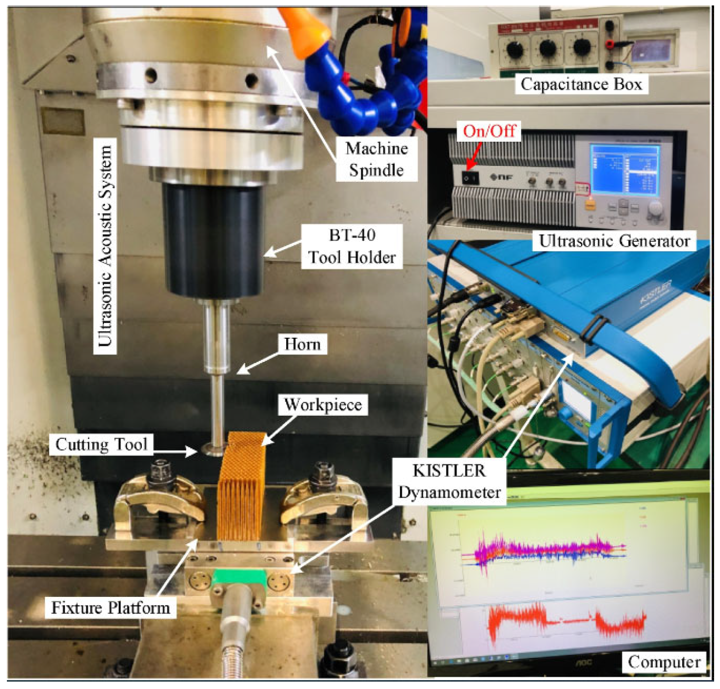
Figure 1. Test bench for ultrasonic-assisted milling of Nomex honeycomb structures.
Eng 07 00177 g001
Figure 2. Geometric description of the honeycomb sample and the elementary cell.
Eng 07 00177 g002
Figure 3. Experimental milling tools: morphological description of (a) UCSB cutter and (b) UCK cutter.
Eng 07 00177 g003
Figure 4. Morphological description and geometric parameters of UCSB and UCK milling cutters.
Eng 07 00177 g004
Figure 5. Simulation configuration under Abaqus: (a) Milling tool engagement and cutting configuration on alveolar structure; (b) Simulation configuration under Abaqus: tool kinematics and meshing of the alveolar material.
Eng 07 00177 g005
Figure 6. Representation of the kinematics of a tool subjected to coupled ultrasonic vibration (longitudinal and torsional).
Eng 07 00177 g006
Figure 7. Parametric analysis of the friction coefficient on the mechanical response in milling.
Eng 07 00177 g007
Figure 8. Effect of cutting width on Fx and Fy in ultrasonic-assisted milling.
Eng 07 00177 g008
Figure 9. Effect of longitudinal and longitudinal-torsional vibrations on adhesive wear.
Eng 07 00177 g009
Figure 10. Influence of tool profile on fragmentation in longitudinal-torsional ultrasonic milling.
Eng 07 00177 g010
Figure 11. Impact of amplitude on the dynamics of the cutting force components.
Eng 07 00177 g011
Figure 12. Sensitivity of the Fx and Fy components to the ultrasonic excitation frequency.
Eng 07 00177 g012
Figure 13. Impact of vibrational frequency on fragmentation and evacuation mechanisms.
Eng 07 00177 g013
Table 1. Mechanical properties of Nomex paper [39].
Mechanical Properties
Density (g/cm3)1.4
E11 (MPa)9200
E22 (MPa)8300
E33 (MPa)4700
G12 (MPa)2600
G13, G23 (MPa)1700
ν12; ν13; ν230.35
Ultimate strength
Longitudinal tensile strength (MPa): Xt111
Longitudinal compressive strength (MPa): Xc53
Transverse tensile strength (MPa): Yt98
Transverse compressive strength (MPa): Yc47
In-plan shear strength (MPa): S1259
Inter-laminar shear strength (MPa): S2315
Table 2. Degradation of mechanical properties and corresponding variables according to the Tsai-Wu criterion.
Elasticity ModulesDamage IndexDegradation of Mechanical Properties
E11H1 E 11 → (1 − d 1 ) E 11
E22H2 E 22 → (1 − d 2 ) E 22
E33H3 E 33 → (1 − d 3 ) E 33
G23H4 E 23 → (1 − d 4 ) E 23
G12H5 E 12 → (1 − d 5 ) E 12
G13H6 E 13 → (1 − d 6 ) E 13
Disclaimer/Publisher’s Note: The statements, opinions and data contained in all publications are solely those of the individual author(s) and contributor(s) and not of MDPI and/or the editor(s). MDPI and/or the editor(s) disclaim responsibility for any injury to people or property resulting from any ideas, methods, instructions or products referred to in the content.