Article

Investigation of Wear Behavior for Innovative Cutting Tool in Machining AISI 304 Stainless Steel

1
School of Physics and Mechatronic Engineering, Guizhou Minzu University, Guiyang 550025, China
2
Guiyang Xianfeng Machine Tool Co., Ltd., Guiyang 550601, China
3
School of Mechanical Engineering, Guizhou University, Guiyang 550025, China
4
School of Mechanical Engineering, Guizhou Institute of Technology, Guiyang 550003, China
*
Author to whom correspondence should be addressed.
Eng 2025, 6(9), 248; https://doi.org/10.3390/eng6090248
Submission received: 13 August 2025 / Revised: 14 September 2025 / Accepted: 16 September 2025 / Published: 22 September 2025
(This article belongs to the Special Issue Emerging Trends and Technologies in Manufacturing Engineering)

Abstract

AISI 304 stainless steel is widely used in the equipment manufacturing industry due to its excellent corrosion resistance. However, its high toughness and plasticity lead to severe tool wear during machining, significantly shortening the tool’s life. To mitigate tool wear, this study designed and fabricated a novel micro-groove structure on the tool’s rake face, aiming to reduce friction and thermal stress. The performance of the micro-groove tool was evaluated through cutting simulations and durability tests. Results demonstrate that this micro-groove structure effectively reduces cutting forces, suppresses tool wear, and improves chip control and heat dissipation.

1. Introduction

Stainless steel 304 possesses excellent mechanical properties, making it widely used in industrial production and equipment manufacturing. However, its high toughness and plasticity lead to significant tool–chip friction during machining, while elevated cutting temperatures accelerate tool wear, thereby increasing processing costs [1,2]. Specifically, 304 stainless steel is prone to work hardening during machining, increasing material hardness and further exacerbating tool wear, severely impacting machining efficiency and the workpiece surface quality [3]. Additionally, its low thermal conductivity hinders effective heat dissipation, causing excessive temperatures in the cutting zone that accelerate tool material softening and wear [4]. Therefore, effectively suppressing tool wear, extending tool life, and reducing machining costs have become critical challenges in the field of 304 stainless steel machining.
To mitigate tool wear, many researchers have developed microstructures such as micro-pits, micro-grooves, regular lattices, and micro-ribbons on the rake face and flank face of tools based on biomimetic principles [5,6,7]. Simulation and experimental studies reveal that these structures reduce the tool–chip contact length, improve lubrication conditions, and decrease tool wear. Numerous scholars have observed that the anti-friction performance of tool surface textures is significantly influenced by their geometric parameters [8,9], such as texture density [10], depth [11], and width [12]. Xu et al. [13] fabricated three distinct microtextures—pits, grooves, and V-shapes—on the rake face of reamers. Cutting experiments demonstrated that microtextured tools significantly reduced cutting forces and improved the workpiece surface quality. Surface texture enhances lubrication conditions, reduces tool wear, and elevates workpiece quality during machining [14]. Arulkirubakaran et al. [15] investigated the effects of parallel, perpendicular, and cross textures on the tool cutting performance, finding that tools with perpendicular textures exhibited optimal cutting performance and superior chip curling effects. Musavi et al. [16] enhanced tool performance by creating microtextured grooves on tungsten carbide tool surfaces. Experimental results demonstrated that microtextured tools improved workpiece surface quality and reduced tool wear under both minimum quantity lubrication (MQL) and dry cutting conditions. Numerous researchers have discovered that cooling techniques can significantly mitigate tool wear. Ahmed et al. [17] proposed a workpiece cooling process based on a refrigeration cycle and compared it with dry machining. Experimental results demonstrated that this cooling method substantially reduced cutting temperatures (by up to 60%), improved surface roughness (by 9%), and decreased tool wear. França et al. [18] proposed an internal tool cooling (ICT) method. Results indicated that both ICT and ICT + MQL methods significantly extended the tool’s life. The primary wear mechanism was abrasive wear, and coating adhesion proved critical to tool durability.
In recent years, scholars have further explored the synergistic effects of tool microgeometry and cooling strategies to mitigate wear in large cutting tools [19,20]. Deng et al. [21] prepared groove textures on the tool rake face and filled the textures with solid tungsten disulfide lubricant. Through cutting experiments, they found that the friction coefficient between the tool and chip was significantly reduced for microtextured tools. Das et al. [22] proposed a lubrication channel design for turning inserts to reduce tool–chip contact forces. Experimental results demonstrated reductions in both friction and cutting forces, along with significant decreases in rake face wear and average surface roughness. Hu et al. [23] investigated the wear performance of five microtextured tool geometries during GH4169 alloy turning under spray cooling conditions through a combined simulation and experimental approach. Shi et al. [24] addressed high cutting temperatures and rapid tool wear in nickel-based, high-temperature alloy machining by preparing three microtexture morphologies on the rake face of cemented carbide tools. Combined with mixed nanofluid minimal quantity lubrication (MQL) technology, cutting experiments were conducted. Results indicate that under nanofluid MQL conditions, microtextures effectively reduce tool–chip friction and enhance heat dissipation, significantly lowering cutting forces and temperatures while extending the tool life.
Concurrently, Pascal [25] and Guo [26] demonstrated that tool coating technologies can also improve the tool wear performance. Other researchers applied animal and plant anti-friction shapes [27,28] to the tool design, substantially reducing the friction coefficient between tools and chips under specific conditions [29,30] and significantly mitigating tool wear.
Tool oxidation wear cannot be observed at the macroscopic level. Therefore, researchers have utilized a wire-cut analysis to examine tool wear zones and employed wire scanning to observe internal element distribution at the tool tip, thereby assessing the extent of oxidation wear [31,32]. Chip morphology can, to some extent, reflect changes in the cutting temperature and cutting force during the machining process [33,34]. Both the cutting force and serrated chip formation initially increase then decrease with a rising cutting speed [35], particularly during adiabatic shear zone formation. Microstructural evolution within the adiabatic shear zone exhibits significant variations across different cutting speeds and chip morphologies, ultimately altering the cutting force due to changes in chip segmentation and fracture mechanisms [36].
This study addresses severe tool wear during AISI 304 stainless steel machining by designing and fabricating a novel micro-groove structure on the rake face. This micro-groove structure aims to effectively reduce tool wear by optimizing the tribological conditions at the tool–chip interface, thereby lowering friction and thermal stress. This approach significantly extends the tool’s life, enhances production efficiency, and reduces overall production costs. The primary objective of this paper is to investigate tool wear during durability testing between the micro-groove tool and the original tool.

2. Experimental Materials and Methods

2.1. Cutting Tool Materials and Parameters

Cutting tools made of cemented carbide are typically used for machining 304 stainless steel. The tool employed in this study, referred to as tool A, features a rhombic-shaped cutting edge provided by a domestic manufacturer. Cutting simulations confirmed that tool B incorporates a micro-groove design at its cutting edge. The tool body is made of M30, primarily composed of WC, with a surface coating of TiAlN (high aluminum content at 67%) and a thickness of 5 μm. The smooth coating surface exhibits a low coefficient of friction, enabling efficient chip evacuation, excellent wear resistance, and superior toughness under medium-to-high-speed machining conditions. As shown in Table 1, tool A and tool B share identical geometric angles.

2.2. DEFORM Model Construction

This paper employs the professional cutting simulation software DEFORM v 11.0 to simulate the machining of AISI 304 stainless steel using tool A. DEFORM features a relatively comprehensive and well-structured material library; during the cutting simulation, the software’s built-in austenitic stainless steel material was utilized. The flow stresses of the material are described in relation to temperature, strain, and strain rate.
The friction conditions in the tool–chip contact zone during cutting are highly complex. Based on the distribution of normal stress and shear stress, the contact surface between the tool and chip is divided into two regions: the adhesion zone and the sliding zone. During the cutting of austenitic stainless steel, the contact stress near the tool tip reaches up to 3 GPa, representing a typical adhesion zone. As the chip approaches the front face, the contact stress decreases, transitioning into the sliding zone. Therefore, this chapter employs a hybrid friction model for tool–chip interaction.
During the numerical simulations in this study, the following assumptions were made based on computational characteristics: (a) The workpiece remains stationary while the tool rotates around the workpiece’s axial center during cutting; (b) the friction coefficient between the tool and chip is set to a fixed value of 0.4; (c) uniform heat exchange occurs between the tool and the external environment; and (d) the heat transfer coefficient between the tool and chip is set to 2000 kW/(m2·K), while the convective heat transfer coefficient between the cutting system and the environment is 20 kW/(m2·K). Both tool and workpiece initial temperatures are set to 20 °C. The tool employs adaptive mesh refinement. The workpiece is modeled as a plastic body using the AISI 304 material (TISCO in Taiyuan City, Shanxi Province, China), also utilizing adaptive mesh refinement.

2.3. Cutting Force and Wear Measurement

To comprehensively evaluate the cutting performance of tools, this study designed cutting endurance tests for the original tool A and the micro-grooved tool B. The cutting tests were conducted on a C2-6136HK CNC lathe, utilizing a Kistler-9257B force transducer to measure three-axis cutting forces for process validation. All tests were conducted under dry cutting conditions. Cutting parameters matched those used in the cutting simulation. Both tools A and B operated at 2 min cutting intervals, with cutting forces and tool wear recorded during each interval. The design of the endurance cutting test is shown in Table 2.
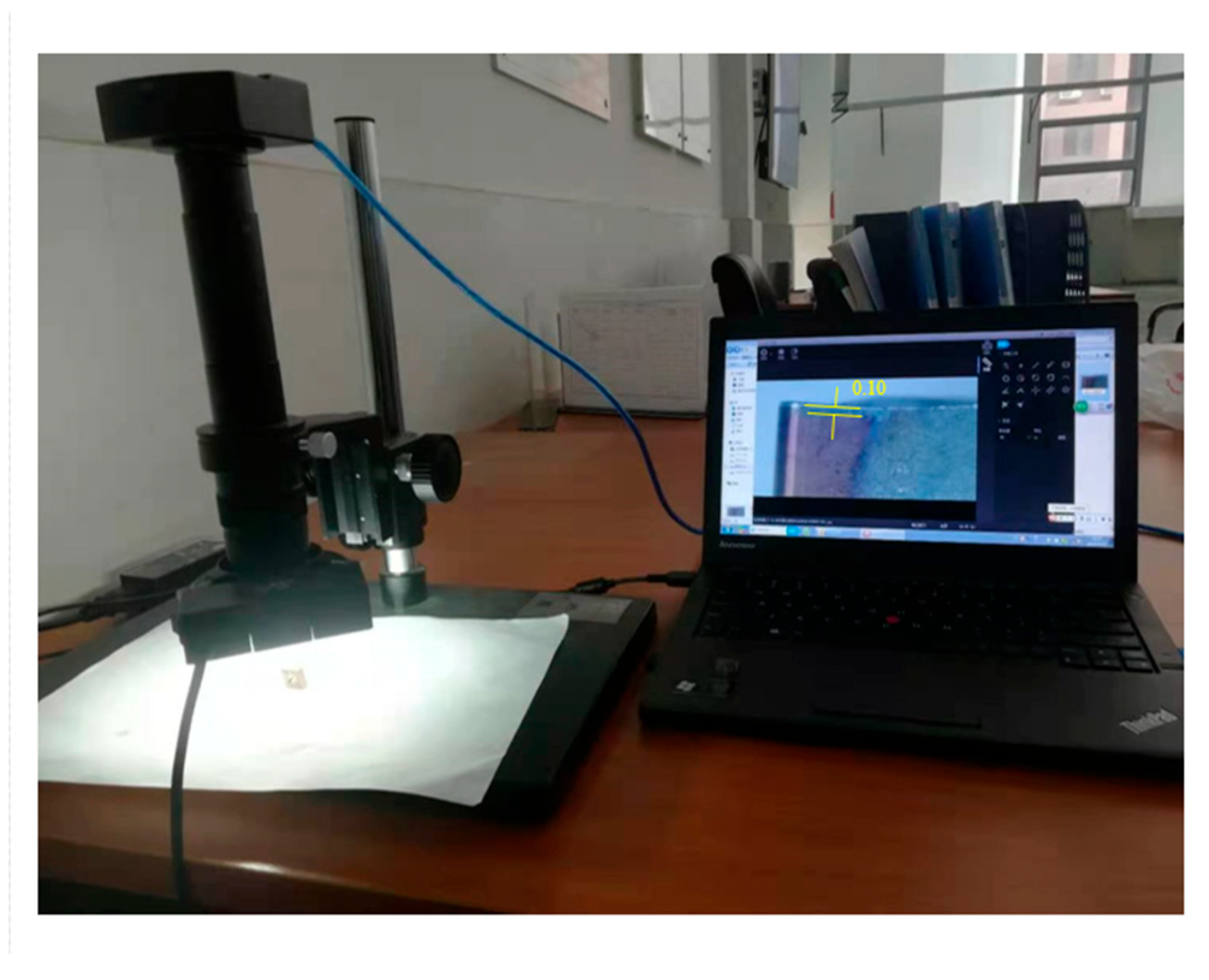
Figure 1 displays tool A, tool B, and the associated cutting and testing equipment. Based on prior research, tool failure is determined when the cutting edge wear width reaches 0.15 mm during stainless steel machining [37,38]. The wear width of the rake face was measured using a super depth of field microscope, with the wear measurement equipment shown in Figure 2 below.
This study employs a combined approach of simulation modeling and experimental design to conduct wear resistance tests on the designed cutting tool. It analyzes the tool’s triaxial cutting forces, tool wear, tool element energy spectrum, and chip morphology under macro-level observation. Compared to the original tool, the micro-groove tool designed in this paper demonstrates significantly enhanced performance. The overall research process and plan for this paper are shown in Figure 3.

3. Tool Cutting Experiments and Wear Research

3.1. Simulation Results

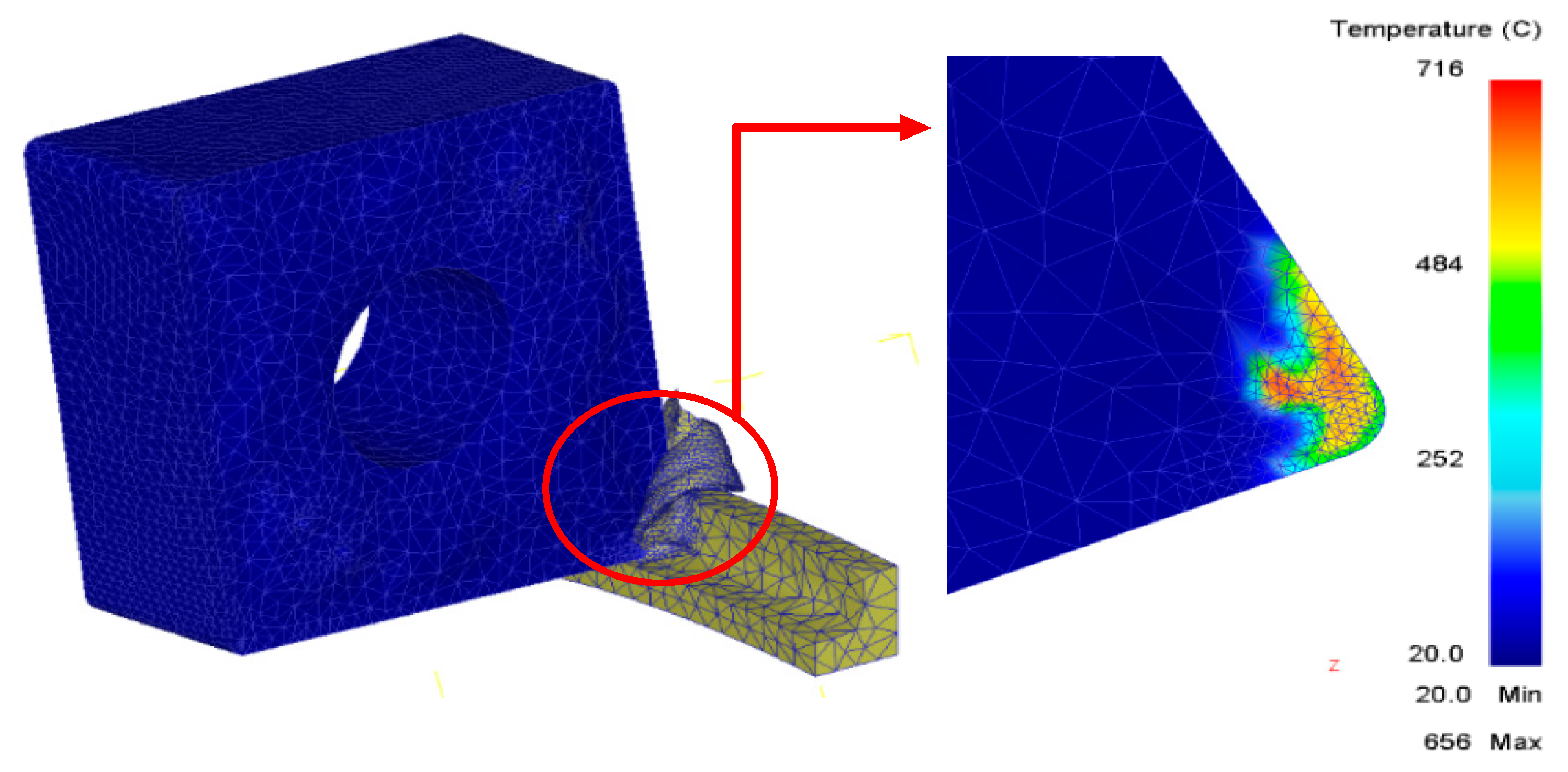
First, using the specialized cutting simulation software DEFORM [39,40], the cutting simulation was performed on AISI 304 stainless steel using tool A. Based on the cutting parameter range recommended by the manufacturer and after trial cutting tests, the following cutting parameters were adopted: cutting speed V = 120 m/min, feed rate f = 0.15 mm, and cutting depth ap = 1.5 mm. The temperature distribution on the front face of the tool is shown in Figure 4.
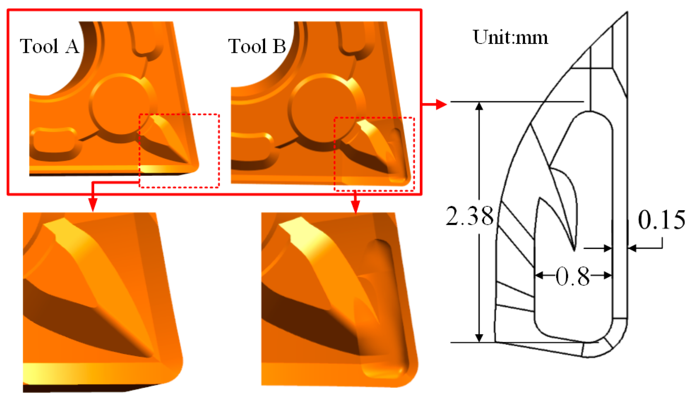
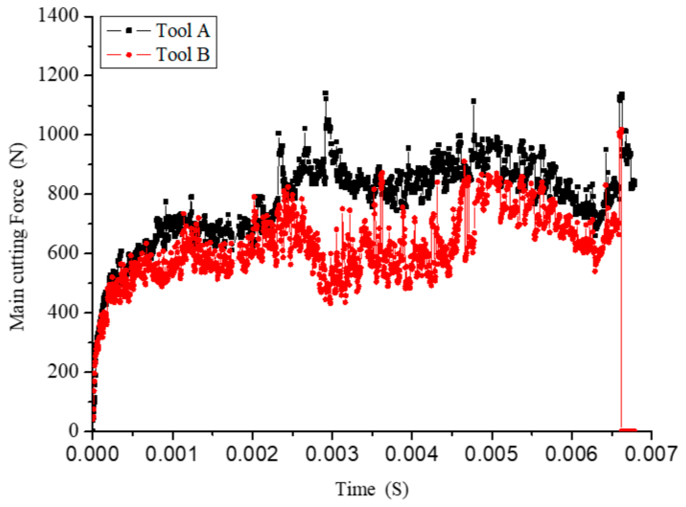
In the vicinity of the primary and secondary cutting edges on the front face of the tool, high temperatures are concentrated [41]. This region is where intense friction occurs between the tool and workpiece, as well as between the tool and chips. The paper uses this region as the basis for micro-groove design, determining the three-dimensional dimensions of the micro-grooves based on the temperature field distribution data and designing an innovative tool accordingly [42]. The micro-groove size of tool B is shown in Figure 5; the depth of the micro-groove is 1.5 mm. The tool is manufactured by powder metallurgy. It was found that the newly designed micro-groove tool exhibited a significant reduction in the cutting force, as shown in Figure 6. Therefore, tool B, with micro-grooves, was manufactured using the same powder metallurgy method. Both tools A and B are made of a tungsten carbide-based hard alloy, with a TiAlN coating on their surfaces.

3.2. Comparison of Cutting Forces

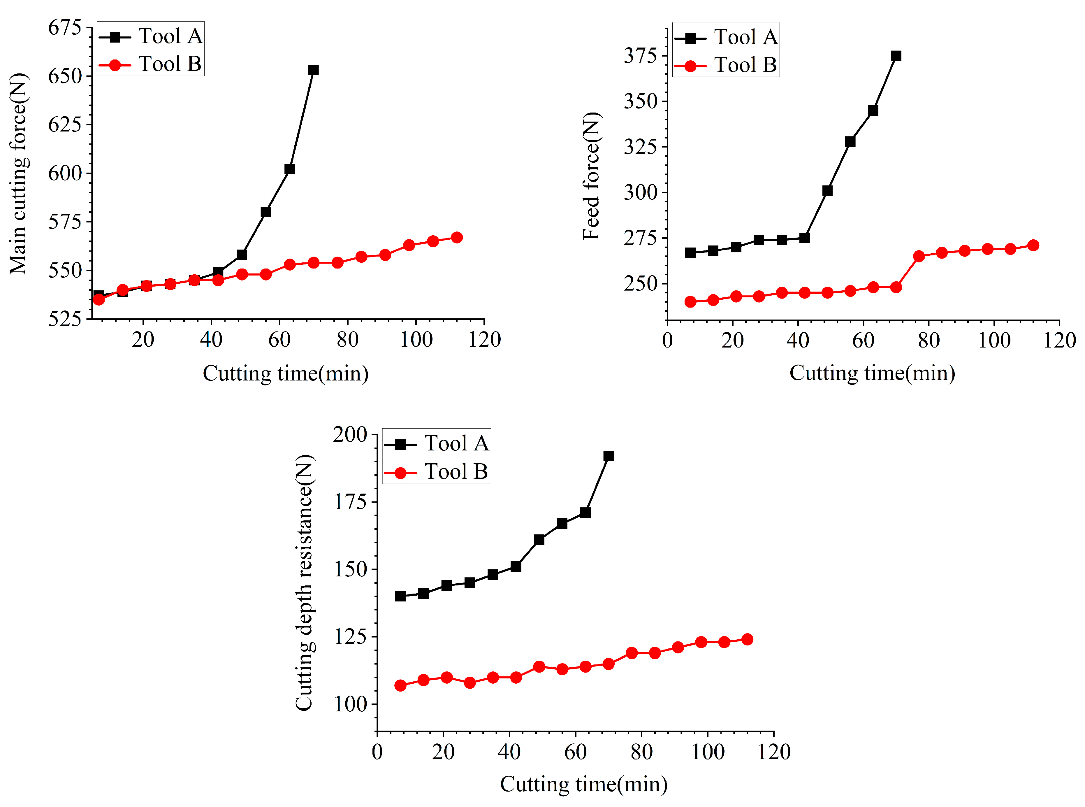
During the cutting durability experiment, the cutting forces of tools A and B were measured using a force gauge. Through cutting experiments, it was found that throughout the entire cutting process, as shown in Figure 7, the cutting forces of tool B decreased to varying degrees. The maximum reduction in the main cutting force exceeded 20%, the minimum reduction in the depth of cut resistance was over 5%, and the minimum reduction in the feed resistance exceeded 5%. As shown in Figure 5, compared to the original tool A, the three-directional cutting forces of tool B all decreased to some extent. From the figure, it can be seen that the time from the start of cutting to failure for tool B was 110 min, while for tool A it was 67 min, indicating that the cutting time for tool B was extended by over 50%.

3.3. Comparison of Tool Wear Morphology

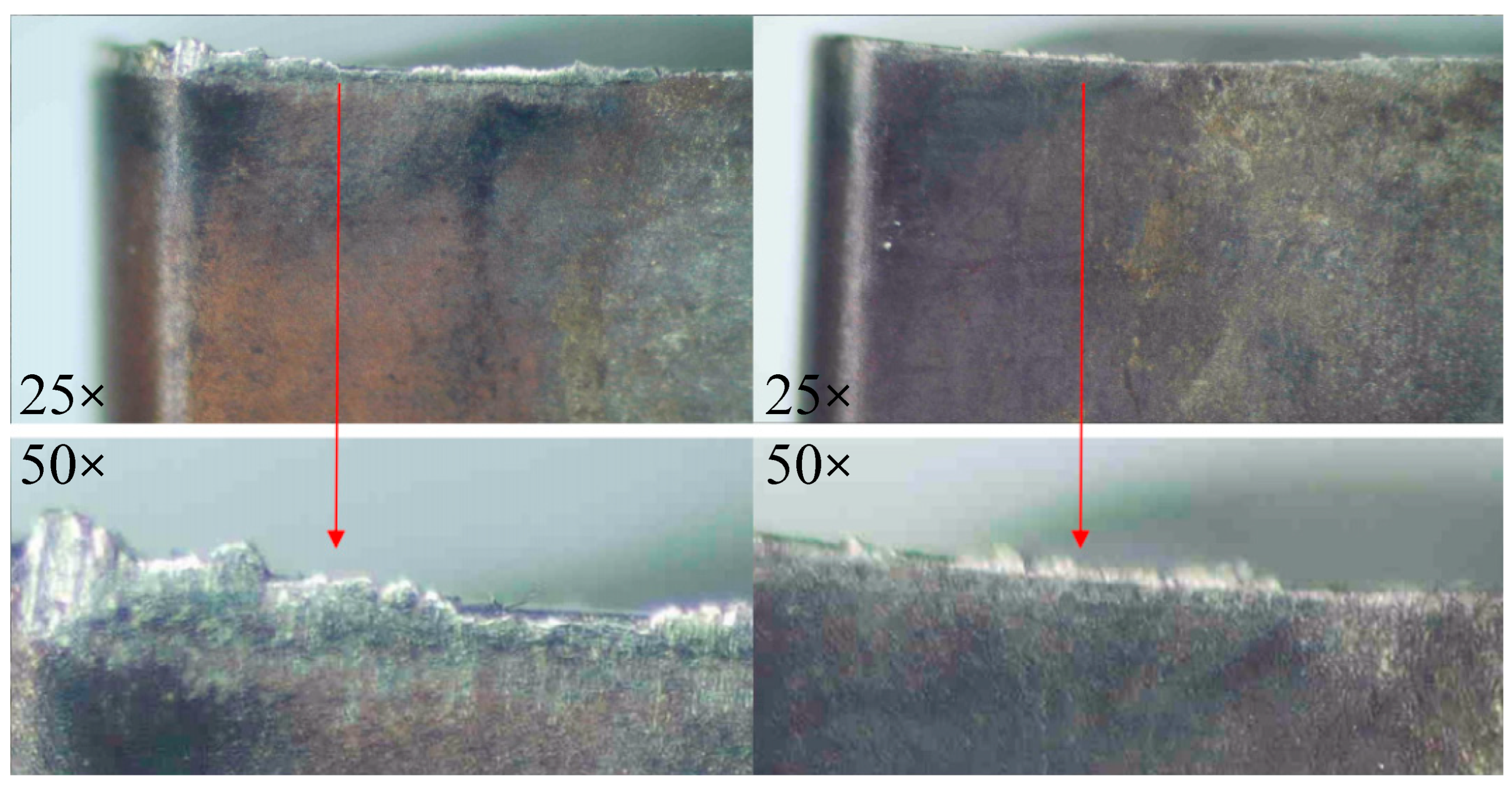
As shown in Figure 8, tool A exhibits severe wear in the vicinity of the cutting edge. Due to the combined effects of the rake angle, main rake angle, and edge inclination angle, the cutting edge contact stress is highest at a distance of approximately 1.5 mm from the tool tip. The main cutting edge shows significant wear, particularly at the point where the chip enters the front face inlet, where the cutting edge has already fractured [38].
As can be seen from Figure 8, the front face of tool B also experienced wear, but the cutting edge showed almost no significant deformation. Significant wear occurred only at the chip-breaking position of the tool, and slight chipping occurred at the entrance of the front face where the chip entered. The overall integrity of the tool was better maintained.
As can be seen from Figure 9, the rear cutting edge of tool A exhibits significant wear at the lower position, with the maximum wear width occurring 1.5 mm from the tool tip, which aligns with the location of chipping on the front cutting edge [37]. By measuring the wear width at this point, it is found to exceed 0.15 mm. Tool B has a smaller average wear width, with the maximum wear width at the cutting edge being 0.15 mm. Additionally, the area of the chipped region on the rear cutting edge of tool B is smaller compared to that of tool A.

3.4. SEM Scanning and Line Scan Comparison of the Rake and Flank Faces of the Tools

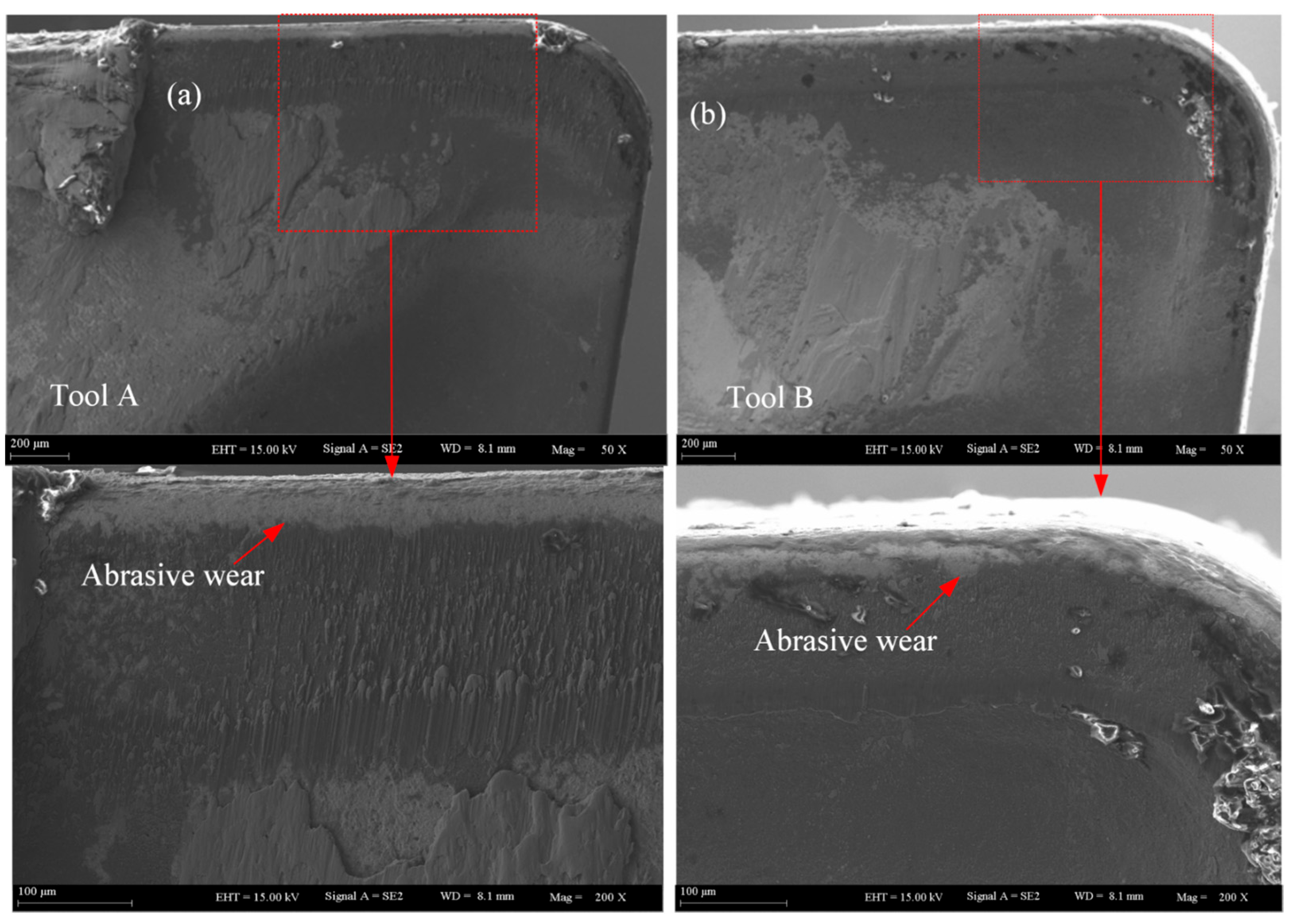
Using SEM, scanning electron microscopy, to scan the front cutting edges of tools A and B, it can be seen from Figure 10 that tool A has obvious abrasive grain lines, with very large adhesive blocks at the left end of the cutting edge and severe material spalling at the main cutting edge. As can be seen from Figure 10, when the area near the cutting edges of tools A and B is magnified, it is observed that the rake face of tool A has a relatively severe abrasive line. At the position where the cutting edge turns white, it is the severely worn area of the tool’s abrasive material, revealing the base material of the tool. When comparing tool A and tool B, the area where the cutting edge turns white is significantly larger for tool A than for tool B. This indicates that after the cutting durability test, tool A suffered more severe abrasive wear and adhesive wear.
Similarly, SEM, scanning electron microscopy, was used to perform an energy-dispersive spectroscopy analysis on the front face of the cutting tools. As shown in Figure 11, tool A exhibits a higher concentration of iron elements in the severely worn areas, while tool B has an iron concentration in the same areas that is approximately one-quarter that of tool A [37]. The concentration of oxygen elements is similar between tool A and tool B in the uppermost region, but when the distance exceeds 200 μm, the oxygen concentration of tool A rapidly increases to nearly four times that of tool B. According to cutting principles, the tool itself does not carry iron elements; these iron elements are the main material of the workpiece. Therefore, the iron elements on the tool surface are all workpiece surface elements that have adhered to the workpiece surface through compression and friction. The average iron element concentration on the front face of tool A is significantly higher than that of tool B, indicating that tool A has more severe adhesive wear. Oxygen is present in the air. During the cutting process, due to high temperatures, the iron elements on the tool surface react with oxygen in the air to form oxidation. Since tool B has a lower average oxygen depth, it indicates that tool B has lower oxidation wear.
Through scanning the flank face of the cutting tool with SEM, it was found in Figure 12 that tool A had very obvious adhesion blocks, with severe material abrasion on the cut-ting edge toward the flank face. Tool B had almost no adhesion, with only slight material abrasion.
Through line scanning at the same position, the iron element concentration distribution of tool A is dense, and the average concentration is much higher than that of tool B. The iron element comes from the workpiece, indicating that tool A has more severe abrasive wear and adhesive wear.
The average O concentration in this area of tool A is higher than that of tool B, indicating that the surface temperature of tool A is higher during the cutting process, making it more prone to oxidation reactions.
During the machining of 304 stainless steel, the temperature in the tool–chip contact zone can exceed 700 °C. In areas of close contact between the tool and chip, the workpiece material and tool material become tightly interlocked, facilitating the mutual dissolution and diffusion of chemical elements between the two contacting materials. This process accelerates the material composition and structural changes, thereby intensifying the tool wear. This paper will examine the wear zones of cutting tools A and B through wire cutting and observe the distribution of Fe and O elements via line scanning. After cutting, tools A and B are shown in Figure 13.
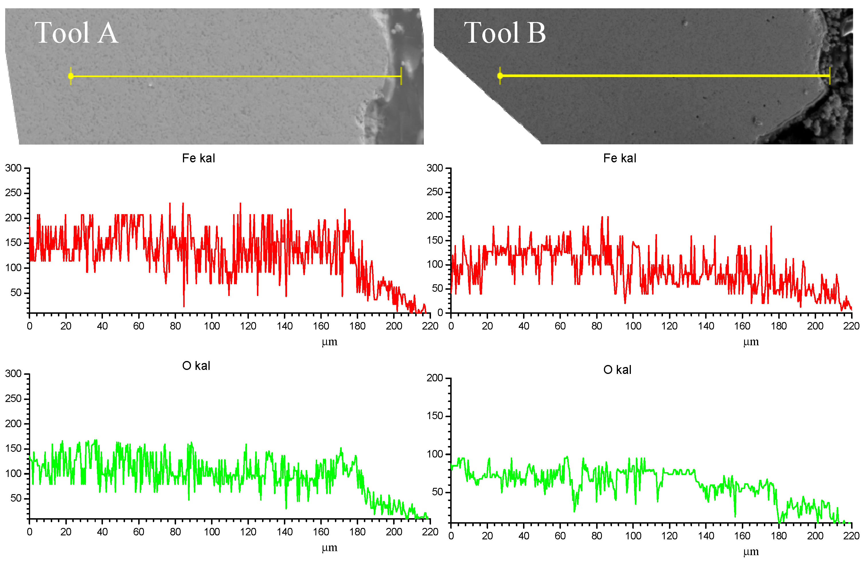
As can be seen from Figure 14, an EDS analysis of the tool interior after wire cutting revealed that the average Fe content of tool A was close to 200, while that of tool B was close to 150. Tool A’s Fe content was significantly higher than that of tool B. This indicates that during the cutting process, the wear area of tool A had closer contact with the chips compared to tool B, resulting in more Fe elements from the workpiece penetrating into the tool interior and causing more severe diffusion wear.
Similarly, the average O element content of tool A was approximately 150, while that of tool B was approximately 80. This indicates that the surface temperature of tool A was higher during the cutting process, providing better conditions for oxidation reactions, resulting in higher O element content within the tool and more severe oxidation wear.
During the cutting process, tool A exhibits a significantly higher diffusion wear than tool B, further indicating that the contact stress between the tool and the chip is greater, and the temperature is higher during the cutting process.

3.5. Macroscopic Morphology Comparison of Tool Cutting Chips

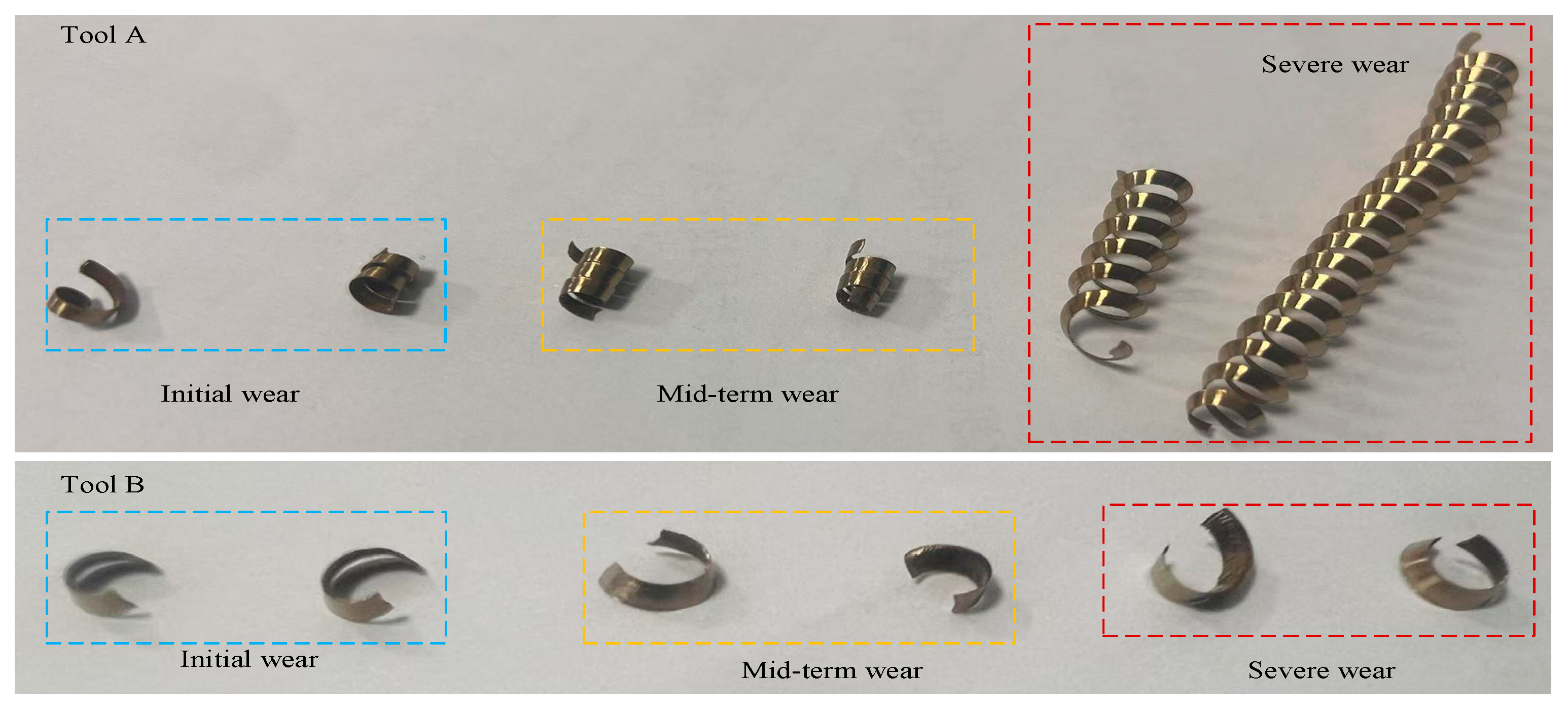
During metal cutting processes, the intense interaction between cutting tools and workpieces induces plastic slip along shear planes, accompanied by lattice distortion and a surge in dislocation density [43]. The deformed material undergoes complex multiaxial stresses at the tool’s rake face, ultimately forming chips with specific morphological characteristics. A comparative analysis of chip macrostructures—such as oxidation color gradients reflecting temperature gradients and curling patterns indicating flow stability—between micro-grooved tools and conventional tools holds significant importance. This analysis essentially visualizes the thermal–mechanical load distribution and energy transfer efficiency within the cutting zone. Due to the relative motion between the tool and the workpiece, the chips eventually flow out from the front face of the tool. Changes in chip morphology reflect the deformation behavior of the workpiece shear zone and the tool–chip contact zone. As shown in Figure 15, as the cutting time increases, chip breakage becomes increasingly difficult for tool A. When the tool reaches the dullness standard, the chip curl height is 60 mm. Tool B consistently produces C-type chips with good chip breakage. This indicates that, during the cutting process, tool A experiences higher cutting temperatures, leading to a reduced chip-breaking capability, while tool B operates at lower temperatures, resulting in smoother cutting and a normal chip morphology.

4. Results and Discussion

During the cutting process, the friction at the chip-to-tool interface primarily consists of two components: first, the inner friction zone near the tool tip, where high temperatures and pressures cause severe plastic deformation of the chip’s underlying material, leading to adhesion with the tool’s rake face material, also known as the adhesion friction zone. Second, the outer friction zone, which is distant from the tool tip. This region experiences lower pressures and temperatures, adhering to Coulomb’s friction law, and is referred to as the sliding friction zone.
As shown in Figure 7, the cutting force exhibits a highly consistent correlation with changes in chip morphology at line 193. Tool A’s primary cutting force surged sharply with the cutting time, indicating severe tool wear that dulled the cutting edge, increased the contact area with the workpiece, and intensified friction. This abrupt increase in the cutting force subjected the material to more intense plastic deformation, resulting in significantly more irregularly shaped chips. As temperatures rose, tool A’s chip-breaking capability diminished. Conversely, tool B’s primary cutting force increased only gradually, indicating superior wear resistance. It maintained a sharp cutting edge and stable cutting conditions for a longer duration. Consequently, the chips produced remained relatively stable and uniform in both quantity and morphology throughout the entire process.
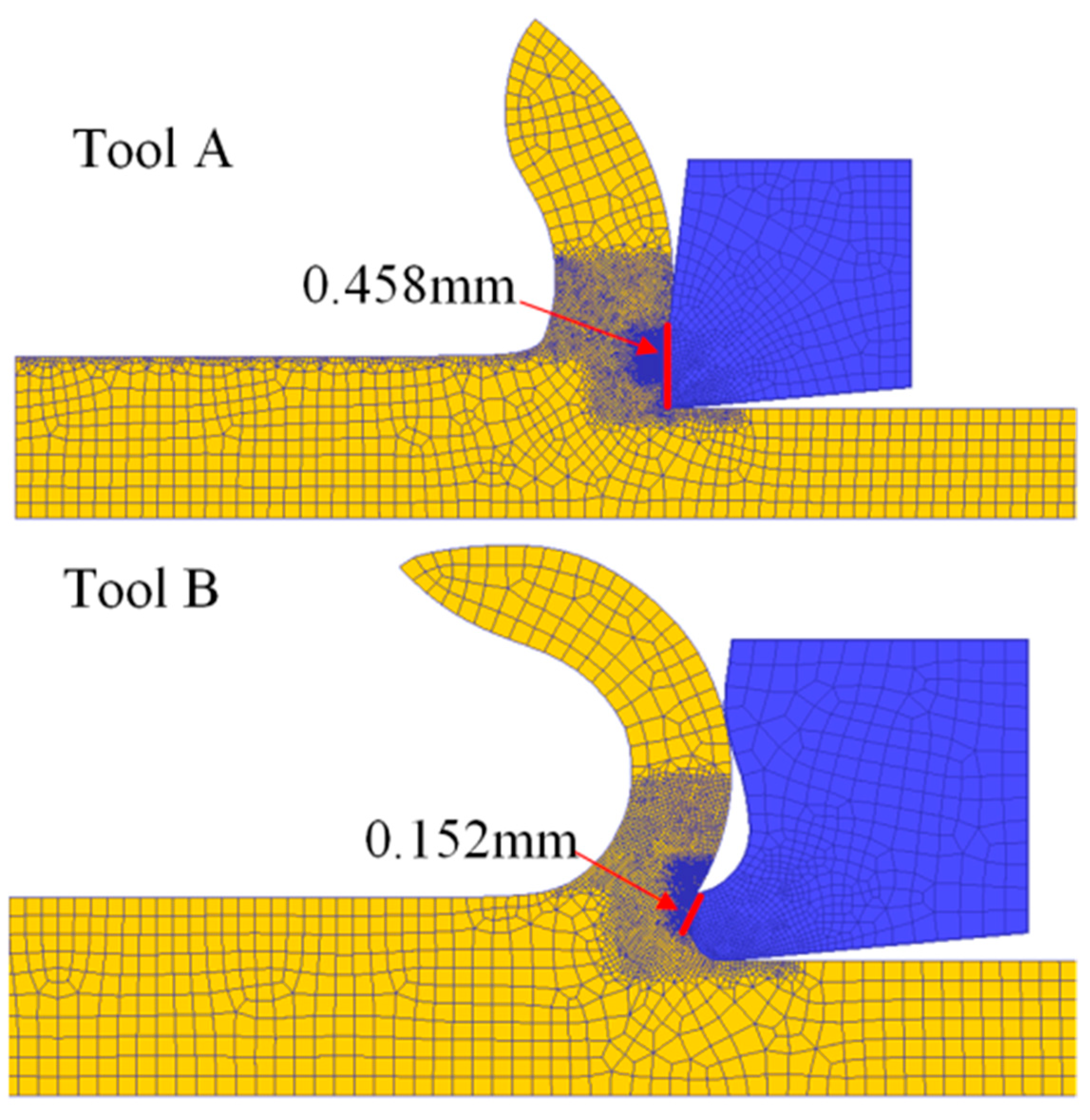
The introduction of micro-grooves in tool B alters the contact between the chip and the tool, reducing the actual contact length between the tool and the chip. The length of the high-stress adhesive friction zone is approximately one-third that of the original tool A, as shown in Figure 16 below [38]. Additionally, due to the width of the micro-grooves, the width of the sliding friction zone in tool B is approximately half that of tool A. Therefore, during the cutting process, the friction state between the tool and the chip is improved, cutting heat is reduced, cutting temperature decreases, cutting force is reduced, and the adhesive wear and oxidation wear of the tool are alleviated. Additionally, the micro-grooves increase the tool’s rake angle, making the tool sharper, improving the plowing performance, reducing the degree of plastic deformation in the chip, and decreasing the input of cutting energy.
Due to the micro-groove on the front face of tool B, chips will penetrate deeper into the micro-groove during cutting. According to force analysis, the front angle and shear angle of tool B are larger than those of tool A, making the tool sharper and the cutting process smoother.
Fan et al. [44] investigated the effect of microtextures on the cutting performance of polycrystalline cubic boron nitride (PCBN) tools. Under identical cutting conditions, microtextured tools exhibited a smaller chip–tool contact area, lower cutting force, reduced chip radius, and improved surface roughness compared to non-textured tools. Additionally, the greater shear angle mitigated the tool adhesion wear. Meanwhile, Pang et al. [45] and Ge et al. [46] discovered that designing microgrooves on cutting tools enhances their cutting performance. Tools with micro-groove structures exhibit reduced cutting forces, chip friction coefficients, and surface wear, significantly extending the tool’s life.

5. Conclusions

To address the issue of tool wear during the machining of stainless steel 304, this paper proposes the design of micro-groove textures on the tool’s rake face. Cutting experiments were conducted using the original tool A and the micro-grooved tool B, with comparisons made between the cutting forces, tool wear, and chip morphology during the machining process. The experimental phenomena were analyzed, and the following conclusions were drawn:
  • Compared to tool A, the introduction of micro-grooves in tool B resulted in larger rake angles and shear angles during the cutting process, the reduced plastic deformation of the chips, and decreased cutting energy input.
  • Through surface morphology observation, the wear on the front and back faces of tool B was less severe than that of tool A, with shallower wear marks. Additionally, the distribution of primary elements and local energy spectrum analysis indicate that both the adhesive wear and oxidative wear on tool B are less severe than those on tool A.
  • The presence of micro-grooves alters the tool–chip contact state, reducing the length of the tool–chip friction zone. As a result, the energy generated by tool–chip friction decreases, leading to lower cutting temperatures, reduced chip plastic deformation, and improved chip breaking.

Author Contributions

Conceptualization, J.W., W.H. and Y.W.; methodology, J.W. and Y.Z.; validation, J.W., Y.Z. and Y.W.; formal analysis, J.W.; investigation, J.W. and W.H.; resources, J.W., Y.W., Y.Z., C.W. and Z.Y.; data curation, W.H. and Y.Z.; writing—original draft preparation, J.W.; writing—review and editing, Y.W., C.W. and W.H.; visualization, Y.W. and W.H. supervision, Y.W.; project administration, J.W. and Y.W. funding acquisition, J.W. and Y.W. All authors have read and agreed to the published version of the manuscript.

Funding

This study was supported by the Guizhou Minzu University Scientific Research Fund Sponsored Project. (No. GZMUZK [2022]YB01); Doctoral funding project of Guizhou Minzu University GZMUZK [2024]QD72; Guizhou Provincial Science and Technology Program Projects (Grant No: KJZY [2025]082 and No: KJZY [2025]080).

Conflicts of Interest

Authors Jinxing Wu, Wenhao Hu, Yi Zhang, Changcheng Wu and Zuode Yang were employed by the company Guiyang Xianfeng Machine Tool Co., Ltd. The authors declare that the research was conducted in the absence of any commercial or financial relationships that could be construed as a potential conflict of interest.

References

  1. Li, Z.; Jiang, M.; Guo, X.; Zhang, K. Improving the frictional properties of the tool/chip interface of micro-textured ceramics tools by using electromagnetic-assisted nanofluids. Mater. Today Commun. 2024, 39, 109017. [Google Scholar] [CrossRef]
  2. Zou, P.; Zhou, L.; Yang, Z.; Ren, B.; Wang, X. Effect of texture location in tool-chip friction region on cutting performance in turning AISI 304. Int. J. Adv. Manuf. Technol. 2024, 132, 2787–2805. [Google Scholar] [CrossRef]
  3. Kumar, A.; Sharma, R.; Kumar, S.; Verma, P. A review on machining performance of AISI 304 steel. Mater. Today Proc. 2022, 56, 2945–2951. [Google Scholar] [CrossRef]
  4. Junaidh, A.P.; Yuvaraj, G.; Peter, J.; Bhuvaneshwari, V.; Karthik, K. Influence of process parameters on the machining characteristics of austensite stainless steel (AISI 304). Mater. Today Proc. 2018, 5, 13321–13333. [Google Scholar] [CrossRef]
  5. Maharana, H.S.; Kumar, R.; Murty, S.N.; Ramkumar, J.; Mondal, K. Surface micro-texturing of dual phase steel and copper by combining laser machining and electrochemical dissolution. J. Mater. Process. Technol. 2019, 273, 116260. [Google Scholar] [CrossRef]
  6. Jianxin, D.; Wenlong, S.; Hui, Z. Design, fabrication and properties of a self-lubricated tool in dry cutting. Int. J. Mach. Tools Manuf. 2009, 49, 66–72. [Google Scholar] [CrossRef]
  7. Jianxin, D.; Ze, W.; Yunsong, L.; Ting, Q.; Jie, C. Performance of carbide tools with textured rake-face filled with solid lubricants in dry cutting processes. Int. J. Refract. Met. Hard Mater. 2012, 30, 164–172. [Google Scholar] [CrossRef]
  8. Xu, Y.; Zheng, Q.; Abuflaha, R.; Olson, D.; Furlong, O.; You, T.; Tysoe, W.T. Influence of dimple shape on tri-bofilm formation and tribological properties of textured surfaces under full and starved lubrication. Tribol. Int. 2019, 136, 267–275. [Google Scholar] [CrossRef]
  9. Romano, J.M.; Garcia-Giron, A.; Penchev, P.; Dimov, S. Triangular laser-induced submicron textures for function-alising stainless steel surfaces. Appl. Surf. Sci. 2018, 440, 162–169. [Google Scholar] [CrossRef]
  10. Liu, W.; Ni, H.; Chen, H.; Wang, P. Numerical simulation and experimental investigation on tribological perfor-mance of micro-dimples textured surface under hydrodynamic lubrication. Int. J. Mech. Sci. 2019, 163, 105095. [Google Scholar] [CrossRef]
  11. Choi, Y.; Lee, J. A study on the effects of surface dimple geometry on fretting fatigue performance. Int. J. Precis. Eng. Manuf. 2015, 16, 707–713. [Google Scholar] [CrossRef]
  12. Schneider, J.; Braun, D.; Greiner, C. Laser textured surfaces for mixed lubrication: Influence of aspect ratio, textured area and dimple arrangement. Lubricants 2017, 5, 32. [Google Scholar] [CrossRef]
  13. Xu, R.; Yongfeng, Y. Effect of micro-texture of flank surface on broaching force and surface quality of workpiece. Appl. Surf. Sci. 2020, 146558. [Google Scholar] [CrossRef]
  14. Xie, Z.; Li, J.; Tian, Y.; Du, P.; Zhao, B.; Xu, F. Theoretical and experimental study on influences of surface texture on lubrication performance of a novel bearing. Tribol. Int. 2024, 193, 109351. [Google Scholar] [CrossRef]
  15. Arulkirubakaran, D.; Senthilkumar, V.; Kumawat, V. Effect of micro-textured tools on machining of Ti-6Al-4V alloy: An experimental and numerical approach. Int. J. Refract. Met. Hard Mater. 2016, 54, 165–177. [Google Scholar] [CrossRef]
  16. Musavi, S.H.; Sepehrikia, M.; Davoodi, B.; Niknam, S.A. Performance analysis of developed micro-textured cut-ting tool in machining aluminum alloy 7075-T6: Assessment of tool wear and surface roughness. Int. J. Adv. Manuf. Technol. 2022, 119, 3343–3362. [Google Scholar] [CrossRef]
  17. Ahmed, S.; Sagor, S.I.; Akbar, N.I.; Mahmud, M.M.; Mostofa, M.G. The influence of a newly developed refrigeration cycle based workpiece cooling method in milling AISI 304 stainless steel. Results Eng. 2023, 20, 101616. [Google Scholar] [CrossRef]
  18. França, P.H.; Barbosa, L.M.; Fernandes, G.H.; Machado, Á.R.; Martins, P.S.; da Silva, M.B. Internally cooled tools: An eco-friendly approach to wear reduction in AISI 304 stainless steel machining. Wear 2024, 554, 205490. [Google Scholar] [CrossRef]
  19. Roy, N.A.P.; Rao, K.J.; Amrita, M. Influence of tool micro-texturing, cooling conditions and cutting conditions on workpiece surface integrity and tool condition. J. Micromanuf. 2025, 25165984241308627. [Google Scholar] [CrossRef]
  20. Elajrami, Z.; Shi, G. Microtextured tools with cooling technology: A concise review. Int. J. Adv. Manuf. Technol. 2024, 135, 5071–5084. [Google Scholar] [CrossRef]
  21. Deng, J.; Lian, Y.; Wu, Z.; Xing, Y. Performance of femtosecond laser-textured cutting tools deposited with WS2 solid lubricant coatings. Surf. Coat. Technol. 2013, 222, 135–143. [Google Scholar] [CrossRef]
  22. Das, A.; Bajpai, V. Turning insert with lubricating passage along the normal plane for minimization of friction, cutting force and tool wear. J. Manuf. Process. 2023, 101, 141–155. [Google Scholar] [CrossRef]
  23. Hu, J.; Wei, J.; Feng, X.; Liu, Z. Research on Wear of Micro-Textured Tools in Turning GH4169 during Spray Cooling. Lubricants 2023, 11, 439. [Google Scholar] [CrossRef]
  24. Shi, Y.; Zheng, J.; Peng, C.; Guo, L.; Shi, W.; Feng, P.; Zhao, R. An investigation into the impact of tool surface texture on the cutting property of nickel-based superalloys under MQL conditions. Int. J. Adv. Manuf. Technol. 2025, 139, 6157–6172. [Google Scholar] [CrossRef]
  25. Pascal, V.; Jannis, S.; Zabel, A.; Dirk, B. Influence of cutting tool coating on rake and flank face temperatures by operando pyrometric temperature measurement during orthogonal turning of AISI 316L. Wear 2025, 571, 205848. [Google Scholar]
  26. Guo, L.; Liang, Z.Q.; Du, Y.C.; Sun, Y.H.; Shi, J.L.; Zhang, R.; Su, Z.P. Study on the cutting performance of AlTiN/AlTiSiN composite coating tool in deep-hole pull boring tool of GH4169. Tribol. Int. 2025, 202, 110236. [Google Scholar] [CrossRef]
  27. Chen, H.; Zhang, P.; Zhang, L.; Liu, H.; Jiang, Y.; Zhang, D.; Jiang, L. Continuous directional water transport on the peristome surface of Nepenthes alata. Nature 2016, 532, 85–89. [Google Scholar] [CrossRef] [PubMed]
  28. Liu, Y.; Li, G. A new method for producing “Lotus Effect” on a biomimetic shark skin. J. Colloid Interface Sci. 2012, 388, 235–242. [Google Scholar] [CrossRef] [PubMed]
  29. Zhao, Y.; Su, Y.; Hou, X.; Hong, M. Directional sliding of water: Biomimetic snake scale surfaces. Opto-Electron. Adv. 2021, 4, 210008-1. [Google Scholar] [CrossRef]
  30. Xu, L.; Yang, L.; Yang, S.; Xu, Z.; Lin, G.; Shi, J.; Guo, Y. Earthworm-inspired ultradurable superhydrophobic fab-rics from adaptive wrinkled skin. ACS Appl. Mater. Interfaces 2021, 13, 6758–6766. [Google Scholar] [CrossRef]
  31. Heinrichs, J.; Mikado, H.; Kawakami, A.; Wiklund, U.; Kawamura, S.; Jacobson, S. Wear mechanisms of WC-Co cemented carbide tools and PVD coated tools used for shearing Cu-alloy wire in zipper production. Wear 2019, 420, 96–107. [Google Scholar]
  32. Grigoriev, S.N.; Volosova, M.A.; Okunkova, A.A.; Fedorov, S.V.; Hamdy, K.; Podrabinnik, P.A.; Porvatov, A.N. Wire tool electrode behavior and wear under discharge pulses. Technologies 2020, 8, 49. [Google Scholar] [CrossRef]
  33. Xi, Y.; Bermingham, M.; Wang, G.; Dargusch, M. SPH/FE modeling of cutting force and chip formation during thermally assisted machining of Ti6Al4V alloy. Comput. Mater. Sci. 2014, 84, 188–197. [Google Scholar] [CrossRef]
  34. Wu, Q.; Zhang, L. Microstructure-based three-dimensional characterization of chip formation and surface genera-tion in the machining of particulate-reinforced metal matrix composites. Int. J. Extrem. Manuf. 2020, 2, 045103. [Google Scholar]
  35. Liu, G.; Shah, S.; Özel, T. Material ductile failure-based finite element simulations of chip serration in orthogonal cutting of titanium alloy Ti-6Al-4V. J. Manuf. Sci. Eng. 2019, 141, 041017. [Google Scholar] [CrossRef]
  36. Liu, H.; Zhang, J.; Xu, X.; Zhao, W. Experimental study on fracture mechanism transformation in chip segmenta-tion of Ti-6Al-4V alloys during high-speed machining. J. Mater. Process. Technol. 2018, 257, 132–140. [Google Scholar] [CrossRef]
  37. Wu, J.; Zhan, G.; He, L.; Zou, Z.; Zhou, T.; Du, F. Tribological performance of micro-groove tools of improving tool wear resistance in turning AISI 304 process. Materials 2020, 13, 1236. [Google Scholar] [CrossRef]
  38. Zou, Z.; He, L.; Jiang, H.; Zhan, G.; Wu, J. Development and analysis of a low-wear micro-groove tool for turning Inconel 718. Wear 2019, 420, 163–175. [Google Scholar] [CrossRef]
  39. Chen, G.; Caudill, J.; Ren, C.; Jawahir, I.S. Numerical modeling of Ti-6Al-4V alloy orthogonal cutting considering microstructure dependent work hardening and energy density-based failure behaviors. J. Manuf. Process. 2022, 82, 750–764. [Google Scholar] [CrossRef]
  40. Gupta, M.K.; Korkmaz, M.E.; Sarıkaya, M.; Krolczyk, G.M.; Günay, M.; Wojciechowski, S. Cutting forces and temperature measurements in cryogenic assisted turning of AA2024-T351 alloy: An experimentally validated simulation approach. Measurement 2022, 188, 110594. [Google Scholar] [CrossRef]
  41. Wu, J.; He, L.; Wu, Y.; Zhou, C.; Zou, Z.; Zhan, G.; Zhang, X. Enhancing wear resistance and cutting performance of a long-life micro-groove tool in turning AISI 201. Coatings 2021, 11, 1515. [Google Scholar] [CrossRef]
  42. Liu, Z.H.; Wu, J.X. Study on Cutting Performance of Micro Groove Tool in Turning AISI 304 and Surface Quality of the Workpiece. Coatings 2022, 12, 1326. [Google Scholar] [CrossRef]
  43. Şirin, Ş. Investigation of the performance of cermet tools in the turning of Haynes 25 superalloy under gaseous N2 and hybrid nanofluid cutting environments. J. Manuf. Process. 2022, 76, 428–443. [Google Scholar] [CrossRef]
  44. Fan, L.; Deng, Z.; Gao, X.; He, Y. Cutting performance of micro-textured PCBN tool. Nanotechnol. Precis. Eng. 2021, 4, 023004. [Google Scholar] [CrossRef]
  45. Pang, M.; Yang, H.; Li, Y.; Wang, Z.; Ma, L.; Su, J.; Hayat, M. Effect of micro-grooved texture on cutting performance of tool under dry condition. Int. J. Mod. Phys. B 2022, 36, 2240070. [Google Scholar] [CrossRef]
  46. Ge, F.; Yu, Z.; Li, Y.; Wang, X.; Wu, Q.; Yang, S.; Xu, J. Tool-chip contact characteristics during micro-cutting of compacted graphite iron (CGI) with textured tools. J. Manuf. Process. 2023, 99, 592–604. [Google Scholar] [CrossRef]
Figure 1. Cutting durability test equipment.
Eng 06 00248 g001
Figure 2. Wear measurement equipment.
Eng 06 00248 g002
Figure 3. Overall research process and methodology.
Eng 06 00248 g003
Figure 4. Cutting simulation and temperature variation on the rake face of cutting tool.
Eng 06 00248 g004
Figure 5. Tool A and B models and micro-groove dimensions.
Eng 06 00248 g005
Figure 6. Comparison of main cutting forces in cutting simulation of tools A and B.
Eng 06 00248 g006
Figure 7. Comparison of three-directional cutting forces of tools A and B.
Eng 06 00248 g007
Figure 8. Shape of rake face after cutting test for tools A and B.
Eng 06 00248 g008
Figure 9. Shape of flank face after cutting test for tools A and B.
Eng 06 00248 g009
Figure 10. The rake face wear morphology of tools A and B.
Eng 06 00248 g010
Figure 11. Iron and oxygen elements in the wear area of the rake faces of tools A and B.
Eng 06 00248 g011
Figure 12. Iron and oxygen elements in the wear area of the flank faces of tools A and B.
Eng 06 00248 g012
Figure 13. Electrical discharge wire cutting with tools A and B.
Eng 06 00248 g013
Figure 14. Comparison of internal line scans of tools A and B.
Eng 06 00248 g014
Figure 15. Chips comparison of tool A and tool B.
Eng 06 00248 g015
Figure 16. Schematic diagram of the length of the high-stress adhesive friction zone for cutting tools A and B.
Eng 06 00248 g016
Table 1. Tool geometry angles.
Geometric AngleTool AngleRake AngleClearance AngleMain Cutting Edge AngleEnd Cutting Edge AngleInclination Angle
Value (°)807795−5−5
Table 2. Durability test report for tool A and tool B.
Cutting Speed Vc (m/min)Feed Rate f (mm)Cutting Depth ap (mm)
Tool A1200.151.5
Tool B
Disclaimer/Publisher’s Note: The statements, opinions and data contained in all publications are solely those of the individual author(s) and contributor(s) and not of MDPI and/or the editor(s). MDPI and/or the editor(s) disclaim responsibility for any injury to people or property resulting from any ideas, methods, instructions or products referred to in the content.