Abstract
To support the development, testing, and operations of the apex experiments flown on-board the MAPHEUS-8 and -10 missions, a series of service module simulators and mission support tools have been developed and improved over the years. With each generation, a more generalized approach has been taken, which allowed simulating not only sounding rocket service module payload interfaces but also the Astrobotic Peregrine Moon Lander and the Swedish Space Corporation Suborbital Express experiment interfaces. This study is part three of a three-part series describing the apex Mk.2/Mk.3 experiments, open-source ground segment, and service module simulator.
1. Introduction
“Test early, test often” [1] is a paradigm particularly used in agile software development methods like Test-Driven Development (TDD). This approach is chosen to find errors in design documents and implementations early in the process and fix them before they become costly due to forming dependencies and extending the scope of the product. While software products are easy to validate using test frameworks like JUnit, mixed software/hardware systems like rocket payloads are harder to check. The following study details how the Multiple Service Module Simulator (MSMS) and supporting Multi-Role Mission Support System (MRMSS) were built to serve as a generalized test and checkout tool to facilitate the simulation of the Sounding rocket Service Module (SM) or Lander payload interfaces. It also explains which additional tooling was created to improve the development cycle for the needed on-board software and how the overall system evolved into a portable Mission Control Center (MCC).
Testing of hardware/software integrated spacecraft systems has been addressed for decades [2,3] through Electrical Ground Support Equipment (EGSE), service module simulators, and Consultative Committee for Space Data Systems (CCSDS)-based testbeds. Examples include generic satellite EGSE systems [4], CCSDS-compliant protocol simulators [5], and CubeSat-oriented checkout tools [6]. These approaches demonstrate the importance of realistic interface simulation for risk reduction. However, many are tailored to specific missions or rely on proprietary frameworks [7]. In contrast, the MSMS aims to provide a lightweight, reconfigurable, and Standard Commands for Programmable Instruments (SCPI)-accessible platform bridging payload hardware and mission operations, thereby addressing the gap between traditional EGSE and portable simulation tools. To the authors’ knowledge, no previous work has addressed a portable SCPI-based simulator architecture bridging EGSE and payload operations.
Remark: This study is part three of a three-part series describing the apex Mk.2/Mk.3 experiments [8], open-source ground segment [9], and service module simulator.
2. Materials and Methods
2.1. Overview
As already mentioned, the system consists of two different products, the MSMS and the MRMSS. The MSMS, now in its third generation, is the physical simulator, allowing for payloads of supported SMs to get directly connected with their standardized interfaces to receive simulated power, data, and signal interfaces as detailed by their Interface Control Document (ICD). This system is self-contained and can simulate low-level functions, like power or signals, by itself. Higher-level functionality like telemetry (TM)/telecommand (TC), however, requires additional tooling, which is provided in the form of the MRMSS. The MRMSS is first and foremost a combination of a specialized laptop, router, firewall, switch, and Global Navigation Satellite System (GNSS) time server. Depending on requirements, Software Defined Radio (SDR), Long Term Evolution (LTE) capabilities can be added alongside other expansions to tailor the system for the job needed. Together, the overall combination can be used for developing and testing new flight hardware, lab checks and ground reference experiments, mission preparation, payload operations (in form of a portable MCC, see Figure 1), as well as support for science data extraction and payload evaluation.
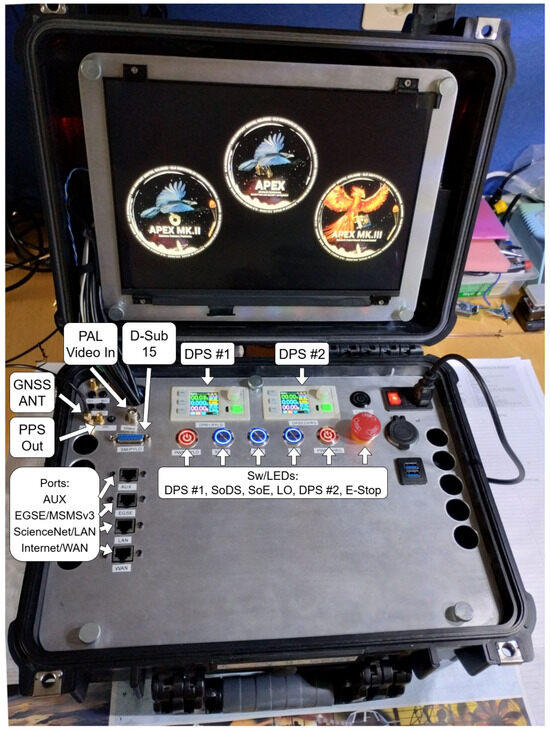
Figure 1.
apex Multi-Role Mission Support System with integrated Multiple Service Module Simulator v3.
2.2. MSMSv1
The development of the first MSMS, previously under the name “MAPHEUS Service Module Simulator”, began in 2018 as a byproduct of the first advanced processors, encryption, and security experiment (apex) design. As this was the first experiment to be developed at the German Aerospace Center (DLR) Microgravity User Support Center (MUSC) to fly on the Material Physics Experiments Under Microgravity (MAPHEUS) sounding rocket, testing capabilities needed to be established to allow for SM Interface validation prior to an official bench test at the Mobile Rocket Base (MORABA) facilities. Due to these tests, issues could be found and corrected early in the development process, helping to avoid costly retrofits and preventing potential damage to the payload or SM. An additional bonus was the possibility of including automated checks. The software for the first apex did not have any flight heritage yet, was changed frequently, and only used in synthetic—human operated—tests during normal working hours.
One of the most important aspects of any experiment is the reliability of the overall system. This was proven to be the case since the first apex campaign only had about 6 min of microgravity in which the experiments could take place and also had no TM/TC system for human intervention in case of issues. Finally, all experiment steps were controlled by inputs of the SM signal lines and needed to be interpreted correctly and reliably by the apex.
The last important point was that the main computer of the first apex was a Raspberry Pi (RPi) Zero W (Raspberry Pi Foundation, Cambridge, UK), which uses a µSD card for storage. As the system could not be safely shut down before power off, data corruption and the possibility that the system would fail to boot became likely. To counteract this issue, the operating system employed was booted from a read-only partition, which is designed to prevent corruption during an unexpected power failure. The data partition was hardened as well and should only lose about 30 s to 1 min of data recording after power off and restore itself if the system suffered substantial damage. At the start of the project, system hardening was by design only and not backed by prolonged test campaigns.
With those requests in mind, it became clear that extensive automated testing was needed. The plan was to build a hardware simulator that could replicate the interface of the MAPHEUS SM and outfit it with the capabilities to run automated simulated rocket flights, e.g., simulating power and signals in correct intervals and dependence.
Additionally, the system should be able to simulate the TM/TC interface, which was not useable during the first apex campaign due to interface overbooking at the SM but useful in tests to let the simulator know when a successful boot of the apex On-Board Computer (OBC) had taken place.
2.2.1. REXUS Service Module Interface
Because there is currently no open publication available describing the capabilities of the MAPHEUS SM, the definition of the simulator interface will be explained by using the technically similar but simpler REXUS Service Module (RXSM) of the Rocket-borne Experiments for University Students (REXUS) microgravity system as described in the publicly available manual [10]. Relevant information will be presented below, including the corresponding chapter designations from the user manual in parentheses.
The RXSM exposes its services towards a payload by two physical interfaces: a D-SUB 15 pin male connector for all electrical and data connections (7.7.1) alongside an optional Bayonet Neill Concelman (BNC) connector, which ingests a standard Phase Alternating Line (PAL) (B/G) with 1 Vss at 75 Ohm video signal (4.1.3) for live video transfer to the ground.
Power is separated into two categories: Experiment/Payload and Charging. Experiment power is defined at a standard 28 V Direct Current (DC), but since it is directly delivered from the on-board batteries, the voltage can vary between 24 and 36 V. The experiment is allowed to draw a mean current of 1 A, resulting in a total consumption of ∼30 W. During switch on, the peak current draw should not exceed 3 A. Experiment power is supplied until shortly after landing (7.7.4). Charging power is optional and can be added in case the experiment has on-board battery systems that need to be re-charged during RXSM shutdown. This interface is also defined at 28 V DC and 1 A (7.7.5).
Moving to the signals and control interface, the RXSM allows up to three signal lines attached to the experiment to inform it about different flight events (7.7.6). Lift Off (LO) is a universal signal shared between all experiments, given as soon as the rocket leaves the launcher, and reset after touchdown. Start/Stop of Data Storage (SoDS) and Start/Stop of Experiment (SoE) are experiment-specific and can be set and reset in accordance with the needs of the individual experiment. The signals can be set either by timeline or commanded during the flight. In most use-cases, at least one of these signals is used to inform the experiment of the start and end of the microgravity phase. Electrically, they are designed around an open collector output tied to the 28 V/GND of the experiment power interface (7.7.6).
The last interface is the TM/TC. It is defined as a 38,400 baud RS-422 serial line using a 1 kΩ termination resistor on both up- and downlink (7.7.2, 7.7.3, 7.7.7).
2.2.2. Implementation
The first MSMS was created during the initial apex hardware assembly and, like apex, was built by hand on perfboard to allow for quick modifications. It used an Insulation Displacement Connector (IDC) instead of the required male D-Sub 15 connector since the apex was not directly connected to the SM but via an internal connection to the CellFix II experiment [11]. Charging power was not needed; so, MSMSv1 only exposed payload power in the form of a programmable RS485 connected Digital Power Supply (DPS) 5005 (Joy-IT, Neukirchen-Vluyn, Germany) [12] fed by a 48 V, 1 A Cisco Power over Ethernet (PoE) power brick. For signals, a control circuit using a four port optocoupler and assisting transistors were furnished to allow switching by a 3.3 V Transistor–Transistor Logic (TTL) level system. Finally, the RS-422 interface was realized using a high-speed RS-422 to RS-232 3.3 V TTL level driver and the needed termination resistor. The overall system was controlled by a RPi Zero W, which was outfitted with a USB hub, USB Ethernet controller, and USB RS485 interface to connect to the Modbus-controlled DPS 5005. A video capture card was not included in this first iteration. See Figure 2 for the block diagram.
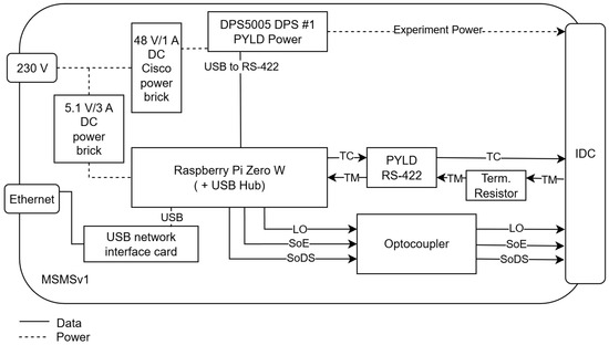
Figure 2.
apex MAPHEUS Service Module Simulator v1.
2.2.3. Results
The MSMSv1 was quite limited in features and mainly catered towards long-time simulations and support during checks. Simulations were written in Bourne-Again Shell (BASH) scripts and enabled the system to mimic rocket signals and voltage decrease over the flight period until a complete power cut was triggered at the end of the simulation with a minute of following downtime. The RS-422 interface could receive the “power-up” message after a successful apex boot on a subsequent run and log the simulation as satisfactory. Even though this setup seems quite simple, it should not be underestimated how useful the automated simulations of more than 100 flights outside of regular working hours were. It allowed finding specific issues in the initial design of the apex, especially rare occurring problems with filesystem mounting and data persistence. It also allowed for long-time stress testing under vacuum conditions. As the TM/TC system could not be used during flight due to interface overbooking, it was not yet developed to the same quality as the ones of following apex experiments and simulators.
2.3. MSMSv2
The MSMSv2 began development as part of the second generation of apex experiments, namely the apex Mk.2 Science Camera Platform (SCP) and the apex Mk.3 Student Experiment Sensorboard (SES) in mid-2019.
2.3.1. Implementation
In contrast to the first generation, MSMSv2 was already built using a Printed Circuit Board (PCB) and tried to evolve towards a simulator catering to all MAPHEUS payloads—and not only apex—by allowing all SM interfaces to be simulated. To save space and match the apex Mk.2 and Mk.3 interfaces, it still used the 16 pin IDC instead of the D-Sub connector. In regards to the power interface, it had the option to include two DPS 5005 to allow for both experiment and charging power to be simulated, though both were supplied by the limiting Cisco PoE power brick. It also used all four channels of the optocoupler and allowed the free configuration of the fourth channel using jumpers. The RS-422 interface remained untouched. A significant improvement was the breakout of payload data, signal, and different power pins via 2.54 mm pin headers in addition to the RPi standard header interface, which allowed for easier manual switching of signal lines during ground reference experiments. The RPi Zero W was upgraded to an RPi 4B, and the software stack was improved (see Figure 3). Finally, a video capture card was added to allow for reference recordings, flight-like simulations, and operator training.
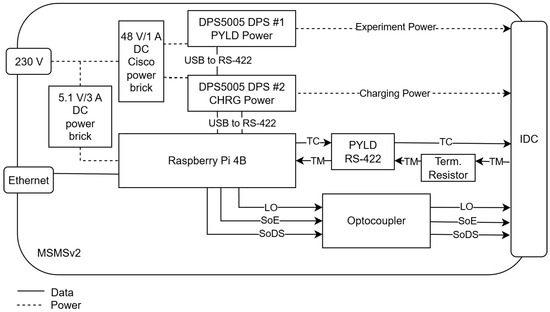
Figure 3.
apex MAPHEUS Service Module Simulator v2. Not shown: the video grabber implementation with an additional Raspberry Pi 4B.
2.3.2. Results
The MSMSv2 was a significant step-up from its predecessor, not only in appearance but also in functionality. While control of the system would still be feasible via BASH scripts, the MSMSv2 was integrated into the Mission Control System (MCS) Yamcs (Space Applications Services (SAS), Belgium)—including control of power, signals, and TM/TC. This allowed a complete flight-like simulation using the complete MCS stack and operator displays. It also allowed for more flexible configuration of simulations, as all timelines were now scripted within the Yamcs Studio operator displays and could be timed using a self-created countdown clock simulator behaving like the real Swedish Space Corporation (SSC) timer.
Like MSMSv1, MSMSv2 was used heavily for automated testing, as well as for developing the CCSDS compatible Space Packet [13] TM/TC interface. It proved invaluable during operator training and for conducting ground reference experiments with apex Mk.2 and its biological samples.
Still, MSMSv2 had several drawbacks: the missing D-Sub 15 connector, the untidy connection of the DPS 5005 via RS485 USB interfaces, the underpowered power brick, as well as the direct integration into Yamcs, all of which were not yet satisfactory.
Overall, MSMSv2 was missing a separation from the MCS backend and the option to easily integrate it with other well-known tooling, like National Instruments LabVIEW, to allow for more flexibility and user choice.
2.4. MSMSv3
After conclusion of the second generation apex flight, development of the third generation of experiments started in early 2022. As the MSMSv2 platform had been kept very open and modular, it was possible to add most of the changes in the form of an adapter board sitting piggyback on the RPi standard header interface. With this approach it was possible to quickly test and improve changes before the new design was finalized in a new PCB.
2.4.1. Implementation
MSMSv3 (Figure 4) finally introduced the required D-Sub 15 connector as the main interface and dropped the IDC.
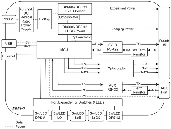
Figure 4.
apex Multiple Service Module Simulator v3.
The optocoupler was kept in the four channel configuration with the breakout of most pins as already seen on MSMSv2.
The RS-422 interface retained its proven driver, though the termination resistor was swapped from a fixed one to a software-defined one. With that, the resistance could be set via configuration flags in case simulations for SMs with other termination requirements were flown. The control of this resistor and the overall MSMSv3 was finally changed from an RPi to an on-board Microcontroller Unit (MCU). The reason for this step was to decouple the MSMS from its dependence on additional systems, give it more autonomy, and allow manual control by an operator.
To that end, the system gained a port expander, which allowed up to eight switches, all with their own control/status Light Emitting Diode (LED), to be added. With these switches, SM signals could be set and reset, the DPS powered on/off, and the state of the newly added emergency stop switch surveyed. Depending upon MCU configuration, the DPS would be automatically set to the correct voltage and current values, and the operator could just switch the power lines on/off, while the DPS itself remained locked for manual changes. Alternatively, the DPS could be completely unlocked and configured in detail using its own switches.
To allow for this kind of control, the DPS was connected to the MCU using an asynchronous Modbus interface. Its asynchronous nature allowed the use of multiple DPSs without overpowering the MCU. The connection between the DPS and MCU was accomplished using an opto-isolator to safeguard both systems from electrical failures or ground loops. To improve upon the DPS performance, a second driver was implemented to allow the use of the newer RK6006 DPS (Hangzhou Ruideng Technology Co., Ltd., Hangzhou, China) series instead of the proven DPS5005. A comparison of both DPSs can be found in Table 1, including a reference to their datasheets. While the RK6006 does not technically support a direct TTL level RS485 connection, reverse engineering of its physical interface and fabrication of a special wiring harness enabled this operations mode in the end. The driving factor for choosing the RK6006 over the DPS5005 was its faster RS485 driver, which could be interfaced with 115,200 baud instead of 19,200 baud. While changing the DPS, the power budget was improved by upgrading the Cisco PoE 48 W power brick to a medical safety-approved (2x MOPP) 90 W power supply.

Table 1.
Comparison of used DPS.
For more flexibility, the MSMSv3 supports two different MCUs—the RPi RP2040 backed WIZnet W5500-EVB-Pico (WIZnet Co., Ltd., Seongnam-Si, Republic of Korea) or the NXP iMXRT1062 backed PJRC Teensy 4.1 (PJRC, Portland, OR, USA). Both software and PCB design allow for a quick swap depending upon the users’ needs: either the 2x 133 MHz multi-core capabilities of the RP2040 or the 1x 600 MHz single-core of the iMXRT1062. As the latter MCU additionally allows for cryptographic signing of firmware, firmware encryption, and protection from unauthorized firmware upgrades, it became the standard MCU for the MSMSv3. Nevertheless, there might be future experiments using the newer RPi RP2350 based WIZnet W6300-EVB-Pico2, as those are pin compatible with the current PCB design and allow for early adaption of RISC-V MCU architecture.
Control over the MCU is taken either via Universal Serial Bus (USB) or Ethernet interfaces using the SCPI protocol. SCPI allows for effortless communication with MSMSv3 using human readable commands, e.g., OUTPut:STATe:PYLD ON to enable payload power. Commands can be abbreviated (OUTP:STAT:PYLD ON), and multiple commands can be chained using a semicolon (OUTP:STAT:PYLD ON; MEASure:VOLTage:PYLD?) to create more complex command sequences. The main advantage of SCPI lies in its standardization in 1990, widespread use in lab equipment, and subsequent inclusion in all relevant lab tooling. This includes National Instruments LabVIEW, MathWorks MATLAB, and Simulink, as well as the MCS Yamcs from Space Applications Services (SAS). Due to this, MSMSv3 can be easily integrated into existing setups and run along established experiment control software. This allows for efficient and cost-effective simulations and development support.
The drawback of SCPI is its nature as a polling protocol in its most basic form. To allow for easier updates of all available MSMSv3 parameters, without having to poll all of them individually, the special command TELEmetry:JSON? has been created to allow the system to report all current parameters as one JavaScript Object Notation (JSON) list for faster and easier data exchange.
The difference between USB and Ethernet interface lies in their usage scenario: While USB only allows SCPI access (e.g., for initial configuration or for power and signal switching), Ethernet adds the possibility of receiving and sending payload TM/TC via the RS-422 driver and allows optional auxiliary data via its AUX interface.
In contrast to previous generations, MSMSv3 now uses the standard D-Sub 15 connector and a medical-grade 90 W supply, addressing earlier limitations. Moreover, SCPI compatibility ensures integration not only with Yamcs and Python workflows but also with National Instruments LabVIEW, allowing users to incorporate the simulator into established laboratory environments.
The AUX interface and its AUX Node is another new feature and facilitates additional sensors or actors to be included within the MSMS data streams. The AUX interface is a high-speed RS-422 interface with a 5 V DC power line, exposed via a Registered Jack (RJ)45 connector. Due to this connector choice, standard shielded networking cable of varying lengths can be used to connect to the AUX Node. The AUX Node itself is a small PCB, holding the RJ45 connector, RS-422 driver, as well as a Low-Dropout (LDO) voltage regulator, regulating the ∼5 V DC to stable 3.3 V and making this voltage available to both the RS-422 driver and additional customer provided MCUs and sensors.
The AUX Node, as seen in Figure 5, is meant to act as an interface board allowing the addition of temperature, vibration, or other sensors to the MSMS as auxiliary data, which would be recorded during specific lab testing, including vacuum and shaker tests. This allows documenting payload performance under these stress situations without having to include the needed sensors into the payload hardware and TM/TC subsystem. The AUX Node data are made available transparently at the MSMS, the same way the SCPI interface and the payload TM/TC are, via their own ports as bidirectional User Datagram Protocol (UDP) streams.
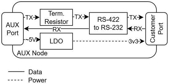
Figure 5.
apex Multiple Service Module Simulator v3 AUX Node.
The seamless integration of power and signal controls within MSMS via the manual switches and LEDs using the port expander and the software control via SCPI allow an operator constant awareness of the system state and seamless operation using both interfaces. The open design of the MSMSv3 and exposed additional ports promote future expansions like the integration of hardware cryptography modules and other additions.
2.4.2. Electrical Safety
To safeguard both the tested payload and operator, additional security features have been implemented within MSMSv3. While the simulator was using 5 kV isolated optocouplers and 20 kV Electrostatic Discharge (ESD)-protected RS-422 drivers due to its MAPHEUS heritage, the power system was redesigned with safety in mind. A fused 230 V input, proper grounding of all components, and the installation of a medical safety-approved (2x MOPP) 90 W power supply began this upgrade. The next step was the installation of an E-Stop between this power supply and the input of the DPS. This position meant that in case of an emergency shutdown the DPS would not be able to draw additional power from the capacitors of the power supply and shut off more quickly. The E-Stop also has an isolated signal line attached to the port expander, so that the simulator will be informed of this issue.
As already mentioned, connection of the DPS to the MCU was also handled with opto-isolators to avoid potential ground loops—and the constant communication also shields the payload under testing from harm. This can be stated due to the fact that the DPS controls will be locked while the simulator is actively communicating with it. That means that the DPS settings can only be changed via MSMSv3 or powered on/off at any time by using the buttons connected to the port expander. This restriction is in place to safeguard a payload from an operator switching on the payload with too high voltage or current limits.
This safeguard stands because the MSMSv3 will always load a vehicle-specific pre-defined profile, e.g., MAPHEUS. Within this profile, maximum voltages and currents alongside values for over-current protection and over-voltage protection can be defined. The MSMSv3 will then check each operator input for these maximums and only apply a change to the DPS if it is within defined range. It will also program the DPS with over-voltage protection and over-current protection values to make sure the hardware stays safe even within a short circuit event. Additionally, before each power on of a DPS output, the MSMSv3 checks again with the DPS to ensure that it is properly locked and all settings are in range. This feature leads to slower switch times (e.g., 325.179 ms on switch on as will be shown later), but this limitation is considered worth the investment, considering the additional security. Last but not least, in case of an over-current event, the DPS itself will switch off the payload within a time window of ~0.437 ms and report to the MSMSv3.
2.4.3. Results
MSMSv3 improved upon all the drawbacks identified in the previous generation and went beyond the initial set targets. Due to the fact that the hardware grew so powerful that it could allow for simulation of more complex targets than the REXUS and MAPHEUS SMs, the meaning of the MSMS acronym has been changed from the initial MAPHEUS Service Module Simulator to the now current Multiple Service Module Simulator, describing that it became a more flexible and open simulation system for different payload platforms.
Subsequently, simulation capabilities for the Astrobotic Moon Lander series Standard Electrical Connector (SEC) and the SSC Suborbital Express platform were added. The Astrobotic SEC interface, as described on page 46 of their user manual [15], needed an additional circuit to provide Pulse Per Second (PPS) signals to allow for time synchronization of the payload. This additional interface was added using the capabilities of the MRMSS and included in the custom wiring harness to adapt the D-Sub 15 connector to the Peregrine using the Glenair SuperNine connector. With this, it was successfully used with a hardware simulator of the DLR M-42 payload for the Peregrine moon mission [16].
While MSMSv3 is already advanced, it still carries its legacy as a vehicle-specific simulator. This includes the specific amount and types of data, signals, and power interfaces, as well as the D-Sub 15 connector chosen to connect them to their simulation target. Though the given interfaces are industry standard, and their parameters (e.g., voltage/current limits, RS-422 termination resistance, RS-422 baud rate, among others) can be changed within the simulator as configuration items, adaptation of said interfaces to their needed physical connectors of another target is still necessary. On the other hand, the current interfaces with SCPI, integration of the AUX Node, CCSDS support, and the integration into the MRMSS are already well-defined and can be used if the current simulator interface load-out is already sufficient.
For future improvements, it is planned to decouple the system further and allow an easier adoption to a wider array of simulation targets by allowing a broader array of interface types and combinations to be added to the simulator. A roadmap will be provided in the conclusions of this study.
This decoupling could also come with the need to add more computational power back into the simulator to support the additional interfaces and configuration options. MSMSv3 in its current form provides a well-defined interface to all its subsystems and controls their functions so that they stay within the parameters allowed for the simulation at hand. The integration of more DPS, signals, TM/TC interfaces and their supervision will impact system performance and can only be counteracted by using patterns of distributed systems and multiple cores to allow for horizontal scaling and better extensibility.
2.5. MRMSS
While the Multiple Service Module Simulator (MSMS) role was clearly defined in being the SM simulator, it was not able to run complex simulations on its own. There was a need for additional computing power, user interfaces, and networking capabilities, which were not strictly part of the simulator but benefited it. With this need, the Multi-Role Mission Support System (MRMSS) was designed, a set of support hard- and software housed in a small and portable briefcase—alongside the MSMSv3 (see Figure 6).
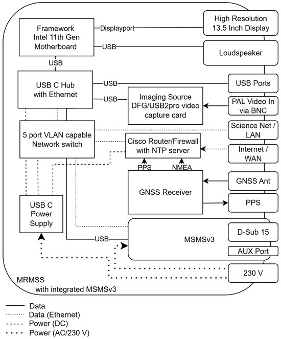
Figure 6.
apex Multi-Role Mission Support System with integrated apex Multiple Service Module Simulator v3.
The main role of the MRMSS started as a support tool for the MSMSv3, but it quickly evolved beyond that. The start point for the project was the re-use of the portable MCC [9] demonstrated during the MAPHEUS-10 mission for apex Mk.2 and Mk.3, which immediately gained the MRMSS capabilities beyond being used in the lab and for development, but also for real-time flight scenarios.
To support the software components, the top case includes a Framework Intel 11th Gen motherboard, a USB-C hub with networking interface, a 13.5 inch high resolution (2256 × 1504 pixel) display, speakers, and an Imaging Source DFG/USB2pro video capture card. The bottom case integrates a USB-C power supply, a Cisco router/firewall solution, a GNSS receiver with external antenna and PPS output, and a VLAN-capable managed switch. The GNSS receiver is also used as a source for the NTP time server running on the Cisco. Additionally, the complete MSMSv3 including three signal buttons with LED rings, two buttons with LED ring for manual control of the two DPS, two RK6006 DPS, one emergency power off button, and the power supply are included in the bottom case. According to the mission needs, additional features can be retrofitted, including an SDR solution to receive and decode weather balloon data and an LTE modem to achieve mobile connectivity, alongside other accessories like headsets, cameras, and cryptography tokens.
The MRMSS is capable of replacing all other tools needed to support a normal payload flight and ground reference campaign and can, if needed, also allow external scientists or engineers to secure remote control capabilities via its internal OpenVPN server and firewall.
Switching from one payload configuration to another is straightforward, due to its configuration loader, which allows mixing and matching the needed tools within a Yet Another Markup Language (YAML) configuration file that can be loaded upon request. Depending upon configuration, the overall MCS can be loaded with different inputs (direct serial connections, Network sockets, MSMSv3, etc.), routing (CCSDS Finite State Machine (FSM), Serial Line Internet Protocol (SLIP) protocol loaders, other protocol handlers, …), outputs (Yamcs Server, debug outputs, Wireshark, …), and additional tooling (data recorders, Grafana, Yamcs Packet Viewer, SSC Countdown Clock, Astrobotic Time Synchronization …).
In case of testing campaigns, MRMSS can use the MSMSv3 and its internal video capture card to give a flight-like simulation using the flight-hardware for operator training or hardware testing (see Figure 7). It can simulate automated timelines via the Yamcs Studio Displays and scripts to allow for repeated or automated testing. If need be, tailored AUX nodes can be used to gain additional insights into the flight hardware and measure additional parameters like temperatures of specific components or acceleration forces during shaker tests.
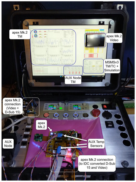
Figure 7.
apex MRMSS running a flight simulation for apex Mk.2. Also visible are three temperature sensors attached to vital points of apex Mk.2—integrated into MSMSv3 via the AUX Node.
Due to its software tooling, it is additionally capable of supporting the development of new payloads. It contains a data product generator, which allows the insertion of a simple CCSDS Space Packet format description and converts it to a Yamcs MCS Mission Database (MDB) alongside serialization and deserialization code in C and Python to be used in the flight hardware and on ground support equipment. With this tooling MDB, flight software and ground support software can be partially generated from the same description and allow quick turnaround times for faster integration of new sensors and experiments.
3. Results
Thanks to the series of MSMS and MRMSS precursors, the apex on MAPHEUS-8 in 2019 and the apex Mk.2 SCP and Mk.3 SES on MAPHEUS-10 in 2021 were successfully developed, tested, flown, and had their scientific data extracted—alongside the ground reference experiments conducted during that time span. The system also supported the DLR M-42 payload on Astrobotic Peregrine in 2024 in terms of simulation capabilities and data/flight recorder software.
The role of the MRMSS, especially in pre-launch checks, can be separated into multiple categories. The system is especially catered towards long-term reliability testing, allowing the introduction of stimuli over extended periods of time and the recording of the payload’s TM, power consumption, and other measurements via an attached AUX Node for later analysis. This helps with the initial check of the hardware after transportation to the launch site. The simulator also allows for ground reference experiments before launch for later comparison without additional hardware. However, the most important check during a pre-launch campaign is the flight simulation.
Using a programmed timeline, the MRMSS delivers stimuli towards the payload as it would receive during a real flight (with the exception of acceleration forces). This also includes varying factors such as depleting on-board batteries and, hence, decreasing payload supply voltage, which is not shown in the timeline seen in see Table 2.
Table 2.
Exemplary flightplan for a shortened countdown.
The timeline can then be used for both testing the hardware in repeated fully automated flight simulations as well as familiarization for an operator. In the later use case, the operator could train flying their payload and getting acquainted with the system. After basic certification, additional training can be applied, and errors can be programmed into the timeline, e.g., signals not arriving or abnormal voltage readings—allowing the operator to train for contingency operations. This is especially useful, as certain sounding rockets only offer microgravity times of up to 6 min, underlining the needed proficiency in resolving payload anomalies quickly and efficiently.
In addition to qualitative mission use, a series of quantitative benchmarks was conducted to assess the latency, signal timing, and power switching performance. Table 3 summarizes the results. At 460,800 baud, round-trip command/telemetry latencies remained stable across injection intervals from 500 ms down to 5 ms. Below 5 ms, queuing effects caused degraded reliability, making shorter cycles impractical. For comparison, 38,400 baud operation at 5 ms yielded complete integrity over 1000 telecommands with corresponding telemetry responses. Signal switching delays, measured from mechanical button actuation to electrical state change, averaged below 5 ms for both activation and deactivation (25 repetitions each). The power supply on/off responses were different with an average 325 ms for power on and 480 ms for power off. The relatively long switch times can be explained by the electrical safety mechanisms in place for the power on and with a missing test load for the power off test. The over-current protection, however, triggered with a favorable 0.437 ms on average. Finally, continuous telemetry stress testing at 4 Hz over >250,000 frames confirmed error-free operation, during a test time of more than 17.5 h of continuous operation.
Table 3.
Summary of quantitative benchmarks on MSMSv3.
Last but not least, tooling developed for the apex MCC is still in use to support the International Space Station (ISS) Electromagnetic Levitator (EML) experiment with real-time Two-Factor Authentication (2FA) Virtual Private Network (VPN) secured remote video and TM viewing capabilities. It also allowed for EML operations during the challenging COVID-19 pandemic.
4. Conclusions
The MSMS simulator has been in development alongside the apex experiments, which resulted in three simulator generations. It started as a small payload-specific automated testing tool and matured over the years to a more generalized simulator and accompanying support tooling that allowed flexible use during the complete lifecycle of a microgravity payload. With its increasing flexibility and added simulation capabilities, it grows even more useful and shall remain on this path.
Using its current design, it is already possible to use the simulator for payloads outside the sounding rocket area by using the existing interfaces and creating breakout cables for the intended payloads. For CubeSat payloads, connecting to an RS-422 powered on-board computer [17], only the RS-422 termination resistance, power profile, and MDB configuration need to be changed. If larger payloads with more complex power demands need to be tested, the modular power supply stage can be scaled or replaced. There is also the possibility of removing the RS-422 driver and bridging its connection to allow for direct RS-232 use. For the simulation of the Astrobotic Peregrine moon lander, the PPS interface of the MRMSS was used, and after building a breakout cable, adapting the MDB, and changing the interfacing scripts at link layer to allow their specific protocol, the system could be simulated. These examples illustrate the broad applicability of the system beyond MAPHEUS heritage.
Several practical limitations remain. The current default profiles are still MAPHEUS-derived, requiring manual reconfiguration for other platforms. The system is designed for laboratory use and does not incorporate Electromagnetic Compatibility (EMC) hardening. The included 90 W supply covers standard payloads, but higher power levels require replacement of the power stage. Furthermore, on-board computational resources remain limited compared to the MRMSS, restricting closed-loop test scenarios.
For future developments, a more universal approach and easier extension of capabilities (more signals, power channels, data channels) need to be taken into account to allow for more complex simulation targets to be supported. As stated before, the key to a more generalized system will be to add additional computational power to the MSMS and allow for additional modularization. Instead of having only a limited number of hard-wired interfaces already bound to standard interface socket, a flexible configuration would be needed. This can be achieved by defining modular blocks for the most used interface types (e.g., signals, power, RS-232, RS-422, RS-485, Inter-Integrated Circuit (I2C), Serial Peripheral Interface (SPI), Controller Area Network (CANbus), among others) and allowing the customer to assemble their configuration as needed. Giving each of these blocks their own computational power, tying them together via ethernet, and managing them via a central control system will allow to create a high-speed, modular, and tailored simulator, customized to the users’ needs.
Future developments will also target compatibility with the Micro-Experiments On Sounding Rockets As Insert Cubes (MOSAIC) module, which provides power and event signaling for CubeSat-sized payloads (1U/2U) but differs from the MAPHEUS service module in both voltage domains and signal conventions. Extending the simulator to MOSAIC will enable realistic pre-flight testing of CubeSat-class hardware. Recently flown payloads, such as the MiniFix fixation system [18], would directly benefit from such capabilities, as rapid hardware iterations can then be validated against both MAPHEUS and CubeSat-specific service modules in the laboratory.
Finally, the next steps also include the further improvement of the data product generator, configuration loader, and development of an independent timeline simulator to allow for even more complex simulations.
Author Contributions
Conceptualization, N.M. and S.F.; methodology, N.M.; software, N.M.; validation, N.M. and S.F.; formal analysis, N.M.; investigation, N.M.; resources, J.-P.d.V.; data curation, N.M.; writing—original draft preparation, N.M.; writing—review and editing, N.M., S.F. and J.-P.d.V.; visualization, N.M.; supervision, N.M.; project administration, N.M.; funding acquisition, J.-P.d.V. All authors have read and agreed to the published version of the manuscript.
Funding
This research received no external funding.
Institutional Review Board Statement
Not applicable.
Informed Consent Statement
Not applicable.
Data Availability Statement
The original contributions presented in this study are included in the article. Further inquiries can be directed to the corresponding author.
Acknowledgments
We want to thank the Institute for Frontier Materials on Earth and in Space at DLR Cologne for vacuum testing as well as allowing us to fly on MAPHEUS-10. We also want to express our gratitude towards MORABA for flight certification of the hardware, campaign, and on-site support with the Swedish Space Corporation (SSC) at Esrange. We also want to thank the DLR Institute of Aerospace Medicine, Department of Radiation Biology (Thomas Berger) for supporting the Astrobotic simulation capabilities by providing a Glenair SuperNine connector spare. This work was accomplished under basic funding by the DLR Microgravity User Support Center (MUSC) and the DLR Institute of Aerospace Medicine, both in Cologne, Germany.
Conflicts of Interest
The authors declare no conflicts of interest.
Abbreviations
The following abbreviations are used in this manuscript:
| 2FA | Two-Factor Authentication |
| apex | Advanced Processors, Encryption, and Security Experiment |
| BASH | Bourne-Again Shell |
| BNC | Bayonet Neill Concelman |
| CANbus | Controller Area Network |
| CCSDS | Consultative Committee for Space Data Systems |
| DC | Direct Current |
| DPS | Digital Power Supply |
| DLR | German Aerospace Center |
| EGSE | Electrical Ground Support Equipment |
| EMC | Electromagnetic Compatibility |
| EML | Electromagnetic Levitator |
| ESD | Electrostatic Discharge |
| FSM | Finite State Machine |
| GNSS | Global Navigation Satellite System |
| ICD | Interface Control Document |
| IDC | Insulation Displacement Connector |
| I2C | Inter-Integrated Circuit |
| ISS | International Space Station |
| JSON | JavaScript Object Notation |
| LDO | Low-Dropout |
| LED | Light Emitting Diode |
| LO | Lift Off |
| LTE | Long Term Evolution |
| MAPHEUS | Material Physics Experiments Under Microgravity |
| MCC | Mission Control Center |
| MCS | Mission Control System |
| MCU | Microcontroller Unit |
| MDB | Mission Database |
| MORABA | Mobile Rocket Base |
| MOSAIC | Micro-Experiments On Sounding Rockets As Insert Cubes |
| MRMSS | Multi-Role Mission Support System |
| MSMS | Multiple Service Module Simulator |
| MUSC | Microgravity User Support Center |
| OBC | On-Board Computer |
| PAL | Phase Alternating Line |
| PCB | Printed Circuit Board |
| PoE | Power over Ethernet |
| PPS | Pulse Per Second |
| REXUS | Rocket-Borne Experiments for University Students |
| RJ | Registered Jack |
| RPi | Raspberry Pi |
| RXSM | REXUS Service Module |
| SAS | Space Applications Services |
| SCP | Science Camera Platform |
| SCPI | Standard Commands for Programmable Instruments |
| SDR | Software Defined Radio |
| SEC | Standard Electrical Connector |
| SES | Student Experiment Sensorboard |
| SLIP | Serial Line Internet Protocol |
| SM | Service Module |
| SoDS | Start/Stop of Data Storage |
| SoE | Start/Stop of Experiment |
| SSC | Swedish Space Corporation |
| SPI | Serial Peripheral Interface |
| TC | Telecommand |
| TDD | Test-Driven Development |
| TTL | Transistor–Transistor Logic |
| TM | telemetry |
| UDP | User Datagram Protocol |
| USB | Universal Serial Bus |
| VPN | Virtual Private Network |
| YAML | Yet Another Markup Language |
References
- McGregor, J. Test Early, Test Often. J. Object Technol. 2007, 6, 7–14. [Google Scholar] [CrossRef][Green Version]
- Ferri, P.; Sørensen, E.; Nesbit, M.; Noyes, J. Towards a common check-out and control system for Rosetta. ESA Bull. 1998, 94. Available online: https://www.esa.int/esapub/bulletin/bullet94/FERRI.pdf (accessed on 4 August 2025).
- Metodi, T.S. Space Vehicle Testbeds and Simulators Taxonomy and Development Guide; Technical Report; Space and Missile Systems Center: El Segundo, CA, USA, 2010. [Google Scholar]
- Gagnier, D.; Hayner, R.; Roza, M.; Nosek, T.; Razzaghi, A.; Hendershot, J. Testing of Environmental Satellite Bus-Instrument Interfaces Using Engineering Models. In Proceedings of the Space 2004 Conference and Exhibit, San Diego, CA, USA, 28–30 September 2004; p. 5955. [Google Scholar]
- Choi, K.K.; Maral, G.; Rumeau, R. Space link simulator for development of a new standard CCSDS file delivery protocol. In Proceedings of the 1999 IEEE Aerospace Conference. Proceedings (Cat. No. 99TH8403), Snowmass, CO, USA, 7 March 1999; Volume 5, pp. 183–191. [Google Scholar]
- de Souza, K.V.; Bouslimani, Y.; Ghribi, M.; Boutot, T. On-board computer and testing platform for cubesat development. IEEE J. Miniaturization Air Space Syst. 2023, 4, 199–211. [Google Scholar] [CrossRef]
- Jones, M.; Melton, B.; Bandecchi, M. Teamsat’s low-cost EGSE and mission control systems. ESA Bull. 1998, 95, 139. [Google Scholar]
- Maas, N.; de Vera, J.-P.; Schmidt, M.J.; Reimann, P.; Randall, J.G.; Feles, S.; Hemmersbach, R.; Schierwater, B.; Hauslage, J. apex Mk.2/Mk.3: Secure live transmission of the first flight of Trichoplax adhaerens in space based on components off-the-shelf. Eng 2025, 6, 241. [Google Scholar] [CrossRef]
- Maas, N.; Feles, S.; de Vera, J.P. The apex MCC: A blueprint of an open-source, secure, CCSDS compatible ground segment for sounding rocket, CubeSat, and small lander missions. Eng 2025, 6, 246. [Google Scholar] [CrossRef]
- Lesch, K.; Völk, S. REXUS User Manual v.7.17; DLR: Oberpfaffenhofen, Germany, 2021; Available online: https://rexusbexus.net/wp-content/uploads/2021/12/RX_UserManual_v7-17_26Nov21.pdf (accessed on 4 August 2025).
- Liemersdorf, C.; Lichterfeld, Y.; Hemmersbach, R.; Hauslage, J. The MAPHEUS module CellFix for studying the influence of altered gravity on the physiology of single cells. Rev. Sci. Instrum. 2020, 91, 014101. [Google Scholar] [CrossRef] [PubMed]
- Joy-IT. DPS5005 Power Supply Datasheet; JOY-IT: Neukirchen-Vluyn, Germany, 2025; Available online: https://joy-it.net/files/files/Produkte/JT-DPS5005/JT-DPS5005_Datasheet-EN_2025-05-21.pdf (accessed on 4 August 2025).
- CCSDS. CCSDS 133.0-B-2 Space Packet Protocol. 2020. Available online: https://ccsds.org/Pubs/133x0b2e2.pdf (accessed on 4 August 2025).
- Hangzhou Ruideng Technology Co., Ltd. RK6006/RK6006-BT Power Supply Manual; Hangzhou Ruideng Technology Co., Ltd.: Hangzhou, China, 2024; Available online: http://www.ruidengkeji.com/inst/RK6006.pdf (accessed on 4 August 2025).
- Astrobotic. Astrobotic Lunar Landers Payload User’s Guide v.5.0; Astrobotic: Pittsburgh, PA, USA, 2021; Available online: https://www.astrobotic.com/wp-content/uploads/2022/01/PUGLanders_011222.pdf (accessed on 4 August 2025).
- Lenz, K.; Berger, T. M-42 Radiation Detector Flies to the Moon. 2024. Available online: https://www.dlr.de/en/latest/news/2024/m-42-radiation-detector-flies-to-the-moon (accessed on 4 August 2025).
- Endurosat. CubeSat Onboard Computer. 2025. Available online: https://www.endurosat.com/products/onboard-computer/ (accessed on 4 August 2025).
- Feles, S.; Keßler, R.; Hauslage, J. Pioneering the Future of Experimental Space Hardware: MiniFix-a Fully 3D-Printed and Highly Adaptable System for Biological Fixation in Space. Microgravity Sci. Technol. 2025, 37, 22. [Google Scholar] [CrossRef]
Disclaimer/Publisher’s Note: The statements, opinions and data contained in all publications are solely those of the individual author(s) and contributor(s) and not of MDPI and/or the editor(s). MDPI and/or the editor(s) disclaim responsibility for any injury to people or property resulting from any ideas, methods, instructions or products referred to in the content. |
© 2025 by the authors. Licensee MDPI, Basel, Switzerland. This article is an open access article distributed under the terms and conditions of the Creative Commons Attribution (CC BY) license (https://creativecommons.org/licenses/by/4.0/).