2.1. System Design
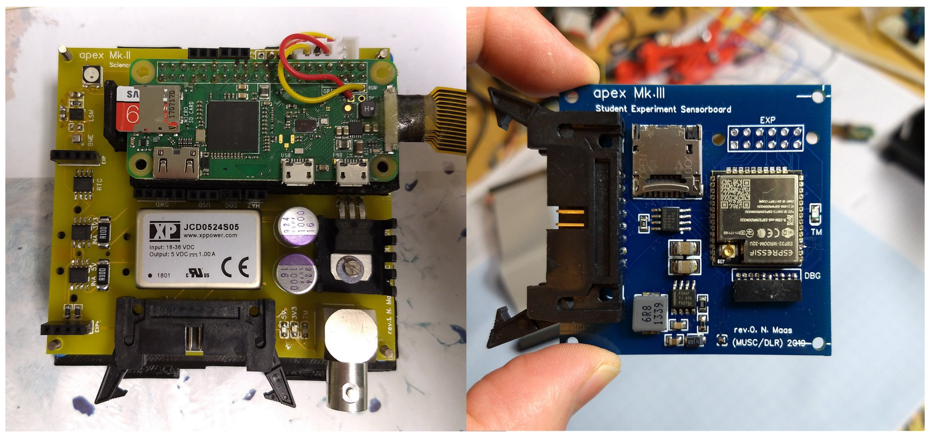
Starting off with the simpler system, the Mk.3 SES ESP32 was used in the original apex to provide the instrumentation to the original camera system: two Espressif ESP32-PICO-D4 (Shanghai, China) MCUs each having their own 32 GB SD card, card interface reset circuitry, an internal SPI Flash Filesystem (SPIFFS) memory as low-frequency emergency data recorder, and a synchronization bus. This allowed for redundant sampling of the Inter-Integrated Circuit (I2C) sensor bus and recording environmental data like temperature, humidity, atmospheric pressure, acceleration, magnetic field, and rotation.
After the inaugural flight, recorded data showed that both MCUs sampled the same amount of data, logs on both the 32 GB SD cards and internal SPIFFS memory were intact, and the SD card interface reset circuitries were never triggered as no error occurred. This led to the conclusion that the resilient design worked as intended, but, for more cost-effective missions, a single Microcontroller Unit (MCU) with its own SD card and internal SPIFFS memory would be sufficient.
With that, the overall system was simplified to a single Espressif ESP32-WROOM-32U (Shanghai, China) module (240 MHz, 32 bit dual core MCU with multiple cryptographic extensions and an additional “Ultra Low Power” co-processor, 520 KB of RAM, 4 MB of Flash) and a 32 GB SD card.
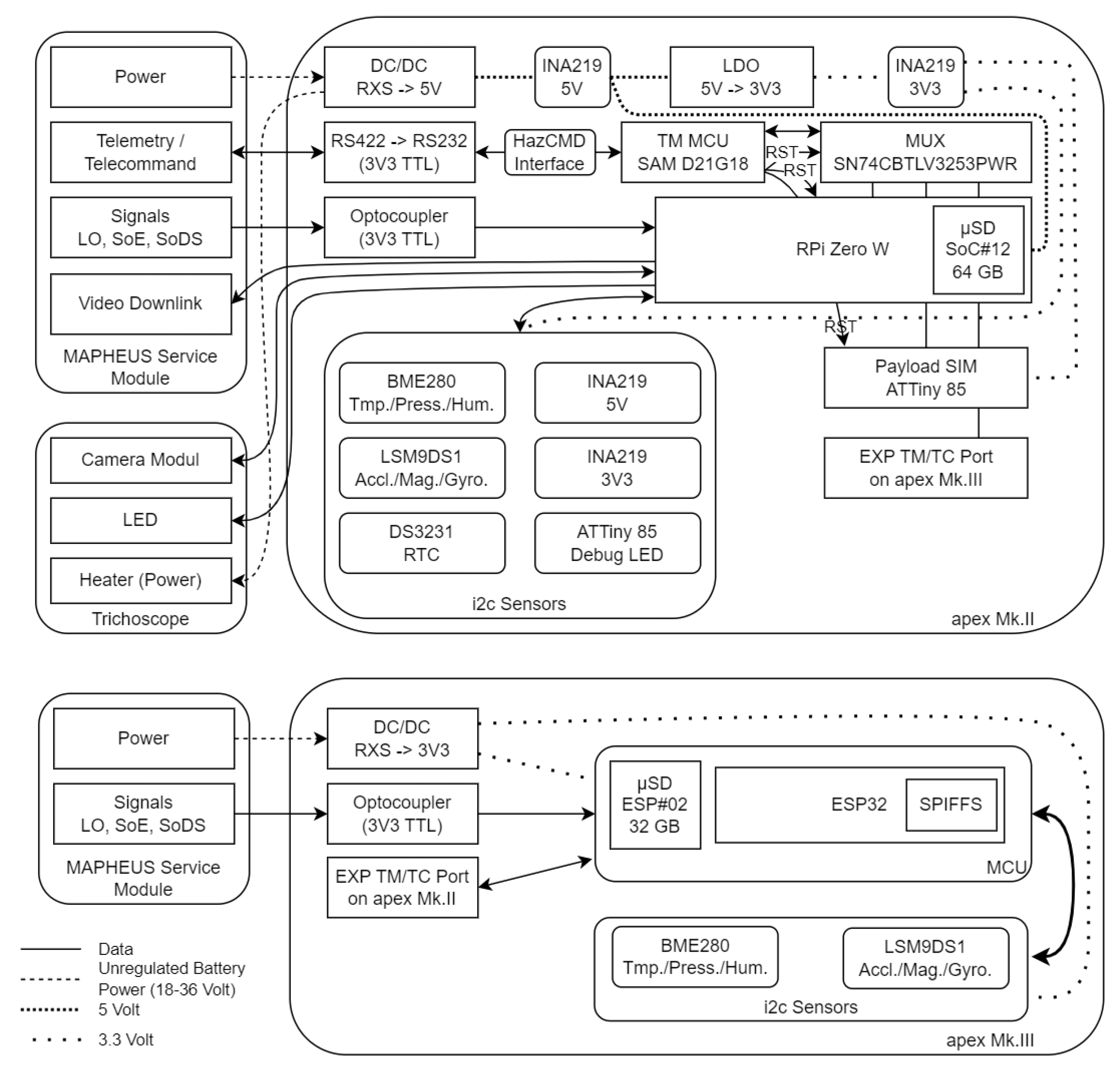
Additionally, a Low-Dropout (LDO) regulator, optocoupler, and RS422 converter were added. This allowed the new module to directly connect to power, signals, and TM/TC interfaces of the MAPHEUS Service Module, making the SES independent from its former mother payload. The reason for SES development lies in a request by the German Aerospace Center (DLR) Institute of Space Operations and Astronaut Training (RB) to create an Arduino-compatible board that could be used under microgravity conditions for training university students, small experiments, and qualification of sensor modules. SES achieves this by providing an open sensor bus, consisting of I2C, Serial Peripheral Interface (SPI), Universal Asynchronous Receiver/Transmitter (UART) and General-Purpose Input/Output (GPIO) connectivity, and a 3.3 V power interface—thus enabling rapid prototyping of simple experiments in a matter of hours. For a detailed overview, please see
Figure 2.
As an example, during the MAPHEUS-10 flight, SES was flown with the same environmental sensors already used during the initial campaign on MAPHEUS-8 but without a Real-Time Clock (RTC). As a reference to real world time, milliseconds since power-up of the board were recorded and used after the flight using the logged MAPHEUS Service Module signals.
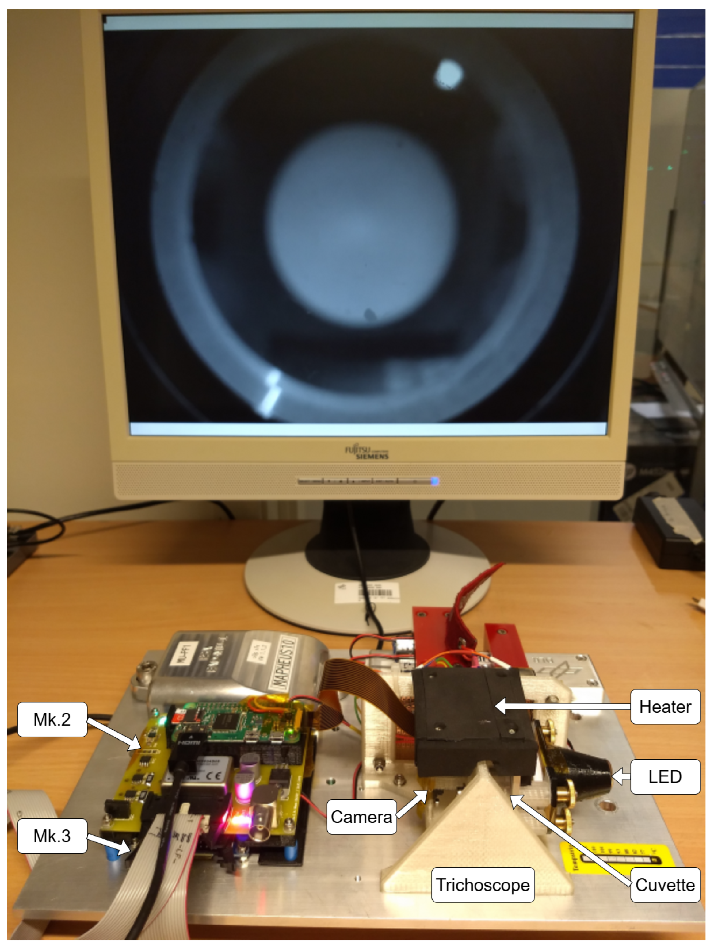
The Mk.2 SCP continued the tradition of the original apex project by focusing on real scientific application rather than just a technological demonstration, serving as the direct successor to the original camera subsystem. While it was still using the original small, lightweight, low-power, and high-performance Linux Single-Board Computer (SBC) RPi, Mk.2 performed significantly better due to changes regarding the Operating System (OS) used and overall composition of the payload. Starting with the signals and power system, both the flight-proven optocoupler for the service module signals and the DC/DC converter stages were re-used. However, other instrumentation changed: the original apex used multiple resistor dividers and a multichannel Analog–Digital Converter (ADC) to read out voltage levels. This had the drawback of lacking information about current consumption and thus missing overall power draw. To rectify this situation, Mk.2 replaced said ADC with power-gauges for the 5 V and 3.3 V power buses to allow for more precise monitoring of its power consumption. The resulting data was fed into the RPi, which now also directly ingested data of the environmental sensors previously handled by the redundant ESP32 configuration. This made Mk.2 directly and independently aware of its situation, which later proved to be of vital importance during the challenging MAPHEUS-10 campaign and its cold environment. To allow for more flexibility, Mk.2 also presented an open I2C bus in the form of an expansion slot that could accept different sensors to be retrofitted in the field. This could be used if additional sensors needed to be carried to space for certification or additional sensing capabilities were needed to improve scientific output of the specimen under observation (see
Figure 3).
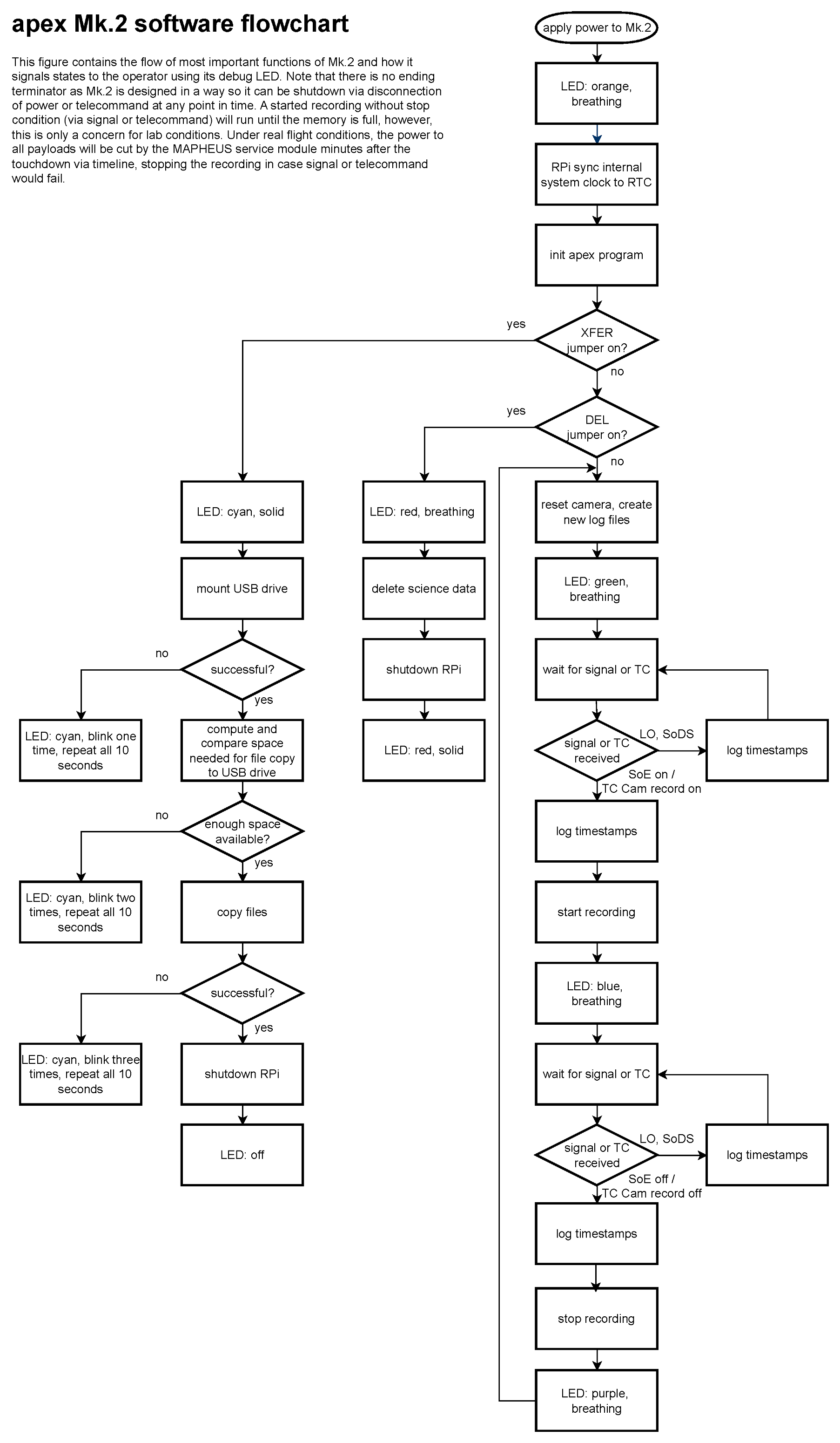
Having direct communication between the SBC and the I2C bus allowed the improvement of the operator handling of the system: A full Red–Green–Blue (RGB) Light-Emitting Diode (LED) with its own MCU and watchdog were added to show the current operations mode in an easily recognizable way (a more detailed schematic of the system composition can be seen in
Figure 2). With that, it was possible to distinguish if the Mk.2 was currently recording video data, resetting from a recording, or waiting for a signal to start the next observation phase. Having this feedback tool to interact with the operator during ground reference experiments led to adding additional jumper pins to trigger different functionality upon boot of the system. The original apex contained a jumper to allow the system to boot and erase its internal memory as a means for quickly resetting internal memory before start of a campaign—but had no possibility to show success or error to the operator. Mk.2 took over this DEL jumper and added error and success codes to its RGB LED system to improve the experience. It also elaborated on the overall workflow by adding an additional Transfer (XFER) jumper, which allowed the operator to prompt the Mk.2 to download all internal data onto an external Universal Serial Bus (USB) flash drive. With both those workflows in place, an operator in the field was able to download all the collected scientific data and reset Mk.2 with nothing more than a power source, flash drive, and jumper cable, as presented in
Figure 4. Among those two operator jumpers, a third one called Hazardous Commanding Switch (HAZ) was added and hints at the largest improvement—the added TM/TC subsystem.
While the original apex would have been able to talk to the MAPHEUS Service Module, this was not implemented due to the late addition of the payload to the launch manifest as well as an oversubscription of the service module. However, Mk.2 improved upon this by adding its own CCSDS-compatible TM/TC MCU and multiplexer. It also included a live video output to allow for direct downlink of a Phase-Alternating Line (PAL) preview video signal of the camera input via the service module. The video provided the scientist the advantage of judging the overall health of the specimen in real time. Meanwhile, the supplied environmental data via TM was beneficial for informed go/no-go decisions in challenging mission scenarios.
The TM/TC subsystem itself was a 32 bit ARM Cortex-M0+ Microchip ATSAMD21G18 MCU (Chandler, AZ, USA). It had access to the Mk.2 RPi Zero W (32 bit ARMv6), an Mk.2 MCU payload simulator (8 bit Microchip ATTINY85), and the Mk.3 payload (ESP32 with 32 bit Tensilica Xtensa LX6 Cores) via an added multiplexer. As mentioned, the complete communication was achieved using CCSDS-compatible space packets [
9]. This allowed for easier integration into current Mission Control Software (MCS) systems and to improve the reliability of communications. An extensive mix of different system architectures were used to prove that the developed firmware was architecture-independent.
The TM/TC subsystem was the main communications endpoint, serving additional uses: in case of issues, it had the capability to reset the payload simulator, RPi, and multiplexer on-board the Mk.2. The last but also most important function was that of a communications filter, which allowed the correct implementation of hazardous commanding capabilities.
In a space context, hazardous commands are TCs that might endanger the safety of an experiment, subsystem, payload, overall mission, or even human life. TCs can be hazardous by design or become hazardous depending on the situation. A good example of this is the reset of the Mk.2 RPi subsystem. While a simple reboot of the system on the ground might be an inconvenience, an accidental reboot during the microgravity phase of a real flight would mean loss of data. In case of an error with the RPi, the reset of the system might be the only chance of recovering the experiment to a functioning state, so there needs to be a way to trigger such a TC—here called “soft” hazardous command—by secure means. Other commands are only allowed during lab operations—for example, enabling radio communications of the RPi, which will be needed for synchronization of the dedicated RTC module or debugging purposes but never allowed on rocket; this would be a “hard” hazardous command.
In this solution, “soft” hazardous commands can be allowed by adding an additional bit flag before sending the command. On the operator displays, this is completed by using a toggle switch that needs to be armed before sending a “soft” hazardous command and resets automatically after each command. The TM/TC MCU checks on orbit if the command has any hazardous significance and whether the appropriate bit was set. If so, it forwards the TC to the receiver; otherwise, it rejects it with an error TM. The same principle applies for “hard” hazardous commands; however, there are two toggle buttons that need to be armed within the command displays, and the physical HAZ jumper on the Mk.2 must be in place. This is only the case during lab operations. Afterwards, the “Remove before flight” tag is pulled and the Mk.2 TM/TC system will reject any “hard” hazardous commands.
During regular operations, the TM/TC MCU was also used for quick ping tests and had a primitive scheduler that started acquisition of science TM of the Mk.2 RPi 45 s after initial power-on at pre-configured data rates. Other than reset or similar commands, the hazardous command system also allowed to adjust the illumination of the microscope, start/stop camera recording, or force the OS on the RPi to write any pending filesystem changes to disk.
Regarding the OS, the original apex used balenaOS, a specialized Linux OS that hosted the camera application and RTC functionalities within Docker containers. The downside of this decision was the small resource overhead needed to host those containers—and the larger resource requirements for balenaOS’s own management features. While this was still negligible during the first campaign, later iterations of balenaOS became more resource hungry due to advanced functionalities written in Node.js, so this choice was not feasible anymore. The switch was made to another open-source alternative, Yocto, which allowed to build a custom OS that left more resources to the actual application. By disabling all non-essential services and only running the Secure Shell (SSH) daemon, initial RTC synchronization, and the apex Python 3 application, we could achieve reliable and repeatable boot times of 30 s.
As storage media for both Mk.2 and Mk.3, Samsung Evo Plus
SD cards were chosen, as during the first campaign, due to their use during the ISS AstroPi program [
14] and their X-ray-proof, waterproof, and magnetism- and heat-resistant design.
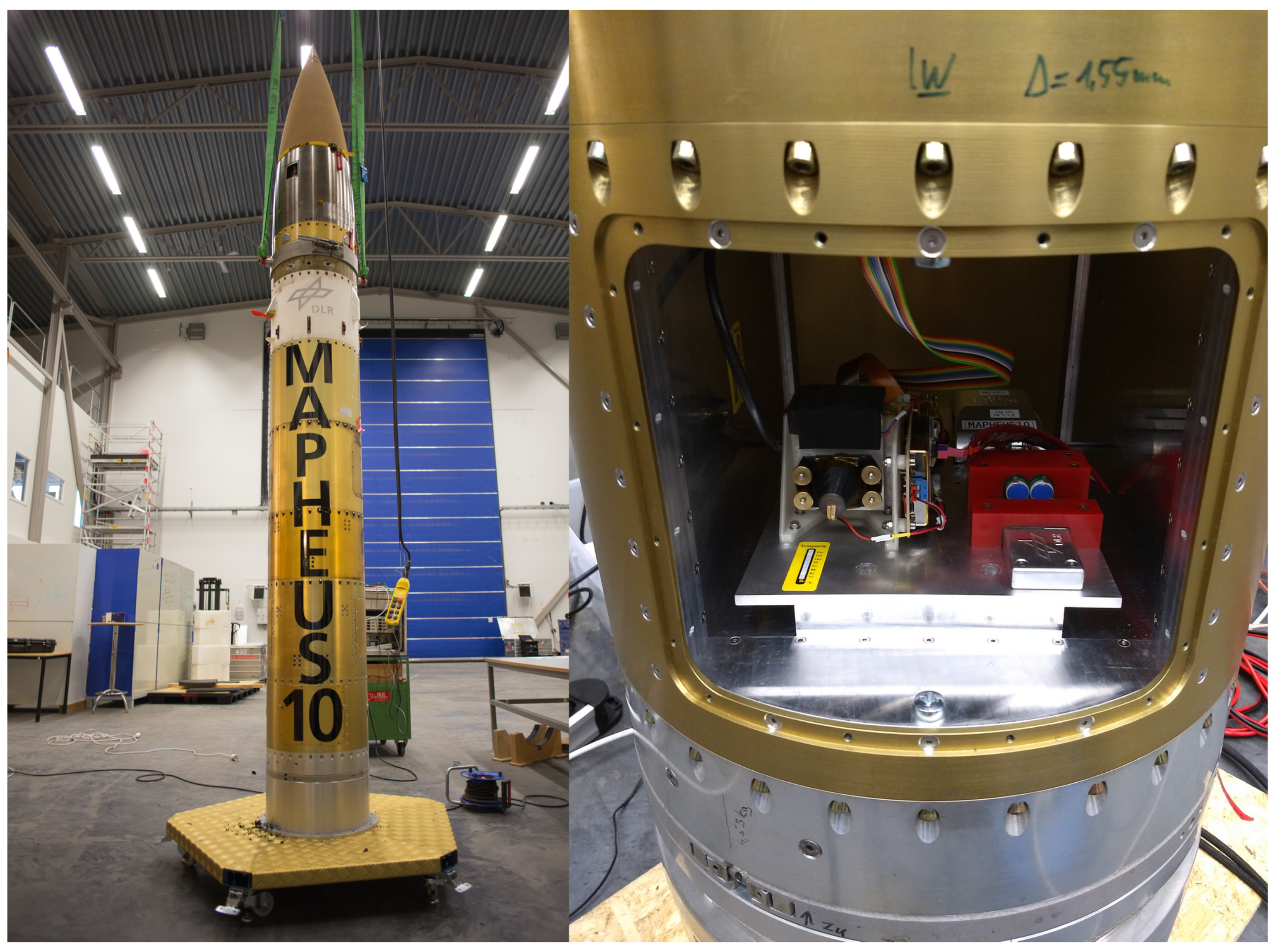
Both payloads used printed Fused Deposition Modeling (FDM) spacers and structural parts that weighed less than 190 g combined, excluding the Trichoscope (microscope). All of them were mounted to the carrier plate (see
Figure 3) within the MExA container (see
Figure 5).
2.2. Resilience Design
As with the first mission, resiliency of the created payloads was of utmost importance to safeguard against any loss of science or degradation thereof. Thus, most of the already flight-proven systems stayed untouched, with the exception of alterations caused by the changed mission. As an example, the previous dual redundant ESP32 system in ACTIVE–ACTIVE configuration was changed to a single controller since the experiment platform Mk.3 will be used in the future for student experiments that do not warrant such high availability.
The previous mission revealed that the first apex had shortcomings in regard to power monitoring and system status indication. The first issue was resolved by including power monitors for both internal voltage lines; the latter was addressed by adding the RGB LED and the implemented Watchdog, indicating the current mode of operation of Mk.2 at all times. To allow for more insights, the newly added TM/TC subsystem automatically started forwarding Mk.2 TM towards ground 45 s after power-on, also delivering housekeeping data. All sent TM and TC using the CCSDS space packet standard and a Cyclic Redundancy Check (CRC) to detect and disregard data and commands that were damaged during space-to-ground downlink and uplink. The TM/TC MCU was also allowed to reset all important Mk.2 subsystems in case of errors in a secure way, using the previously described hazardous commanding system.
During the first mission [
4], the Rotation of
Paramecium Under Microgravity (ROPUM) microscope’s illumination was powered by apex but with no ability to alter the illumination strength. This was changed with Mk.2, which could change or disable illumination during flight if the need arose. In addition to the TM on the environmental status, Mk.2 also introduced live video from its camera using a downlink channel of the service module. This allowed the scientist to see the specimen in real time.
Despite all the new possible ways to interact with the experiments, these were just added features, not necessities. All necessary signals were sent by the service module—and, even in a worst-case scenario (no signals arriving from the service module anymore after starting camera, except power), Mk.2 and Mk.3 would still have been able to complete the mission without loss of science. However, stopping the recording via removal of the Start of Experiment (SoE) signal and the introduced filesystem synchronization improved the reliability of data recording. The change to Yocto OS allowed for more fine control over running services and included increased functionality, which freed up resources, reduced boot time of the Mk.2, and still retained the resiliency of a read-only OS. Since the Polylactic Acid (PLA) FDM-printed support structures had proven successful during the last campaign, they were implemented again. However, the overall design of the circuitry moved from the more delicate hand-wired eurocard prototype board to manufactured Printed Circuit Board (PCB)s, which were subsequently populated by hand and stabilized using two-component epoxy for added robustness.
2.3. Experiments
Gravity is a fundamental force that affects all aspects of life on Earth. From the orientation of plants and animals to the development and functioning of entire organisms, gravity plays a central role in shaping biological systems. However, the mechanisms underlying responses to gravity are not yet fully understood, and conventional model organisms have severe limitations when it comes to studying these phenomena.
To identify the most fundamental rules of sensing gravity and its impact on building and repairing tissue architecture, we have turned to the simplest metazoan animal on Earth, the placozoan
Trichoplax adhaerens, which represents a living surrogate of the first multicellular animal [
15,
16]. The first placozoan species,
Trichoplax adhaerens, was discovered in 1883 by the German zoologist Franz Eilhard Schulze in a seawater aquarium at the Zoological Institute in Graz, Austria [
16]. The species name is derived from the Greek “thrix” (hair) and “plax” (plate) and the Latin “adhaerens” (sticking).
Trichoplax is therefore affectionately known as the “sticky hairy plate”, a body plan that is by far the simplest of all multicellular animals (except for some secondarily reduced parasites).
After studying
Trichoplax in some detail, Karl Gottlieb Grell found that this animal cannot be grouped into any of the existing phyla, and he designated a new phylum, “Placozoa” for
Trichoplax [
17]. For almost half a century, Placozoa was the only monotypic animal phylum, and just recently three more placozoan species have been described [
17]. In addition, several genetically deviating strains are awaiting their formal description [
18].
Trichoplax is a very promising model system for gravitational biology research. It consists of a few hundred to a few thousand cells and has less than ten morphologically distinguishable cell types [
19]. The cells are organized in a simple sandwich-like body plan: a lower epithelium facing the substrate and an upper epithelium facing the open water. Placozoa lack any kind of body axis or permanent symmetry but show a clear top–bottom polarity [
20]. They have no organs, no nerve or muscle cells, no extracellular matrix, and no basal membrane. Therefore, the nine identified somatic cell types [
17] perform all functions of nutrition uptake, stimulus perception, locomotion, and reproduction.
Despite the animal’s extreme simplicity, its genome contains both all the major gene groups fundamental to instruct body plans in “higher animals” (Bilateria) and the major signaling pathways found in humans, although with less complexity [
21]. With its genome sequenced and the availability of gene silencing tools such as Ribonucleic Acid Interference (RNAi),
Trichoplax represents a novel model organism with tremendous scientific potential to unlock the most fundamental processes underlying the effects of gravity on multicellular life. Importantly, due to its small size, aquatic nature, and robustness,
Trichoplax is also an ideal model animal to examine these questions in a space-based environment.
Trichoplax can survive in a wider range of environmental conditions than other model cell systems that need higher temperatures and complex media. The first use of
Trichoplax as a model organism for gravity research already delivered promising results, where they exhibit different responses to changes in gravity [
22]. By elucidating the underlying molecular and physiological mechanisms, we can gain valuable insights into how gravity affects the basic functioning of biological systems at different levels.
In summary,
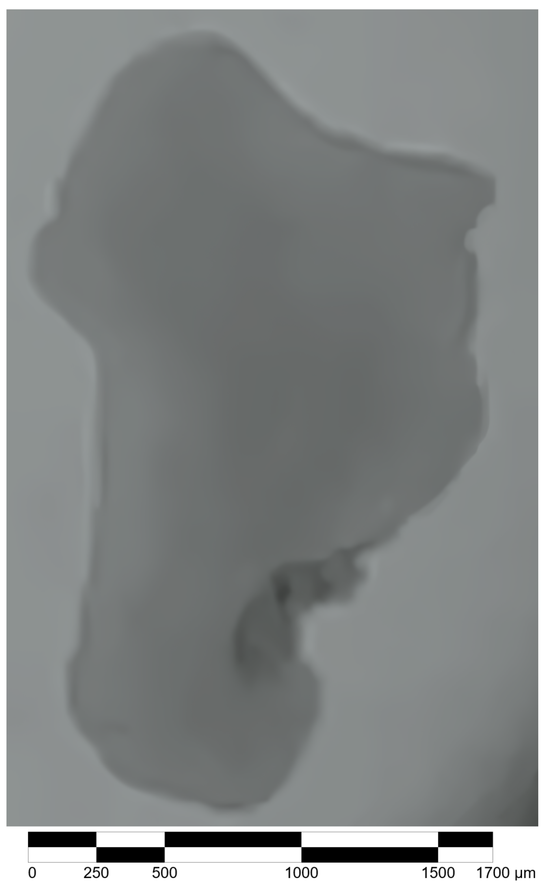
Trichoplax adhaerens provides a unique and exciting opportunity to explore the intricate relationship between gravity and life. Its simple genetic and morphological structure, simple cultivation in small life support systems, and distinct responses to changes in gravity make it an excellent model system for studying the effects of gravity on living organisms. For this purpose, a small microscope (the Trichoscope), described below, was developed to record the movement behavior of
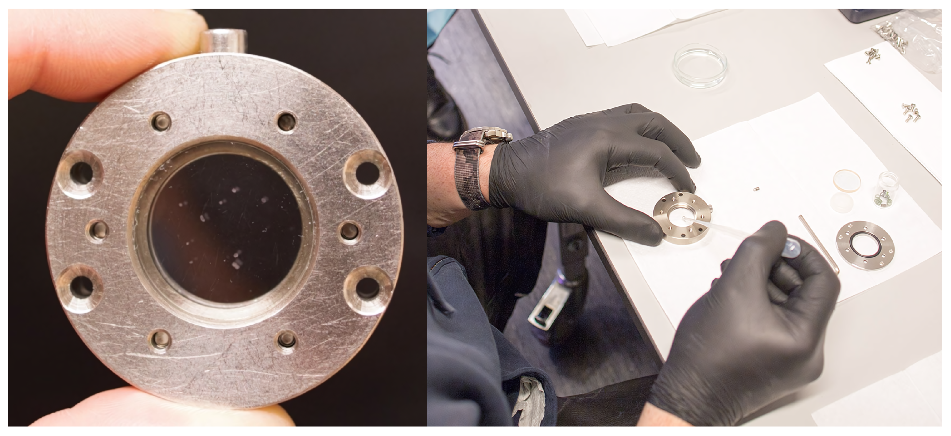
Trichoplax by means of video recording. In addition, these data were transmitted live to the Internet for the first time in the MAPHEUS project. The model organism was cultivated under standard conditions. Approximately 35 individuals were washed twice with sterile filtered artificial seawater and inserted into a stainless steel glass cuvette (see
Figure 6 and
Figure 7).
As with the first apex, Mk.2 and Mk.3’s main purpose for their flight was to flight-approve the overall systems, changes, and gather scientific data via the Trichoscope. The Trichoscope is an FDM-printed frame, holding an optical cell that was used to conduct behavioral studies under microgravity environments using the Mk.2 camera. Additionally, the Trichoscope was supplied with a TC-controllable LED for illumination and uses a heating foil, temperature sensor, and control circuit to keep the specimen under testing at a constant temperature. The same control circuit also logged the optical cell temperature for later analysis. The overall system was designed in that way so it could be operated toolless.
Due to the nature of the used rocket motor configuration, use of accelerometers was allowed; however, recording of said data was only agreed upon after start of microgravity. This phase was announced by a service module Signal (here Start of Data Storage (SoDS)), or could be sensed by accelerometers without recording. With the Mk.2 possessing its own accelerometer and gyroscope, their data was used to allow for offline microgravity environment sensing. The data acquired by the very conservative detection method could be compared with the real data and the method used in future apex systems to allow for higher independence of the service module or to free up signal lines.
Among the other experiments on Mk.2 was a thorough checkout of the TM/TC MCU, the Telemetry multiplexer, and their attached systems, e.g. the Mk.2 RPi, Mk.2 payload simulator, and the Mk.3—as well as tests of the hazardous commanding system. This was facilitated by commanding the subsystems from ground after launch mid-way to apogee, at apogee, and mid-way to landing again.
The utilized apex ground segment, based on open-source technology, securely connected the relevant experiment TM/TC data streams from the science network in Kiruna, Sweden, with virtualized servers in Cologne, Germany, where all data was processed and sent back to Kiruna for use. Using this method, we were able to test a secure remote commanding concept that simulated the experience of a scientist working remotely at a distance of over 2000 km from Cologne. To measure the mean time between the time a remote scientist issues a command and the time a response is received, 10 ping commands were issued during flight alongside other test commands. Remote video of the Trichoscope and the Swedish Space Corporation (SSC) Countdown Clock were also transmitted like the TM/TC data streams in a secure way.
Additionally, the Mk.2 RPi carried 34 MB of randomized test data with pre-computed SHA256 checksums to check for memory corruption after return.
