Article

Control Algorithm for an Inverter-Based Virtual Synchronous Generator with Adjustable Inertia

by
Christian A. Villada-Leon
1,
Johnny Posada Contreras
1,*,
Julio C. Rosas-Caro
2,*,
Rafael A. Núñez-Rodríguez
3,
Juan C. Valencia
1 and
Jesus E. Valdez-Resendiz
4,*
1
Programa de Ingeniería Eléctrica, Grupo de Investigación en Energía, GIEN, Facultad de Ingeniería, Universidad Autónoma de Occidente, Cali 760001, Colombia
2
Facultad de Ingeniería, Universidad Panamericana, Alvaro del Portillo 49, Zapopan 45010, Jalisco, Mexico
3
School Electronic Engineering, Unidades Tecnológicas de Santander, Bucaramanga 680005, Colombia
4
Tecnologico de Monterrey, Av. Eugenio Garza Sada 2501, Monterrey 64849, Nuevo Leon, Mexico
*
Authors to whom correspondence should be addressed.
Eng 2025, 6(9), 231; https://doi.org/10.3390/eng6090231
Submission received: 6 June 2025 / Revised: 12 August 2025 / Accepted: 1 September 2025 / Published: 5 September 2025

Abstract

This paper presents the design and implementation of a control algorithm for power converters in a microgrid, with the main objective of providing the flexibility to adjust the system inertia. The increasing integration of renewable energy sources in microgrids has driven the development of advanced control techniques to ensure stability and power quality. The proposed algorithm combines droop control, synchronverter dynamics, and virtual impedance to achieve a robust and efficient control strategy. Simulations were conducted to validate the algorithm’s performance, demonstrating its capability to maintain voltage within acceptable limits and improve the inertial response of the microgrid. The results contribute to the advancement of intelligent and resilient microgrid development, which is essential for the transition towards a more sustainable energy system.

1. Introduction

Synchronous machines have traditionally been essential for electrical power generation systems, particularly in hydroelectric power plants and other forms of energy generation. They not only transform mechanical energy into electrical energy but also maintain synchronization with the grid frequency, thereby assisting in the stability and quality of the power system [1,2,3]. The increasing integration of renewable energy sources through electronic power inverters introduces a new concern in the power generation system. Unlike synchronous machines, which inherently store energy in their rotating inertia, helping to preserve system stability, inverters decouple generation from the load by missing the inertia link, leading to frequency fluctuations larger than in the traditional system, which may compromise stability; microgrids are especially vulnerable to that effect [4,5].
Voltage and frequency fluctuations pose a challenge in power systems, particularly in microgrids, where there are usually no synchronous generators. Frequency regulation is essential to ensure system stability, as imbalances between generation and demand can negatively impact the operation of connected equipment and lead to system instability [6,7]. Likewise, voltage regulation is fundamental for protecting loads, preventing unwanted activation of protection devices, and avoiding potential blackouts. Addressing these issues requires advanced control strategies capable of mimicking the inertial response of traditional synchronous machines while leveraging the flexibility of power electronic inverters [8,9].
This challenge has been addressed from the control point of view; one approach that can be considered traditional is the so-called droop control, which adjusts active and reactive power based on frequency and voltage variations, respectively. One of the most recent contributions to this field is the proposal of virtual synchronous machines (VSMs), which are inverters equipped with a controller that attempts to emulate the behavior of traditional synchronous machines through power inverters and advanced control algorithms. By replicating the inertia and damping characteristics of synchronous generators through a controller, VSM-based approaches can significantly improve frequency and voltage stability, particularly in microgrid applications [10,11,12,13,14,15,16].
This article proposes and tests the design of a control strategy for an inverter to become a virtual synchronous machine (VSM). The primary objective is to achieve VSM operation with the capability to adjust inertia, thereby enhancing dynamic behavior and voltage regulation in a microgrid, while ensuring stable operation under varying conditions. While previous works have independently explored adaptive inertia strategies [17] and PLL-less synchronization techniques [18], the main contribution of this paper lies in the novel and synergistic integration of these concepts into a unified control framework. The key technical innovations presented are as follows:
  • A Holistic PLL-less Control Architecture: A comprehensive control structure is proposed that joins synchronverter dynamics with a virtual impedance-based self-synchronization mechanism, eliminating the need for a dedicated Phase-Locked Loop (PLL). This inherently improves the controller’s robustness and stability margin, particularly under weak grid conditions, where PLLs are a known source of instability [19].
  • Synergistic Integration of Dynamic Inertia: This demonstrates how an adjustable virtual inertia can be seamlessly incorporated into a PLL-less framework, allowing the system to dynamically modulate its inertial response to minimize frequency deviations (nadir/overshoot) and the Rate of Change of Frequency (RoCoF), without the stability constraints imposed by a traditional PLL.
  • Improved Stability Margin and Computational Efficiency: The proposed controller achieves a superior stability margin by eliminating the adverse dynamics of the PLL. Furthermore, the direct emulation of the synchronous machine equations, without the computational overhead of a complex PLL algorithm, offers a pathway towards a more efficient implementation on digital signal processors (DSPs).
Simulation results are provided to validate the effectiveness of the proposed approach. This work contributes to the development of more stable and resilient microgrids, facilitating the integration of renewable energy sources and supporting the transition toward a more sustainable energy system.

2. The System Under Study

The system analyzed in this study employs a common three-phase inverter topology connected to the electrical grid; however, the proposed operational algorithm is also applicable to other topologies. The system under study consists of a full-bridge three-phase inverter, which is usually synthesized with an IGBT six-pack. An LCL filter is used to connect the inverter to the grid or microgrid, as shown in Figure 1.
The objective is to derive an algorithm that allows the system in Figure 1 to operate as a traditional synchronous generator. The Virtual Synchronous Machine (VSM) operates based on a mathematical model that defines its dynamic response to grid conditions. The model incorporates key electromechanical principles, such as the swing and power balance equations that govern the exchange of active and reactive power. As proposed in [14], the VSM must mimic the following Equations (1)–(5).
J θ ¨ = T m T e D p θ ˙
T e = M f i f i , sin θ
e = θ ˙ M f i f sin θ
P = θ ˙ M f i f i , sin θ
Q = θ ˙ M f i f i , cos θ
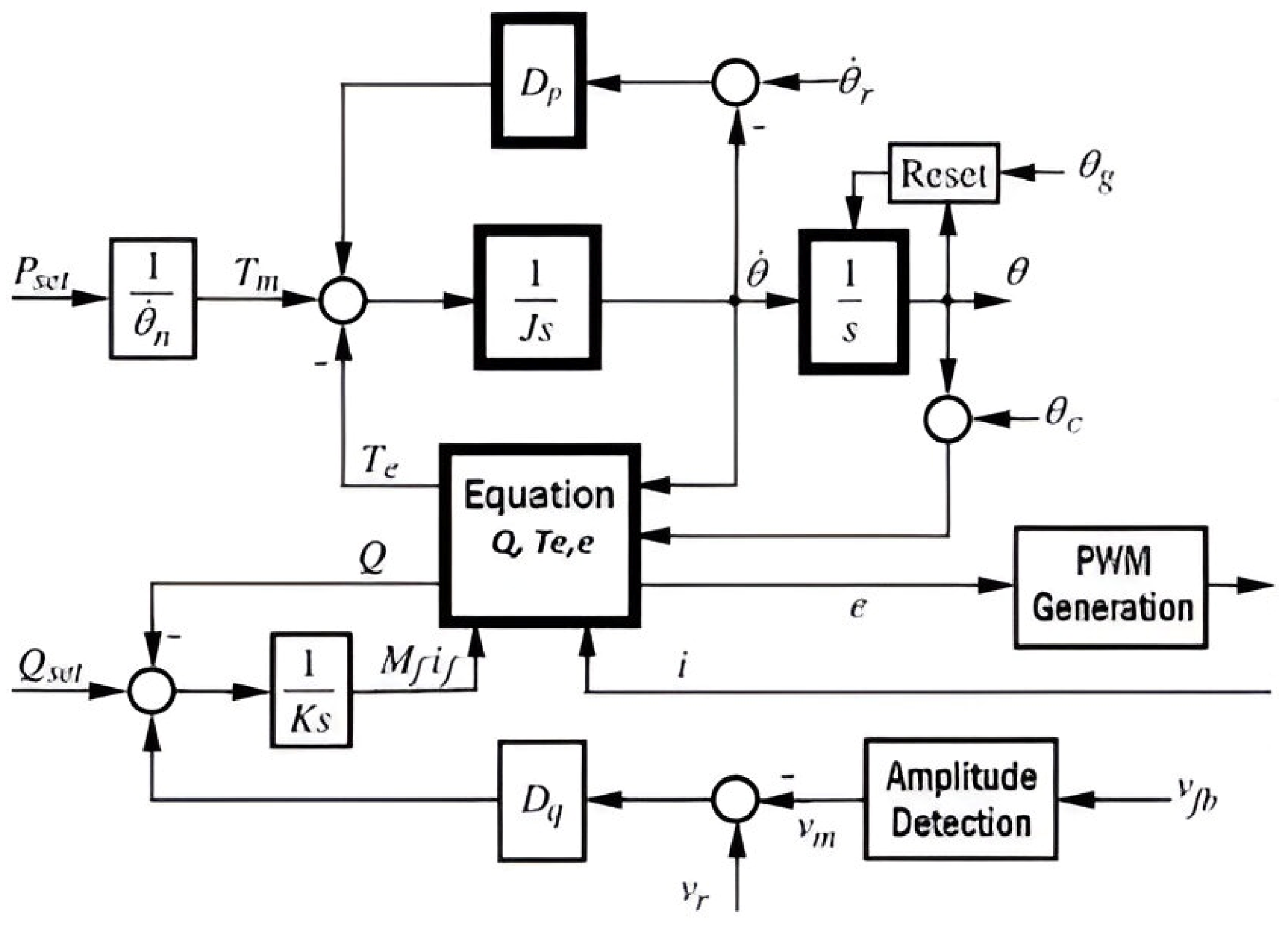
where Tm and Te are the mechanical torque applied to the rotor and the electromagnetic torque, respectively; e is the generated three-phase voltage, θ is the rotor angle, P and Q represent the active and reactive power, respectively, J is the moment of inertia of all rotating components in the system, and if is the field excitation current. Mf is the mutual inductance between the stator windings and the field windings, θ ˙ is the angular velocity of the machine, and Dp is the mechanical friction coefficient, which accounts for energy dissipation due to rotational losses. Figure 2 shows a block diagram of the system with the control described by (1)–(5).

3. Previous Works on VSM Derivations

The concept of Virtual Synchronous Machines (VSMs) has gained significant attention in recent years as a promising approach for improving the stability and reliability of modern power grids. Numerous studies have focused on developing and refining VSM control strategies to enhance grid inertia, frequency regulation, and voltage support.
Researchers have explored different implementations, including droop-based control, synchronverter models, and hybrid approaches. Given its potential to bridge the gap between traditional synchronous generators and power electronics-based systems, the development of VSMs remains an active area of research.
Table 1 presents a comparative evaluation of recent research studies focused on improving inertia in microgrids through strategies based on Virtual Synchronous Generators (VSGs) [20,21,22,23,24,25,26,27,28,29,30,31,32,33,34,35,36,37,38,39]. The studies are analyzed based on a set of positive and negative criteria, including mitigation of overshoot, reduction in the ROCOF, voltage and frequency regulation, and computational cost, among others. Each paper was assigned a score according to its strengths (P+), limitations (P−), and a total score (T) reflecting its overall effectiveness in enhancing inertia in microgrid environments.
The literature review indicates that most existing studies focus on islanded microgrid scenarios and tend to address frequency or voltage regulation issues separately, highlighting a research gap: the need for integrated control strategies that simultaneously address voltage regulation and inertial support. The three highest-scoring strategies—droop control, synchronverter, and virtual impedance control—serve as the foundation for the algorithm proposed in this work.

4. The Derived Algorithm

Considering the synchronverter model as an emulation of a conventional synchronous machine, its mathematical representation is developed by analyzing three main parts.
The internal electromechanical part is given by the dynamics of currents and fluxes in both the stator and rotor.
i a + i b + i c = 0
Φ = L s i + M f i f cos θ
Φ f = L f i f + M f i f , cos θ
The mechanical part is given as:
J θ ¨ = T m T e D p θ
T e = M f i f i f , cos θ
The external electrical can be written in any of the following equations:
V = R s i d Φ d t
V = R s i L s d i d t + e
Deriving the flux in (7) yields the following:
e = M f i f θ ˙ sin θ
The acceleration of the synchronous generator can be expressed as follows:
θ ¨ = 1 J T m T e D p θ ˙
To represent the mechanical equation of the synchronous generator using a block diagram, the Laplace transform is applied to Equation (14) and solved for the angular velocity as follows:
θ ˙ = 1 J s T m T e D p θ ˙
To obtain the rotor angle θ, it is sufficient to integrate the angular velocity (its derivative). Figure 3 illustrates the block diagram representation of the synchronous generator’s mechanical equation.

4.1. Droop Control for Frequency and Active Power

In a synchronous generator with frequency regulation, the active power regulation system must ensure that torque equilibrium is maintained by adjusting the mechanical torque appropriately and then deliver the active power to the grid based on the grid frequency. This action is carried out through a control loop known as frequency droop control.
According to [14], the frequency droop mechanism can be implemented in a synchronverter by comparing the virtual angular velocity with a reference, which can be equal to the nominal grid angular frequency. The difference between these values, multiplied by a gain, is added to the mechanical torque Tm. The equations show that the effect of the droop control loop is equivalent to a significant increase in the mechanical friction coefficient Dp. Thus, the constant Dp now represents the sum of the imaginary mechanical friction coefficient and the frequency droop coefficient. Therefore, denoting the change in total torque acting on the imaginary rotor as ΔT and the change in angular frequency as Δ θ ˙ , and considering typical values of frequency droop—where a 100% increase in power corresponds to a frequency drop of 3% to 5% from the nominal values—the following relationship holds the following:
D p = Δ T Δ θ ˙
The mechanical torque Tm can be obtained by dividing the reference active power Pset by the nominal mechanical speed. For example, if we use the 60 Hz grid frequency, the angular velocity is 377 rad/s, and the power is P = 5000 W, and we consider a 5% frequency variation relative to the maximum torque.
D p = 5000 377 0.05 × 377 = 0.703
The advantage of the synchronverter is that the moment of inertia J can be chosen to suit specific requirements to have a desired time constant of the frequency drop control loop; for example, if we want the time constant to be one-tenth of the frequency (1/600 = 1.6 mS). J = DpTf = 0.00117.

4.2. Droop Control for Voltage and Reactive Power

To implement the reactive power regulation system, the voltage control loop of e is first implemented using an integral control with a constant 1/Kq to generate Mf if. Recalling the expression for the electromotive force in the synchronverter, given by (3), the constant Kq can be chosen as 377 to cancel the angular velocity.
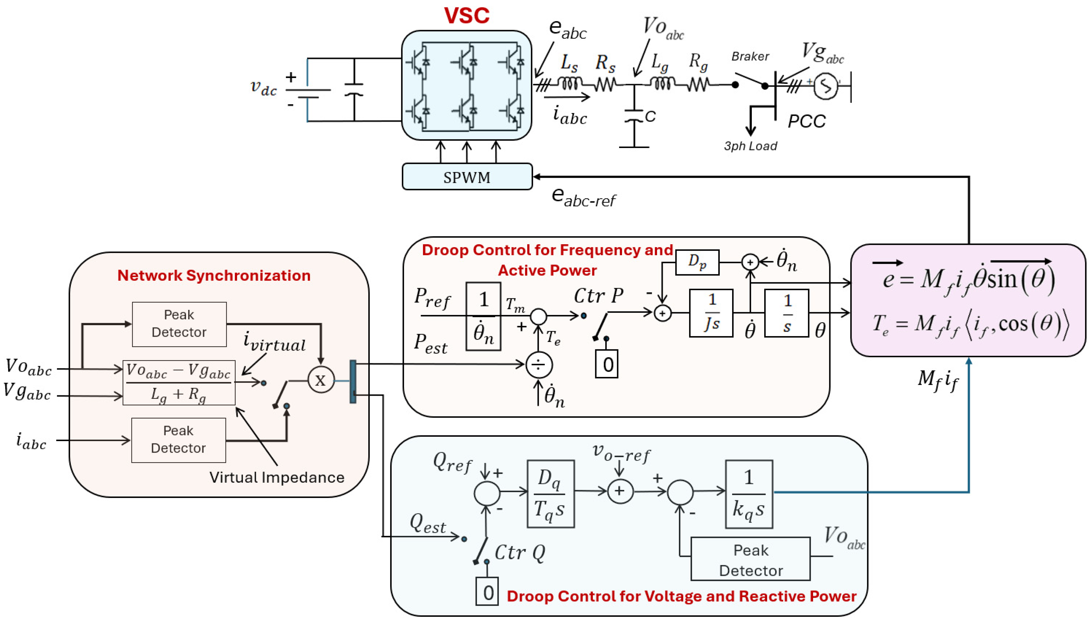
The next step in voltage droop control is the implementation of the reactive power regulation system, for which a control scheme, as shown in Figure 4, is proposed. The difference between the desired reactive power and the reactive power delivered by the synchronverter represents the reactive power tracking error. This error is multiplied by the voltage droop coefficient Dq and then fed into an integrator with a time constant, Tq. The output of the integrator serves as the voltage reference for the synchronverter, ensuring appropriate reactive power compensation and stable operation.

4.3. Control Loop for Grid Synchronization

For the inverter to operate as a synchronous generator, it must be synchronized with the grid before connection. Synchronization requires matching the frequency, voltage magnitude, phase, and phase sequence of the synchronverter with those of the grid. When these conditions are met and the connection is just established, there is no exchange of active or reactive power between the synchronverter and the grid.
Most grid-connected three-phase converters use a dedicated synchronization unit. The most well-known synchronization method is the Phase-Locked Loop (PLL), which provides the amplitude, frequency, and phase of the grid voltage.
In [14], a radical approach is proposed to enhance the synchronverter by transforming it into a self-synchronized synchronverter through the elimination of the synchronization unit, enabling the synchronverter to automatically synchronize with the grid before connection without the need for an external PLL. To achieve automatic synchronization, the proposed method incorporates an additional control block in the synchronverter, which is responsible for emulating the current flowing through the grid inductors Lg without requiring a direct connection to the grid (virtual impedance). The control block responsible for emulating the current through the grid inductors Lg is derived using the following expression:
i v i r t u a l = V o a b c V g a b c L g + R g
A Ctrl switch is implemented to introduce the virtual current into the synchronverter equations during the synchronization phase while allowing the actual current measured by the power electronics sensors to be used during normal operation. The inclusion of virtual impedance loops and damping algorithms minimizes transient currents at the instant of connection to the grid, as shown in recent works [40,41].
By utilizing a virtual current and setting the active and reactive power references to zero, synchronization can be achieved.
There is a natural delay in the system, which causes a difference between the reference voltage Vgabc and the voltage synthesized by the converter Voabc. Consequently, a discrepancy also exists between the estimated power and the measured power at the connection terminals. To compensate for this, a power meter has been included at the terminals to provide feedback to the system.
Feedback is obtained through Te for the active power control loop. By referring to the synchronous generator equations for electrical torque, Te is equal to the active power divided by the angular speed or can be found using (10).
Figure 4 illustrates the complete control diagram for the three-phase inverter, which incorporates both voltage and frequency droop control, as well as the system synchronization mechanism. Table 2 lists the parameters and definitions used in the control system.
Additionally, to guarantee the proper operation of the inverter, the DC bus voltage must be maintained at a level higher than the peak phase voltage of the AC source:
V D C min > 6 V p h a s e
For a phase voltage of 120 V, a DC voltage larger than 294 V is required; therefore, considering (16), a 500 V DC bus was selected to ensure an adequate voltage margin.
From Figure 4, the calculation of the virtual current is observable. This current is obtained from the potential difference between the generated voltage and the grid voltage. When this difference is passed through a virtual impedance, it is converted into a virtual current, which is then used to compute the power values and, subsequently, the torque required for the synchronization process. The virtual impedance includes both inductive and resistive components, as the connection between the grid and the load is inherently inductive.
To bring the synchronverter system online, synchronization must first be performed as follows:
(a)
The Ctr P and Ctr Q switches are initially set to use “0” as the reference. This configuration enables the Voltage Source Converter (VSC) to generate an output voltage, Vo, at a reference frequency (θn) and a reference magnitude (Vo-ref).
(b)
Subsequently, the switches are commutated to use Pest and Qest as the new references. This step is critical, as it utilizes the virtual impedance to synchronize the VSC’s frequency and voltage with the grid prior to connection, ensuring that the transient upon connection is minimal. The quality of the synchronization will depend on how accurately the values of Lg and Rg are determined in the real implementation.
(c)
During the synchronization process, the synchronization network must have the reference current iVirtual selected. The inverter’s connection to the grid is only established when the value of iVirtual approaches zero.
(d)
Once the VSC inverter is connected to the grid, the synchronization network’s switch selects the actual current being delivered by the inverter. This current, which should be very close to zero at the moment of connection, is then used to calculate the active and reactive power that the VSC supplies to the point of common coupling (PCC). At this stage, the power references, Pref and Qref, are set by the user or by another grid control algorithm.

5. Simulation Results

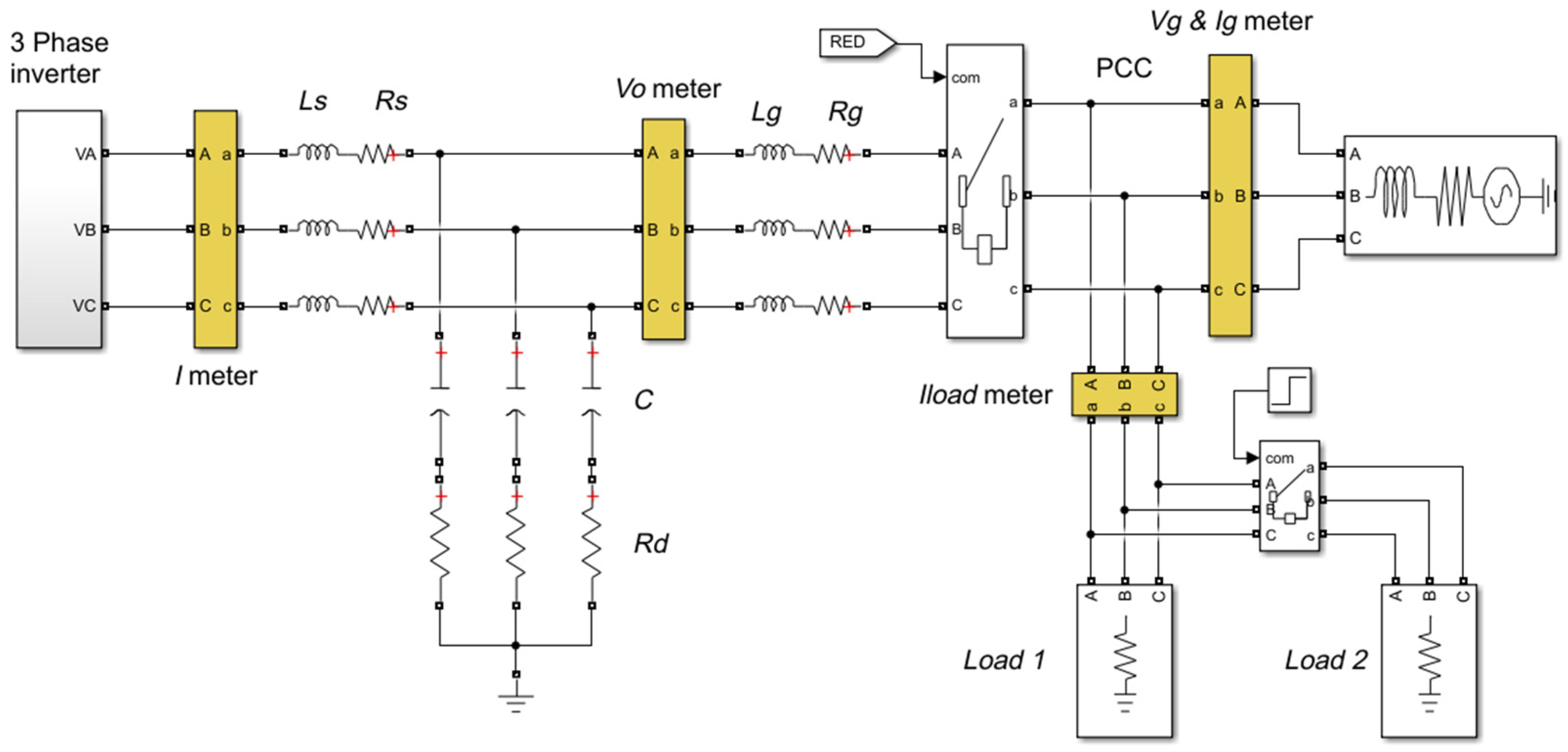
To validate the performance of the proposed control algorithm, simulations were carried out using MATLAB/Simulink R2020a. A simulation of a three-phase inverter operating as a synchronous generator under dynamic conditions was developed, as shown in Figure 5. The modeled system consists of a three-phase inverter with a 500 V DC bus, an LCL filter specifically designed to attenuate switching harmonics, and a three-phase power grid with 220 V (line-to-line) at 60 Hz. The control structure integrates droop control loops for both frequency and voltage, as well as an automatic synchronization mechanism based on virtual impedance.
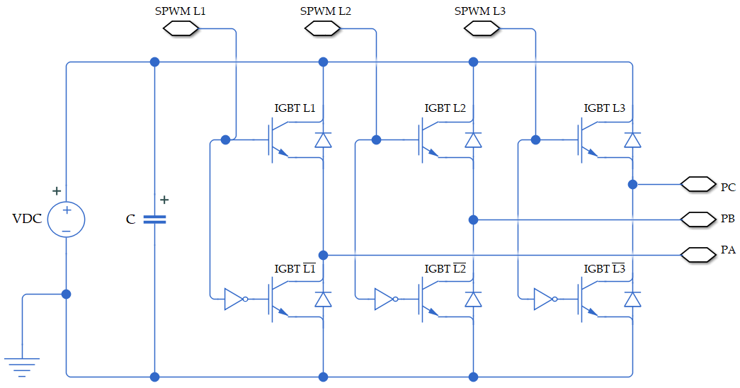
The inverter is implemented using a three-phase H-bridge with six IGBT transistors (Figure 6), controlled by a sinusoidal pulse-width modulation (SPWM) signal. The inverter’s output voltage is directly connected to the LCL filter, which consists of two symmetrical inductors, a central capacitor, and a damping resistor that enhances the system’s response to resonances. This filter ensures that the output signal complies with power quality standards.
The control system is based on a synchronverter model that integrates two droop-type control loops: one for frequency and active power regulation and another for voltage and reactive power regulation. The frequency controller adjusts the virtual mechanical torque Tm by comparing the virtual angular frequency with the reference frequency. On the other hand, the voltage controller generates the virtual field excitation Mfif based on the required reactive power, which allows the voltage profile to be maintained under both steady-state and transient conditions.
Additionally, a grid synchronization mechanism based on the estimation of a virtual current is incorporated. This current is calculated as the difference between the inverter-generated voltage and the grid voltage, divided by a virtual impedance consisting of resistive and inductive elements. From this estimated current, the active and reactive power are calculated. Along with zero reference values, this enables the inverter to synchronize with the grid without the need for a phase-locked loop (PLL). Grid connection occurs automatically once the voltage, phase, and frequency conditions are matched.
To evaluate the behavior of the inverter operating in synchronous generator mode, it is necessary to apply signals in sequence so that the controllers activate in the correct order; for this, the Simulink Signal Builder block is used. During the simulation, the control blocks are activated sequentially: frequency droop starts at t = 0.5 s, followed by voltage droop at t = 1.0 s, and grid connection at t = 1.5 s. Subsequently, controlled disturbances are introduced in the active and reactive power references, as well as load changes, to evaluate the system’s robustness and response capability. This simulation establishes the initial conditions required for result analysis, demonstrating the proposed system’s stability, accuracy, and speed under dynamic operating conditions.
Once the three-phase inverter model was implemented as a virtual synchronous machine, various tests were conducted to evaluate the system’s dynamic performance under load disturbances and changes in active and reactive power references. The simulation demonstrates that the developed control strategy enables stable operation, rapid response, and compliance with the NTC 1340 [42] and IEEE 1547-2018 [43] standard (58.8–61.2 Hz). Voltage variations remain within the limits defined by the ITIC curve, ensuring compliance with power quality standards in distribution systems.

5.1. Frequency Response

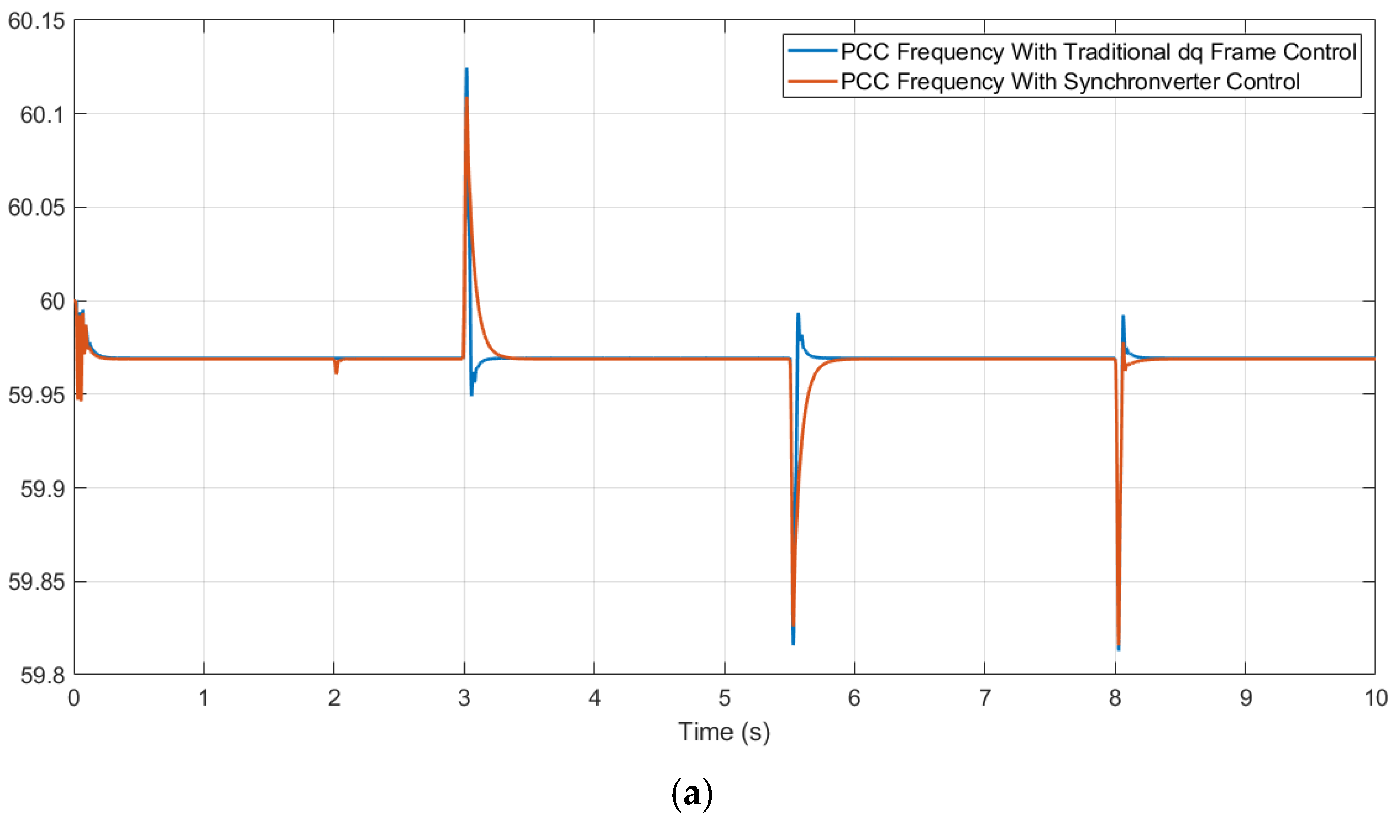
Figure 7a shows the evolution of the frequency at the PCC node under various events, comparing the frequency response of a power control algorithm in the dq reference frame with that of the synchronverter control algorithm presented in this paper. The system is initially stable at approximately 59.96 Hz with a 3 kW demand. The power converter connects to the PCC at t = 2 s, where a minor frequency variation—caused by the virtual impedance effect and slight mismatches with the actual grid impedance (Lg and Rg)—is quickly compensated.
Exploring Figure 7a,b, at t = 3.0 s, a 3000 W active power reference is introduced, causing a slight deviation to 60.12 Hz and 60.11 Hz for the traditional dq-frame control and the synchronverter control, respectively, with the system stabilizing within 296 ms. When the power injection ends at t = 5.5 s, the frequency temporarily drops to 59.82 Hz and 59.83 Hz, stabilizing again within 349 ms. At t = 8.0 s, an additional 2 kW load is connected, resulting in a controlled frequency drop to 59.81 Hz and 59.82 Hz, with full recovery occurring in 150 ms. In all cases, the system remains within the limits established by the NTC 1340 and IEEE 1547-2018 standard, demonstrating an effective inertial response.
As a primary observation, the response times of both control strategies are similar; however, the synchronverter technique exhibits a more damped response compared to the synchronous dq-frame control. Although the stabilization time is not substantially improved, a clear enhancement is observed in the reduction in frequency deviations and in the overall frequency transient.

5.2. Active Power Transfer

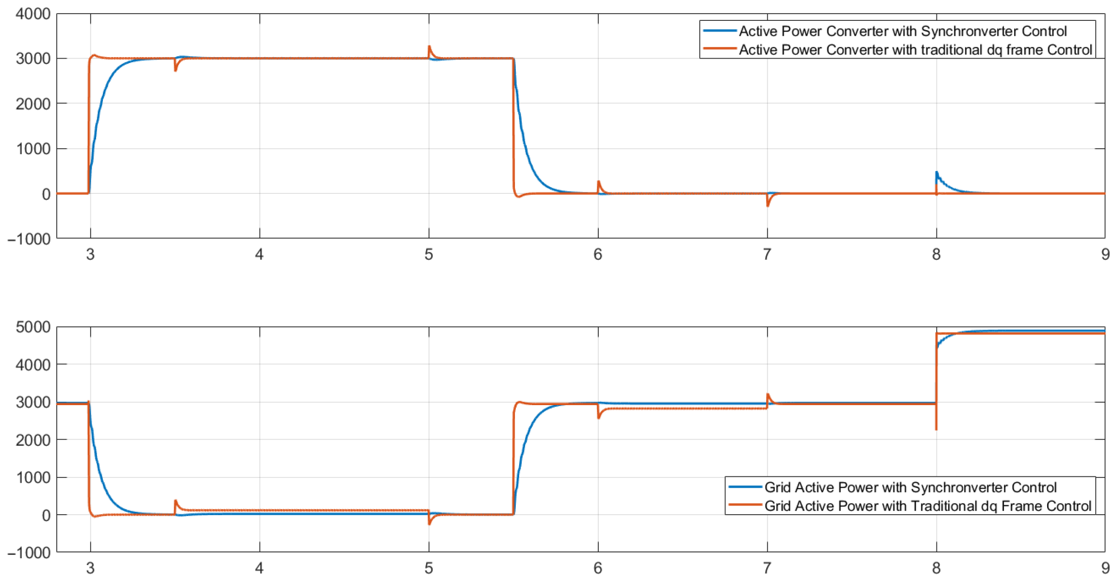
The active power behavior shows proper coordination between the inverter and the grid, as illustrated in Figure 8. At t = 3.0 s, the inverter starts injecting 3000 W, supplying 100% of the active load while the grid reduces its contribution to zero. At t = 5.5 s, the reference returns to zero, and the grid resumes supplying the load. At t = 8.0 s, as the load increases to 5000 W, the grid responds immediately, and the inverter attempts to stabilize its contribution, demonstrating effective load sharing and reference tracking.

5.3. Voltage Regulation

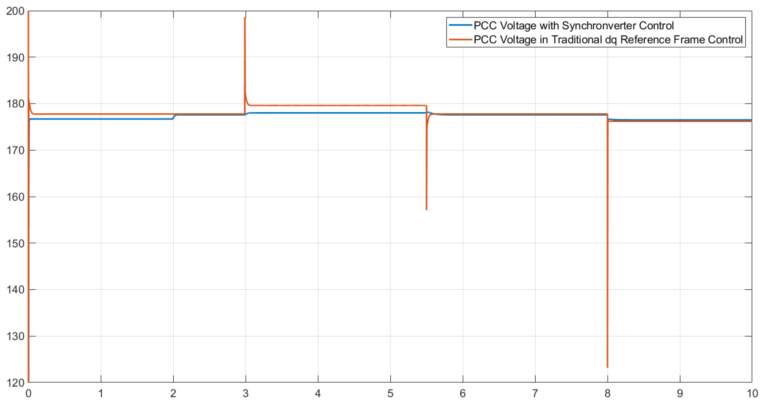
The inverter’s output voltage remains stable around 179 V peak (127 Vrms), even during transient reactive power events. Small amplitude variations are observed, as shown in Figure 9, all within the limits defined by the ITIC curve, ensuring adequate power quality for sensitive connected loads.

5.4. Synchronization Without PLL

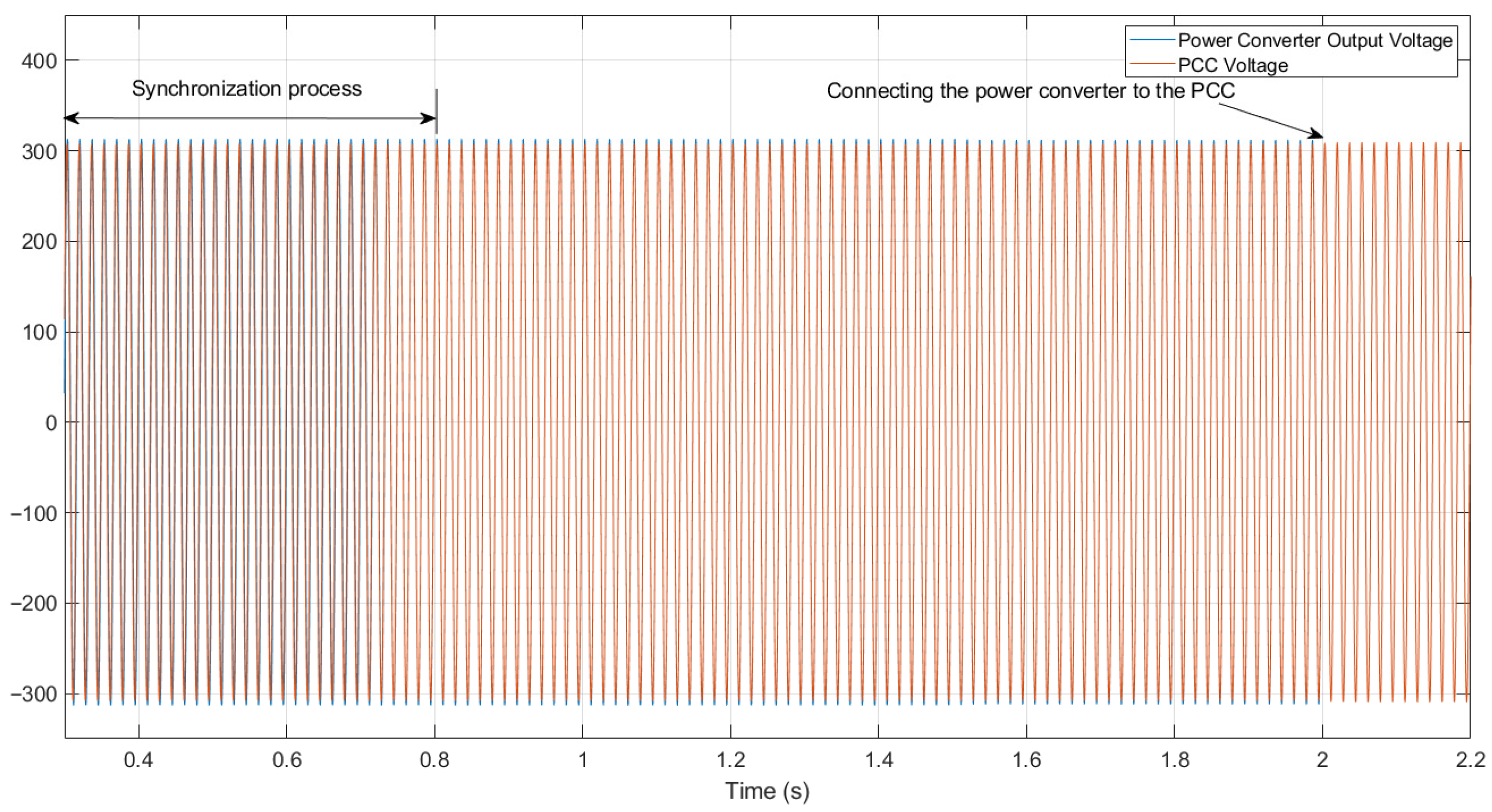
One of the most significant achievements of the simulation is the ability to synchronize automatically without the use of a phase-locked loop (PLL), as shown in Figure 10. Thanks to the use of a virtual current estimated through a virtual impedance, the inverter can match its frequency, amplitude, and phase with the grid before connection. This synchronization is completed within the first 1.5 s of the simulation, and the connection is established without abrupt power transfer.
In Figure 10, the inverter and grid voltages are shown at the beginning of the virtual machine operation, with a clear phase and amplitude mismatch. Both voltages are matched in amplitude, phase, and frequency at 2 s, the moment when the connection occurs. Additionally, no variations are observed in either voltage, confirming that the controller is operating properly.

5.5. Simulation of DC/AC Converter Under Weak Grid Conditions and Frequency Variation

To test the grid synchronization and frequency stabilization functionality in a weak grid scenario, the supply system from previous simulations is slightly modified. For this new scenario, the main source is modeled as a synchronous generator with limited power capacity, making it sensitive to load disturbances. The simulation used the following parameters for the main source: 10.2 kVA, 1800 RPM, 220 Vac, and 60 Hz.
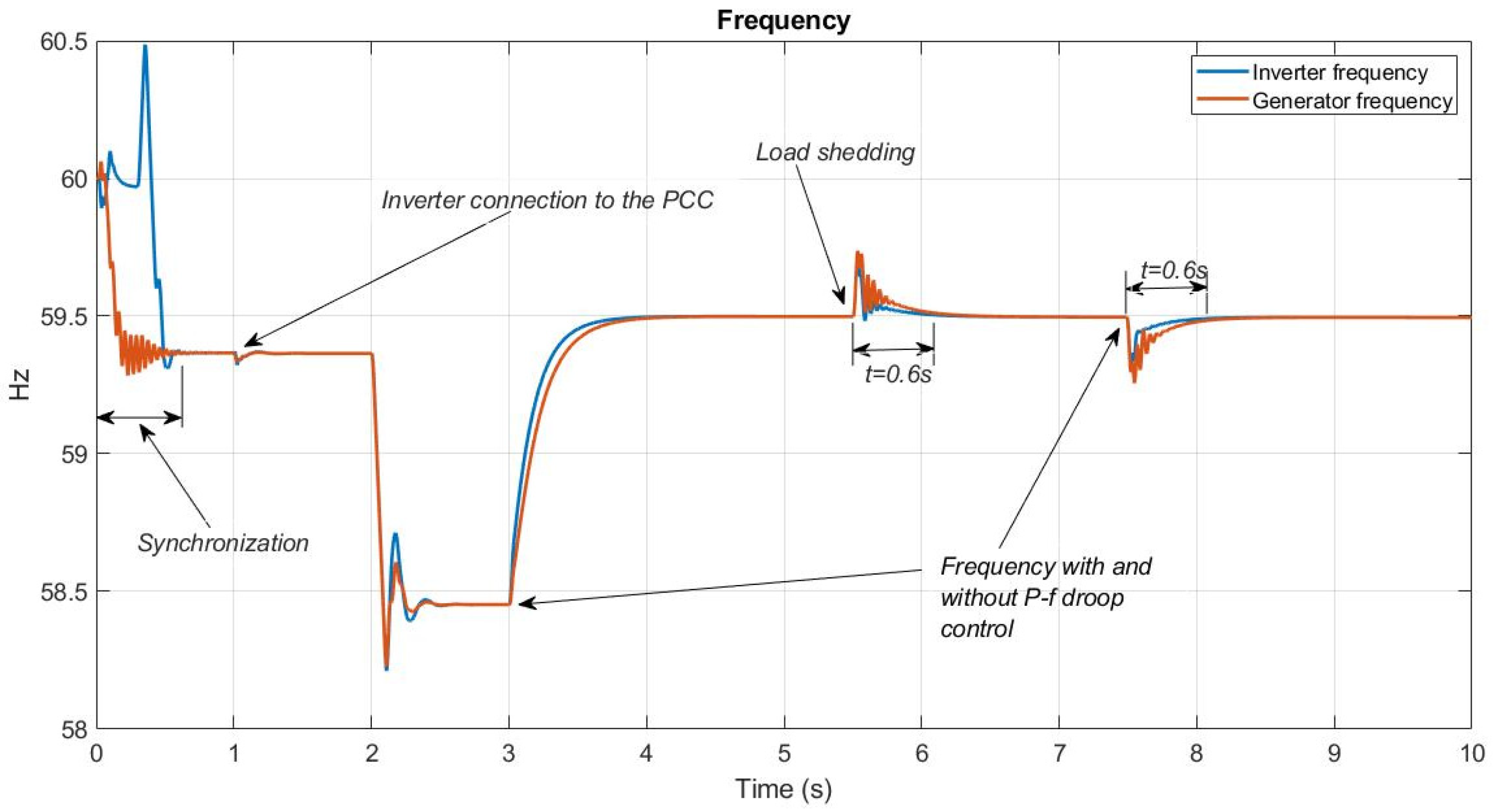
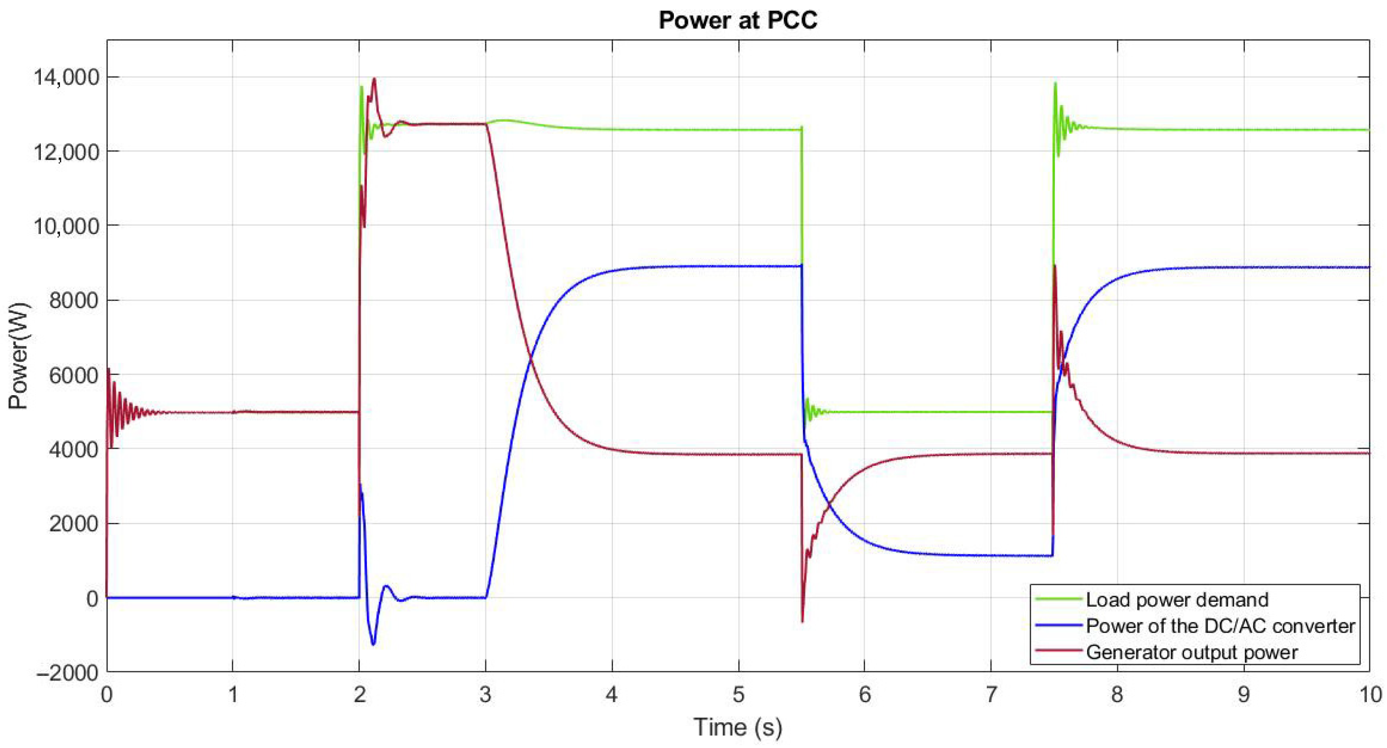
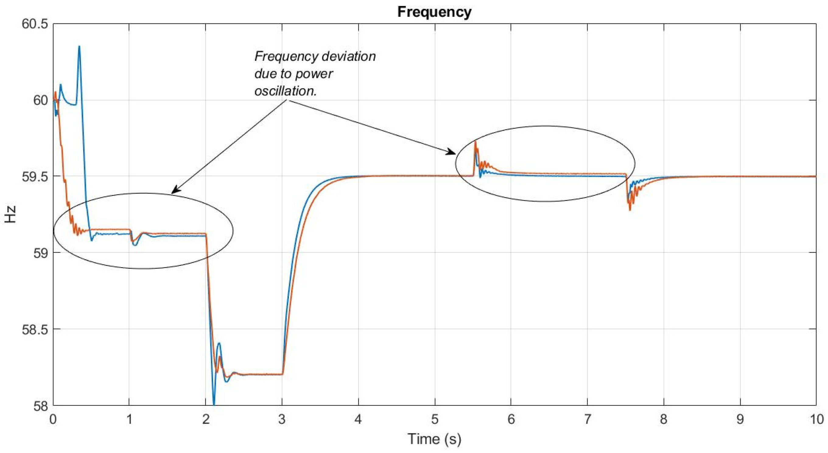
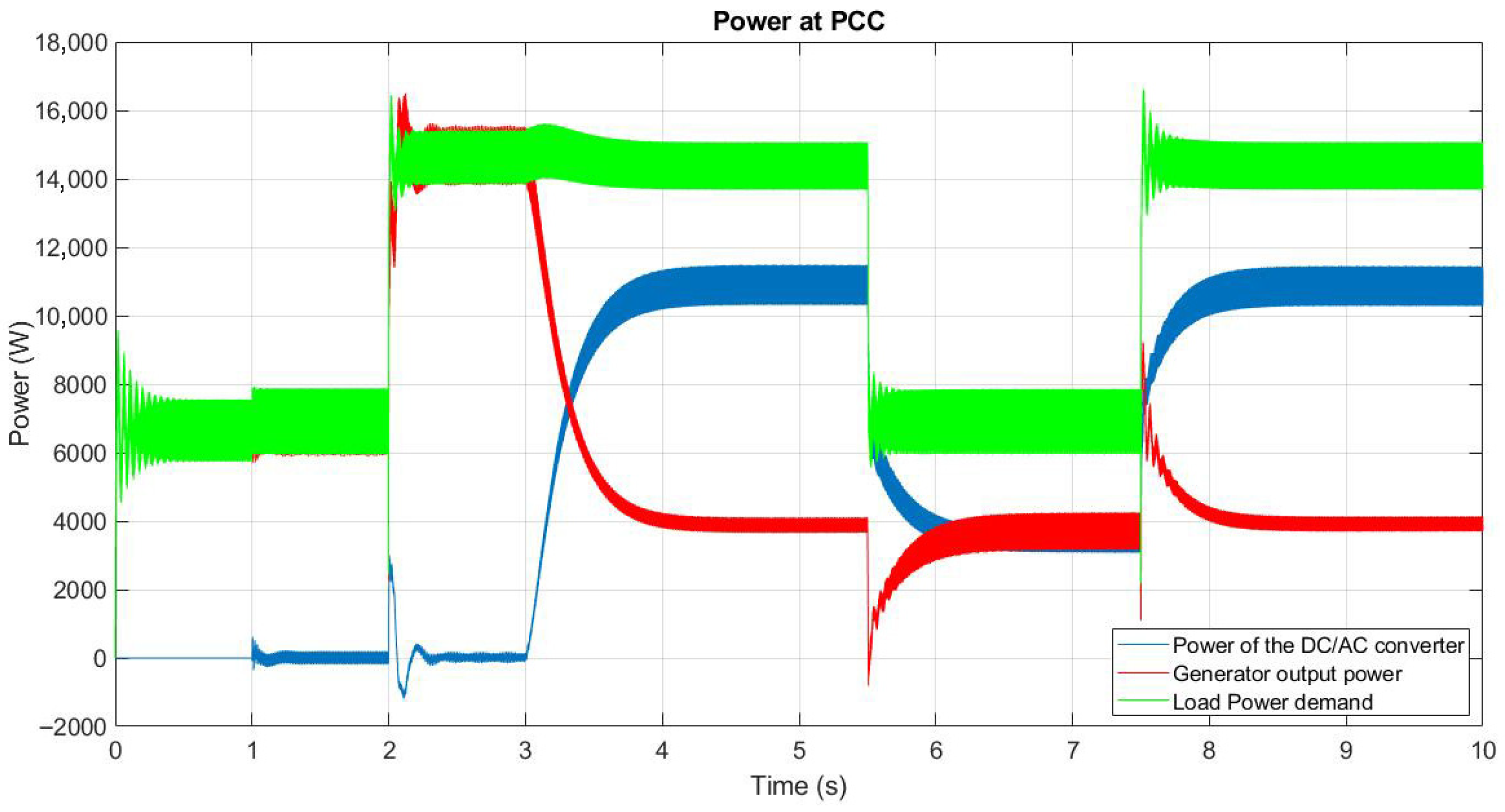
The test begins with a 5 kW load connected to the PCC. At t = 1.0 s, the synchronverter is connected to the electrical grid but does not supply power to the PCC, establishing the grid frequency at 59.36 Hz, which is within the continuous operating range specified by IEEE 1547-2018. At t = 2.0 s, an 8 kW load is connected to the PCC, causing the generator’s power output to increase and the grid frequency to drop to 58.45 Hz. At t = 3 s, the DC/AC converter is commanded to inject power into the grid. The amount of injected power is determined by the DC/AC converter’s droop control, which aims to re-establish the grid frequency within the permissible limits of 58.8 Hz and 61.2 Hz, eventually settling at 59.5 Hz. At t = 5.5 s, the sudden load is removed, returning the grid to its initial 5 kW load, with the key difference that the grid frequency is maintained at approximately 59.5 Hz. At t = 7.5 s, the 8 kW load is reconnected, causing a small frequency transient that remains within the permissible range of the standard. In the sudden load events at t = 2 s and t = 7.5 s, the effect of the synchronverter-driven droop control on the grid frequency is observed. Operation and synchronization times are illustrated in Figure 11, Figure 12 and Figure 13. The aforementioned events are detailed below:
  • Grid synchronization of the DC/AC converter occurs at t = 0.4 s, and its connection to the grid is executed at t = 1 s. The connection is performed manually (Figure 11). This connection step can be automated, a task planned for future experiments.
  • A sudden load at the PCC at t = 2 s exceeds the generator’s nominal capacity (Figure 12—green line), forcing the frequency to drop below the 58.8 Hz limit established by the IEEE 1547-2018 standard. Figure 12 shows this frequency drop, and Figure 13 shows the increase in power delivered by the generation to the PCC, reaching approximately 13 kW (red line).
  • The DC/AC converter with the synchronverter begins operation to restore the frequency to normal ranges. Here, the power contribution from each generation source is 8.9 kW from the DC/AC converter (Figure 13—blue line) and 3.86 kW from the generator connected to the PCC (Figure 13—red line). This corresponds to a slight drop in the load’s power, attributed to voltage regulation. Figure 12 shows the restoration of the PCC frequency to permissible operating levels (f = 59.5 Hz).
  • Sudden load shedding occurs at t = 5.5 s to verify the frequency behavior and power sharing while the DC/AC converter is injecting power into the grid, prioritizing frequency regulation. The frequency remains constant after a short operating transient, which lasts 0.5 s and causes a frequency increase of 0.24 Hz without exceeding permissible limits (see Figure 12).
  • The previously described sudden load event is repeated at 7.5 s, identical to the load applied at 2.5 s. This time, the test is performed with the synchronverter’s power droop control active in the DC/AC converter. This event is executed to verify the droop control’s operation in the converter, acting as an inertia compensator with a correction time of 0.6 s.

5.6. Simulation of DC/AC Converter Under Weak Grid Conditions and Non-Linear Load

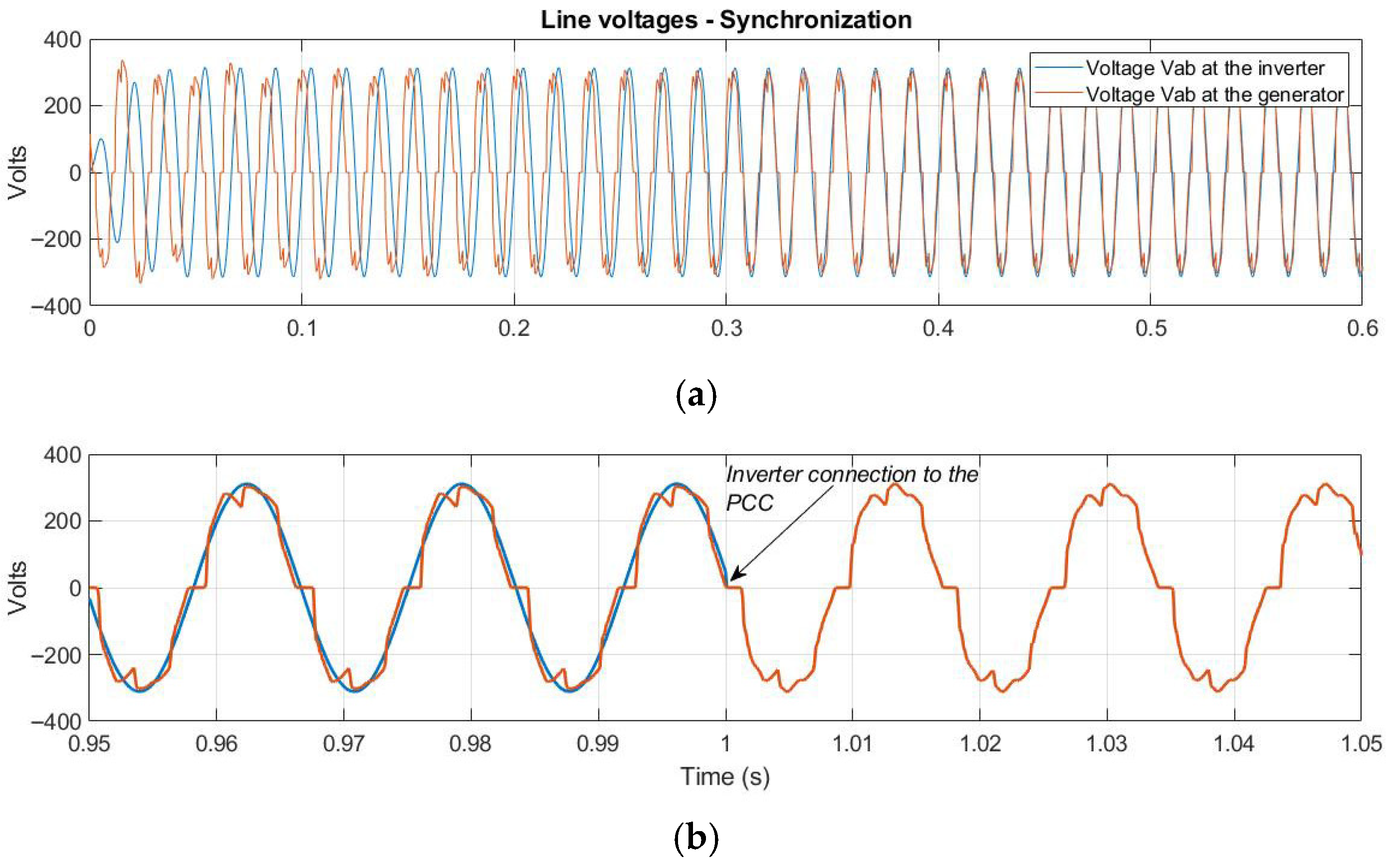
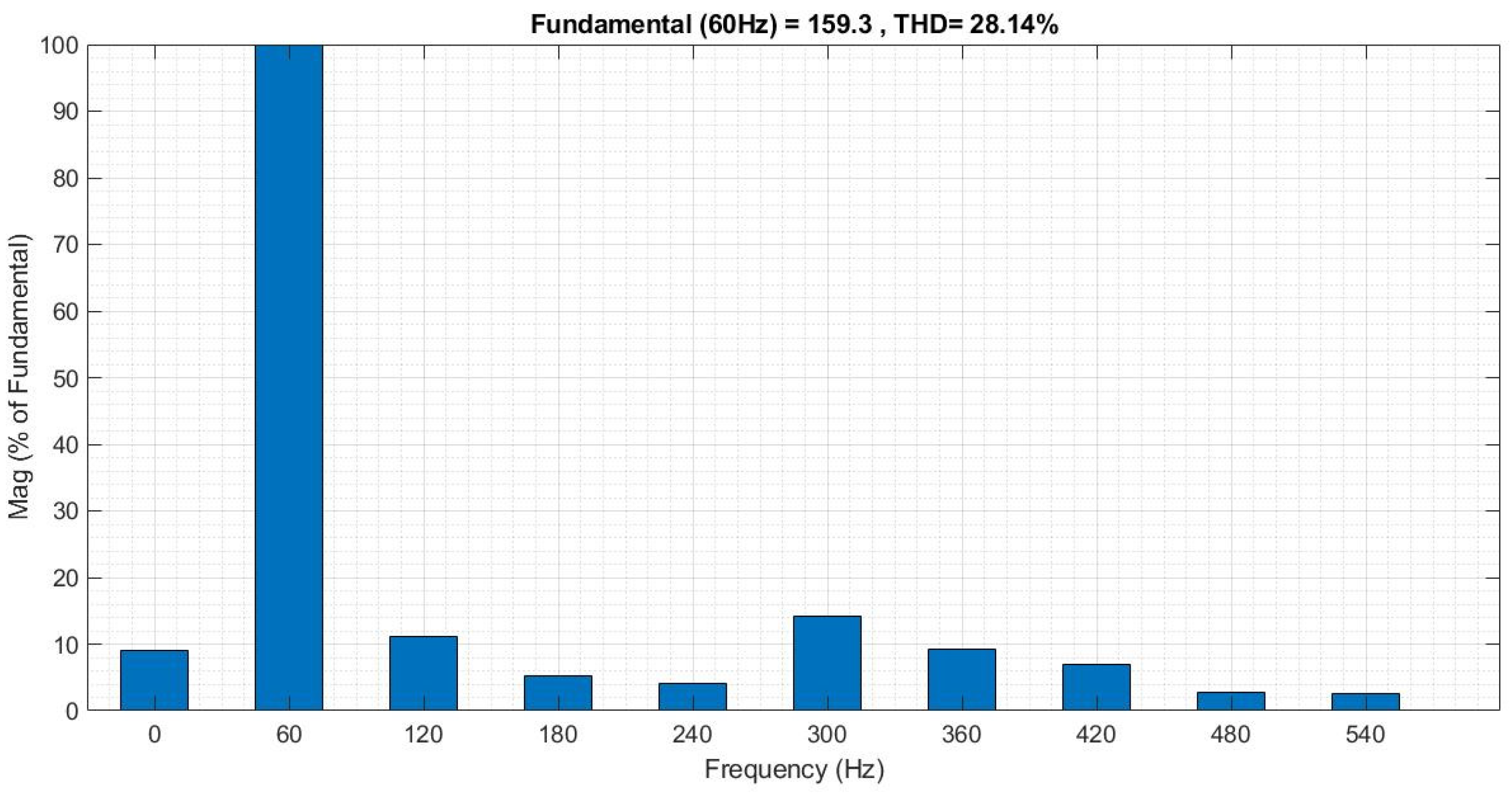
To test the DC/AC converter system with the synchronverter under non-linear load conditions, the system is evaluated with a THDv of 28.14%. The load is divided into a 2 kW active component and an approximately 5 kW non-linear load, which are kept fixed throughout the test. Additionally, an 8 kW linear load is connected to and disconnected from the PCC, producing an overload at the node and frequency deviation, resulting in a total approximate load power of approximately 15 kW. The voltage waveforms at the PCC node are shown in Figure 14, and their harmonic components are depicted in Figure 15.
The timing for the transient events is kept the same as that used in Section 5.6 to directly compare the events with a linear load versus a linear + non-linear load. A description of the simulation events follows:
  • Figure 14a shows the synchronization process of the DC/AC inverter’s waveform with the PCC signal, which contains harmonic content; synchronization is achieved at t = 0.4 s. Figure 14b shows the instant the inverter is connected to the PCC node, where the dominance of the node’s voltage is observed. Figure 15 displays the harmonic content of the voltage signal, which causes oscillations in the power exchanged between the converter and the grid and between the grid and the load. Despite the voltage’s harmonic content, synchronization is possible because the virtual impedance used in this process is equivalent to the coupling impedance (comprising Lg and Rg), which is small, thereby minimizing the power oscillations generated by voltage harmonics during synchronization. As a next step, the THD limit at which synchronization is no longer possible should be established, and the level of interaction and coupling between the power oscillations and the control loops must also be determined, as these topics are subjects for investigation and presentation in future work.
  • A sudden load at the PCC exceeds the generator’s nominal capacity, causing the frequency to drop below the 58.8 Hz limit, as shown in Figure 16. In this case, the frequency drop is slightly larger due to the power difference compared to the previous test, as shown in Figure 17.
All subsequent events remain the same as in the test performed in Section 5.5: the start of operation of the DC/AC converter with the synchronverter to restore the frequency to normal ranges, the load shedding to verify frequency behavior and power contribution to the grid from the converter, and the load reconnection to verify the converter’s operation as an inertia compensator.
Since the synchronverter control algorithm uses power measurement for frequency compensation, the presence of harmonics causes sustained power oscillations that will affect the synchronverter’s performance. Papers such as [44,45,46] present studies and potential solutions for the interaction of control loops and grid impedances, which generate oscillations that compromise the stability of the synchronverter.

6. Conclusions

This work presented the design and simulation-based validation of a controller grounded in the concept of a virtual synchronous machine (synchronverter), complemented with droop strategies for frequency and voltage regulation in microgrids. The results demonstrate that the proposed system effectively emulates the inertial behavior of synchronous generators, enabling stable active power transfer and reactive power compensation, even under dynamic load disturbances. The inclusion of a damping resistor in the LCL filter proved essential for improving the transient response of active power. Additionally, the implementation of automatic synchronization without a PLL, using estimated virtual current, reduced system complexity and ensured a safe connection to the grid.
Moreover, the study identified relevant effects of line impedance on voltage control and emphasized the importance of proper phase synchronization to avoid connection errors. The proposed architecture proved to be efficient, computationally lightweight, and suitable for real-world implementation in power converters. While the MATLAB/Simulink results presented in this article validate the fundamental performance of the proposed control algorithm, it is recognized that real-world implementation presents additional challenges, such as computational delays, sensor noise, non-linear loads, and hardware non-linearities. To bridge the gap between simulation and physical deployment, an experimental validation plan is contemplated as the next phase of this research.
The immediate next step will involve validation using Power Hardware-in-the-Loop (PHIL). This methodology enables testing the real-time performance of the control algorithm, implemented on a DSP or similar device, while the power stage (inverter, filter, grid) is simulated in real-time on a real three-phase DC/AC converter, supported by a dSPACE DS1104 system. The objectives of the PHIL study will be as follows:
  • Verify the real-time execution and computational feasibility of the PLL-less synchronverter algorithm integrated into a hardware controller.
  • Evaluate the controller’s robustness against simulated sensor noise and parameter variations in the grid model.
  • Quantify the impact of discrete-time implementation and processing delays on the system’s stability and dynamic response.
  • Validate seamless synchronization and power transfer performance under various initially simulated testbeds, including voltage sags, frequency deviations, and phase jumps.
This experimental validation will provide the definitive proof of the algorithm’s practical applicability and performance in a real electrical environment. This phased approach, from simulation to PHIL, ensures a rigorous and low-risk validation pathway for the proposed control strategy.
It must also be considered to establish the THD limit for synchronization and to determine the coupling between power oscillations and control loops, as these are important topics for the stability of the synchronverter.

Author Contributions

Authors C.A.V.-L. and J.P.C. contributed to the conceptualization of the article; J.P.C. and J.C.R.-C. contributed to the methodology and validation; R.A.N.-R. and J.C.V. contributed to the investigation; J.E.V.-R. and J.P.C. contributed to the formal analysis; J.P.C., C.A.V.-L., and J.C.R.-C. wrote the draft and manuscript preparation. All authors have read and agreed to the published version of the manuscript.

Funding

The authors would like to thank the funding from Universidad Panamericana in Mexico and Universidad Autonoma de Occidente in Colombia.

Institutional Review Board Statement

Not applicable.

Informed Consent Statement

Not applicable.

Data Availability Statement

The original contributions presented in the study are included in the article, further inquiries can be directed to the corresponding authors.

Acknowledgments

The authors would like to thank Universidad Panamericana in Mexico and Universidad Autonoma de Occidente in Colombia.

Conflicts of Interest

The authors declare no conflicts of interest.

References

  1. Kundur, P.; Malik, O.P. Power System Stability and Control, 2nd ed.; McGraw-Hill: New York, NY, USA, 2022. [Google Scholar]
  2. Machowski, J.; Lubosny, Z.; Bialek, J.W.; Bumby, J.R. Power System Dynamics: Stability and Control, 3rd ed.; John Wiley & Sons: Chichester, UK, 2020. [Google Scholar]
  3. Sáiz-Marín, E.; Zarei, M.E.; Medina, D.; Curbelo, Ó.; Babiano, A.M.; Berrueta, A.; Ursúa, A.; Sanchis, P. Doubly Fed Induction Generator Robust Design for Avoiding Converter-Driven Instability: Perspective. Energies 2025, 18, 2736. [Google Scholar] [CrossRef]
  4. Jansen, L.A.; Botha, M.G.; van Schoor, G.; Uren, K.R. Increasing Renewable Energy Penetration on Low-Voltage Networks: An Expert Knowledge Approach. Electricity 2024, 5, 804–825. [Google Scholar] [CrossRef]
  5. Nussipali, R.; Martyushev, N.V.; Malozyomov, B.V.; Konyukhov, V.Y.; Oparina, T.A.; Romanova, V.V.; Kononenko, R.V. Combined Power Generating Complex and Energy Storage System. Electricity 2024, 5, 931–946. [Google Scholar] [CrossRef]
  6. Fayek, H.H.; Rusu, E. Novel Combined Load Frequency Control and Automatic Voltage Regulation of a 100% Sustainable Energy Interconnected Microgrids. Sustainability 2022, 14, 9428. [Google Scholar] [CrossRef]
  7. Oshnoei, S.; Fathollahi, A.; Oshnoei, A.; Khooban, M.H. Microgrid Frequency Regulation Based on a Fractional Order Cascade Controller. Fractal Fract. 2023, 7, 343. [Google Scholar] [CrossRef]
  8. Li, T.; Wen, B.; Wang, H. A Self-Adaptive Damping Control Strategy of Virtual Synchronous Generator to Improve Frequency Stability. Processes 2020, 8, 291. [Google Scholar] [CrossRef]
  9. Liu, R.; Wang, S.; Liu, G.; Wen, S.; Zhang, J.; Ma, Y. An Improved Virtual Inertia Control Strategy for Low Voltage AC Microgrids with Hybrid Energy Storage Systems. Energies 2022, 15, 442. [Google Scholar] [CrossRef]
  10. Torres, E.; Sanchez, V.M.; Ramirez, J.M. Synchronverter Assessment for the Frequency Regulation of Control Areas Encompassing Renewable Distributed Generation. Int. J. Hydrogen Energy 2021, 46, 26138–26151. [Google Scholar] [CrossRef]
  11. Ramírez, J.M.; Montalvo, E.T.; Nuño, C.I. Modelling, Synchronisation, and Implementation of the Virtual Synchronous Generator: A Study of Its Reactive Power Handling. Electr. Eng. 2020, 102, 1605–1619. [Google Scholar] [CrossRef]
  12. Shadoul, M.; Ahshan, R.; AlAbri, R.S.; Al-Badi, A.; Albadi, M.; Jamil, M. A Comprehensive Review on a Virtual-Synchronous Generator: Topologies, Control Orders and Techniques, Energy Storages, and Applications. Energies 2022, 15, 8406. [Google Scholar] [CrossRef]
  13. Yap, K.Y.; Sarimuthu, C.R.; Lim, J.M.-Y. Virtual Inertia-Based Inverters for Mitigating Frequency Instability in Grid-Connected Renewable Energy System: A Review. Appl. Sci. 2019, 9, 5300. [Google Scholar] [CrossRef]
  14. Zhong, Q.-C.; Weiss, G. Synchronverters: Inverters That Mimic Synchronous Generators. IEEE Trans. Ind. Electron. 2011, 58, 1259–1267. [Google Scholar] [CrossRef]
  15. Xia, Y.; Wang, Y.; Chen, Y.; Shi, J.; Yang, Y.; Li, W.; Li, K. A Cooperative Adaptive VSG Control Strategy Based on Virtual Inertia and Damping for Photovoltaic Storage System. Energies 2025, 18, 1505. [Google Scholar] [CrossRef]
  16. Youzhuo, Z.; Yutao, X.; Yekui, Y.; Long, H.; Yuqing, Y. Application of adaptive virtual synchronous generator based on improved active power loop in photovoltaic storage systems. Front. Energy Res. 2025, 12, 2024. [Google Scholar] [CrossRef]
  17. Gurski, E.; Kuiava, R.; Perez, F.; Benedito, R.A.S.; Damm, G. A Novel VSG with Adaptive Virtual Inertia and Adaptive Damping Coefficient to Improve Transient Frequency Response of Microgrids. Energies 2024, 17, 4370. [Google Scholar] [CrossRef]
  18. Younis, T.; Ismeil, M.; Hussain, E.K.; Orabi, M. Single-Phase Self-Synchronized Synchronverter with Current-Limiting Capability. In Proceedings of the 2016 Eighteenth International Middle East Power Systems Conference (MEPCON), Cairo, Egypt, 27–29 December 2016; pp. 848–853. [Google Scholar]
  19. Huang, L.; Xin, H.; Dong, W.; Dörfler, F. Impacts of Grid Structure on PLL-Synchronization Stability of Converter-Integrated Power Systems. IFAC-PapersOnLine 2022, 55, 264–269. [Google Scholar] [CrossRef]
  20. Shi, R.; Zhang, X.; Hu, C.; Xu, H.; Gu, J.; Cao, W. Self-tuning Virtual Synchronous Generator Control for Improving Frequency Stability in Autonomous Photovoltaic-Diesel Microgrids. J. Mod. Power Syst. Clean Energy 2019, 6, 482–494. [Google Scholar] [CrossRef]
  21. Xu, H.; Yu, C.; Liu, C. An Improved Virtual Inertia Algorithm of Virtual Synchronous Generator. J. Mod. Power Syst. Clean Energy 2020, 8, 2. [Google Scholar] [CrossRef]
  22. Meng, J.; Wang, Y.; Fu, C.; Wang, H. Adaptive Virtual Inertia Control of Distributed Generator for Dynamic Frequency Support in Microgrid. In Proceedings of the 2016 IEEE Energy Conversion Congress and Exposition (ECCE), Milwaukee, WI, USA, 18–22 September 2016; pp. 1–5. [Google Scholar]
  23. Ren, M.; Li, T.; Shi, K. Coordinated Control Strategy of Virtual Synchronous Generator Based on Adaptive Moment of Inertia and Virtual Impedance. IEEE J. Emerg. Sel. Top. Circuits Syst. 2021, 11, 99–110. [Google Scholar] [CrossRef]
  24. Meng, J.; Wang, Y.; Peng, J.; Xu, L.; Yin, J. Flexible Virtual Synchronous Generator Control for Distributed Generator with Adaptive Inertia. Electr. Power Compon. Syst. 2019, 47, 128–140. [Google Scholar] [CrossRef]
  25. Li, J.; Wen, B.; Wang, H. Adaptive Virtual Inertia Control Strategy of VSG for Micro-Grid Based on Improved Bang-Bang Control Strategy. IEEE Access 2019, 7, 39509–39514. [Google Scholar] [CrossRef]
  26. Venkatraman, A.; Markovic, U.; Shchetinin, D.; Vrettos, E.; Aristidou, P.; Hug, G. Improving Dynamic Performance of Low-Inertia Systems Through Eigensensitivity Optimization. IEEE Trans. Power Syst. 2021, 36, 4075–4088. [Google Scholar] [CrossRef]
  27. Zhang, C.; Dou, X.; Zhang, Z.; Lou, G.; Yang, F.; Li, G. Inertia-Enhanced Distributed Voltage and Frequency Control of Low-Inertia Microgrids. IEEE Trans. Power Syst. 2021, 36, 4270–4280. [Google Scholar] [CrossRef]
  28. Wang, Q.; Zhou, D.; Yin, S.; Lei, Y.; He, T. Improved Adaptive Inertia and Damping Coefficient Control Strategy of VSG Based on Optimal Damping Ratio. In Proceedings of the 2022 International Power Electronics Conference (IPEC-Himeji 2022-ECCE Asia), Himeji, Japan, 15–19 May 2022; pp. 102–107. [Google Scholar]
  29. Fu, J.; Wen, G.; Yu, W.; Huang, T.; Yu, X. Consensus of Second-Order Multiagent Systems with Both Velocity and Input Constraints. IEEE Trans. Ind. Electron. 2019, 66, 7946–7955. [Google Scholar] [CrossRef]
  30. Tang, W.; Yuan, W.; Li, X.; Chen, L. Virtual Inertia Optimization for Microgrids with High Renewable Penetration Considering Frequency Stability Constraints. In Proceedings of the 2022 6th International Conference on Power and Energy Engineering (ICPEE), Shanghai, China, 25–27 November 2022; pp. 96–101. [Google Scholar]
  31. Poungdokmai, A.; Polmai, S. Stabilization of Power System Using Improved Virtual Inertia of Virtual Synchronous Generator. In Proceedings of the 25th International Conference on Electrical Machines and Systems (ICEMS), Chiang Mai, Thailand, 29 November–2 December 2022; pp. 1–5. [Google Scholar]
  32. Song, J.; Gao, X.; Sun, H.; Guo, W. Improved Virtual Inertia Damping Adaptive VDG Control Strategy for DC Microgrid Hybrid Energy Storage Converter. In Proceedings of the 4th International Conference on Electrical Engineering and Control Technologies (CEECT), Shanghai, China, 16–18 December 2022; pp. 1188–1192. [Google Scholar]
  33. Su, J.; Hong, Z.; Qing, W.; Liang, L.; Wenju, L.; Yuxiao, Y.; He, H. An Improving Planning Method for the Receiving-End System Considering Multiple Sources of Inertia Support. In Proceedings of the 5th International Conference on Power and Energy Applications (ICPEA), Guangzhou, China, 18–20 November 2022; pp. 452–458. [Google Scholar]
  34. Hasan, M.M.; Chowdhury, A.H. Droop Control Based Virtual Inertia Emulation for Stability Enhancement of a Microgrid System. In Proceedings of the 12th International Conference on Electrical and Computer Engineering (ICECE), Dhaka, Bangladesh, 21–23 December 2022; pp. 224–227. [Google Scholar]
  35. Jithin, T.; Rajeev, T.; Jithin, S. Inertia Control of Hybrid AC/DC Microgrid Using Supercapacitors. In Proceedings of the 2022 Second International Conference on Power, Control and Computing Technologies (ICPC2T), Raipur, India, 1–3 March 2022; pp. 1–4. [Google Scholar]
  36. Chen, S.; Zhang, X.; Wu, Y.; Zhu, Q.; Bao, C.; Zhan, X. Segmented Adaptive Control of Virtual Inertia for Virtual Synchronous Machines. In Proceedings of the 7th International Conference on Power and Renewable Energy (ICPRE 2022), Shanghai, China, 23–26 September 2022; pp. 176–181. [Google Scholar]
  37. Maaruf, M.; Ahmad, S.; Khalid, M. Improving the Frequency Response of High Renewable Penetrated Islanded Microgrids. In Proceedings of the 2022 IEEE PES 14th Asia-Pacific Power and Energy Engineering Conference (APPEEC), Melbourne, Australia, 20–23 November 2022; pp. 1–6. [Google Scholar]
  38. Nandi, R.; Tripathy, M.; Gupta, C.P. Adaptive Virtual Impedance Droop Control for AC Microgrid Based on Voltage and Current Deviations. In Proceedings of the 2022 IEEE Global Conference on Computing, Power and Communication Technologies (GlobConPT), New Delhi, India, 23–25 September 2022; pp. 1–6. [Google Scholar]
  39. Luo, C.; Chen, Y.; Xu, Y.; Wang, Z.; Li, Q. Transient Stability Analysis and Enhancement for VSG with Virtual Impedance-Based Current Limitation. In Proceedings of the 48th Annual Conference of the IEEE Industrial Electronics Society, Brussels, Belgium, 17–20 October 2022; pp. 1–6. [Google Scholar]
  40. Huang, M.; Li, H. Disturbance Rejection Control of Grid-Forming Inverter for Line Impedance Parameter Perturbation in Weak Power Grid. Electronics 2024, 13, 1926. [Google Scholar] [CrossRef]
  41. Zhang, Y.; Mou, J.; Zhang, F.; Huang, N. Modeling and Stability Analysis Based on Internal Voltage Dynamics in Synchronverter. Electronics 2023, 12, 700. [Google Scholar] [CrossRef]
  42. NTC 1340; Electrotechnics. Rated Voltages and Frequencies in Electric Power Systems for Public Service Networks. ICONTEC: Bogota, Colombia, 2013.
  43. IEEE 1547-2003; IEEE Standard for Interconnection and Interoperability of Distributed Energy Resources with Associated Electric Power Systems Interfaces. IEEE: New York, NY, USA, 2018.
  44. Dokus, M.; Mertens, A. On the Coupling of Power-Related and Inner Inverter Control Loops of Grid-Forming Converter Systems. IEEE Access 2021, 9, 16173–16192. [Google Scholar] [CrossRef]
  45. Wen, T.; Zhu, D.; Zou, X.; Jiang, B.; Peng, L.; Kang, Y. Power Coupling Mechanism Analysis and Improved Decoupling Control for Virtual Synchronous Generator. IEEE Trans. Power Electron. 2021, 36, 3028–3041. [Google Scholar] [CrossRef]
  46. Kumar, R.; Chaudhari, M.; Chaturvedi, P. Analysis of Synchronverter and PLL-Less Control for Three-Phase VSI in AC Microgrids. In Proceedings of the 2024 Third International Conference on Power, Control and Computing Technologies (ICPC2T), Raipur, India, 18–20 January 2024; pp. 810–816. [Google Scholar] [CrossRef]
Figure 1. The system under study.
Eng 06 00231 g001
Figure 2. Block diagram of the signals in a VSM.
Eng 06 00231 g002
Figure 3. Block diagram of the Synchronous Generator’s Mechanical Equation.
Eng 06 00231 g003
Figure 4. Control Scheme.
Eng 06 00231 g004
Figure 5. Simulation of the inverter operating as a synchronous generator.
Eng 06 00231 g005
Figure 6. Simulation of the three-phase H-bridge.
Eng 06 00231 g006
Figure 7. (a) Frequency behavior at the PCC with dq-frame control and Synchronverter control. (b) Frequency stabilization time with dq-frame control and Synchronverter control.
Eng 06 00231 g007aEng 06 00231 g007b
Figure 8. Active power behavior.
Eng 06 00231 g008
Figure 9. Peak voltage behavior of the inverter.
Eng 06 00231 g009
Figure 10. Inverter voltage vs. grid voltage. Synchronization process.
Eng 06 00231 g010
Figure 11. Inverter voltage vs. grid voltage. Synchronization process in a weak grid scenario.
Eng 06 00231 g011
Figure 12. Frequency behavior in the weak grid at the PCC.
Eng 06 00231 g012
Figure 13. Power behavior in the weak grid at the PCC.
Eng 06 00231 g013
Figure 14. (a) Inverter voltage vs. grid voltage Synchronization process with non-linear load. (b) Inverter connection to the PCC in the presence of harmonics.
Eng 06 00231 g014
Figure 15. Voltage harmonic content at the PCC.
Eng 06 00231 g015
Figure 16. Frequency behavior in the weak grid at the PCC and non-linear load.
Eng 06 00231 g016
Figure 17. Power behavior with non-linear load at the PCC.
Eng 06 00231 g017
Table 1. Comparison of previous works.
Ref.YearControl StrategyAnalysisController FunctionConclusionDisadvantageP+P−T
[20]2019VSG droop with
auto-tuning
Numerical and
experimental
Reduces overshoot (+5)
Regulates frequency (+4)
Reduces the ROCOF
Reduces frequency deviation
Response capability directly depends on the number of batteries (−3)
Islanded mode only (−2)
954
[21]2020VSG with droop
control
Numerical and
experimental
Reduces overshoot (+5)
Regulates frequency (+4)
Significantly reduces response time by mitigating overshoot during active power injectionOnly step response tested with fixed parameters
Not evaluated with multiple generation sources
Islanded mode only (−2)
927
[22]2021VSG with droop and current controlNumericalReduces overshoot (+5)
Regulates frequency (+5)
Controls sudden frequency changesStabilization time greater than 10 s (−5)1055
[23]2021VSG with virtual impedanceNumericalReduces response time to a disturbance (+3)
Mitigates overshoot (+5)
Very fast frequency response without offsetControl tested only for one generator and one load
High computational cost (−3)
835
[24]2019VSG with droop for frequency and voltageNumerical and
experimental
Dynamic inertia is directly dependent on frequency (+4)
Smooths the ROCOF (+3)
Reduces overshoot (+5)
Mitigates the ROCOF
Reduces overshoot
Significant computational burden (−3)
Multiple nested control loops (−3)
Very long stabilization time (15 s) (−5)
Secondary-level control
12111
[25]2019VSG with droop for frequency and voltageNumericalControls overshoot (+5)
Regulates voltage (+4)
Grid connection support (+4)
Regulates frequency (+4)
Fast response time
Dynamic behavior
Increases inertia
Reduces the ROCOF
Mitigates frequency nadir
Very low complexity
Reactive power loop and voltage regulation not analyzed17017
[26]2021VSG with optimized dynamic virtual inertia and damping controlNumericalMitigates frequency nadir
Reduces the ROCOF (+3)
Reduces overshoot (+5)
Distributes inertia evenly across each microgrid nodeVery high computational cost (−3)835
[27]2021VSG with per-node droop control. Nearest node to node compensation.Numerical and
experimental
Mitigates the Rocof (+5)
Mitigates RocoV.
Reduced battery implementation
Uniform energy distribution among nodes
High computational cost (−3)
High implementation cost due to communication equipment (−2)
Secondary level control
550
[28]2022VSG with droop adapted according to damping coefficientNumericalReduces overshoot (+5)
Reduces response time(+3)
Coordinated inertia increase with damping coefficientStabilization time greater than 3 s (−5)853
[29]2020Microgrid control using VSG based on graph theoryNumericalMitigates dependence on battery banks
Regulates frequency (+4)
Regulates voltage (+4)
Mitigates power drop with energy from the nearest node.
Reduces implementation costs
No need for external sources; self-managed via distributed generation
Secondary level control
Response time greater than 3 s (−5)
High computational cost (−3)
880
[30]2022VSG with optimization methodNumericalReduces frequency response time (+3)
Reduces the ROCOF (+3)
Stabilization time below 1 sSignificant computational burden (−3)
Difficult implementation (−2)
651
[31]2022VSG with virtual inertia and dampingNumerical and
experimental
Reduces response time to small-scale frequency fluctuations (+3)Reduces response time
Increases inertia with the help of additional storage
Uncontrolled overshoot
Fast frequency response, but with fluctuations; stabilization time exceeds 3 s (−5)
1156
[32]2022VSG with increased damped inertiaNumericalReduces response time (+3)
Reduces overshoot (+5)
Mitigates overshoot
Improves response time
High cost due to batteries and supercapacitors (−2)826
[33]2022VSG with PI and virtual inertiaNumericalReduces the ROCOF (+3)
Decreases response time (+3)
Mitigates sudden frequency changesStabilization time greater than 1 s (−5)651
[34]2022VSG with droop for frequency and voltageNumericalCompensates for active (+4) and reactive (+4) power variations
Decreases the ROCOF (+3)
Increases inertia
Response time under 1 s
Active power overshoot during frequency drops (−5)1156
[35]2022VGS with virtual inertia stored in supercapacitorsNumericalBidirectional control for the supercapacitor and compensate voltage imbalances (+1)
Regulates voltage (+4)
Regulates frequency (+4)
Grid connection analysis (+4)
Increases inertia
Reduces the number of electronic control components
High cost considering implementation with supercapacitors (−2)
High computational cost (−3)
1358
[36]2022VSG with segmented virtual inertiaNumericalImproves reliability
Reduces the ROCOF (+3)
Improves response time (+3)
Decreases response time
Controls overshoot
Significant computational burden (−3)633
[37]2022VSG with virtual impedance controlNumericalReduces the ROCOF (+3)
Enhanced response time (+3)
Controlled overshoot (+5)
Distributes virtual inertia uniformly in the microgrid to respond faster to active power variationsStabilization time greater than 6 s (−5)1156
[38]2022VSG with virtual impedance controlNumericalVoltage imbalance reduction (+4)
Harmonic distortion correction
Frequency regulation (+4)
Supports both linear and non-linear loads
Stabilization time below 1 s (+3)
Analyzed in grid-connected operation (+4)
Adapts impedance according to load behavior
Few control elements required
High computational cost (−3)15312
[39]2022VSG with virtual impedance controlNumericalOptimizes control parameters based on load variations
Regulates frequency (+4)
Regulates voltage (+4)
Significantly reduced stabilization time (+3)
Reduces maximum transmission power
Reduces transient stability margin
Maintains voltage levels within established limits
Significantly increases overshoot compared to other control methods
Complex implementation (−2)
1129
[17]2024Novel VSG with Adaptive Virtual Inertia and Adaptive
Damping Coefficient
NumericalReduce overshoot (+4)
Regulate frequency (+4)
Significantly reduced stabilization time (+3)
Improve the transient frequency response,High computational cost (−3)
Depends on a dispatchable power source for frequency support, (−3)
1165
Table 2. Control System Parameters and Definitions.
ParameterSymbolDescriptionValueUnit
 Power and Grid     
Nominal PowerSnomNominal apparent power of the inverter5000VA
Nominal Grid Freq.fnNominal grid frequency60Hz
Nominal Grid Ang. Freq.ωnNominal grid angular frequency (2π fn)377rad/s
Line-to-Line VoltageVLLRMS line-to-line grid voltage220V
DC Bus VoltageVDCInverter DC link voltage500V
Active Power Loop    
Virtual InertiaJMoment of inertia of the virtual rotor0.00117kg·m2
Freq. Droop Coeff.DpDamping/droop coefficient for the P-ω loop0.703N·m·s/rad
Active Power Filter TCTfTime constant of the active power measurement filter0.01s
Reactive Power Loop    
Voltage Droop Coeff.DqDroop coefficient for the Q-V loop0.001V/VAR
Voltage Loop Integrator TCTqTime constant of the reactive power integrator0.1s
Voltage Controller GainKvProportional gain for internal voltage regulation1/377-
Synchronization    
Virtual InductanceLgInductive part of the virtual impedance1mH
Virtual ResistanceRgResistive part of the virtual impedance0.1Ω
LCL Filter    
Inverter-Side InductorLsInverter-side inductance of the LCL filter2mH
Inverter-Side ResistorRsResistive part of inductor at the inverter-side LCL filter0.1Ω
Grid-Side InductorLgGrid-side inductance of the LCL filter1mH
Grid-Side ResistorRgResistive part of inductor at the grid-side LCL filter0.1Ω
Filter CapacitorCCapacitance of the LCL filter10µF
Damping ResistorRdDamping resistance in series with C (not shown in Figure 4)1Ω
Disclaimer/Publisher’s Note: The statements, opinions and data contained in all publications are solely those of the individual author(s) and contributor(s) and not of MDPI and/or the editor(s). MDPI and/or the editor(s) disclaim responsibility for any injury to people or property resulting from any ideas, methods, instructions or products referred to in the content.