Article

Numerical Analysis and Design of Hole and Electron Transport Layers in Lead-Free MASnIBr2 Perovskite Solar Cells

by
Ahmed N. M. Alahmadi
Device Simulation Laboratory, Department of Electrical Engineering, College of Engineering and Architecture, Umm Al-Qura University, Makkah 21955, Saudi Arabia
Eng 2025, 6(9), 222; https://doi.org/10.3390/eng6090222
Submission received: 22 July 2025 / Revised: 16 August 2025 / Accepted: 31 August 2025 / Published: 2 September 2025

Abstract

Lead-free perovskite solar cells (PSCs) provide a viable alternative to lead-based versions, thereby reducing significant environmental issues related to toxicity. MASnIBr2 has emerged as a very attractive lead-free perovskite material due to its environmentally friendly characteristics and advantageous optoelectronic capabilities. However, more tuning is required to achieve superior conversion efficiencies (PCEs). This study uses SCAPS-1D simulations to systematically develop and optimize the electron and hole transport layers (ETLs/HTLs) in MASnIBr2-based perovskite solar cells (PSCs). Iterative simulations are used to carefully examine and optimize critical parameters, including electron affinity, energy bandgap, layer thickness, and doping density. Additionally, the thickness of the MASnIBr2 absorber layer is optimized to enhance charge extraction and light absorption. Our findings showed a maximum power conversion efficiency of 20.42%, an open-circuit voltage of 1.38 V, a short-circuit current density of 17.91 mA/cm2, and a fill factor of 82.75%. This study establishes a basis for future progress in sustainable photovoltaics and offers essential insights into the design of efficient lead-free perovskite solar cells.

1. Introduction

Lead (Pb)-based perovskite solar cells (PSCs) have shown significant improvements in efficiency in recent years. They have achieved power conversion efficiencies (PCEs) of up to 26.1%, while tandem designs have achieved even higher efficiencies [1,2,3,4,5]. These increases in performance lead them to be highly competitive in the renewable energy industry [1,2,3,4,5]. Nevertheless, due to the toxicity of lead, which may rise to be a considerable environmental issue, the implementation of these technologies could be limited [6,7,8]. Therefore, it is important to develop a lead-free alternative that can provide performance equal to the lead-based devices. Non-toxic perovskite materials using elements such as bismuth (Bi), tin (Sn), antimony (Sb), copper (Cu), and germanium (Ge) instead of lead have been investigated in different research [9,10,11,12,13,14]. Out of these options, tin-based perovskites have attracted interest because of their reasonably favorable performance, reaching efficiencies just above 15% [13,14,15,16]. The ionic radius, binding energy, and electronic structure of Sn are nearly similar to those in Pb, which makes Sn a suitable option to replace Pb in perovskite solar cells [17,18,19,20]. Different approaches are being investigated to improve the efficiency of Sn-based perovskite solar cells, such as enhancing the crystallisation processes, optimizing the alignment of bands at interfaces, and utilizing additive engineering to reduce flaws and improve stability [21,22,23]. The progress in understanding the kinetics of film production for mitigating defects leads to considerable improvements in the operational stability and effectiveness of the devices [24,25,26]. Despite the obstacles encountered by Sn-based perovskites, current research persists in demonstrating potential for their future advancement. By further research and development, it is expected that lead-free perovskite materials will attain efficiencies comparable to lead-based systems, which would lead to environmentally friendly solar energy solutions [27,28].
Tin-based ASnI3 perovskites have attracted a lot of attention as lead-free alternatives to perovskite solar cells due to their optoelectronic properties and environmental safety compared to lead-based perovskites [29,30,31]. However, their performance can be affected by the versatility of the cation A, as it can include different combinations of organic cations such as methylammonium (MA), formamidinium (FA), and cesium (Cs) [32]. Recent improvements in mixed-cation tin halides, like MASnIxBr3−x, have shown that they have greater stability and perform more effectively in solar applications [33]. This compound is appropriate for a variety of applications, such as photovoltaics and light-emitting devices, due to its tunable electronic properties and distinctive crystal structures [33]. Adding bromine and iodine to the halide framework allows for modifying the bandgap to enhance light absorption, which improves solar cells’ performance. The mixed halide composition can result in enhanced stability and efficacy in devices, as the presence of bromine may mitigate some of the degradation issues that are associated with pure iodine-based perovskites [34,35]. In [36], the PSCs with 30 mol% SnF2 added to MASnIBr2 demonstrate a PCE of 3.7%, which enhanced perovskite film quality and reduced carrier recombination. By utilizing chemical substitution in the form of CH3NH3SnI3−xBrx solid solutions, Kanatzidis et al. investigated the possibility of bandgap engineering of Sn(II) perovskites. Solar cells using the dibromide derivative MASnIBr2, with a bandgap of 1.75 eV, exhibit the maximum power conversion efficiency of 5.73% among MASnI3, MASnI2Br, MASnIBr2, and MASnBr3 [37]. Nguyen and his colleague found that enhancing by the stability of tin-based perovskites and energy band (Eg) alignments Br substitution, is modified; adjusting the halide composition allows for a maximum PCE of 3.20% for the MASn(I0.33Br0.67)3 device [38]. Abdelaziz and his colleague enhanced the top tandem device FTO/TiO2/MASnIBr2/Spiro OMeTAD that was fabricated by Feng Hao from 5.73% to 11.74% PCE after performing some optimizations, such as the thickness of the device, doping, and electron affinity (EA) [39].
Even though MASnIBr2 has been promising, it is still a perovskite material that needs more investigation, and our knowledge of what hole and electron transport layers (HTLs and ETLs) need to obtain the best photovoltaic performance may still be restricted. This study seeks to investigate perovskite solar cells based on MASnIBr2 using computational modeling and simulation. The optimization of critical material parameters, including electron affinity, bandgap energy, film thickness, and doping concentrations in the hole and electron transport layers, will be the focus of this investigation. The ultimate goal is to achieve the highest possible power conversion efficiency.
The novelty of this work is in the systematic and thorough optimization of essential parameters for the hole transport layer (HTL) and electron transport layer (ETL) in lead-free MASnIBr2-based perovskite solar cells PSCs, an area that has not been fully investigated in previous research. Essential elements of our contribution encompass the following:
  • Distinct Emphasis on MASnIBr2. While the majority of investigations into tin-based perovskites concentrate on MASnI3 or mixed halides (e.g., MASnIxBr3−x), our research specifically addresses MASnIBr2, a relatively underexplored yet promising material owing to its adjustable bandgap (1.75 eV) and superior stability in comparison to iodine-rich variants.
  • Comprehensive parameter optimization. We concurrently optimize electron affinity, bandgap, thickness, and doping density for both the hole transport layer (HTL) and electron transport layer (ETL), demonstrating their interrelated impacts on device performance. This methodology extends the singular-parameter analyses commonly observed in the literature.
  • Theoretical efficiency breakthrough. Our simulations attain a power conversion efficiency (PCE) of 20.42%, markedly surpassing prior experimental and simulation-derived results for MASnIBr2-based perovskite solar cells.

2. Approaches to Simulation and Physical Considerations

2.1. Models for Device Simulations

There are several software programs available for modeling and simulating solar cells, but SCAPS-1D (SCAPS 3.3.10, ELIS–University of Gent, Gent, Belgium) is one of the most popular and often cited [13,14,40,41,42]. It was used to model the suggested solar cell designs in this investigation. A full range of optical, electrical, and photovoltaic tools is available in this software to precisely simulate the photovoltaic behavior of various solar cell types. SCAPS-1D solves four important sets of semiconductor equations in order to understand a solar cell’s full photovoltaic response: (i) the Poisson equation (Equation (1)), (ii) continuity equations (Equations (2) and (3)), (iii) charge transport equations (Equations (4)–(6)), and (iv) the absorption coefficient equation (Equation (7)) [13,43,44,45,46].
d 2 ϕ x d x 2 = e ϵ o ϵ r p x n x + N d N a + ρ p ρ n
d J n d x = G R
d J p d x = G R
J = J n + J p
J n = D n d n d x + μ n n d ϕ d x
J p = D p d p d x + μ p p d ϕ d x
α   ( λ ) = A + B h ν h ν E g
In this formulation, ϕ denotes the electrostatic potential and e represents the elementary charge. The parameters ϵ o and ϵ r correspond to the absolute and relative permittivity, respectively. The impurity concentrations of shallow acceptors and donors are given by Na and Nd. The terms ρ p and ρ n refer to the spatial distributions of electron and hole densities, while n(x) and p(x) describe the position-dependent electron and hole concentrations. The current densities for electrons and holes are denoted by Jn and Jp, respectively. Generation and recombination processes are represented by G and R. The electron and hole diffusion coefficients are indicated by Dn and Dp, while their respective mobilities are given by µn and µp. The absorption coefficient as a function of wavelength is expressed as α   ( λ ) . Additionally, h is Planck’s constant, ν denotes the frequency of photons, and E g corresponds to the bandgap energy of the semiconductor absorber layer. Finally, A and B are arbitrary constants used in modeling expressions.
While SCAPS-1D effectively simulates solar cells, it possesses several intrinsic limitations. Operating in a single dimension, it neglects real-world differences, such as grain boundaries and local defects, presuming uniformity in the lateral directions. To overcome this issue, we focused on bulk and interface parameters that average these effects. The software simplifies defect modeling by assuming uniform distributions and neutral flaws but still overlooks subtle phenomena like ion migration [47,48]. We utilized experimentally validated defect densities to closely approximate actual conditions. Moreover, the optical model is based on a fundamental band structure, potentially leading to the absence of phenomena such as Urbach tails. We have confirmed its accuracy by a comparison with experimental data. SCAPS-1D simplifies its methodology for interface recombination by considering junctions as ideal and neglecting possible chemical influences. We addressed this issue by utilizing experimental references to optimize defect densities.

2.2. Proposed Solar Cell Design and Material Parameters

Perovskite solar cells are typically categorized into two main structural configurations: the conventional n-i-p architecture and the inverted p-i-n (non-conventional) architecture. The key difference between these two designs lies in the type of charge transport layer that interfaces with the transparent conductive electrode and faces the incoming solar irradiation. In the n-i-p structure, this is the electron transport layer, whereas in the p-i-n configuration, it is the hole transport layer. Traditionally, n-i-p architectures have demonstrated superior power conversion efficiencies, often making them the default choice in early-stage perovskite solar cell research [49,50]. Given these benefits, the n-i-p configuration has been selected for the simulation and analysis of the proposed MASnIBr2-based perovskite solar cell in this study, as shown in Figure 1. This analysis employs standard illumination parameters in SCAPS-1D simulations, utilizing the AM1.5G spectrum (100 mW/cm2, 300–1200 nm) at a temperature of 300 K (27 °C).
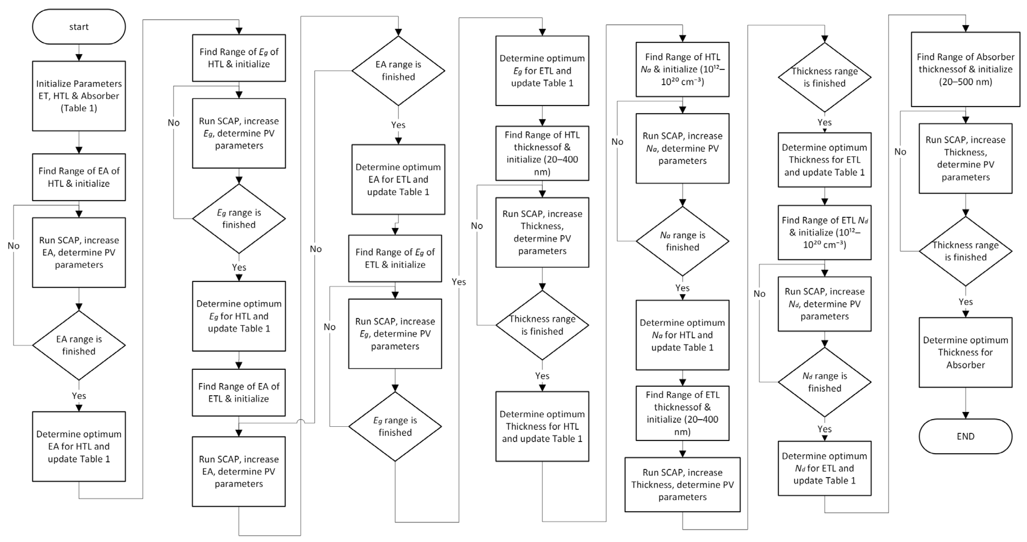
The following simulation processes are carried out to determine the optimal parameters for the electron and hole transport layers in a perovskite solar cell made of MASnIBr2:
  • Using the literature [28,36,37,38,39] as a guide, find the ranges of some parameters for the hole transport layer and the electron transport layer. These parameters include film thickness, doping density, electron affinity, and energy bandgap.
  • Establish an appropriate thickness range for the MASnIBr2 absorber layer, utilizing literature references as a basis [36,37,38,39].
  • Set values at random from the ranges given in Steps 1 and 2 for each of the parameters that were mentioned before.
  • Obtain the maximum power conversion efficiency by simulating the hole transport layer to find its ideal EA. Refine the HTL electron affinity simulation parameter.
  • Find the maximum power conversion efficiency by finding the optimal hole transport layer Eg. Set the simulation’s Eg parameter.
  • Find the best electron transport layer EA that maximizes PCEs. Update the electron transport layer EA simulation parameter.
  • Find the electron transport layer’s ideal Eg that maximizes PCEs. Update the electron transport layer Eg simulation parameter.
  • Find the ideal hole transport layer thickness that maximizes PCEs. Update the thickness of the hole transport layer simulation parameter.
  • Find the optimal hole transport layer Na that maximizes PCEs. Update the Na (hole transport layer) simulation parameter.
  • Gain the maximum power conversion efficiency by finding the ideal thickness of the electron transport layer. Set the electron transport layer thickness parameter in the simulation.
  • Obtain the maximum power conversion efficiency by finding the ideal electron transport layer Nd. Update the Nd (electron transport layer) simulation parameter.
  • Under optimal conditions for the hole transport layer and the electron transport layer, find the MASnIBr2 thickness that maximizes PCEs.
  • Simulate the photocurrent voltage characteristics of the fully optimized device structure.
  • With an optimal hole transport layer and electron transport layer, find out the other responses of the optimized device. End the simulation.
To establish realistic physical restrictions, the parameter ranges for the hole transport layer (HTL), electron transport layer (ETL), and MASnIBr2 absorber were obtained from the published literature. The manual iterative sweep approach was used to optimize the system, with starting values determined heuristically. This procedure included the systematic changes of each parameter (e.g., electron affinity, bandgap, thickness, and doping density) within its specified range while keeping the other parameters constant, as shown in Figure 2. The value with the greatest PCE was chosen before transitioning to the subsequent parameter. This manual method was chosen for its transparency and adherence to SCAPS-1D principles since it allows for the clear separation of individual parameter effects without the intricacies of global optimization methods. Cross-validation confirmed the end device’s performance consistency after sequential optimization.
The accuracy of any simulation is heavily influenced by the reliability of the physical and material parameters used. To ensure precision in this study, all the physical and material properties required by SCAPS-1D were meticulously sourced from the established literature; the complete list of these parameters is provided in Table 1. By reviewing the literature (references [28,36,37,38,39]), the paper methodically optimizes parameters for SCAPS-1D perovskite solar cells based on MASnIBr2. The optimization process begins with the establishment of achievable ranges for crucial variables such as thickness, doping density, electron affinity, and bandgap. To find the best settings, we run iterative simulations that take into account the performance metrics (PCE, Voc, Jsc, FF) and tune each parameter independently while keeping the others constant. The patterns in Figure 3, Figure 4, Figure 5, Figure 6, Figure 7, Figure 8, Figure 9, Figure 10 and Figure 11 show that a systematic method, not random selection, is needed to make sure that device design is repeatable and follows the rules of physics. Table 1’s use of the word “random” indicates a methodical examination of these predefined ranges, not a completely haphazard outcome. This method lowers uncertainty and delivers useful information to help develop lead-free perovskite solar cells.
Additionally, Table 1 presents the initial ranges for key parameters, including HTL and ETL thicknesses (200 nm), sourced from the existing literature. The subsequent iterative optimization was founded on these ranges. Each parameter, such as electron affinity, bandgap, thickness, and doping, was optimized individually during the optimization process, while the other parameters remained at their initial values, as shown in Figure 2.
Similar to many other perovskite materials, the absorber MASnIBr2 exhibits issues such as hysteresis, switchable photocurrent, and a slow photovoltaic response. These undesirable behaviors are largely attributed to the dynamics of defect migration within the material [26,27,49,50]. Such defects typically arise due to various factors, including grain boundaries, fabrication imperfections, and interface dangling bonds, among others [49,50]. To account for these intrinsic defects in the simulation, a uniform defect density was introduced within the bulk region of the perovskite layer with 1015 cm−3, as presented in Table 1. In addition, the interface defect layer parameters are indicated in Table 2. The primary goal of this study is to identify the optimal parameters for the ideal hole and electron transport layers that result in the highest PCE. To achieve this, the simulation incorporates a range of randomly selected parameter values within feasible limits for both transport layers.

3. Results and Discussion

3.1. Electron Affinity Optimization for the Hole Transport Layer
Once the simulation parameters are initialized, the next crucial task is to identify the optimal value of the electron affinity for the hole transport layer in a MASnIBr2-based perovskite solar cell. It is important to find the right electron affinity since it directly affects how well holes can be extracted from the perovskite absorber and stops electrons from flowing back into the HTL. Electron affinity means the difference in energy between the vacuum level and the lowest unoccupied molecular orbital (LUMO). The electron affinity of most hole transport materials that are widely used is usually between 1.5 eV and 4.0 eV, especially when they are coupled with perovskite absorber layers. This range shows how to choose and adjust the HTL parameters to obtain the best performance from solar cells.
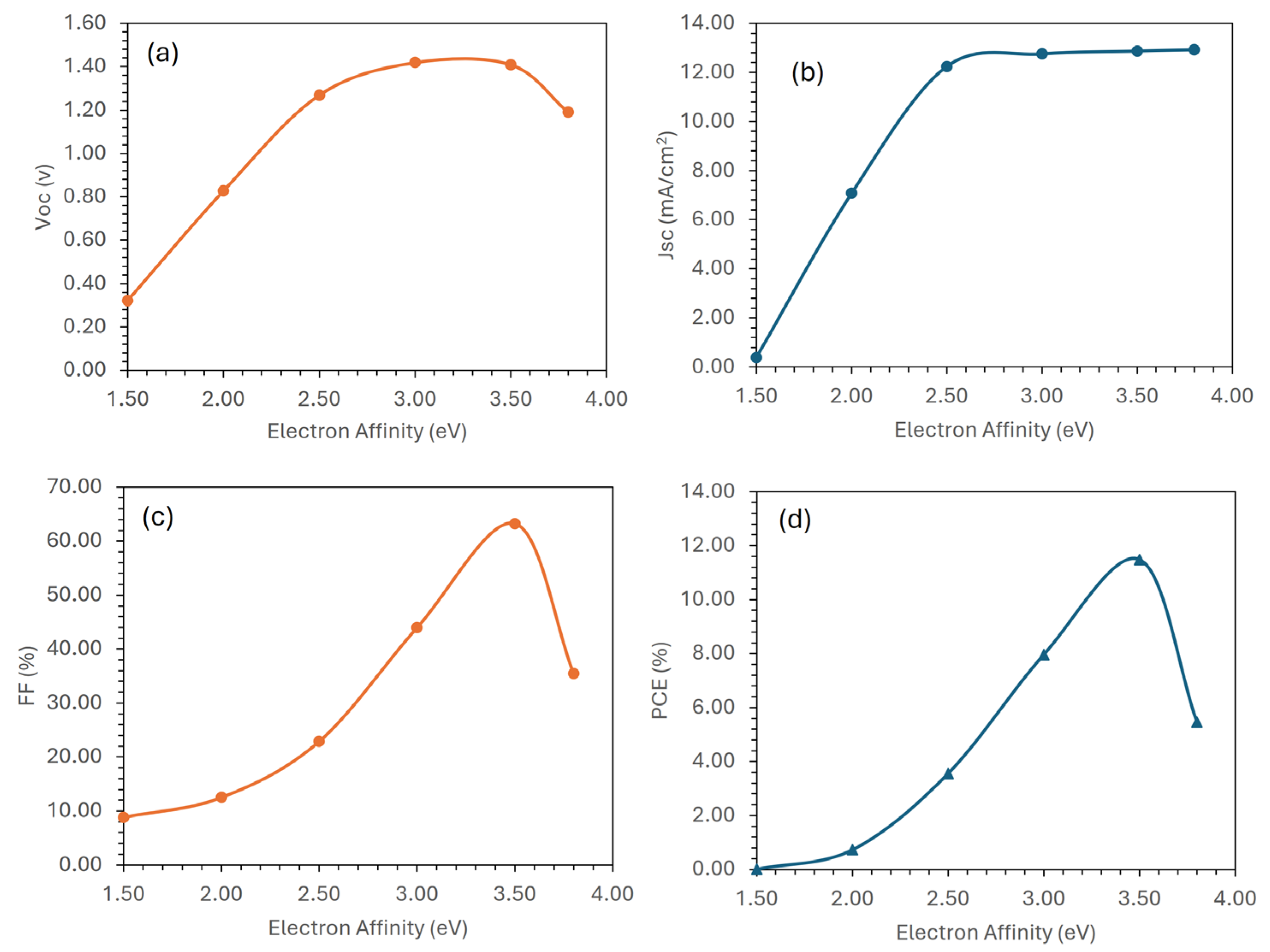
A series of simulations was conducted to investigate the impact of electron affinity on the performance of MASnIBr2-based solar cells. Figure 3 shows how the essential photovoltaic parameters vary as the HTL’s electron affinity changes. From Figure 3a,b, as the electron affinity increases, the open-circuit voltage (Voc) goes up, until it reaches a point where it stops rising at around 3.5 eV electron affinity, while the short-circuit current density (Jsc) behaves nearly the same. Figure 3c,d show that both the fill factor (FF) and power conversion efficiency increase dramatically, peaking at 3.5 eV of electron affinity before beginning a downward trend. This study finds that an electron affinity value of 3.5 eV is the best for the hole transport layer in order to improve the overall performance of the MASnIBr2-based solar cell. The simulation model then uses this value to be implemented in the simulation model to carry out further studies and optimizations.
Figure 3. Photovoltaic performance of the MASnIBr2-based solar cell as a function of electron affinity of an ideal hole transport layer: (a) open-circuit voltage, (b) short-circuit current, (c) fill factor, and (d) power conversion efficiency.
Eng 06 00222 g003

3.2. Energy Bandgap Optimization for the Hole Transport Layer
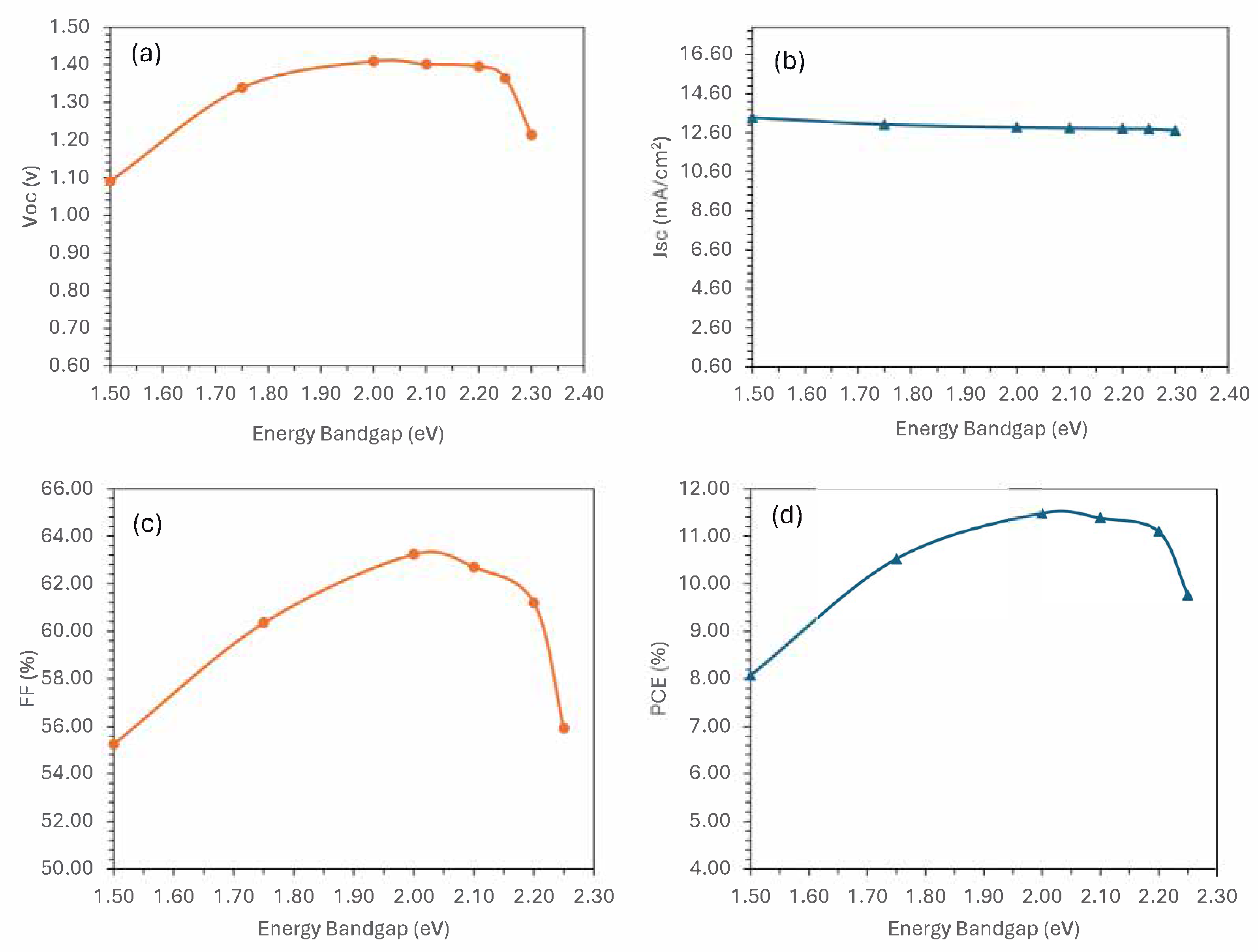
Optimizing the energy bandgap of the hole transport layer is very important for improving the overall performance of perovskite solar cells. A well-tuned bandgap makes sure that light is absorbed efficiently and that the energy levels of the layers next to it, especially the perovskite absorber. A sufficient bandgap makes the material more transparent, which lets the perovskite layer collect more light. Moreover, appropriate bandgap tuning contributes to effective charge separation and transport by aligning the valence band of the HTL with the perovskite layer, facilitating hole extraction while blocking electron recombination [53]. Consequently, to achieve the best power conversion efficiency, it is important to optimize the HTL bandgap.
The variation of key photovoltaic parameters in response to changes in the energy bandgap of an ideal hole transport layer is illustrated in Figure 4. Specifically, Figure 4a,b presents the trends observed in open-circuit voltage and short-circuit current, whereas Figure 4c,d highlights the corresponding changes in fill factor and power conversion efficiency, respectively. While the short-circuit current shows a slight decline, other key parameters such as open-circuit voltage, fill factor, and power conversion efficiency increase steadily as the bandgap approaches 2 eV. Beyond this point, these parameters begin to decline. Among them, power conversion efficiency is the most prominent, reaching its peak at a 2 eV bandgap. Based on these trends, the optimal performance of the hole transport layer is achieved when the bandgap is set to 2 eV and the electron affinity is tuned to 3.5 eV.
Figure 4. Photovoltaic performance of the MASnIBr2-based solar cell as a function of energy bandgap of an ideal hole transport layer: (a) open-circuit voltage, (b) short-circuit current, (c) fill factor, and (d) power conversion efficiency.
Eng 06 00222 g004

3.3. Electron Affinity Optimization for the Electron Transport Layer
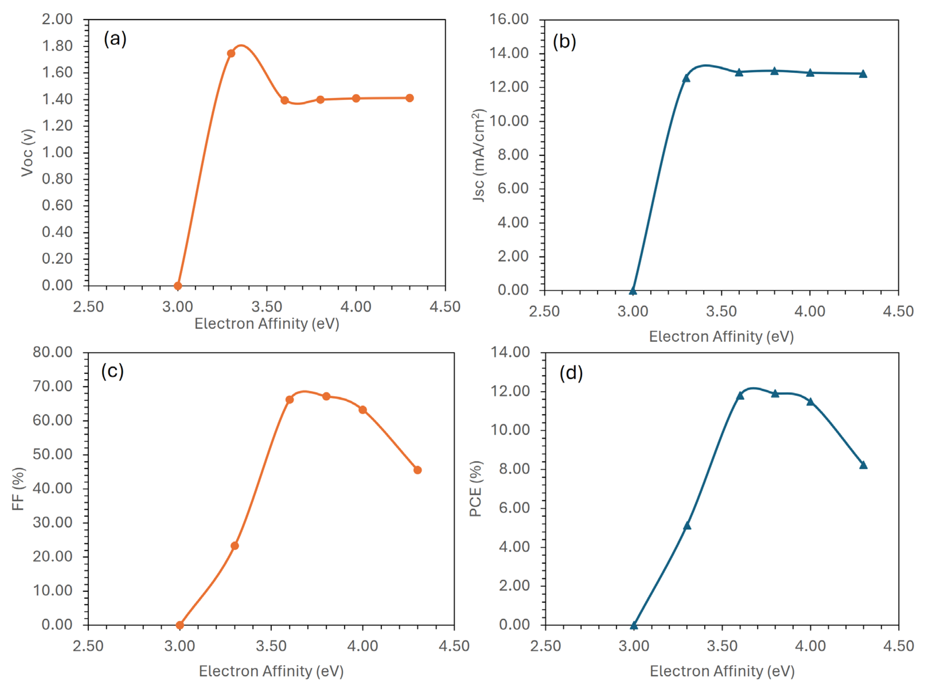
The electron affinity of the electron transport layer is a key factor in determining the efficiency of charge extraction, holding equal importance to that of the hole transport layer. For optimal operation of MASnIBr2-based perovskite solar cells, the ETL must have an electron affinity greater than that of the perovskite absorber (approximately 3.7 eV) to facilitate efficient electron transfer while preventing unwanted recombination. After integrating the previously optimized values for the hole transport layer’s electron affinity and energy bandgap into the simulation model, a systematic investigation was carried out to assess the impact of varying the ETL’s electron affinity. The resulting photovoltaic performance trends are presented in Figure 5.
Figure 5. Photovoltaic performance of the MASnIBr2-based solar cell as a function of electron affinity of an ideal electron transport layer: (a) open-circuit voltage, (b) short-circuit current, (c) fill factor, and (d) power conversion efficiency.
Eng 06 00222 g005
The simulation results show that all photovoltaic parameters exhibit distinct behavior as the ETL electron affinity increases. Initially, both the open-circuit voltage and short-circuit current density rise sharply, indicating improved charge extraction and reduced recombination. However, after reaching a certain threshold, both parameters decrease and then remain nearly constant despite further increases in electron affinity. In contrast, the fill factor and power conversion efficiency continue to rise until they reach their peak at an ETL electron affinity of approximately 3.8 eV. Beyond this point, both begin to decline, likely due to energy level misalignment and increased carrier losses. These findings highlight the importance of carefully tuning the ETL electron affinity, particularly around 3.8 eV, to achieve optimal photovoltaic performance.

3.4. Energy Bandgap Optimization for the Electron Transport Layer

After fine-tuning the electron affinity, the energy bandgap of the electron transport layer emerges as a crucial factor in optimizing multiple interrelated parameters that govern the efficiency of perovskite solar cells. These parameters include minimizing hole injection from the perovskite absorber into the ETL, reducing unwanted optical absorption within the transport layer, enhancing optical reflection back into the perovskite for better photon harvesting, limiting interfacial recombination, and facilitating efficient electron mobility toward the electrode. One of the most essential aspects of this optimization is the effective blocking of minority carriers (holes) from entering the ETL. This can be achieved by engineering the energy bandgap such that the HOMO (Highest Occupied Molecular Orbital) level of the ETL lies significantly below that of the perovskite absorber, whose HOMO is around −5.53 eV. A lower HOMO level in the ETL acts as a barrier, preventing holes from leaking into the ETL and recombining with electrons, a process that would otherwise impair device efficiency. To ensure optimal carrier selectivity and suppress recombination losses, the energy bandgap of the ETL is varied in simulations, and the resulting photovoltaic parameters are analyzed as a function of this variation. Figure 5 presents these results, offering insights into how tuning the ETL bandgap can intentionally position the HOMO level for maximum performance in MASnIBr2-based perovskite solar cells.
Figure 6a illustrates that as the energy bandgap of the electron transport layer increases, the open-circuit voltage experiences a slight rise over a narrow range before stabilizing at a nearly constant level. In contrast, the short-circuit current density initially rises sharply but then shows a gradual decline with further bandgap expansion, as shown in Figure 6b. This trend may result from a band offset between the ETL and the MASnIBr2 absorber. In addition, both the power conversion efficiency, shown in Figure 6d, and the fill factor, shown in Figure 6c, display an initial sharp increase followed by a slower, more gradual improvement as the energy bandgap continues to rise. An energy bandgap of approximately 3.5 eV emerges as the most effective value for maximizing PCEs. The ideal 3.5 eV ETL bandgap effectively suppresses holes while allowing efficient electron transport, while a broader bandgap prevents charge recombination without inducing significant energy misalignment. This optimal value is then implemented in the simulation software for further modeling and device optimization.
Figure 6. Photovoltaic performance of the MASnIBr2-based solar cell as a function of energy bandgap of an ideal electron transport layer: (a) open-circuit voltage, (b) short-circuit current, (c) fill factor, and (d) power conversion efficiency.
Eng 06 00222 g006

3.5. Thickness Optimization for the Hole Transport Layer
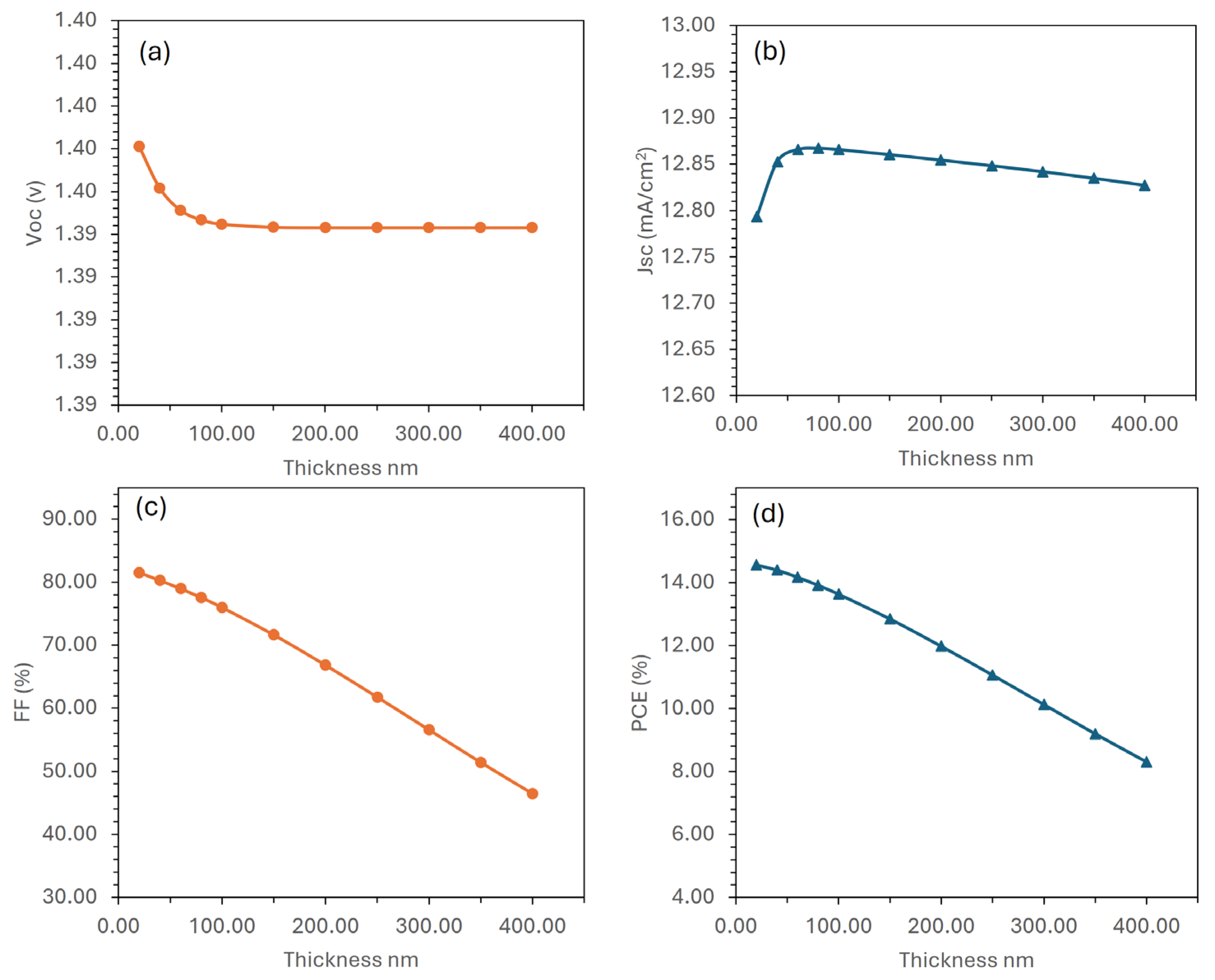
Optimizing the thickness of the hole transport layer is a key consideration in maximizing the efficiency of MASnIBr2-based perovskite solar cells. This physical parameter influences multiple aspects of device operation simultaneously, such as the extraction of photogenerated holes, their transport through the HTL bulk, and the effective collection at the anode. Additionally, interface quality, recombination losses, and series resistance are also closely tied to HTL thickness, making its precise optimization essential for achieving high-performance solar cells [54]. To identify the optimal thickness, photovoltaic performance metrics were evaluated across a range of HTL thickness values. The results of this analysis are presented in Figure 7. These figures clearly demonstrate that all photovoltaic parameters, such as open-circuit voltage, short-circuit current, fill factor, and power conversion efficiency, are sensitive to the HTL thickness. As the thickness increases, a noticeable degradation occurs across all these metrics. According to the data in Figure 7d, the highest power conversion efficiency is achieved when the HTL thickness is 20 nanometers. Beyond this point, the PCE begins to decline. Based on these results, it can be concluded that a 20 nm thick hole transport layer provides the optimal balance between charge extraction, transport, and optical properties for the proposed MASnIBr2-based perovskite solar cell.
Figure 7. Photovoltaic performance of the MASnIBr2-based solar cell as a function of the thickness of an ideal hole transport layer: (a) open-circuit voltage, (b) short-circuit current, (c) fill factor, and (d) power conversion efficiency.
Eng 06 00222 g007

3.6. Doping Density Optimization for the Hole Transport Layer
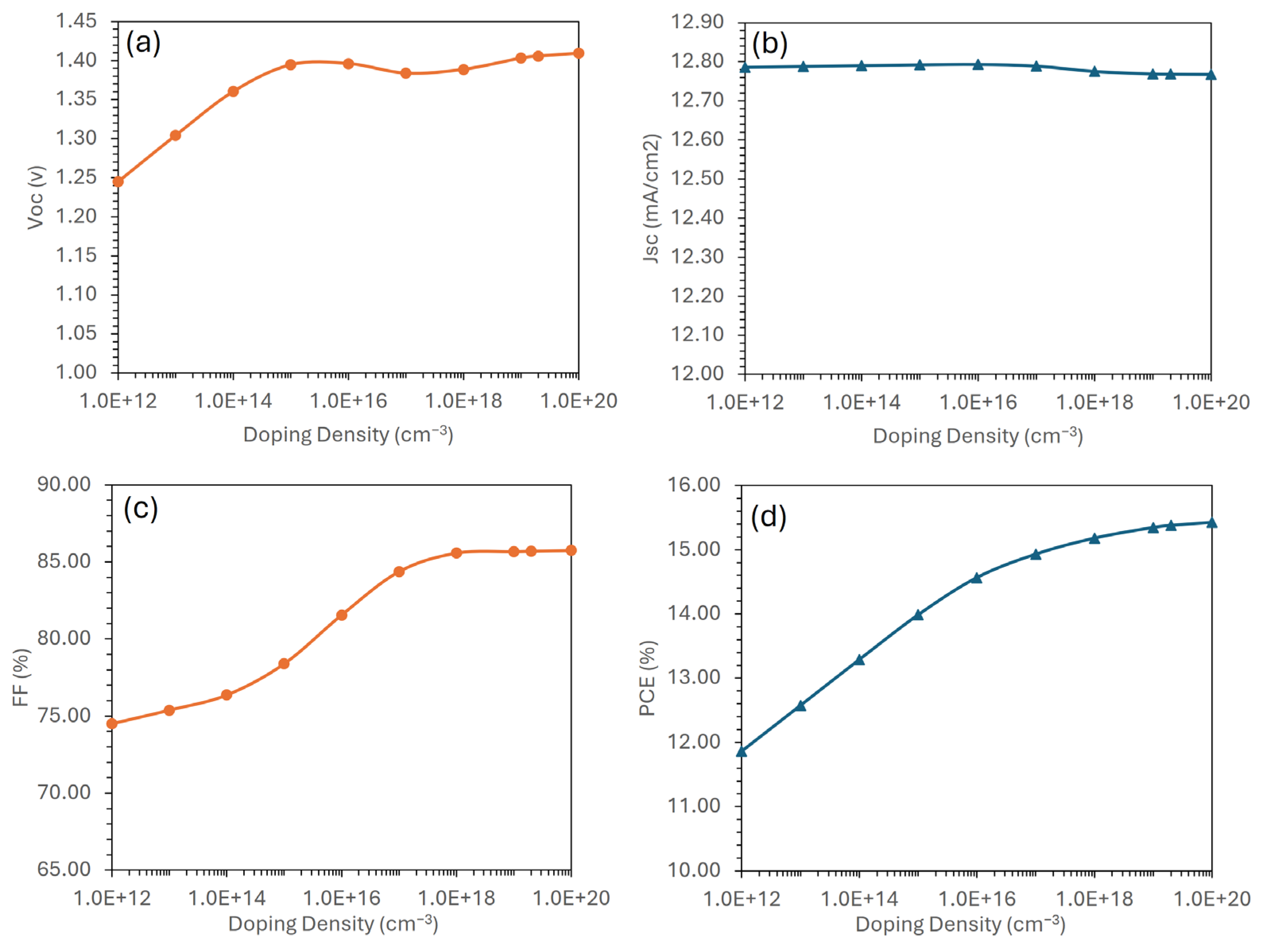
The performance of perovskite solar cells is strongly influenced by the doping levels in both the hole transport layer and the electron transport layer. Doping plays a critical role in determining the electrical properties of the transport layers and, consequently, the overall photovoltaic response. Heavier doping of the HTL enhances its electrical conductivity, which facilitates more efficient charge carrier transport across the layer. It also improves the formation of an ohmic contact with the adjacent electrode, thereby enabling better charge extraction. Furthermore, appropriate doping can reduce the density of trap states at the perovskite/HTL interface, which is essential for minimizing recombination losses and maximizing hole collection efficiency. In addition, optimized doping helps align energy levels between the HTL and the absorber layer, as well as between the HTL and the anode. Such alignment ensures smooth energy band transitions, reducing potential barriers that could otherwise hinder carrier movement. However, excessive doping can be detrimental, as overdoping may introduce adverse effects such as increased parasitic optical absorption, energy level shifts due to the Moss–Burstein effect, and the formation of recombination centers if dopant atoms act as defects [55,56]. These issues ultimately degrade device performance.
To determine the optimal doping concentration, simulations were conducted, and the photovoltaic parameters were analyzed as a function of HTL doping density. As illustrated in Figure 8, key performance indicators such as open-circuit voltage, fill factor, and power conversion efficiency exhibit a positive correlation with increasing doping levels. However, the short-circuit current density remains nearly constant across the tested doping range. The performance peaks at a doping density of approximately 1020 cm−3, which is identified as the ideal level for achieving maximum efficiency in MASnIBr2-based perovskite solar cells. This value is thus adopted for further optimization and device modeling.
Figure 8. Photovoltaic performance of the MASnIBr2-based solar cell as a function of the doping density of an ideal hole transport layer: (a) open-circuit voltage, (b) short-circuit current, (c) fill factor, and (d) power conversion efficiency.
Eng 06 00222 g008

3.7. Thickness Optimization for the Electron Transport Layer

To determine the ideal ETL thickness, we performed simulations and examined the effects of ETL thickness on photovoltaic characteristics. Figure 9 demonstrates that as the thickness of the ETL has increased, the key performance metrics, such as power conversion efficiency, fill factor, open-circuit voltage, and short-circuit current density, have slightly decreased. This may be because as the thickness is increased, series resistance is increased, which may restrict electron flow. Additionally, with the increase in the thickness, the possibility of recombination is also increased, especially if the layer has trap states or defects. As well as with the increase in the ETL thickness, the amount of light that reaches the absorber layer is decreased, which would lower the production of charge carriers [57,58]. The maximum performance of MASnIBr2-based perovskite solar cells is achieved at a thickness of approximately 20 nm, which is the ideal thickness for maximizing efficiency. The device is subsequently further optimized and modeled using this value.
Figure 9. Photovoltaic performance of the MASnIBr2-based solar cell as a function of the thickness of an ideal electron transport layer: (a) open-circuit voltage, (b) short-circuit current, (c) fill factor, and (d) power conversion efficiency.
Eng 06 00222 g009

3.8. Doping Density Optimization for the Electron Transport Layer
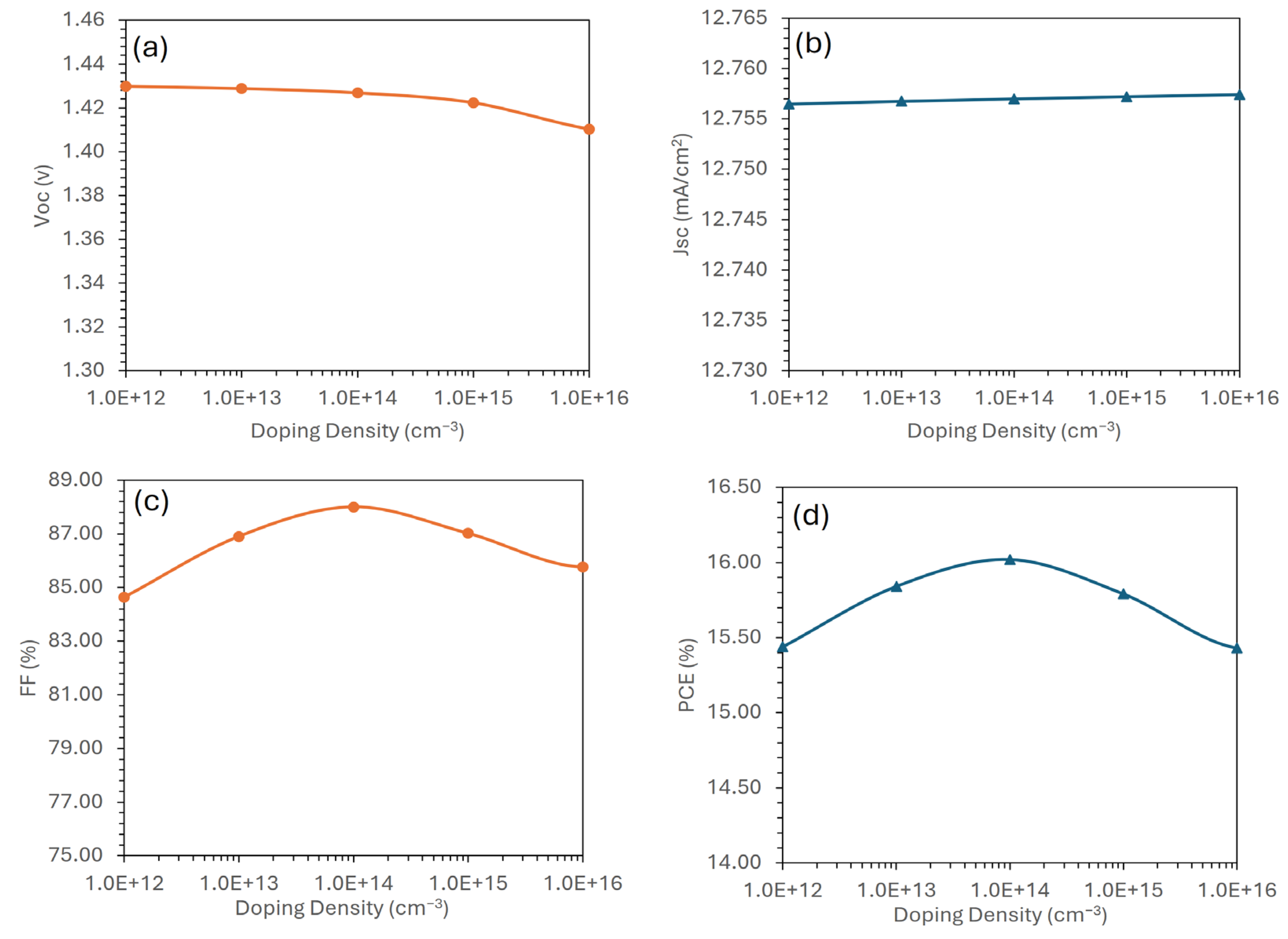
Similar to the case of the hole transport layer, controlling the doping level of the ETL is important as it leads to improving the overall device performance. While a moderate amount of doping enhances electron transport, excessive doping introduces challenges, such as parasitic light absorption, instability, hysteresis in device response, and Moss–Burstein shifts, which can degrade the operational efficiency and stability of the device [59].
Figure 10 shows the effect of various doping levels of the ETL on the photovoltaic performance in a MASnIBr2-based perovskite solar cell. In Figure 10a,b, the open-circuit voltage and short-circuit current are shown to respond differently to changes in doping, while Figure 10c,d show the similar trends of both the fill factor and power conversion efficiency. From Figure 10d, it can be observed that a doping density of 1014 cm−3 has the highest PCE, which is the optimal doping level for the ETL in this device architecture.
Figure 10. Photovoltaic performance of the MASnIBr2-based solar cell as a function of the doping density of an ideal electron transport layer: (a) open-circuit voltage, (b) short-circuit current, (c) fill factor, and (d) power conversion efficiency.
Eng 06 00222 g010

3.9. Thickness Optimization for the MASnIBr2 Absorber Layer
The thickness of the absorber layer plays an important role in the perovskite solar cell performance, as the increase in thickness can raise light absorption and hence increase photogeneration of charge carriers, improving the PCE of the device. On the other hand, the increase in the absorber layer thickness can raise the series resistance and possibility of recombination losses, which may decrease the device performance [60,61]. Thus, it becomes challenging to optimize the thickness of MASnIBr2 for the best photovoltaic response.
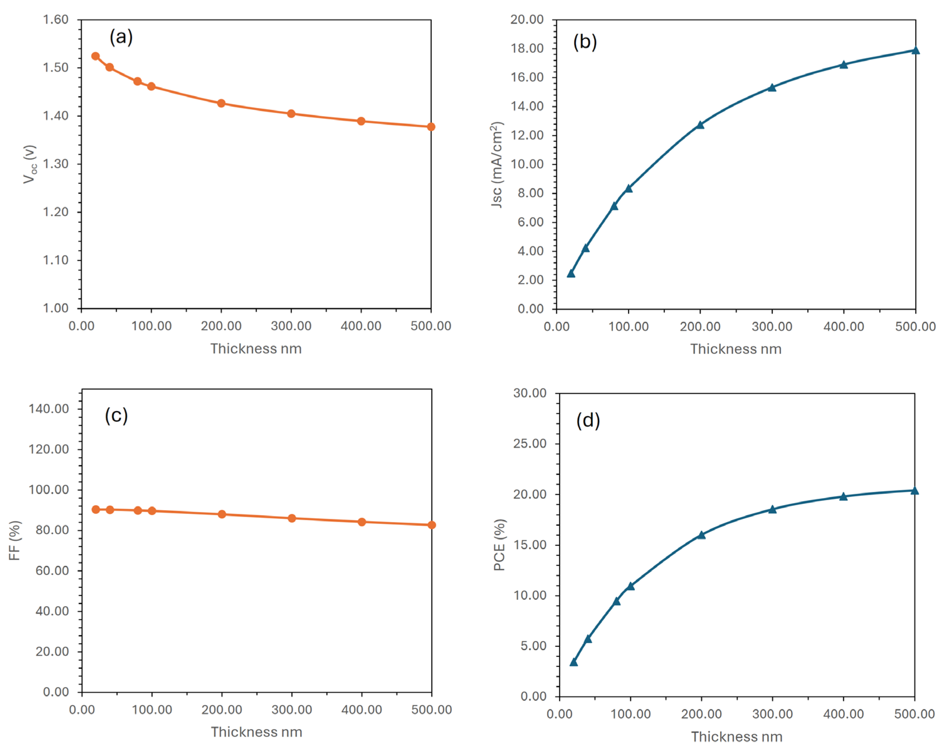
To determine the optimal thickness of the MASnIBr2 absorber layer, the photovoltaic performance of the proposed perovskite solar cells was evaluated across various absorber thicknesses, as shown in Figure 11. The results show that as the absorber thickness increases, the open-circuit voltage and the fill factor decrease, which may be due to the increase in series resistance. In addition, the short-circuit current density and power-conversion efficiency increased as the absorber thickness increased. This enhancement may be due to enhanced light absorption as the thickness is increased. However, beyond approximately 500 nm, the PCE nearly begins to saturate. It is possible to explain the trade-off in terms of absorber thickness: thicker layers increase recombination (which lowers voltage) but also increase light absorption (which increases current). The ideal equilibrium is attained at 500 nm. These improvements provide a more thorough understanding of the design principles that explain the enhanced performance of the proposed solar cell. As the PCE is a key indicator of device performance, 500 nm can be considered the optimal absorber layer thickness for achieving the highest efficiency in the proposed MASnIBr2-based perovskite solar cell design.
Figure 11. Photovoltaic performance of the MASnIBr2-Based solar cell as a function of the thickness of an MASnIBr2 absorber layer: (a) open-circuit voltage, (b) short-circuit current, (c) fill factor, and (d) power conversion efficiency.
Eng 06 00222 g011

3.10. Performance Overview of the Optimized Perovskite Solar Cell

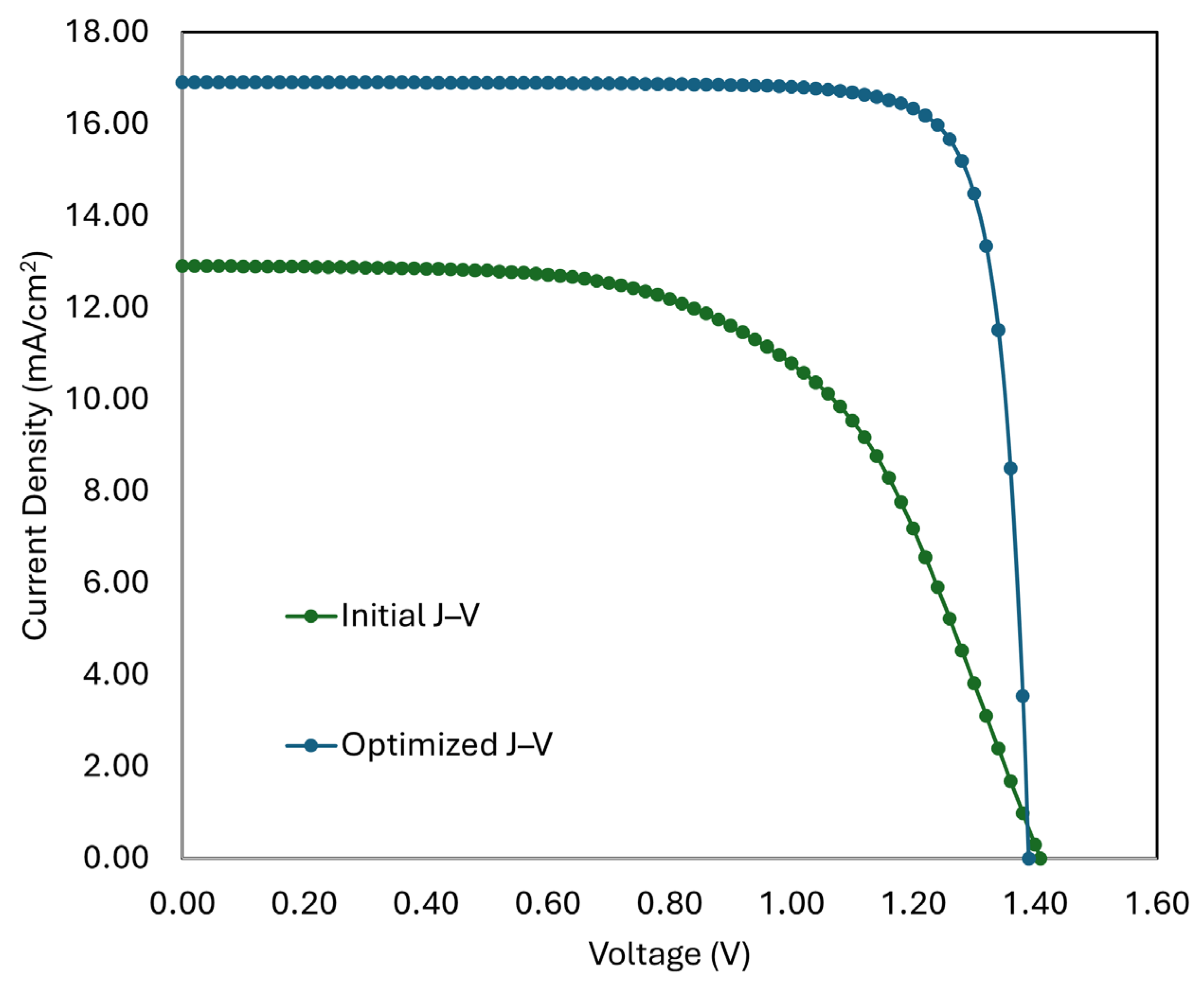
The simulation process began with the individual optimization of both transport layers in terms of bandgap, electron affinity, film thickness, and doping level. The optimized perovskite achieved in this study has an ideal HTL electron affinity of 3.5 eV with an energy bandgap of 2 eV, while they are 3.8 eV and 3.5 eV, respectively, for an ideal ETL. After achieving these ideal conditions, the current–voltage (J–V) characteristics were simulated for a device incorporating the optimized hole and electron transport layers. The initial unoptimized structure achieves a lower efficiency (approximately 10% according to referenced literature values for MASnIBr2), as illustrated in Figure 12. However, the fully optimized device (Figure 12) achieves a peak power conversion efficiency (PCE) of 20.42% with improved J–V characteristics (Jsc = 17.91 mA/cm2, Voc = 1.38 V, FF = 82.75%). This would enable a more comprehensive understanding of the manner in which the device’s performance is jointly improved by each optimized parameter (HTL/ETL characteristics, absorber thickness).
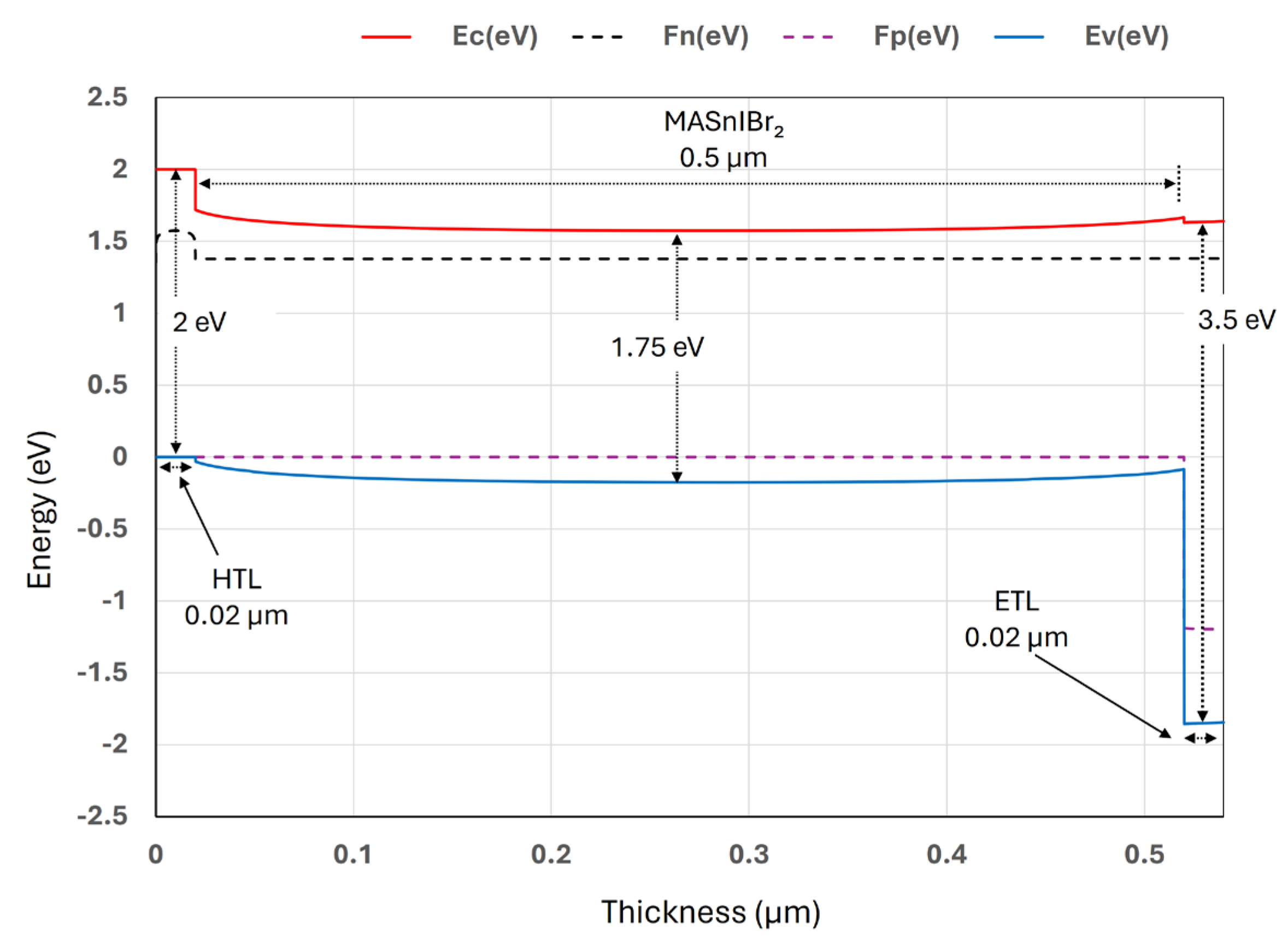
Figure 13 represents the energy band diagram of a perovskite solar cell, comprising the structure HTL (0.02 µm)/MASnIBr2 perovskite (0.5 µm)/ETL (0.02 µm). The diagram depicts the main energy levels, including the conduction band (Ec), the valence band (Ev), and the quasi-Fermi levels for the n and p regions (Fn and Fp, respectively). The perovskite has a bandgap of approximately 1.75 eV, with the valence band maximum (VBM) at about −0.25 eV and the conduction band minimum (CBM) near 1.50 eV. At the HTL/perovskite interface, the valence band offset is around 0.03 eV and the conduction band offset is approximately 0.25 eV, providing barriers that block undesired carrier flow while supporting selective extraction. At the perovskite/ETL interface, the conduction band offset is close to 0.02 eV, ensuring efficient electron transfer, while the valence band offset is about 1.75 eV, strongly blocking holes. The distortion of bands at the interfaces caused by electric fields indicates the presence of an intrinsic field that promotes charge separation. The thickness of the perovskite layer enhances light absorption and carrier collection, while the ultra-thin HTL and ETL help minimize resistive losses [62].

3.11. Impact of Defect Density on the Performance of the MASnIBr2 Absorber Layer

The MASnIBr2 defect physics applies to the oxidation of Sn2+ to Sn4+ and its role in producing self-p-doping effects, potentially leading to intrinsic defect concentrations that surpass the initial estimate of 1015 cm−3. To evaluate the impact on device performance, we conducted simulations of the above device incorporating deeper acceptor trap states near the mid-gap region to accurately represent Sn4+-related defects, as well as increased defect densities (1012–1018 cm−3) in specific instances, as shown in Figure 14 [36,63]. The recent findings demonstrate the influence of Sn-related defects on device photovoltaic parameters. This characterization provides a more precise understanding of deterioration and charge recombination pathways. It can be seen from Figure 14 that as defect density rises, all key performance metrics decline. The fill factor (FF), which is a critical factor in cell efficiency, is the one that changes the most. The FF falls to about 37% at 1 × 1018 cm−3 and levels off at about 80% for defect concentrations below 1 × 1015 cm−3. In the same range, the power conversion efficiency drops from 26.61% to only 2.65%. These results show that increased defect densities decrease the charge carrier diffusion length and speed up carrier recombination in the absorber, which directly lowers the efficiency of the device [64,65,66].

3.12. Comparison with Previous Results

The performance of MASnIxBr3-x based perovskite solar cells has shown large changes and steady improvements, mostly because of the choice of materials for the hole transport layer and electron transport layer, as shown in Table 3. In [37], the MASnIBr2-based perovskite solar cell with Spiro-OMeTAD as the HTL and TiO2 as the ETL had a PCE of 5.73%. Some later configurations, like the ones from [36,38], were even less efficient, which may be due to less optimized designs. There were considerable improvements in [67], with the use of PEDOT:PSS as the HTL and TiO2 as the ETL raising the efficiency to 16.07%. In [39,68], improvements brought efficiencies of 11.74% for MASnIBr2 and 9.44% for MASnI3 using Spiro-OMeTAD and TiO2 as the HTL and the ETL, respectively. MASnI3 with CuSbS2 as the HTL and C60 as the ETL reached 20.7% in [69], while MASnBr3 with Cu2O and WS2 as the HTL and the ETL, respectively, reached 22.71% in [70]. In the present work, MASnIBr2 with ideal HTL and ETL materials attained a PCE of 20.43%.

4. Conclusions

In this study, an extensive simulation and design of each of the crucial transport layer parameters, such as doping density, film thickness, energy bandgap, and electron affinity, was independently changed and evaluated using comprehensive device simulations. The results show that there is an optimal electron transport layer with an electron affinity of 3.8 eV and a bandgap of 3.5 eV, as well as an ideal hole transport layer with an electron affinity of 3.5 eV and a bandgap of 2.0 eV. In addition, it was discovered that the optimal absorber layer thickness is 500 nm for the highest PCE. For given optimal parameter values, the device achieves a peak power conversion efficiency of 20.42% with an open-circuit voltage of roughly 1.38 V, a short-circuit current density of 17.91 mA cm−2, and a fill factor of 82.75%. The results of these investigations are expected to guide future research endeavors and provide a quantitative framework for the design of lead-free, high-efficiency perovskite photovoltaics.

Funding

This research received no external funding.

Data Availability Statement

Data is contained within the article.

Acknowledgments

We acknowledge that all simulations in this work were performed using the SCAPS-1D program developed by Marc Burgelman et al. (University of Gent).

Conflicts of Interest

The authors declare no conflicts of interest.

References

  1. Singh, M.; Akash; Tiwari, J.P. Solar Cells Based on Pb-Free and Perovskite-Inspired Materials: Futuristic of Perovskite Solar Cells. ACS Appl. Energy Mater. 2024, 7, 10212–10229. [Google Scholar] [CrossRef]
  2. Zhou, J.; Fu, S.; Zhou, S.; Huang, L.; Wang, C.; Guan, H.; Pu, D.; Cui, H.; Wang, C.; Wang, T.; et al. Mixed Tin-Lead Perovskites with Balanced Crystallization and Oxidation Barrier for All-Perovskite Tandem Solar Cells. Nat. Commun. 2024, 15, 2324. [Google Scholar] [CrossRef] [PubMed]
  3. Shao, M.; Bie, T.; Yang, L.; Gao, Y.; Jin, X.; He, F.; Zheng, N.; Yu, Y.; Zhang, X. Over 21% Efficiency Stable 2D Perovskite Solar Cells. Adv. Mater. 2022, 34, 2107211. [Google Scholar] [CrossRef] [PubMed]
  4. Liu, J.; Aydin, E.; Yin, J.; De Bastiani, M.; Isikgor, F.H.; Rehman, A.U.; Yengel, E.; Ugur, E.; Harrison, G.T.; Wang, M.; et al. 28.2%-Efficient, Outdoor-Stable Perovskite/Silicon Tandem Solar Cell. Joule 2021, 5, 3169–3186. [Google Scholar] [CrossRef]
  5. Ding, G.; Zheng, Y.; Xiao, X.; Cheng, H.; Zhang, G.; Shi, Y.; Shao, Y. Sustainable Development of Perovskite Solar Cells: Keeping a Balance between Toxicity and Efficiency. J. Mater. Chem. A 2022, 10, 8159–8171. [Google Scholar] [CrossRef]
  6. Zhang, W.; Cai, Y.; Liu, H.; Xia, Y.; Cui, J.; Shi, Y.; Chen, R.; Shi, T.; Wang, H.L. Organic-Free and Lead-Free Perovskite Solar Cells with Efficiency over 11%. Adv. Energy Mater. 2022, 12, 2202491. [Google Scholar] [CrossRef]
  7. Wu, C.; Zhang, Q.; Liu, Y.; Luo, W.; Guo, X.; Huang, Z.; Ting, H.; Sun, W.; Zhong, X.; Wei, S.; et al. The Dawn of Lead-Free Perovskite Solar Cell: Highly Stable Double Perovskite Cs2AgBiBr6 Film. Adv. Sci. 2018, 5, 1700759. [Google Scholar] [CrossRef]
  8. Bibi, A.; Lee, I.; Nah, Y.; Allam, O.; Kim, H.; Quan, L.N.; Tang, J.; Walsh, A.; Jang, S.S.; Sargent, E.H.; et al. Lead-Free Halide Double Perovskites: Toward Stable and Sustainable Optoelectronic Devices. Mater. Today 2021, 49, 123–144. [Google Scholar] [CrossRef]
  9. Ustinova, M.I.; Babenko, S.D.; Luchkin, S.Y.; Talalaev, F.S.; Anokhin, D.V.; Olthof, S.; Troshin, P.A. Correction: Experimental Evaluation of Indium(i) Iodide as a Lead-Free Perovskite-Inspired Material for Photovoltaic Applications. J. Mater. Chem. C Mater. 2023, 11, 2398. [Google Scholar] [CrossRef]
  10. Giustino, F.; Snaith, H.J. Toward Lead-Free Perovskite Solar Cells. ACS Energy Lett. 2016, 1, 1233–1240. [Google Scholar] [CrossRef]
  11. Mora-Herrera, D.; Pal, M. Path toward the Performance Upgrade of Lead-Free Perovskite Solar Cells Using Cu2ZnSn1- XGexS4as a Hole Transport Layer: A Theoretical Simulation Approach. J. Phys. Chem. C 2022, 126, 5847–5862. [Google Scholar] [CrossRef]
  12. Bello, O.O.; Emetere, M.E. Progress and Limitation of Lead-Free Inorganic Perovskites for Solar Cell Application. Sol. Energy 2022, 243, 370–380. [Google Scholar] [CrossRef]
  13. Moiz, S.A.; Alahmadi, A.N.M. Design of Dopant and Lead-Free Novel Perovskite Solar Cell for 16.85% Efficiency. Polymers 2021, 13, 2110. [Google Scholar] [CrossRef]
  14. Moiz, S.A.; Alahmadi, A.N.M.; Aljohani, A.J. Design of a Novel Lead-Free Perovskite Solar Cell for 17.83% Efficiency. IEEE Access 2021, 9, 54254–54263. [Google Scholar] [CrossRef]
  15. Moiz, S.A.; Alahmadi, A.N.M.; Alshaikh, M.S. Lead-Free FACsSnI3 Based Perovskite Solar Cell: Designing Hole and Electron Transport Layer. Nanomaterials 2023, 13, 1524. [Google Scholar] [CrossRef] [PubMed]
  16. Al-Amri, A.M.; Cheng, B.; He, J.H. Perovskite Methylammonium Lead Trihalide Heterostructures: Progress and Challenges. IEEE Trans. Nanotechnol. 2019, 18, 1–12. [Google Scholar] [CrossRef]
  17. Treglia, A.; Ambrosio, F.; Martani, S.; Folpini, G.; Barker, A.J.; Albaqami, M.D.; De Angelis, F.; Poli, I.; Petrozza, A. Effect of Electronic Doping and Traps on Carrier Dynamics in Tin Halide Perovskites. Mater. Horiz. 2022, 9, 1763–1773. [Google Scholar] [CrossRef]
  18. Jokar, E.; Chien, C.H.; Tsai, C.M.; Fathi, A.; Diau, E.W.G. Robust Tin-Based Perovskite Solar Cells with Hybrid Organic Cations to Attain Efficiency Approaching 10%. Adv. Mater. 2019, 31, e1804835. [Google Scholar] [CrossRef]
  19. Ricciarelli, D.; Meggiolaro, D.; Ambrosio, F.; De Angelis, F. Instability of Tin Iodide Perovskites: Bulk p-Doping versus Surface Tin Oxidation. ACS Energy Lett. 2020, 5, 2787–2795. [Google Scholar] [CrossRef]
  20. Ke, W.; Stoumpos, C.C.; Kanatzidis, M.G. “Unleaded” Perovskites: Status Quo and Future Prospects of Tin-Based Perovskite Solar Cells. Adv. Mater. 2019, 31, e1803230. [Google Scholar] [CrossRef]
  21. Jin, Z.; Yu, B.B.; Liao, M.; Liu, D.; Xiu, J.; Zhang, Z.; Lifshitz, E.; Tang, J.; Song, H.; He, Z. Enhanced Efficiency and Stability in Sn-Based Perovskite Solar Cells with Secondary Crystallization Growth. J. Energy Chem. 2021, 54, 414–421. [Google Scholar] [CrossRef]
  22. Macdonald, T.J.; Lanzetta, L.; Liang, X.; Ding, D.; Haque, S.A. Engineering Stable Lead-Free Tin Halide Perovskite Solar Cells: Lessons from Materials Chemistry. Adv. Mater. 2023, 35, 2206684. [Google Scholar] [CrossRef] [PubMed]
  23. Solis, O.E.; Mínguez-Avellán, M.; Betancur, P.F.; Sánchez-Alarcón, R.I.; Rodriguez, I.; Martínez-Pastor, J.P.; Ripolles, T.S.; Abargues, R.; Boix, P.P. Adjusting the Crystallization of Tin Perovskites through Thiophene Additives for Improved Photovoltaic Stability. ACS Energy Lett. 2024, 9, 5288–5295. [Google Scholar] [CrossRef] [PubMed]
  24. Yang, C.; Hu, W.; Liu, J.; Han, C.; Gao, Q.; Mei, A.; Zhou, Y.; Guo, F.; Han, H. Achievements, Challenges, and Future Prospects for Industrialization of Perovskite Solar Cells. Light. Sci. Appl. 2024, 13, 227. [Google Scholar] [CrossRef]
  25. Song, D.; Shin, S.W.; Wu, H.-P.; Diau, E.W.-G.; Correa-Baena, J.-P. Toward Maximizing Hole Selection with Self-Assembled Monolayers in Sn-Based Perovskite Solar Cells. ACS Energy Lett. 2025, 10, 1292–1312. [Google Scholar] [CrossRef]
  26. Shukla, A.; Khadka, D.B.; Li, C.; Rikukawa, M.; Takeoka, Y.; Sahara, R.; Yanagida, M.; Shirai, Y. Defect Mitigation via Fullerene-Based Functional Additives for Enhanced Efficiency and Stability in Tin Perovskite Solar Cells. J. Mater. Chem. A Mater. 2025, 13, 23487–23498. [Google Scholar] [CrossRef]
  27. Ke, W.; Kanatzidis, M.G. Prospects for Low-Toxicity Lead-Free Perovskite Solar Cells. Nat. Commun. 2019, 10, 965. [Google Scholar] [CrossRef]
  28. Wang, M.; Wang, W.; Ma, B.; Shen, W.; Liu, L.; Cao, K.; Chen, S.; Huang, W. Lead-Free Perovskite Materials for Solar Cells. Nano-Micro Letters. 2021, 13, 1–36. [Google Scholar] [CrossRef]
  29. Wang, Y.; Li, T.; Chen, X.; Zhang, L. High-Performance Flexible Lead-Free Perovskite Solar Cells Based on Tin-Halide Perovskite Films Doped by Reductant Metal Halide. Mater. Lett. 2022, 321, 132460. [Google Scholar] [CrossRef]
  30. Ozório, M.S.; Srikanth, M.; Besse, R.; Da Silva, J.L.F. The Role of the A-Cations in the Polymorphic Stability and Optoelectronic Properties of Lead-Free ASnI3perovskites. Phys. Chem. Chem. Phys. 2021, 23, 2286–2297. [Google Scholar] [CrossRef]
  31. Shi, T.; Zhang, H.S.; Meng, W.; Teng, Q.; Liu, M.; Yang, X.; Yan, Y.; Yip, H.L.; Zhao, Y.J. Effects of Organic Cations on the Defect Physics of Tin Halide Perovskites. J. Mater. Chem. A Mater. 2017, 5, 15124–15129. [Google Scholar] [CrossRef]
  32. Saski, M.; Prochowicz, D.; Marynowski, W.; Lewiński, J. Mechanosynthesis, Optical, and Morphological Properties of MA, FA, Cs-SnX3 (X = I, Br) and Phase-Pure Mixed-Halide MASnIxBr3–x Perovskites. Eur. J. Inorg. Chem. 2019, 2019, 2680–2684. [Google Scholar] [CrossRef]
  33. Şen, E.; Kaleli, M.; Aldemir, D.A.; Lapa, H.E. Investigation of MASnIxBr3−x (x = 3, 2, 1, 0) Perovskite Thin Films Produced by Ultrasonic Spray Pyrolysis Method. Arab. J. Sci. Eng. 2024, 49, 10085–10094. [Google Scholar] [CrossRef]
  34. Al Jame, H.; Sarker, S.; Islam, S.; Islam, T.; Rauf, A.; Ahsan, S.; Nishat, S.S.; Jani, R.; Shorowordi, K.; Carbonara, J.; et al. Supervised Machine Learning-Aided SCAPS-Based Quantitative Analysis for the Discovery of Optimum Bromine Doping in Methylammonium Tin-Based Perovskite (MASnI3–XBrx). ACS Appl. Mater. Interfaces 2022, 14, 502–516. [Google Scholar] [CrossRef]
  35. Chen, N.; Li, Y.; Lv, S.; Hu, L.; Lv, B.; Nie, Q.; Yan, B. Co-Treatment of an Inorganic Additive SnF2 and an Organic Additive P(VDF-TrFE) for Improving the Performances of MASnBr3 Films. Opt. Mater. 2024, 147, 114721. [Google Scholar] [CrossRef]
  36. Xiao, M.; Gu, S.; Zhu, P.; Tang, M.; Zhu, W.; Lin, R.; Chen, C.; Xu, W.; Yu, T.; Zhu, J. Tin-Based Perovskite with Improved Coverage and Crystallinity through Tin-Fluoride-Assisted Heterogeneous Nucleation. Adv. Opt. Mater. 2018, 6, 1700615. [Google Scholar] [CrossRef]
  37. Hao, F.; Stoumpos, C.C.; Cao, D.H.; Chang, R.P.H.; Kanatzidis, M.G. Lead-Free Solid-State Organic-Inorganic Halide Perovskite Solar Cells. Nat. Photonics 2014, 8, 489–494. [Google Scholar] [CrossRef]
  38. Nguyen, B.P.; Shin, D.; Jung, H.R.; Kim, J.; Nguyen, T.T.T.; Yoon, S.; Yi, Y.; Jo, W. Phase Formation and Local Charge Transport of Lead-Free CH3NH3Sn(I1−xBrx)3 (0 ≤ x ≤ 1)Perovskite Solar Cells Fabricated by Solvent Optimization. Sol. Energy 2019, 186, 136–144. [Google Scholar] [CrossRef]
  39. Abdelaziz, S.; Zekry, A.; Shaker, A.; Abouelatta, M. Investigation of Lead-Free MASnI3-MASnIBr2 Tandem Solar Cell: Numerical Simulation. Opt. Mater. 2022, 123, 111893. [Google Scholar] [CrossRef]
  40. Burgelman, M.; Nollet, P.; Degrave, S. Modelling Polycrystalline Semiconductor Solar Cells. Thin Solid Film. 2000, 361, 527–532. [Google Scholar] [CrossRef]
  41. Alahmadi, A.N.M. Design of an Efficient PTB7:PC70BM-Based Polymer Solar Cell for 8% Efficiency. Polymers 2022, 14, 889. [Google Scholar] [CrossRef]
  42. Liu, F.; Zhu, J.; Wei, J.; Li, Y.; Lv, M.; Yang, S.; Zhang, B.; Yao, J.; Dai, S. Numerical Simulation: Toward the Design of High-Efficiency Planar Perovskite Solar Cells. Appl. Phys. Lett. 2014, 104, 253508. [Google Scholar] [CrossRef]
  43. Decock, K.; Zabierowski, P.; Burgelman, M. Modeling Metastabilities in Chalcopyrite-Based Thin Film Solar Cells. J. Appl. Phys. 2012, 111, 043703. [Google Scholar] [CrossRef]
  44. Burgelman, M.; Decock, K.; Khelifi, S.; Abass, A. Advanced Electrical Simulation of Thin Film Solar Cells. Thin Solid Film. 2013, 535, 296–301. [Google Scholar] [CrossRef]
  45. Burgelman, M.; Verschraegen, J.; Degrave, S.; Nollet, P. Modeling Thin-Film PV Devices. Prog. Photovolt. Res. Appl. 2004, 12, 143–153. [Google Scholar] [CrossRef]
  46. Verschraegen, J.; Burgelman, M. Numerical Modeling of Intra-Band Tunneling for Heterojunction Solar Cells in Scaps. Thin Solid Film. 2007, 515, 6276–6279. [Google Scholar] [CrossRef]
  47. Saidarsan, A.; Guruprasad, S.; Malik, A.; Basumatary, P.; Ghosh, D.S. A Critical Review of Unrealistic Results in SCAPS-1D Simulations: Causes, Practical Solutions and Roadmap Ahead. Sol. Energy Mater. Sol. Cells 2025, 279, 113230. [Google Scholar] [CrossRef]
  48. Moiz, S.A.; Alzahrani, M.S.; Alahmadi, A.N.M. Electron Transport Layer Optimization for Efficient PTB7:PC70BM Bulk-Heterojunction Solar Cells. Polymers 2022, 14, 3610. [Google Scholar] [CrossRef] [PubMed]
  49. Momblona, C.; Gil-Escrig, L.; Bandiello, E.; Hutter, E.M.; Sessolo, M.; Lederer, K.; Blochwitz-Nimoth, J.; Bolink, H.J. Efficient Vacuum Deposited P-i-n and n-i-p Perovskite Solar Cells Employing Doped Charge Transport Layers. Energy Env. Sci. 2016, 9, 3456–3463. [Google Scholar] [CrossRef]
  50. Liu, Z.; Zhu, A.; Cai, F.; Tao, L.M.; Zhou, Y.; Zhao, Z.; Chen, Q.; Cheng, Y.B.; Zhou, H. Nickel Oxide Nanoparticles for Efficient Hole Transport in P-i-n and n-i-p Perovskite Solar Cells. J. Mater. Chem. A Mater. 2017, 5, 6597–6605. [Google Scholar] [CrossRef]
  51. Raoui, Y.; Ez-Zahraouy, H.; Tahiri, N.; El Bounagui, O.; Ahmad, S.; Kazim, S. Performance Analysis of MAPbI3 Based Perovskite Solar Cells Employing Diverse Charge Selective Contacts: Simulation Study. Sol. Energy 2019, 193, 948–955. [Google Scholar] [CrossRef]
  52. Hossain, M.K.; Toki, G.F.I.; Kuddus, A.; Rubel, M.H.K.; Hossain, M.M.; Bencherif, H.; Rahman, M.F.; Islam, M.R.; Mushtaq, M. An Extensive Study on Multiple ETL and HTL Layers to Design and Simulation of High-Performance Lead-Free CsSnCl3-Based Perovskite Solar Cells. Sci. Rep. 2023, 13, 2521. [Google Scholar] [CrossRef]
  53. Karimi, E.; Ghorashi, S.M.B. Investigation of the Influence of Different Hole-Transporting Materials on the Performance of Perovskite Solar Cells. Optik 2017, 130, 650–658. [Google Scholar] [CrossRef]
  54. Bag, A.; Radhakrishnan, R.; Nekovei, R.; Jeyakumar, R. Effect of Absorber Layer, Hole Transport Layer Thicknesses, and Its Doping Density on the Performance of Perovskite Solar Cells by Device Simulation. Sol. Energy 2020, 196, 177–182. [Google Scholar] [CrossRef]
  55. Anik, M.H.K.; Mahmud, S.; Islam, M.A.; Talukder, H.; Biswas, S.K.; Islam, S. Comparative Performance Analysis and Material Exploration of ECO-Friendly Highly Efficient Perovskite Solar Cells. Semicond. Sci. Technol. 2022, 37, 115004. [Google Scholar] [CrossRef]
  56. Mahmood, K.; Sarwar, S.; Mehran, M.T. Current Status of Electron Transport Layers in Perovskite Solar Cells: Materials and Properties. RSC Adv. 2017, 7, 17044–17062. [Google Scholar] [CrossRef]
  57. Bulowski, W.; Szwanda, A.; Gawlińska-Nęcek, K.; Panek, P.; Lipiński, M.; Janusz-Skuza, M.; Szczerba, M.J.; Majchrowicz, Ł.; Mahapatra, A.; Prochowicz, D.; et al. Optimization of the ETL Titanium Dioxide Layer for Inorganic Perovskite Solar Cells. J. Mater. Sci. 2024, 59, 7283–7298. [Google Scholar] [CrossRef]
  58. Gulomov, J.; Accouche, O.; Aliev, R.; Neji, B.; Ghandour, R.; Gulomova, I.; Azab, M. Geometric Optimization of Perovskite Solar Cells with Metal Oxide Charge Transport Layers. Nanomaterials 2022, 12, 2692. [Google Scholar] [CrossRef]
  59. Wang, Z.K.; Liao, L.S. Doped Charge-Transporting Layers in Planar Perovskite Solar Cells. Adv. Opt. Mater. 2018, 6, 1800276. [Google Scholar] [CrossRef]
  60. Hossain, M.K.; Bhattarai, S.; Arnab, A.A.; Mohammed, M.K.A.; Pandey, R.; Ali, M.H.; Rahman, M.F.; Islam, M.R.; Samajdar, D.P.; Madan, J.; et al. Harnessing the Potential of CsPbBr3-Based Perovskite Solar Cells Using Efficient Charge Transport Materials and Global Optimization. RSC Adv. 2023, 13, 21044–21062. [Google Scholar] [CrossRef]
  61. Mortadi, A.; El Hafidi, E.; Monkade, M.; El Moznine, R. Investigating the Influence of Absorber Layer Thickness on the Performance of Perovskite Solar Cells: A Combined Simulation and Impedance Spectroscopy Study. Mater. Sci. Energy Technol. 2024, 7, 158–165. [Google Scholar] [CrossRef]
  62. Zhang, X.; Zhou, H.; Hu, C.; Zhao, Y.; Ma, X.; Wu, J.; Qi, Y.; Fang, W.; Jia, S.; Yu, J. Performance Analysis of All-Inorganic Cs3Sb2I9 Perovskite Solar Cells with Micro-Offset Energy Level Structure by SCAPS-1D Simulation and First-Principles Calculation. Sol. Energy Mater. Sol. Cells 2023, 260, 112487. [Google Scholar] [CrossRef]
  63. Koh, T.M.; Krishnamoorthy, T.; Yantara, N.; Shi, C.; Leong, W.L.; Boix, P.P.; Grimsdale, A.C.; Mhaisalkar, S.G.; Mathews, N. Formamidinium Tin-Based Perovskite with Low Eg for Photovoltaic Applications. J. Mater. Chem. A Mater. 2015, 3, 14996–15000. [Google Scholar] [CrossRef]
  64. Ouslimane, T.; Et-taya, L.; Elmaimouni, L.; Benami, A. Impact of Absorber Layer Thickness, Defect Density, and Operating Temperature on the Performance of MAPbI3 Solar Cells Based on ZnO Electron Transporting Material. Heliyon 2021, 7, e06379. [Google Scholar] [CrossRef]
  65. Liu, Z.; Hu, J.; Jiao, H.; Li, L.; Zheng, G.; Chen, Y.; Huang, Y.; Zhang, Q.; Shen, C.; Chen, Q.; et al. Chemical Reduction of Intrinsic Defects in Thicker Heterojunction Planar Perovskite Solar Cells. Adv. Mater. 2017, 29, 1606774. [Google Scholar] [CrossRef]
  66. Samiee, M.; Konduri, S.; Ganapathy, B.; Kottokkaran, R.; Abbas, H.A.; Kitahara, A.; Joshi, P.; Zhang, L.; Noack, M.; Dalal, V. Defect Density and Dielectric Constant in Perovskite Solar Cells. Appl. Phys. Lett. 2014, 105, 153502. [Google Scholar] [CrossRef]
  67. Kanoun, M.B.; Goumri-Said, S. Exploring Performances of Hybrid Perovskites Tin-Based Photovoltaic Solar Cells: Non-Equilibrium Green’s Functions and Macroscopic Approaches. Phys. B Condens. Matter 2020, 591, 412247. [Google Scholar] [CrossRef]
  68. Bouich, A.; Marí-Guaita, J.; Soucase, B.M.; Palacios, P. Manufacture of High-Efficiency and Stable Lead-Free Solar Cells through Antisolvent Quenching Engineering. Nanomaterials 2022, 12, 2901. [Google Scholar] [CrossRef]
  69. Afridi, K.; Noman, M.; Jan, S.T. Evaluating the Influence of Novel Charge Transport Materials on the Photovoltaic Properties of MASnI3solar Cells through SCAPS-1D Modelling. R. Soc. Open Sci. 2024, 11, 231202. [Google Scholar] [CrossRef]
  70. Shah, M.; Ahmad, I.; Ullah, J.; Hayat, K.; Munawar, M.; Mushtaq, M.; Shah, A.; Shah, S.K. First-Principles Insights and SCAPS-1D Simulations for Optimizing MASnBr3-Based Perovskite Solar Cells. Comput. Mater. Sci. 2025, 250, 113699. [Google Scholar] [CrossRef]
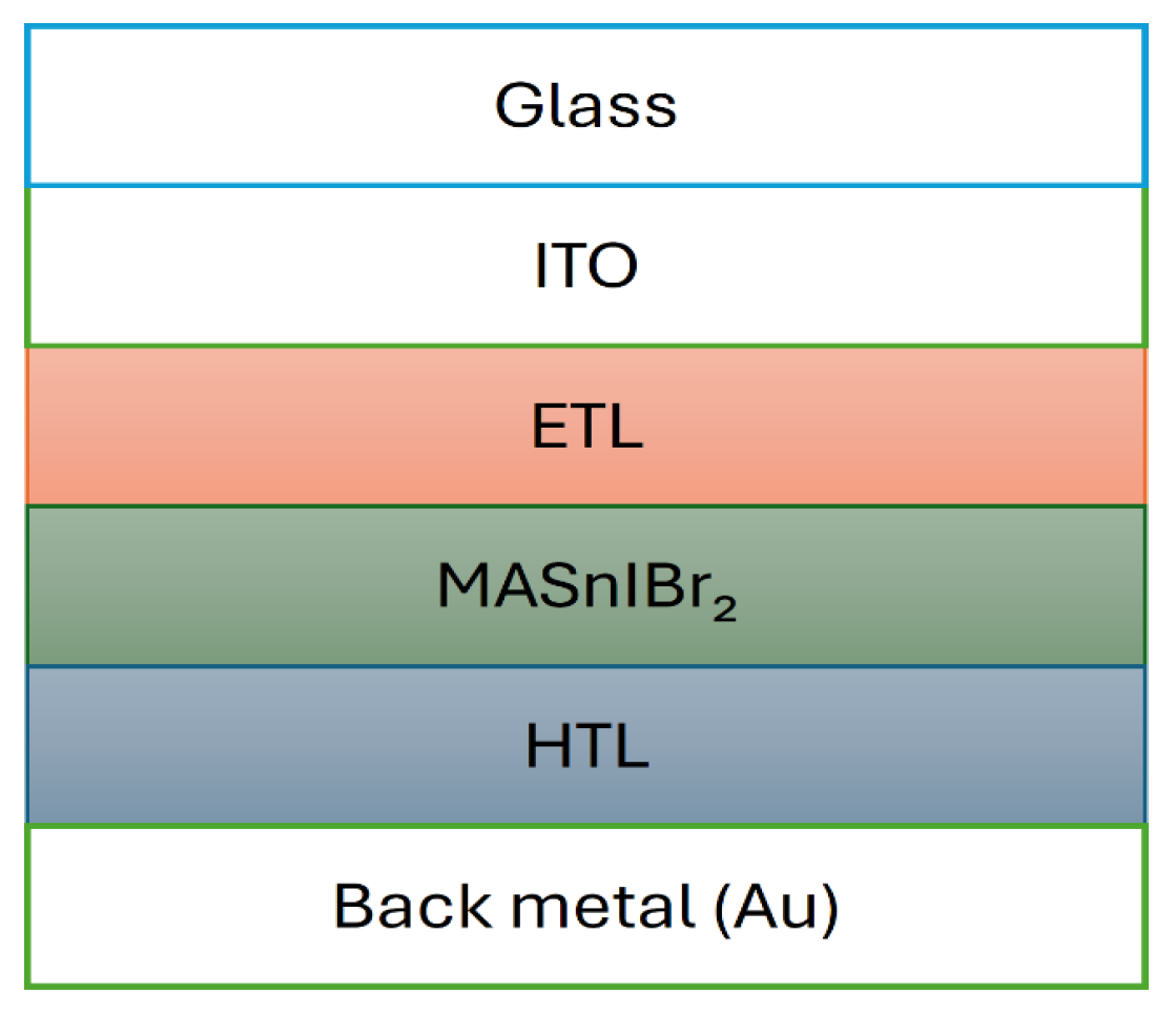
Figure 1. Structural configurations of the MASnIBr2-based perovskite solar cell.
Eng 06 00222 g001
Figure 2. Simulation process for optimal transport layer design in MASnIBr2 PSCs.
Eng 06 00222 g002
Figure 12. J–V performance of the initial and fully optimized MASnIBr2-based perovskite solar cell.
Eng 06 00222 g012
Figure 13. Energy band diagram of the optimized device structure, featuring MASnIBr2 perovskite positioned between the electron and hole transport layers.
Eng 06 00222 g013
Figure 14. Photovoltaic performance of the MASnIBr2-based solar cell as a function of the defect density of an MASnIBr2 absorber layer: (a) open-circuit voltage, (b) short-circuit current, (c) fill factor, and (d) power conversion efficiency.
Eng 06 00222 g014
Table 1. The electron transport layers and hole transport employ random simulation settings, while the active perovskite layers MASnIBr2 use parameters provided in the references [28,36,37,38,39].
Photovoltaic ParametersSymbolUnitHole Transport LayerElectron Transport LayerMASnIBr2
ThicknessThNm200200200
Energy Band GapEgeV231.75
Electron AffinityΧeV343.78
Dielectric Permittivity ϵ r 1898.2
Effective Density of States at Conduction BandNccm−32 × 10201 × 10191 × 1018
Effective Density of States at Valence BandNvcm−32 × 10201 × 10191 × 1018
Hole Thermal VelocityVecm/s1 × 1071 × 1071 × 107
Electron Thermal VelocityVhcm/s1 × 1071 × 1071 × 107
Electron Mobilityµecm−2/V·s4 × 10−42001.6
Hole Mobilityµhcm−2/V·s4 × 10−4801.6
Uniform Shallow Donor DopingNdcm−3-1 × 10161 × 1015
Uniform Shallow Acceptor DopingNacm−31 × 1016-1 × 10¹⁵
Defect DensityNtcm−31 × 10141 × 10141 × 1015
Table 2. Interface defect layer parameters [51,52].
InterfaceDefect
Type
Capture Cross-Section
Electrons–Holes (cm2)
Energetic
Distribution
Total Density (cm−3)
(Integrated over All Energies)
ETL/MASnIBr2Neutral1 × 10−17–1 × 10⁻¹⁸Single1 × 1010
MASnIBr2/HTLNeutral1 × 10−18–1 × 10⁻¹⁹Single1 × 1010
Table 3. The annual PCE improvements for MASnIxBr3-x (x = 0, 1, 3) perovskite solar cells along with the corresponding hole transport (HTL) and electron transport (ETL) layers used in each case.
YearAbsorber LayerHTL MaterialETL MaterialPCE (%)Ref.
2014MASnIBr2Spiro OMeTADTiO25.73[37]
2017MASnIBr2------3.7[36]
2019MASn(I0.33Br0.67)3Spiro OMeTADTiO23.2[38]
2020MASnIBr2PEDOT:PSSTiO216.07[67]
2022MASnIBr2Spiro OMeTADTiO211.74[39]
2022MASnI3Spiro OMeTADTiO29.44[68]
2024MASnI3CuSbS2C6020.7[69]
2025MASnBr3Cu2OWS222.71[70]
2025MASnIBr2Ideal HTLIdeal ETL20.42This work
Disclaimer/Publisher’s Note: The statements, opinions and data contained in all publications are solely those of the individual author(s) and contributor(s) and not of MDPI and/or the editor(s). MDPI and/or the editor(s) disclaim responsibility for any injury to people or property resulting from any ideas, methods, instructions or products referred to in the content.