Article

Power Optimization of Partially Shaded PV System Using Interleaved Boost Converter-Based Fuzzy Logic Method

by
Ali Abedaljabar Al-Samawi
1,2,*,
Abbas Swayeh Atiyah
1,2 and
Aws H. Al-Jrew
1,2
1
Department of Electronic and Communications Engineering, College of Engineering, Al-Muthanna University, Samawah 66001, Iraq
2
College of Engineering, Al Ayen University, Nasiriyah 64001, Iraq
*
Author to whom correspondence should be addressed.
Eng 2025, 6(8), 201; https://doi.org/10.3390/eng6080201
Submission received: 23 June 2025 / Revised: 26 July 2025 / Accepted: 6 August 2025 / Published: 13 August 2025
(This article belongs to the Section Electrical and Electronic Engineering)

Abstract

Partial shading condition (PSC) for photovoltaic (PV) arrays complicates the operation of PV systems at peak power due to the existence of multiple peak points on the power–voltage (P–V) characteristic curve. Identifying the global peak among multiple peaks presents challenges, as the system may become trapped at a local peak, potentially resulting in significant power loss. Power generation is reduced, and hot-spot issues might arise, which can cause shaded modules to fail, under the partly shaded case. In this paper, instead of focusing on local peaks, several effective, precise, and dependable maximum power point tracker (MPPT) systems monitor the global peak using a fuzzy logic controller. The suggested method can monitor the total of all PV array peaks using an interleaved boost converter DC/DC (IBC), not only the global peaks. A DC/DC class boost converter (CBC), the current gold standard for traditional control methods, is pitted against the suggested converter. Four PSC-PV systems employ three-phase inverters to connect their converters to the power grid.

1. Introduction

Solar energy, in contrast to fossil fuels such as coal, oil, and natural gas, remains inexhaustible and does not result in environmental contamination [1]. It is proficient in generating both heat and electrical energy using photovoltaic (PV) systems, which encounter issues with partial shade [2,3,4]. The partial shading condition (PSC) occurs when aging, damage, dust collection, temporary clouds, or nearby buildings and structures shade some photovoltaic (PV) cells or modules. After solar energy system installation, some circumstances may cause performance concerns. Shaded solar modules reduce output power and efficiency by 70% [5,6]. Hot-spot and thermal breakdown concerns may need bypass diodes, multilevel inverters, and a smart algorithm to safeguard PV modules [7,8,9,10,11]. PSC causes one global peak (GP) and multiple local peaks (LPs) in P-V. Recent research has monitored GPs rather than LPs using soft computing methodologies to maximize power extraction and efficiency. Traditional MPPT techniques like incremental conductance (IC), Hill Climbing (HC), and perturb and observe [12,13] are easy to use to detect the MPP under uniform conditions. These approaches vary in simplicity, design, cost, tracking speed, performance, efficiency, resilience, and accuracy. MPPT ant colony optimization (ACO) was evaluated, investigated, and compared to traditional MPPT perturb and observe methods and AI-based MPPT methods including ANN, fuzzy logic controllers, ANFIS, and FL-GA. It was compared to particle swarm optimization (PSO) and colony optimization [14]. Intelligence techniques like colony optimization and PSO performed well in accuracy, convergence speed, stability, and robustness [15]. Cooperation and competition enable IPSO [12,16,17], an upgraded particle swarm optimization technique, to track GPs precisely with minimum oscillation. Sending the optimal duty cycle to the DC-DC converter updates the particle’s velocity and position to monitor the GP [18]. AI methods like artificial neural networks (ANN), fuzzy logic controllers, (GA) genetic algorithms, and hybrid methods (for example, neuro-fuzzy systems or ANFIS with the GA) were shown to be accurate, fast, adaptable, energy-efficient, and easy to implement in [19]. Modern MPPT systems can monitor the global peak, while the PSCPV system can monitor all individual peaks better. This paper describes a novel method for reducing partial shadowing (PSC) impacts and maximizing power extraction from a photovoltaic solar power (PSC-PV) system using an interleaved boost converter (IBC) combined to numerous PV arrays. IBC improves PV system power quality, reliability, efficiency, and DC-link voltage stability. Several industrial industries utilize it for high voltage, current, and power. Additionally, IBC has several enticing features: (i) decreased input current fluctuations; (ii) minimized power switch and inductance burden, reducing passive component size; (iii) boosted voltage output. A dc/dc class converter is not recommended for PSPV systems; use an IBC since each PV module, string, or array in this IBC DC-DC converter has a different irradiance level, therefore a different output voltage. For DC-link voltage stability, a fixed IBC is recommended. Many evaluations in the literature [20,21,22,23,24,25,26,27,28,29] have shown that interleaved DC-DC converters are reliable, efficient, effective, electromagnetic emission-free, and ripple-free compared to a class boost converter (CBC) with continuous input power. Researchers in [20,24] showed how IBC may be integrated with PV to evaluate reliability, reduce ripple, and accelerate the transient response. However, unlike PSC, their study concentrated on PV systems running independently of PS to establish the IBC effectiveness in a constant-input power situation. Ref. [21] compared the DC-DC IBC topologies for energy renewable applications based on cost, reliability, flexibility, and efficiency [6]; however, Ref. [26] indicated that IBC might replace CBC for high-voltage applications.
In this article, an interleaved boost converter (IBC) in a PSC-based fuzzy MPPT approach may be the first to increase PSPV system performance. This method is economical and effective since it solves PS effects and becomes more power from each PV array branch than the PSPV system with a class boost converter (CBC). This research will examine a novel application that combines utility grid-connected multi-partially shaded solar arrays with interleaved boost converters. We compared the proposed IBC PSC-PV system to an existing CBC system that employed fuzzy controller logic based on maximum power point tracking to see how it varied in efficiency, power quality, and reliability. Thus, we provide the optimum IBC design that manages DC-link voltage and maximizes power extraction from the utility grid-linked PSPV system.
This system uses multiple PV arrays, which are integrated with an interleaved boost converter (IBC) that features its own MPPT control and separate DC-link for each PV system to solve the PSC problem. This structure aims to lower ripple current, regulate voltage DC-link, enhance power quality, and provide each PV array with its own MPPT control. This configuration, featuring a fuzzy MPPT, aims to achieve high output power and improve overall efficiency.

2. Materials and Methods

2.1. Modeling of Class and Interleaved Boost Converter

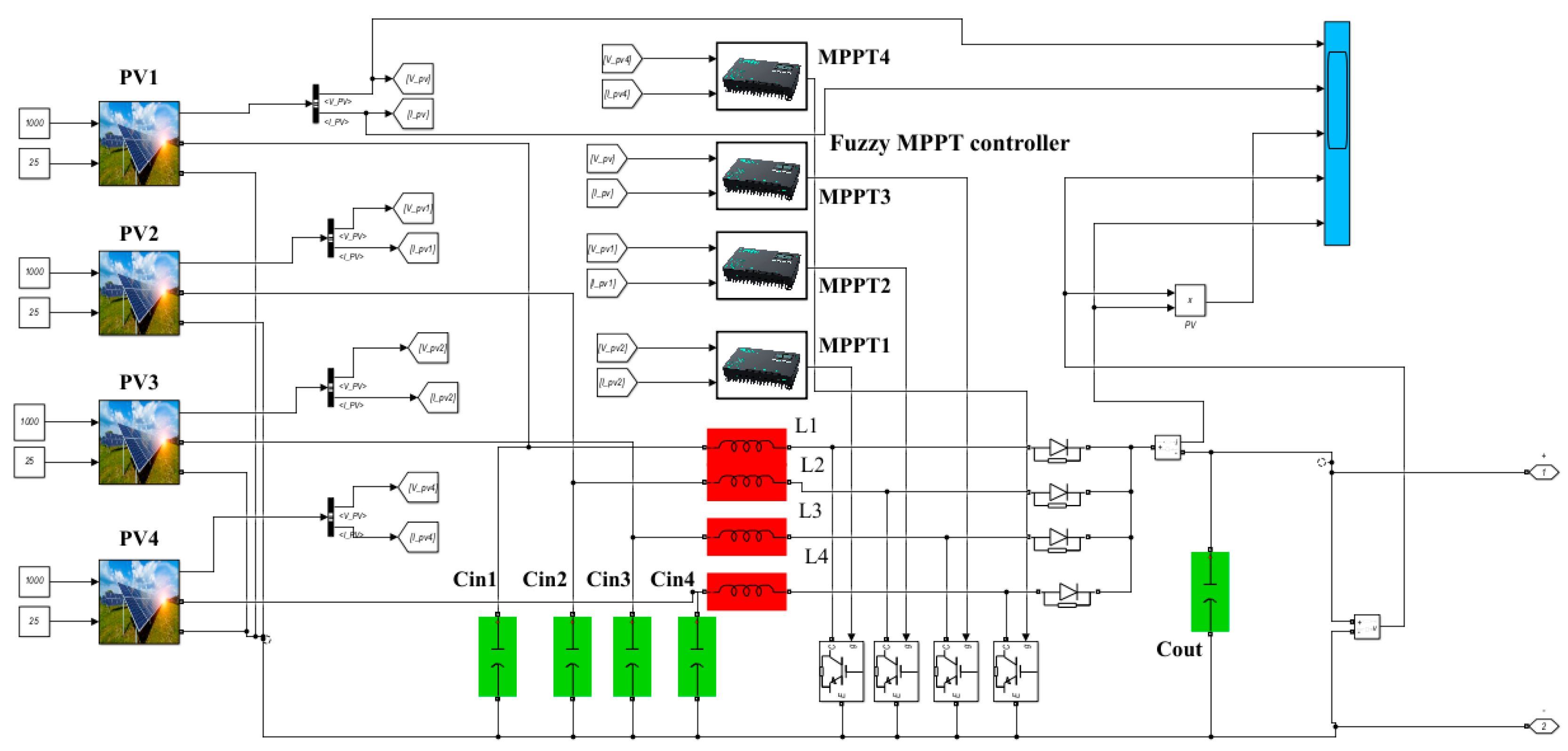
The solar array’s output voltage is not high enough to satisfy the needs of the load or inverter. In order to increase the voltage output of the system, a step-up DC/DC converter is integral to PV system applications and is included in the PV panel. The class DC/DC converter, as seen in Figure 1, only needs one MPPT controller.
The interleaved boost converter (IBC) has the added benefit of using a multi-MPPT controller as shown in Figure 2. In this research, a fuzzy MPPT controller is used in conjunction with a step-up interleaved DC/DC boost converter to obtain the best possible voltage output from the PV array. In order to maximize the power production of the solar panels, the duty cycle of the switch regulates the boost converter. Some designs for IBCs use continuous conduction mode as their foundation [30,31]. The input inductor current is not allowed to drop to zero in this mode. For the IBCs’ design, Table 1 shows the specifications of the PV panels and simulated system.
The design input inductor (L) and output capacitor (C dc) of the IBC are derived from the following formulas:
Vout = m * Vin
d = (Vout − Vin)/Vout = (m * Vin − Vin)/(m * Vin)
d = (m − 1)/m
Lb = (Vin * d)/(fs * ΔILb)
Cdc = (Vout * d)/(R * fs * ΔVout)
where the voltage gain is (m); (Vin) and (Vout), the input and output of the IBC; (d), the cycle duty; (fs), the switching frequency;   I L b , the inductor ripple current; and V o u t , the ripple value in the output voltage.

2.2. Analyzed PV Systems with CBC and IBC

2.2.1. PV Energy System Integrated CBC

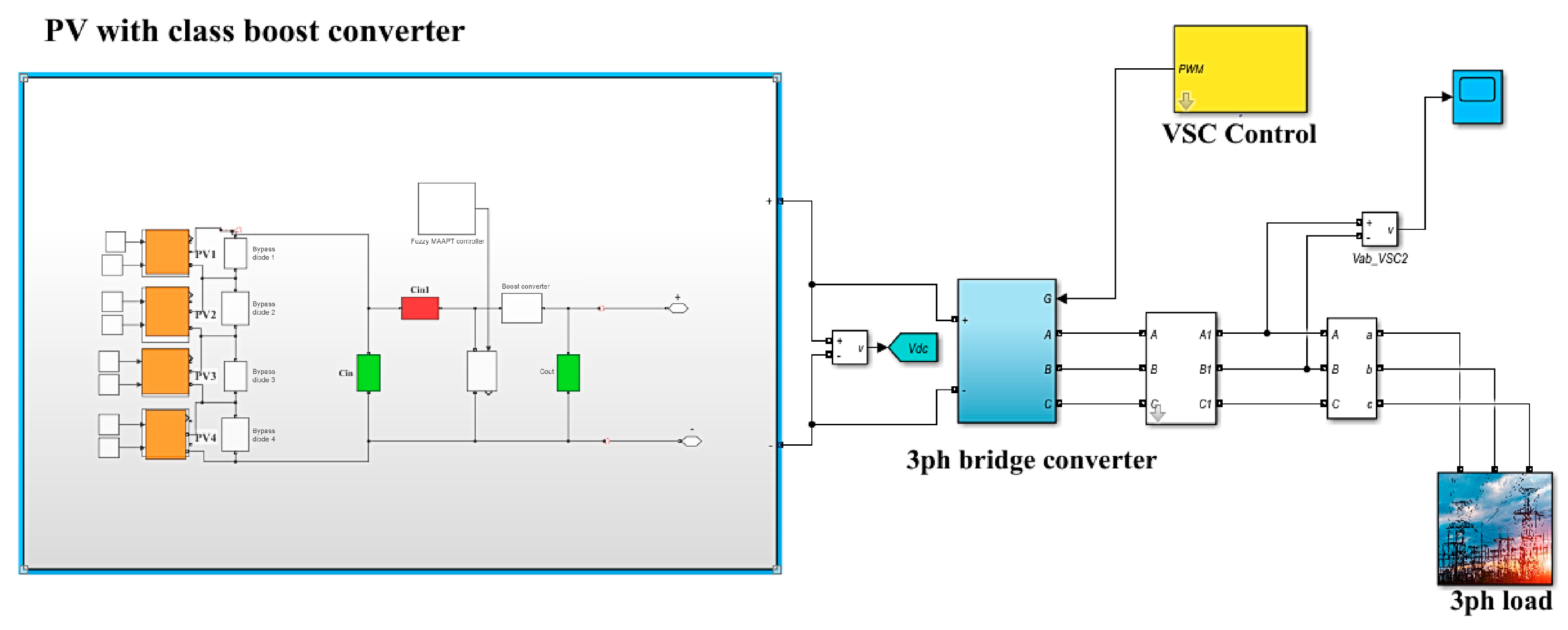
Figure 3 depicts a photovoltaic (PV) energy transformation system, with a four-phase inverter and class boost converter (CBC) linking the PV array to the utility grid. This figure shows a four-PV group-type panel A10 Green technology A10J-S72-175, connected between each of the two PV groups with a bypass diode, integrated with a class boost converter with one MPPT controller to solve the PSC problem. This bypass diode is used to safeguard the photovoltaic module against hot-spot phenomena and potential thermal breakdowns (refer to Figure 1). A substantial reverse voltage will be generated across any modules or shaded cells without protection from bypass diodes. As a result, both the power output and the efficiency of the photovoltaic system diminish owing to heightened power losses.
The solar array receives its inputs from the sun’s irradiance (W/m2) and the temperature of the cells (°C). To symbolize the PSCs, three PV arrays are used, each with its own unique radiation. Multiple peaks, namely three, are produced by PSCs, and the GP occurs at various points along the P-V curve.

2.2.2. PV Energy System Integrating IBC

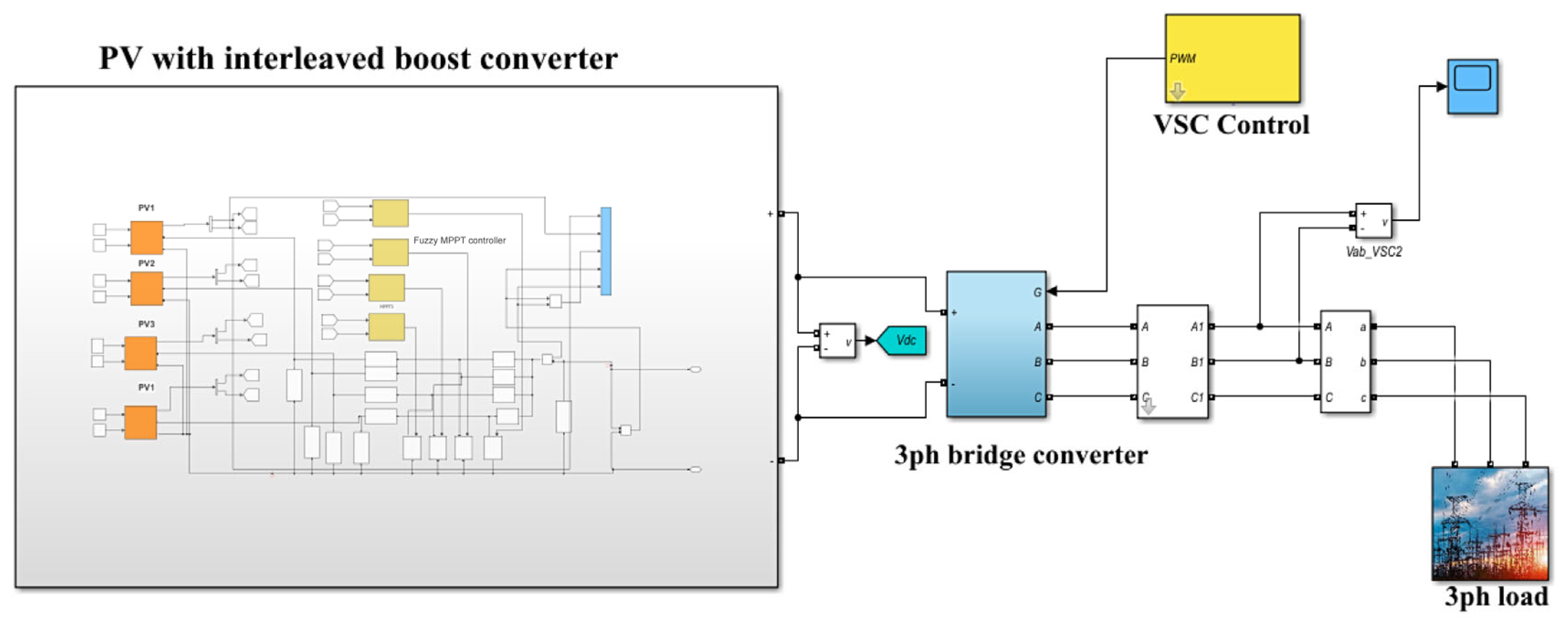
A multi-PV array integrated IBC converter-based fuzzy MPPT controller, as shown in Figure 2. Figure 4 shows a multi-PV array that is part of a system that is linked to the utility grid using an IBC and a PWM-VSC. The objective behind integrating intelligent battery controllers with multiple photovoltaic systems is to lower ripple current, enhance power quality, manage the voltage DC-link, and allow each PV array to be independently controlled using MPPT, all of which will lead to a higher output produced power and more efficiency. Regarding the PS effects associated with the system’s maximum power and efficiency, this suggested PV system also fixes and reduces them.
A distinct MPP tracker keeps tabs on each PV array’s performance by monitoring the duty cycle of its own boost converter. Figure 4 shows that each IBC branch has its own distinct duty cycle, and that each PV array uses its own MPP tracker fuzzy controllers to monitor its own MPP. So, as will be seen in the section on simulation results, the suggested multi-PV integrated with an IBC operates at its maximum power point, and the aggregated peak power supplied by this partial shading PV system is higher than the global power recorded by the prior PSC-PV system with a CBC.

2.3. Fuzzy Controller Design

2.3.1. Fuzzy Control

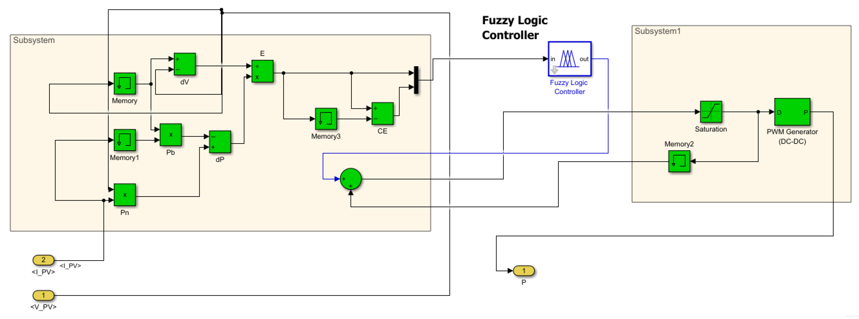
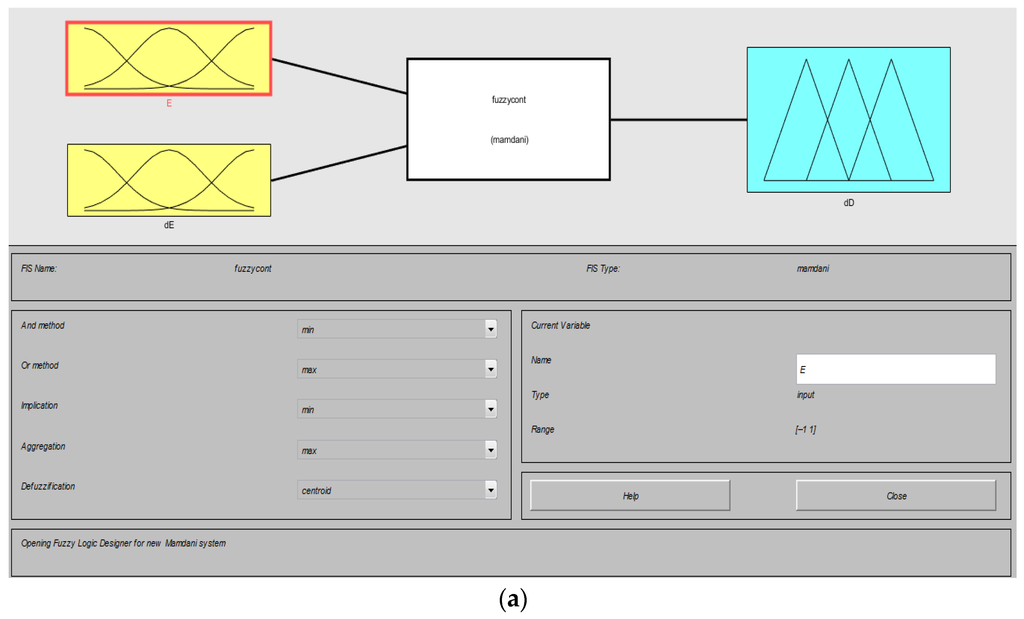
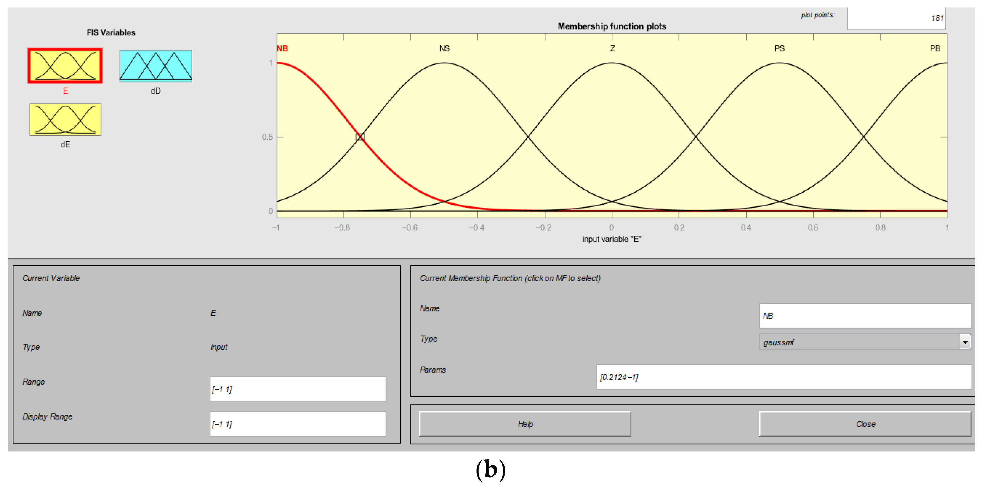
Fuzzy logic control is a technique that enables the development of nonlinear controllers utilizing heuristic information derived from the expertise of an expert [32,33,34,35,36,37,38,39,40,41,42]. The input signals are processed by the fuzzification block, which assigns them an imprecise value. This set of rules is predicated on the process’s understanding and enables the regulation of the variables’ linguistic descriptions. The inference mechanism interprets the data according to their membership functions and rules. The defuzzification block transforms fuzzy data produced by the inference method into precise, fuzzy non-information advantageous for process management For designing a fuzzy controller, use the input current and voltage PV as shown in Figure 5. Result in a new duty cycle (dD) after using a fuzzy controller by changing the duty cycle (E&DE) according to the changing voltage as shown in Figure 6.

2.3.2. Structure of Fuzzy Logic

(a)
Two inputs: Error (E) and change in error (DE); range: [−1, 1]; Gaussian membership functions.
(b)
Control fuzzy logic: A total of 25 fuzzy rules are applied using Mamdani inference, as shown Table 2. Each rule connects two inputs and one output, as shown in the table, using the Inference Engine method (AND Method (min), OR Method (max)) and then converting the results into an actual control output signal using the centroid method. This method computes the centroid of the fuzzy form.
(c)
One output (dD): Range: [−1, 1]; the correction signal controls for changes in duty cycle (dD) using centroid-based defuzzification over Gaussian double-output membership functions.

2.3.3. Summary of Flow Chat Implementation Steps for Fuzzy Logic Controller

Step 1.
Input Variables (E, dE):
The error (E) and change in error (dE) as inputs to the fuzzy logic controller.
Step 2.
Fuzzification:
The crisp input values (E and dE) are converted into fuzzy values using membership functions (MFs). Here, you use Gaussian MFs to represent the fuzziness of the input data.
Step 3.
Rule Evaluation:
The fuzzy rules (“If E is NB and dE is NB, then dD is NB”) are applied to evaluate the fuzzy outputs. You have 25 rules to determine the fuzzy control action.
Step 4.
Aggregation:
The outputs of all the active rules are combined to create an aggregated fuzzy output. This step combines the contributions of each rule based on the fuzzified inputs.
Step 5.
Defuzzification:
The centroid technique is used to transform the fuzzy output back into a crisp value. This method calculates the weighted average of the fuzzy set to produce a crisp output.
Step 6.
Control Signal (dD):
The crisp output (dD) is used to adjust the system. This is the control action that your FLC generates. Fuzzy logic offers faster response, adapts to nonlinearity, is noise-resistant, and reduces oscillation at MPP through comparisons with incremental conductance and perturb and observe methods. Table 3 shows the advantages and disadvantages of these three different methods of MPPT.
Table 3. Advantages and disadvantages of three different methods of MPPT [43,44,45,46,47,48].
Method of MPPTAdvantagesDisadvantages
Fuzzy controller
  • Fast response with fast irradiance and temperature variations.
  • Adaptive and responsive to nonlinear and unpredictable systems.
  • Lower oscillation related to the maximum power point.
  • Resilient to noise, does not need exact measurements.
  • Design-independent, operates without an integrated PV model.
  • Higher intricacy in design and execution.
  • Demands adjustment of membership functions and rule basis.
  • The quality of the fuzzy logic design has significant influence on its effectiveness.
Incremental Conductance
  • Precise monitoring of the MPP only in constant state.
  • Implementation is easy, utilizing fundamental mathematical formulas.
  • Appropriate for embedded systems and devices with limited resources.
  • High sensitivity to noise in measurements of current and voltage.
  • High oscillations about MPP.
  • Slow responses to abrupt variations in irradiance or temperature.
  • Needs precise, real-time current and voltage readings.
  • Incorrectly selecting the step size might cause instability.
Perturb and Observe
  • A straightforward algorithm—clear and easy to apply.
  • Minimal computational expense, appropriate for low-power systems.
  • Near MPP oscillations, particularly in constant state.
  • Slow tracking under rapidly fluctuating circumstances (irradiance/temperature).
  • Less accurate than fuzzy or IC algorithms.

2.4. Control Strategy of Voltage Source Converter

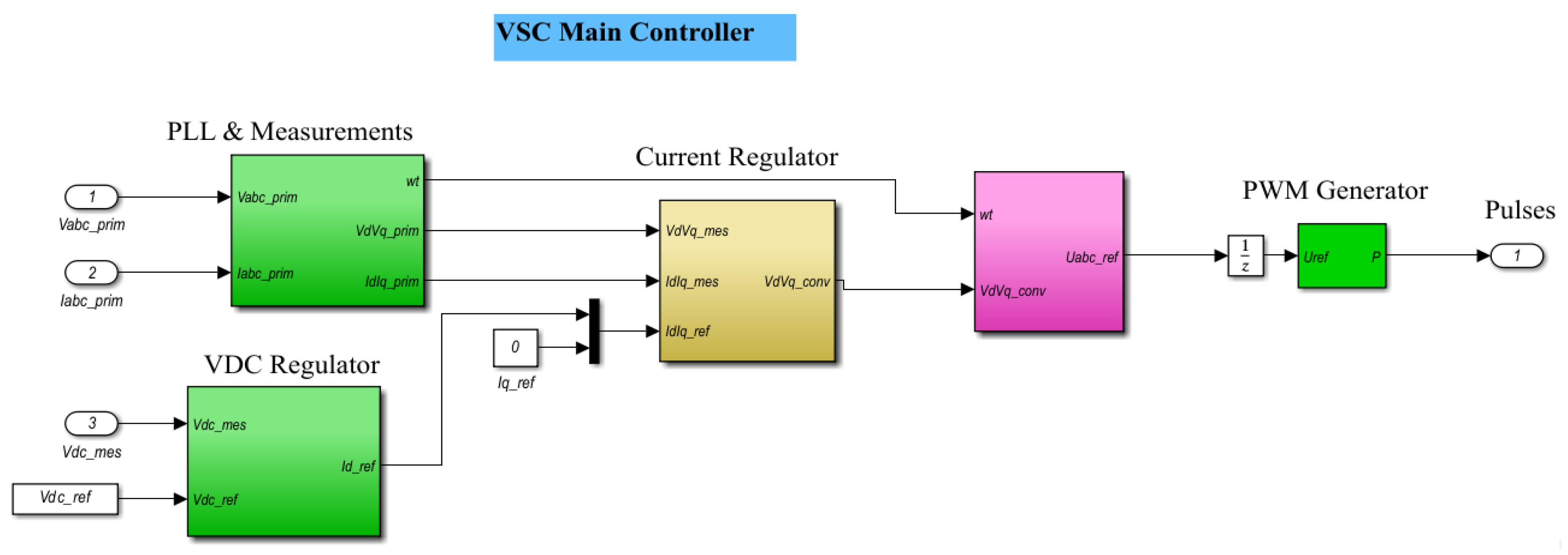
Inverter topology operates as a converter, specifically transforming direct current (DC) to alternating current (AC) during the process of transferring electrical power to the load. The control system is a voltage source converter (VSC) for grid-connected applications, as shown in Figure 7. The control method initiates with the PLL (phase-locked loop) block, which transforms voltage and current into dq components and provides the angular frequency. The VDC regulator maintains voltage DC bus by producing current reference on d-axis. The reference, in conjunction with a constant q-axis current reference, is transmitted to the current regulator. This component compares the received references with the observed dq currents and produces the required dq voltage references. The references are transformed back into voltages and transmitted to the PWM generator, which creates switching pulses to control the converter. The system ensures accurate power management and stable DC voltage output.

3. Results

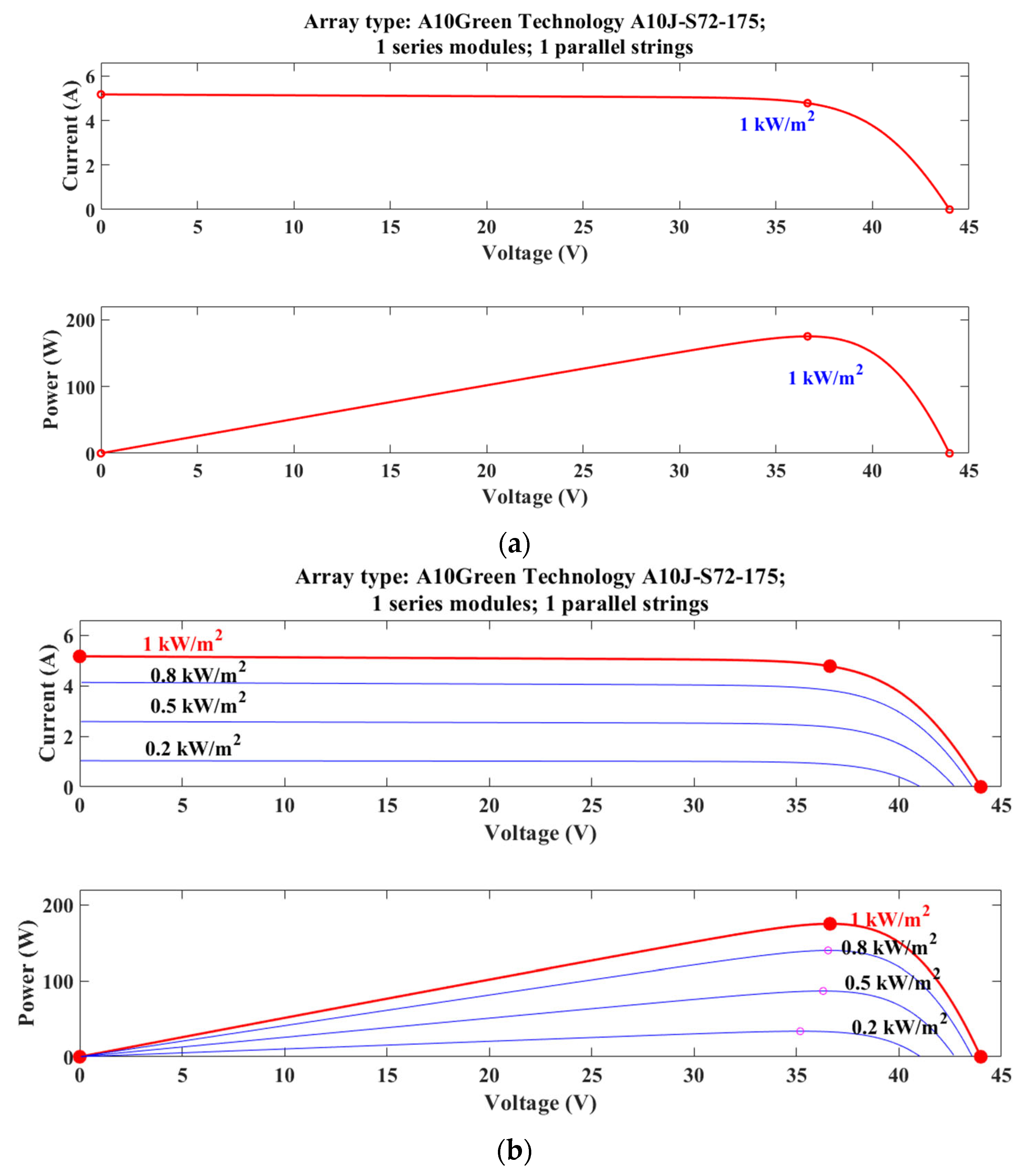
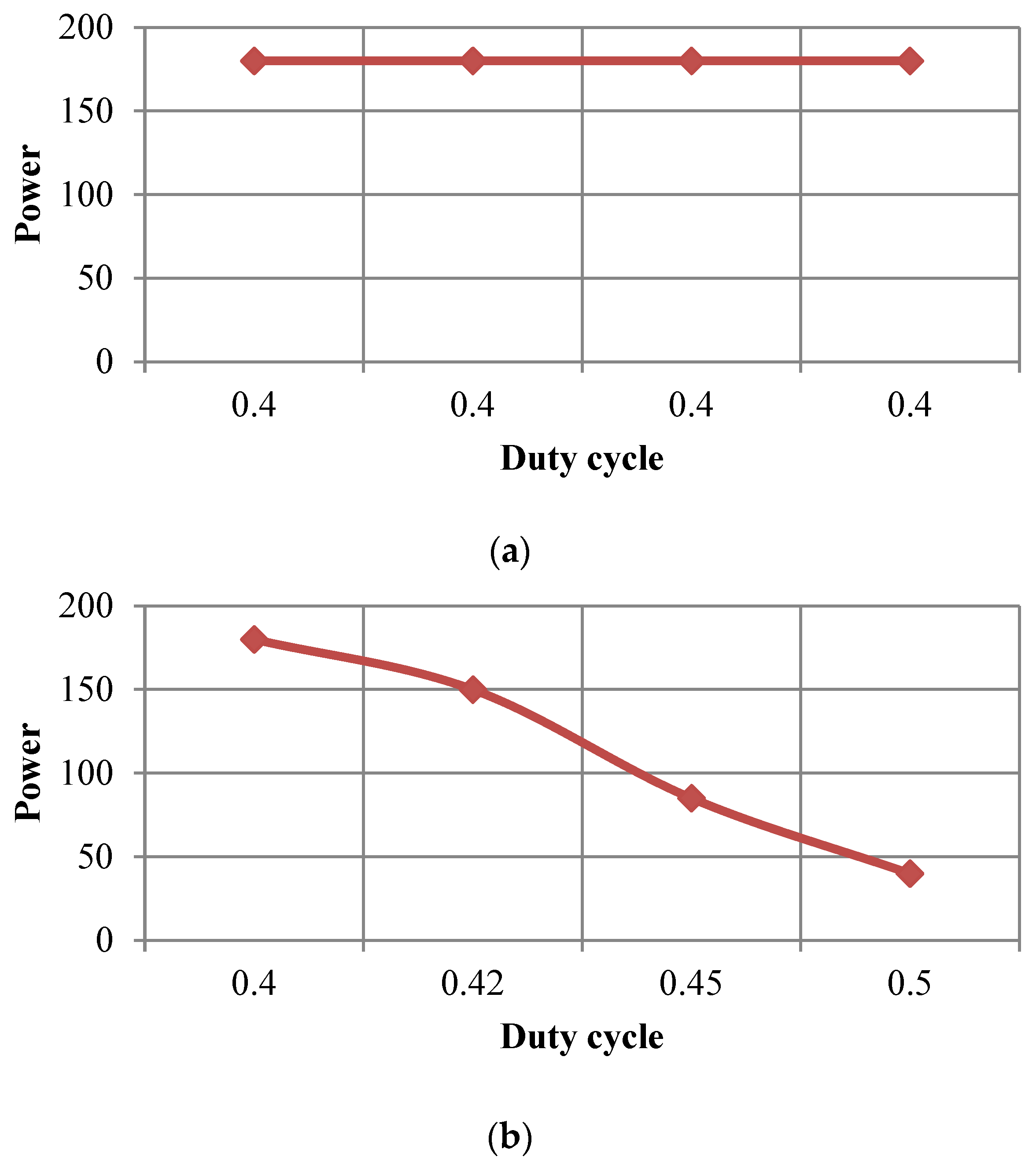
The performance of the suggested fuzzy MPPT interleaved boost converter was compared to that of the class boost converter under normal weather and partial shading using Matlab/Simulink software R2023A. The PV system configuration shown in Figure 8 is a converter-integrated array of four modules. Figure 8a presents the current and voltage power for each PV group under normal weather (constant irradiation) with a stable duty cycle, as shown in Figure 9a. Figure 8b presents the current, voltage, and power for each PV group under partial shading (variable irradiation) with a change in duty cycle, as shown in Figure 9b.

3.1. Performance of Interleaved Boost Converter (IBC)-Based Fuzzy Logic MPPT

3.1.1. Performance of IBC for Constant-Level Irradiance (CLI)

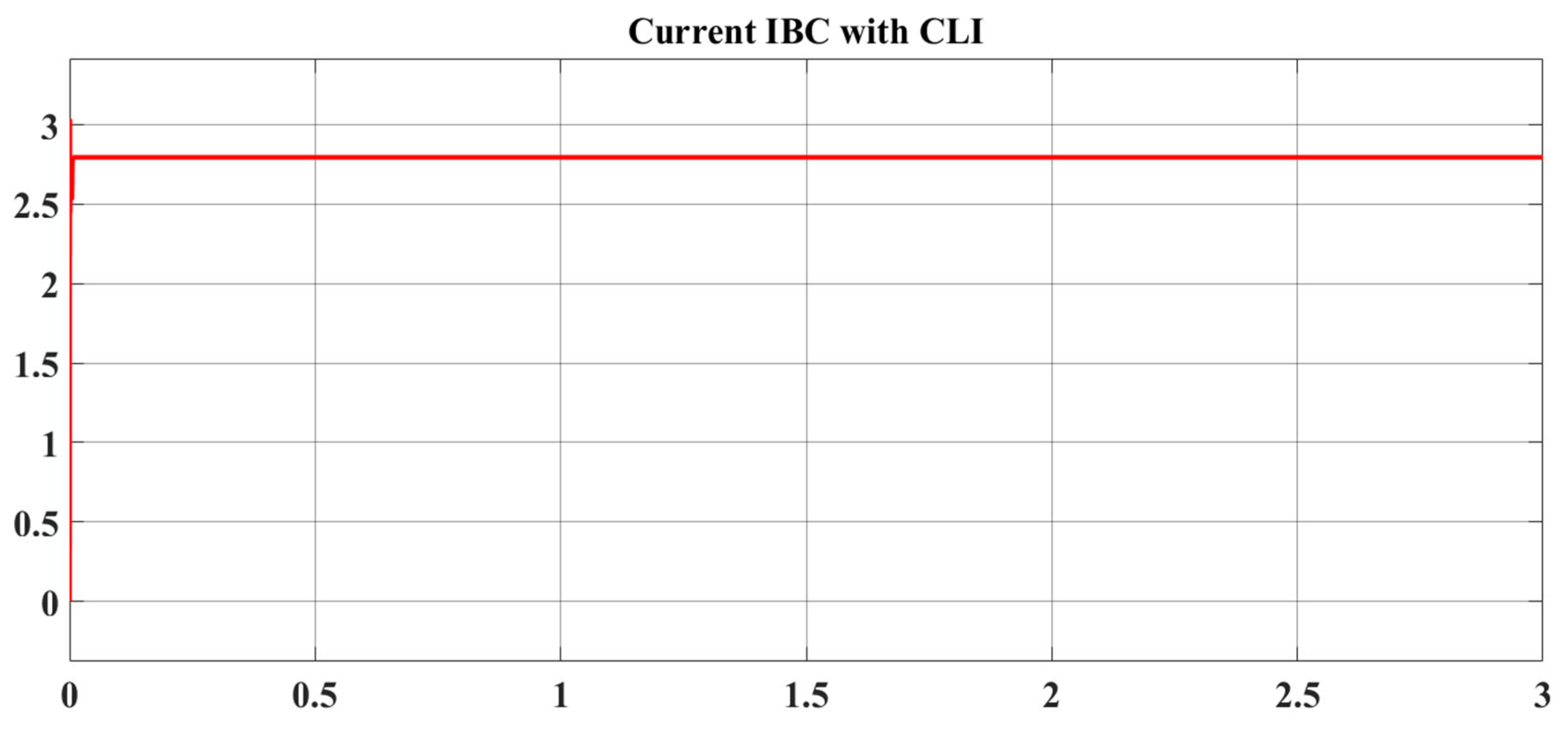
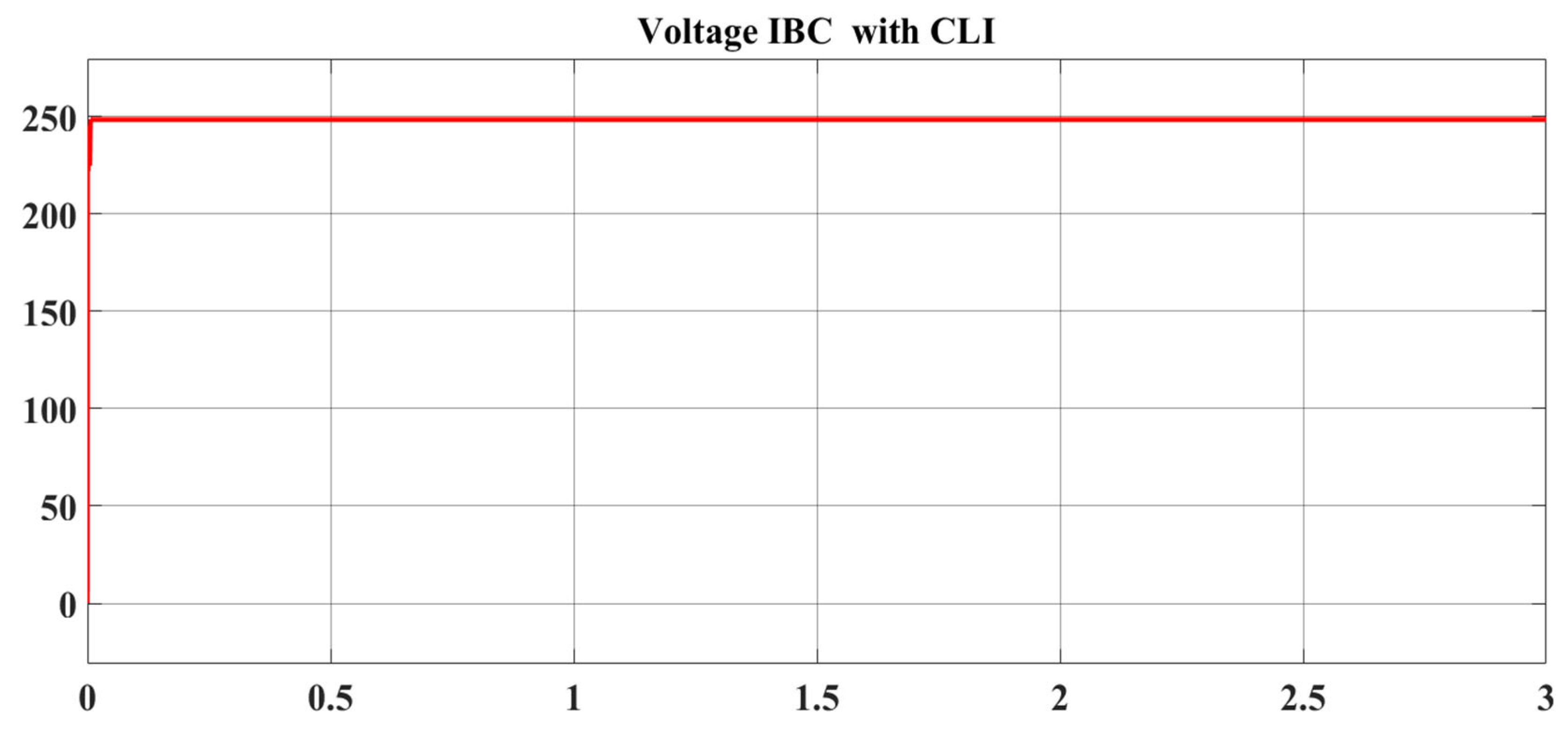
The efficacy of the proposed four-PV string boost converter using a fuzzy MPPT controller was evaluated under constant irradiance and temperature conditions, namely S = 1000 W/m2 and T = 25 °C. The whole array’s maximum power (P_PV = 740 W), consisting of four arrays, each rated at 185 W, was achieved under stable weather circumstances. The MPPT eliminated the steady-state oscillation around the MPP, hence enhancing PV efficiency. Figure 10, Figure 11 and Figure 12 illustrate the output DC voltage, DC, and DC power of the proposed IBC-based fuzzy MPPT under stable weather circumstances.
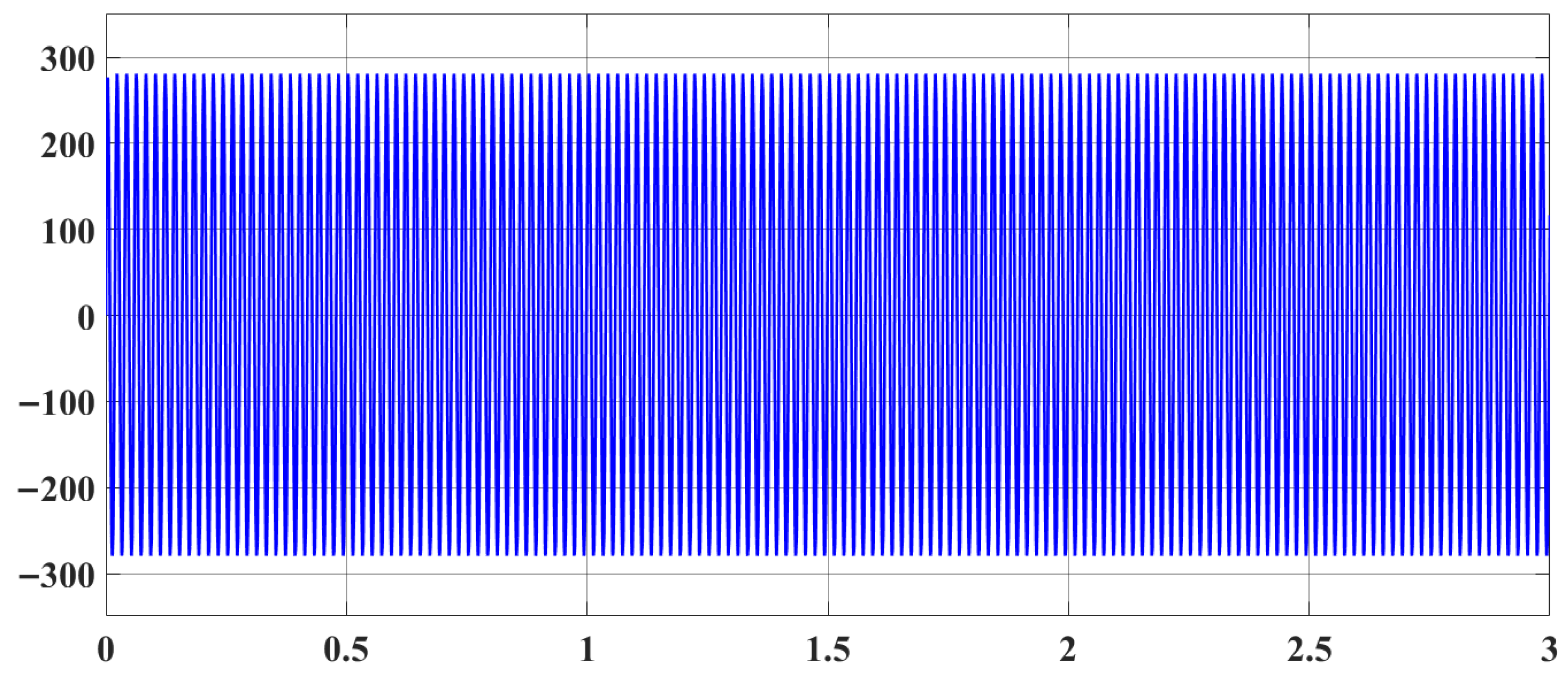
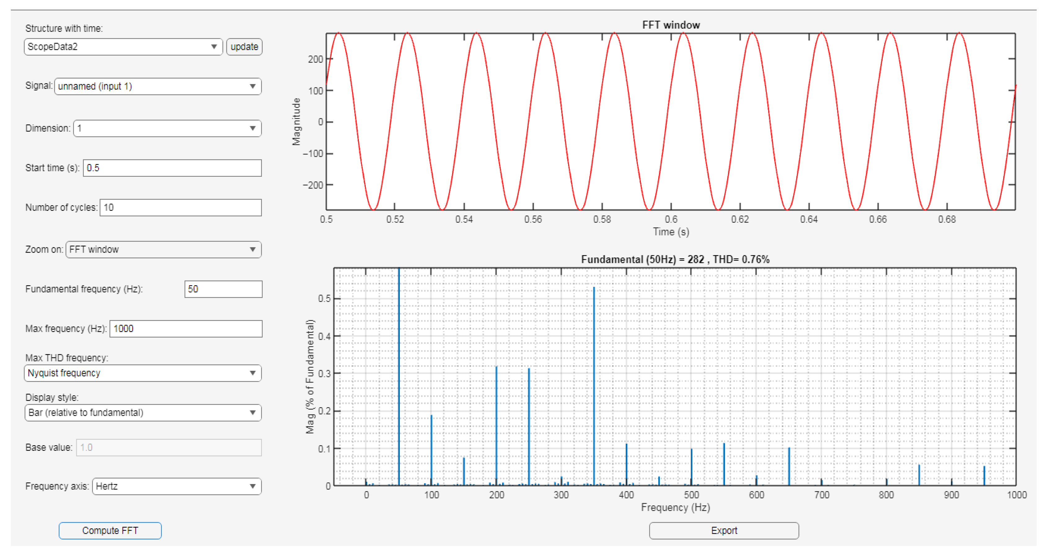
The voltage inverter output, following LCL filtering (L = 40 mH, C = 50 mF), given to the load, is shown in Figure 13. THD in the output voltage is 0.76% at a high frequency of 10 kHz, as seen in Figure 14. A commendable total harmonic distortion (THD) rating of 0.76% was observed, according to the IEEE standard limit of ≤5%.

3.1.2. Performance of IBC Under Partial Shading Conditions (PSCs)

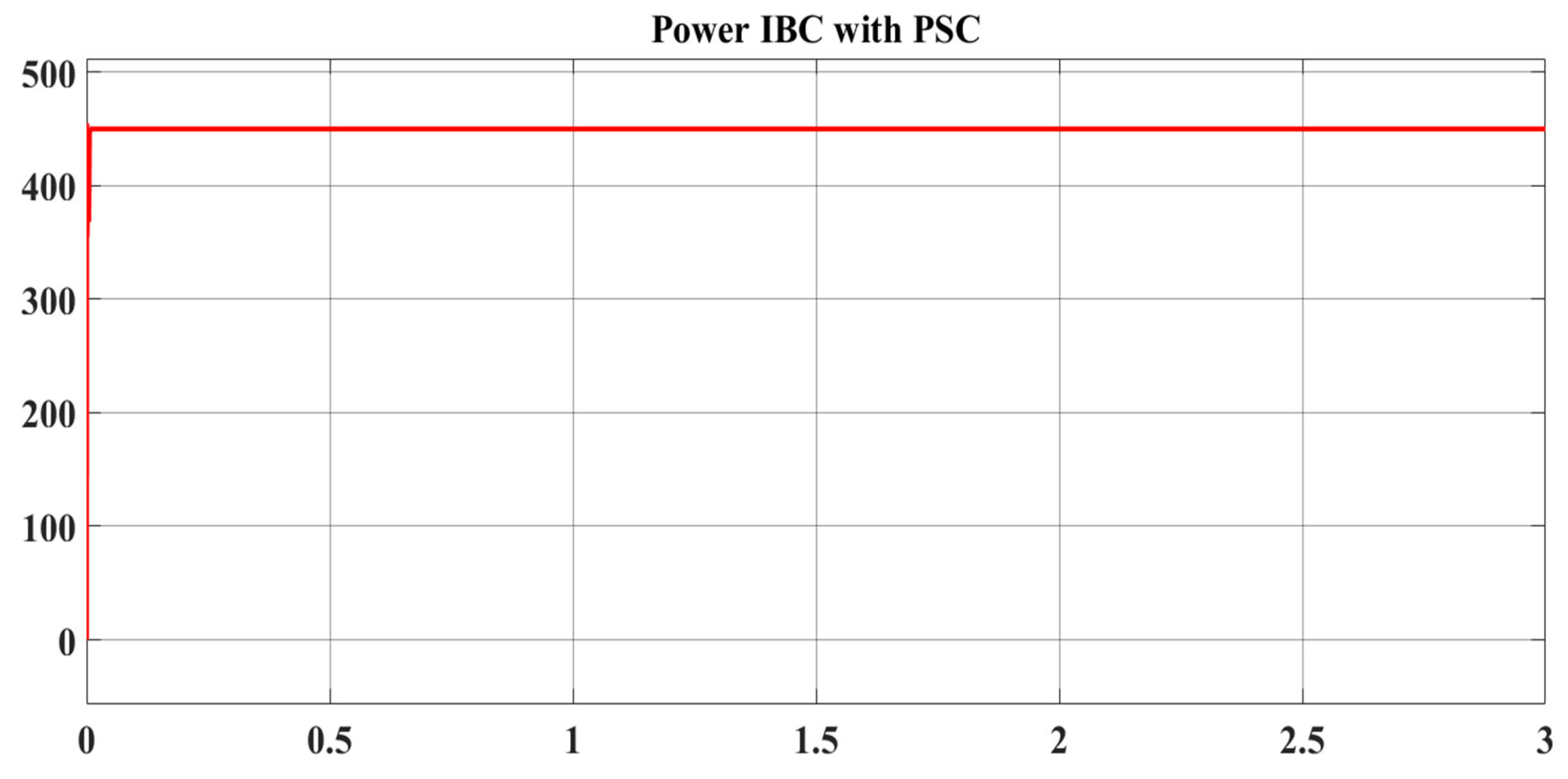
This part evaluates the performance of the suggested IBC-based MPPT fuzzy logic under rapid variations in irradiance. The irradiance levels are adjusted to PV1 at 1000 W/m2, PV2 at 800 W/m2, PV3 at 1000 W/m2, and PV4 at 200 W/m2, as seen in Figure 8. Figure 15, Figure 16 and Figure 17 depict the output DC voltage, DC, and DC power of the proposed IBC-based fuzzy MPPT under variable irradiance conditions. The voltage inverter output, after LCL filtering and load provision, is shown in Figure 18. The THD observed in the output voltage is 0.93% at a high frequency of 10 kHz, as seen in Figure 19. Figure 18 shows that, in comparison to the converter CBC, this IBC demonstrated better quality for partial shading.

3.2. Performance Class Boost Converter (CBC)-Based Fuzzy Logic MPPT

3.2.1. Performance of CBC with Constant Irradiance Level (CLI)

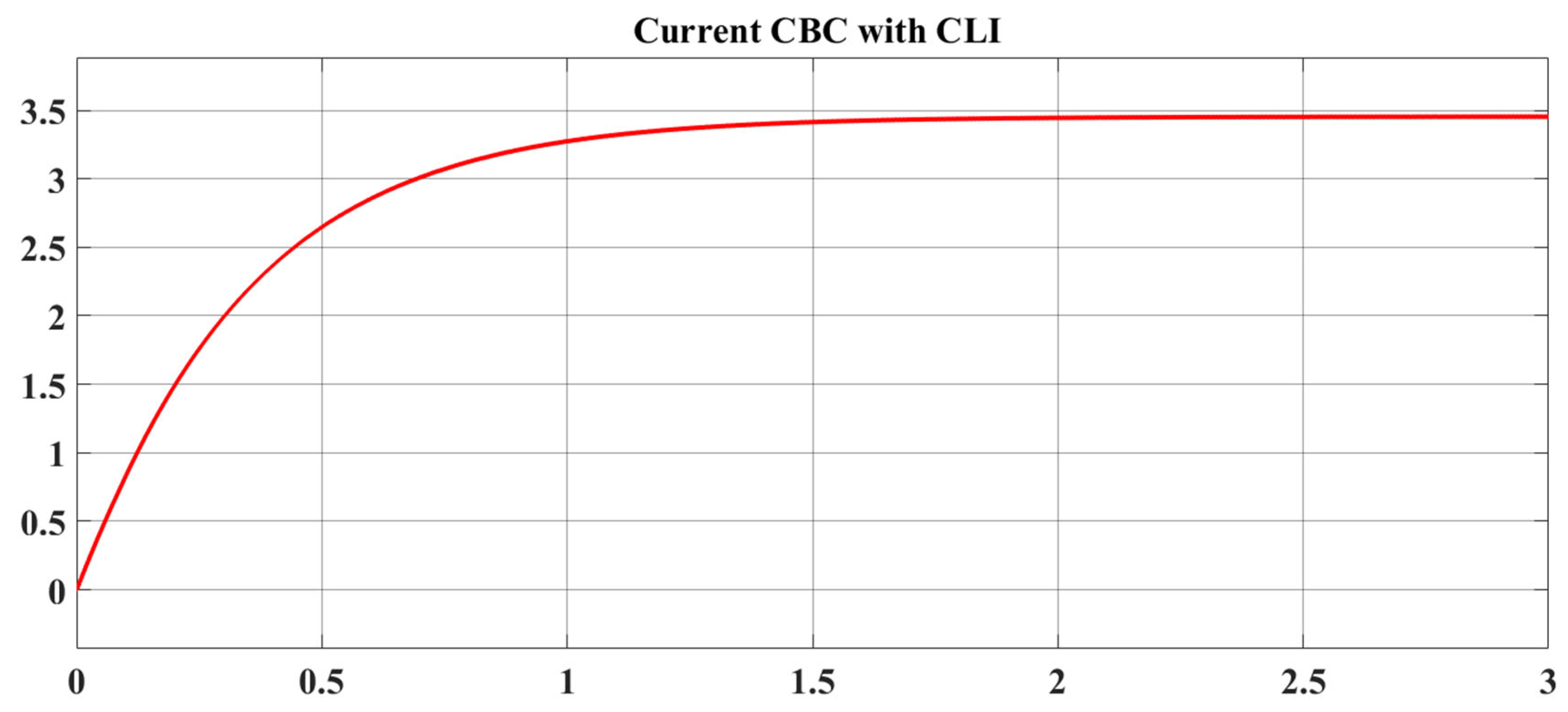
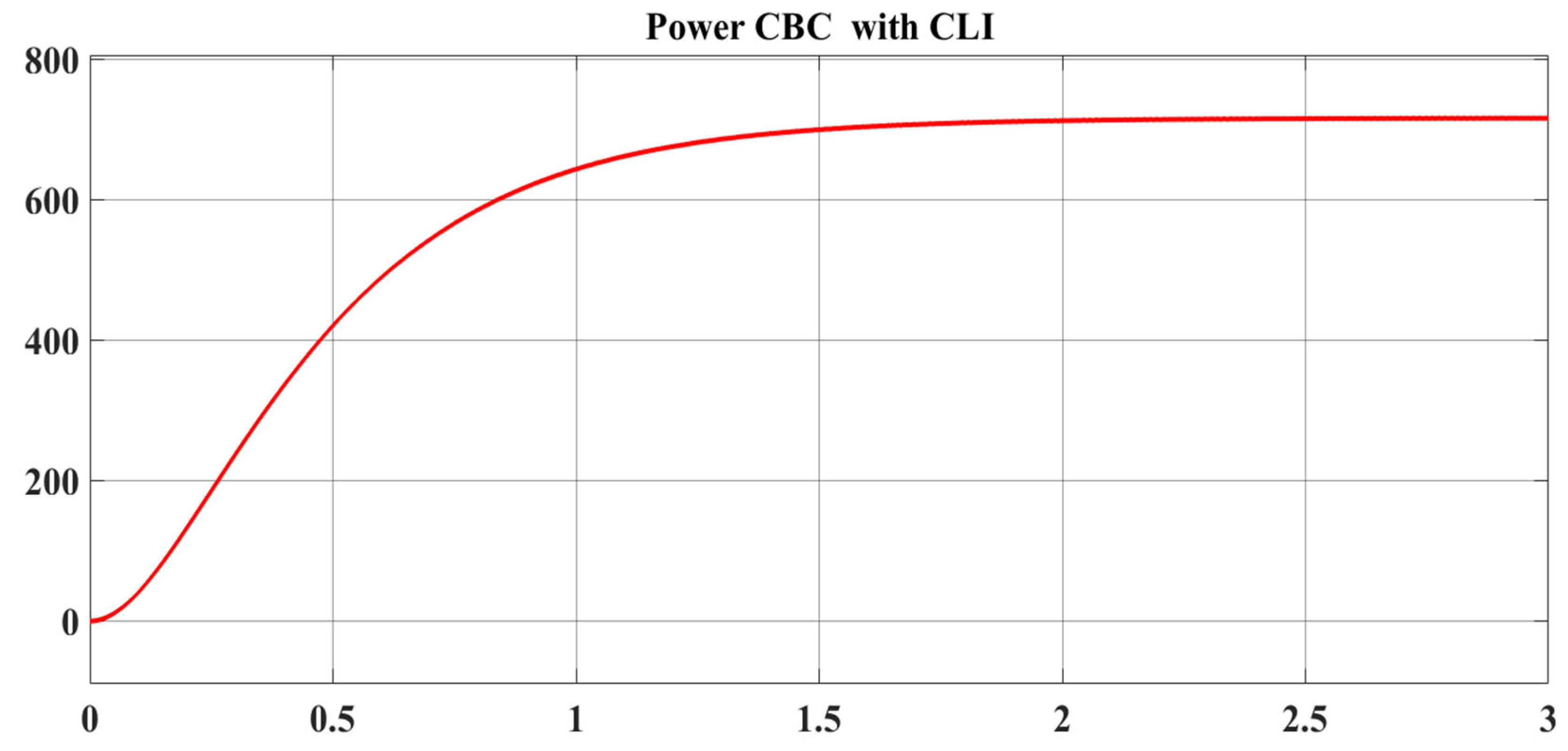
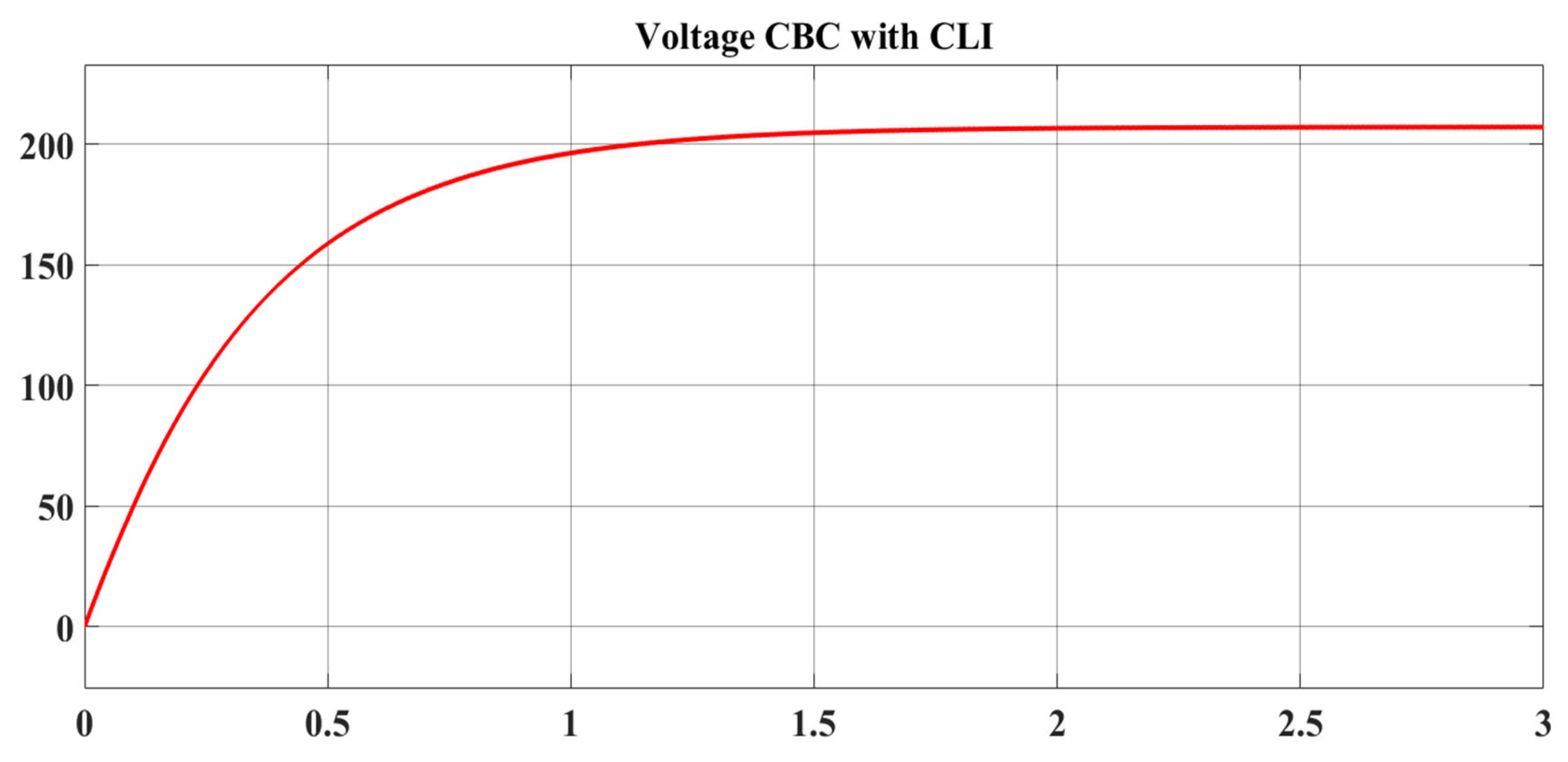
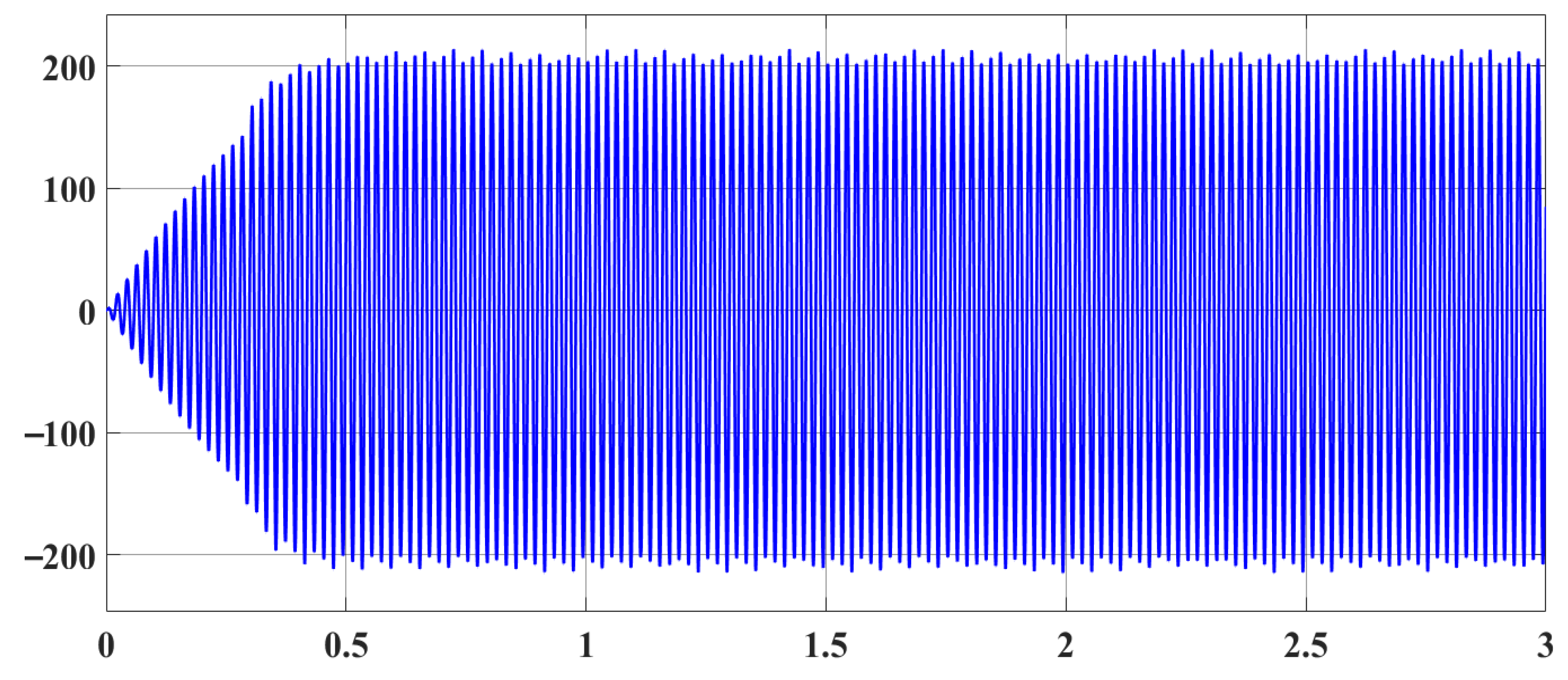
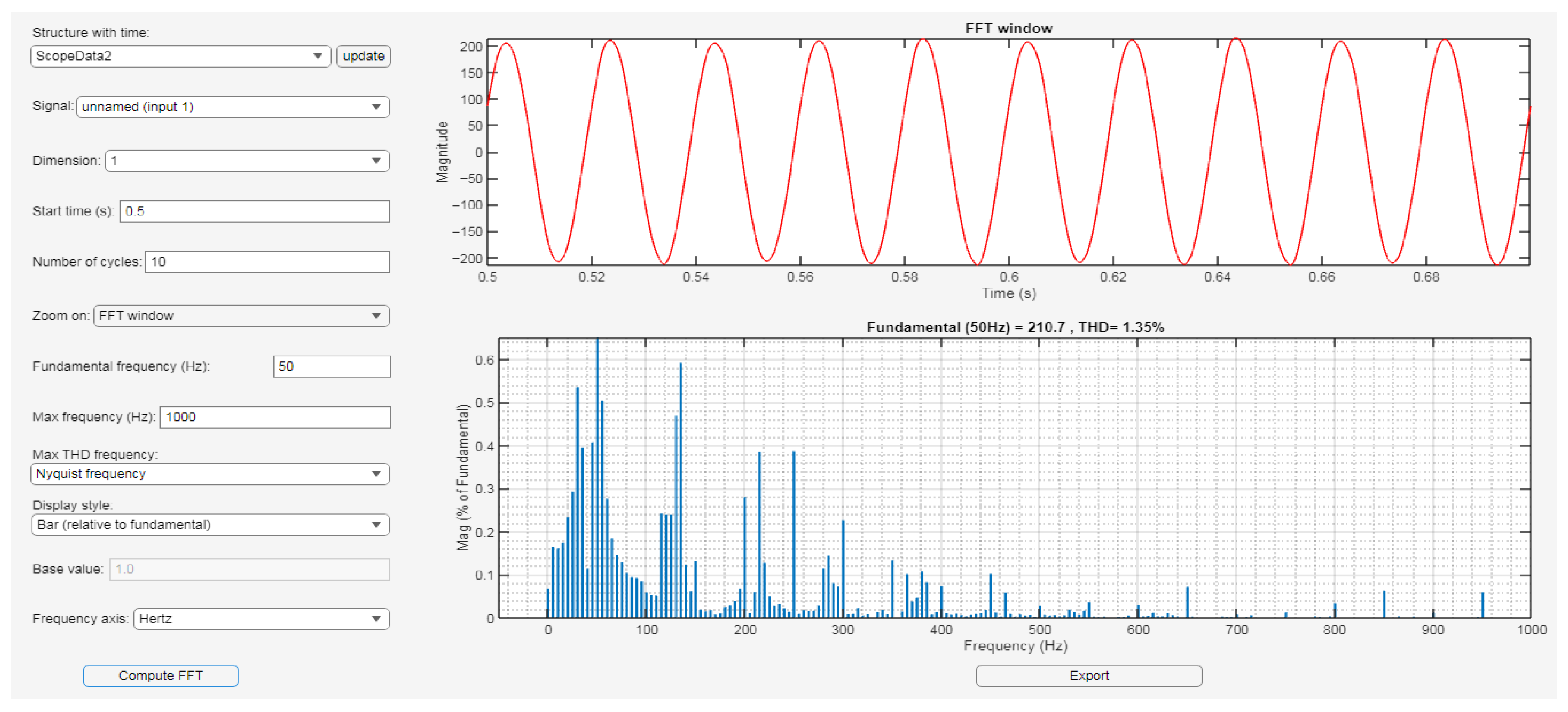
The efficacy of the proposed four-boost converter-based fuzzy MPPT controller was evaluated under constant irradiance and temperature conditions, namely S = 1000 W/m2 and T = 25 °C. Figure 20, Figure 21 and Figure 22 illustrate the output DC voltage, DC, and DC power of the proposed IBC-based fuzzy MPPT under constant weather circumstances. The filtered voltage from the inverter, given to the load, is shown in Figure 23. The THD in the output voltage is 1.35% at a high frequency of 10 kHz, as seen in Figure 24.

3.2.2. Performance of CBC Under Partial Shading Conditions

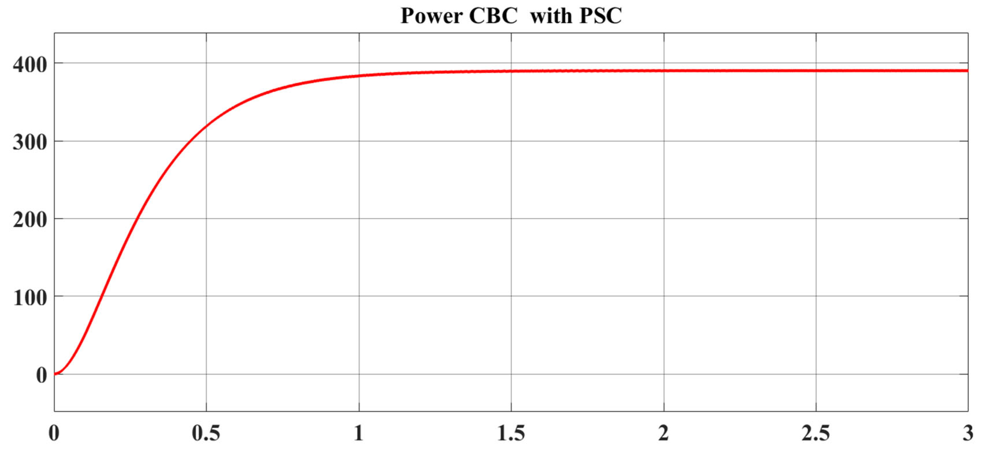
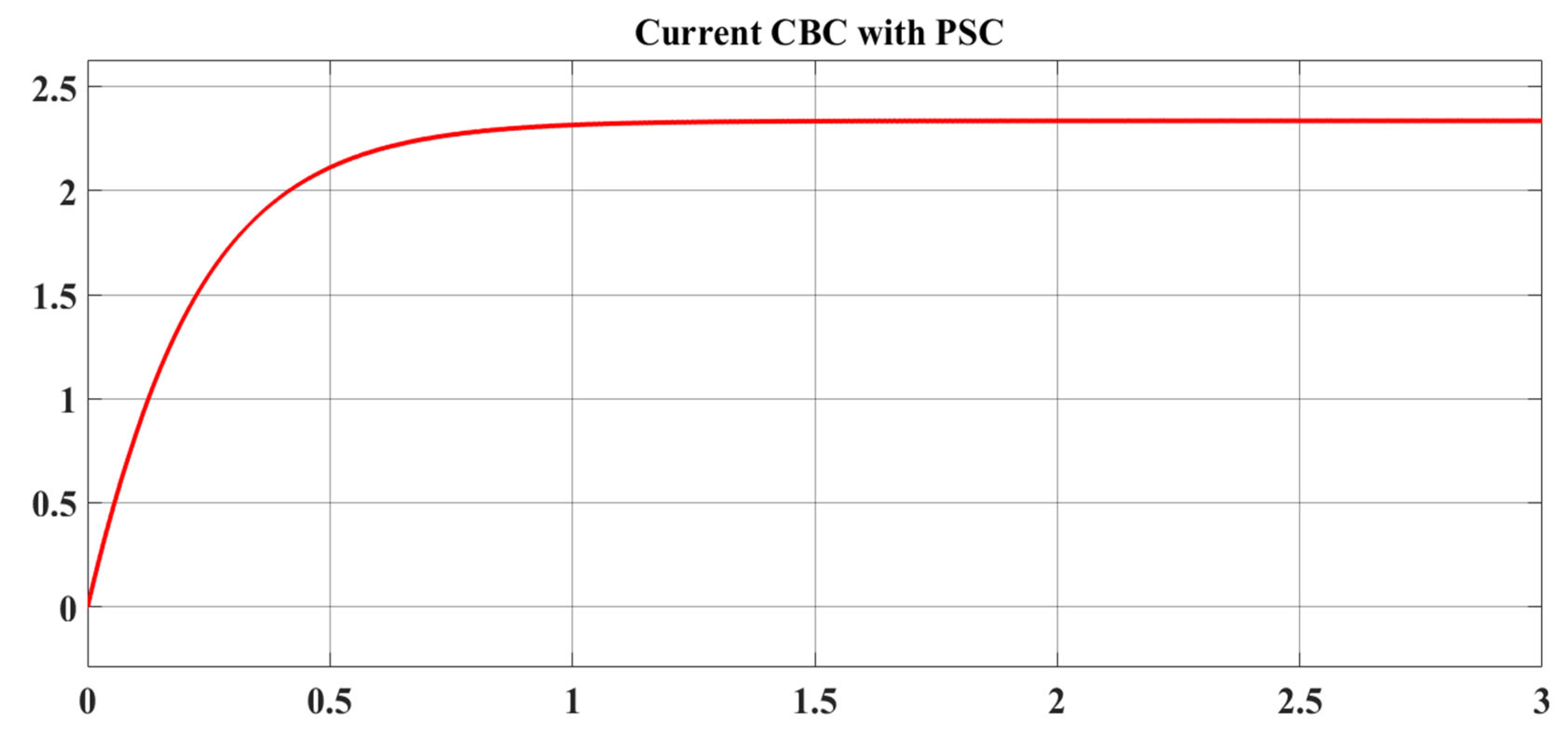
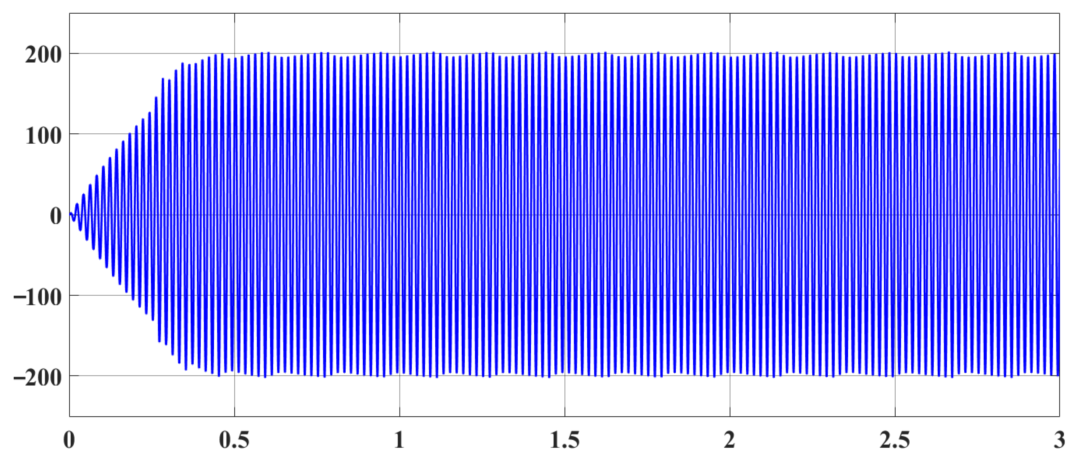
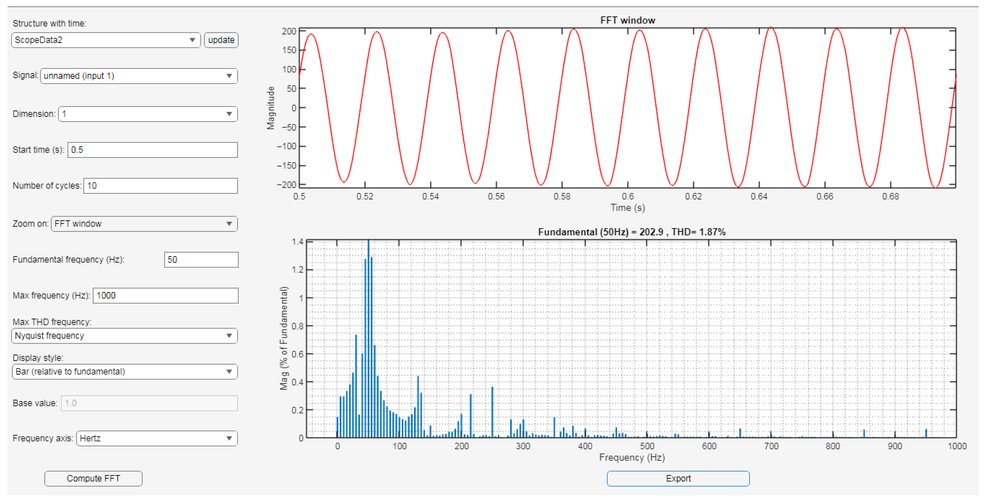
In this part, the performance of the proposed IBC was evaluated under rapid variations in irradiance, in comparison to the CBC. As illustrated in Figure 8, the irradiance levels were varied as follows: PV1 (1000 W/m2), PV2 (800 W/m2), PV3 (1000 W/m2), and PV4 (200 W/m2). Figure 25, Figure 26 and Figure 27 depict the output DC voltage, DC, and DC power of the proposed IBC-based fuzzy MPPT under constant weather conditions. The output current and voltage of the inverter, post-filtering through the LCL, delivered to the load, are presented in Figure 28. The THD in the output voltage is 1.87% at a high frequency of 10 kHz, as seen in Figure 29.

4. Discussion

In this section, Table 4 provides a summary of the output voltage, current, power, and THD for the IBC converter under PSCs, compared with those of the CBC converter. The efficiency of 99.72% under normal conditions and 97.82% under partial shading for the IBC is greater than that of the CBC converter. In addition, there is less THD because each independent MPPT controller PV panel string integrates separate DC links, while the opposite converter, CBC that has one DC link input, one capacitor, and one MPPT controller. therefore, high-power-quality AC voltage for the IBC, as shown in Figure 13, Figure 18, Figure 23 and Figure 28.

5. Comparative Analysis with Comparable Studies

This Table 5 contrasts various IBC designs for diverse energy systems. The choice of MPPT technology, converter type, and design parameters depends on the specific application, whether it involves large-scale PV systems, fuel cell integration, or systems operating under partial shading. The proposed IBC systems demonstrate enhanced performance, mostly due to the integration with fuzzy logic MPPT independent of a separate dc-link for each PV, which enhances dynamic responsiveness and maintains high efficiency under partial shade conditions. Compared to in many previous studies, these systems offer improved harmonic performance, increased reliability, and broader applicability, making them suitable for photovoltaic systems.

6. Conclusions

This paper proposes a fuzzy logic controller MPPT method with an interleaved boost converter PV system and grid topology. The performance analysis and comparison involved two proposed fuzzy logic controller MPPT methods with the following PV system and dc/dc boost configurations: interleaved (IBC) and class (CBC) converters. This comparison between partial shading and normal conditions was performed by modeling the circuitry in MATLAB/SIMULINK. The partial shading conditions (PSC) significantly decrease the power output of photovoltaic (PV) systems in comparison to optimal generation conditions. An independent MPPT controller with PV panel string on separate DC links addresses the issue of partial shading conditions (PSC) and safeguards the PV system from damage caused by the hot-spot effect for IBCs. In addition, to track the maximum power through the MPPT, the use of effective soft computing methods makes sure that the maximum power from the partial shading PV system compared with a CBC. The primary objective of this study is to suggest a solution that is both effective and efficient through the use of an IBC. The results demonstrate the effectiveness of IBCs in managing PSC using a fuzzy MPPT controller, primarily through its role in extracting the maximum power from the entire PV system under PSCs. Furthermore, it improves the stability of voltage DC-links, as well as the quality, reliability, efficiency, and flexibility of the power system. The multisystem PV IBC configuration is determined to be effective for managing PSCs and is applicable for large-scale PV applications. Furthermore, it provides an excellent option for mitigating the impacts of PSCs while outperforming alternative PV system designs in terms of output power and complexity.

Author Contributions

A.A.A.-S.: writing—original draft preparation; A.S.A. and A.H.A.-J.: writing—review and editing. All authors have read and agreed to the published version of the manuscript.

Funding

This research received no external funding.

Institutional Review Board Statement

Not applicable.

Informed Consent Statement

Not applicable.

Data Availability Statement

The original contributions presented in this study are included in the article. Further inquiries can be directed to the corresponding author.

Conflicts of Interest

The authors declare no conflicts of interest.

Abbreviations

The following abbreviations are used in this manuscript:
PVPhotovoltaic
MPPTMaximum power point tracker
CBCClass boost converter
IBCInterleaved boost converter
CLIConstant level irradiance (constant weather conditions)
PSCsPartial shading conditions
THDTotal harmonic distortion

References

  1. Rajendran, G.; Raute, R.; Caruana, C. A Comprehensive Review of Solar PV Integration with Smart-Grids: Challenges, Standards, and Grid Codes. Energies 2025, 18, 2221. [Google Scholar] [CrossRef]
  2. Endiz, M.S.; Gökkuş, G.; Coşgun, A.E.; Demir, H. A Review of Traditional and Advanced MPPT Approaches for PV Systems Under Uniformly Insolation and Partially Shaded Conditions. Appl. Sci. 2025, 15, 1031. [Google Scholar] [CrossRef]
  3. Eltamaly, A.M. An improved cuckoo search algorithm for maximum power point tracking of photovoltaic systems under partial shading conditions. Energies 2021, 14, 953. [Google Scholar] [CrossRef]
  4. Al-Samawi, A.A.; Alkhafaji, A.S.; Atiyah, A.S.; Trabelsi, H. Review Mitigation Methods of Partial Shading Condition for PV System. In Proceedings of the 2024 21st International Multi-Conference on Systems, Signals & Devices (SSD), Erbil, Iraq, 22–25 April 2024; pp. 401–410. [Google Scholar] [CrossRef]
  5. Al-Samawi, A.A.; Trabelsi, H. New Nine-Level Cascade Multilevel Inverter with a Minimum Number of Switches for PV Systems. Energies 2022, 15, 5857. [Google Scholar] [CrossRef]
  6. Farh, H.M.H.; Othman, M.F.; Eltamaly, A.M.; Al-Saud, M.S. Maximum power extraction from a partially shaded PV system using an interleaved boost converter. Energies 2018, 11, 2543. [Google Scholar] [CrossRef]
  7. Maghami, M.R.; Hizam, H.; Gomes, C.; Radzi, M.A.; Rezadad, M.I.; Hajighorbani, S. Power loss due to soiling on solar panel: A review. Renew. Sustain. Energy Rev. 2016, 59, 1307–1316. [Google Scholar] [CrossRef]
  8. Al-Samawi, A.A.; Trabelsi, H. Power Quality Enhancement of PV System Based on Modified Three-Phase Cascaded Multilevel Inverter. In Proceedings of the 2022 19th International Multi-Conference on Systems, Signals & Devices (SSD), Setif, Algeria, 6–10 May 2022; pp. 339–346. [Google Scholar] [CrossRef]
  9. Alves, T.; N. Torres, J.P.; Marques Lameirinhas, R.A.; F. Fernandes, C.A. Different techniques to mitigate partial shading in photovoltaic panels. Energies 2021, 14, 3863. [Google Scholar] [CrossRef]
  10. Duong, M.Q.; Sava, G.N.; Ionescu, G.; Necula, H.; Leva, S.; Mussetta, M. Optimal bypass diode configuration for PV arrays under shading influence. In Proceedings of the 2017 IEEE International Conference on Environment and Electrical Engineering and 2017 IEEE Industrial and Commercial Power Systems Europe (EEEIC/I&CPS Europe), Milan, Italy, 6–9 June 2017; pp. 1–5. [Google Scholar] [CrossRef]
  11. Al-Samawi, A.A.; Trabelsi, H. Seven-level Cascade Multilevel Inverter based Minimum Switches for Photovoltaic applications. In Proceedings of the 2023 20th International Multi-Conference on Systems, Signals & Devices (SSD), Mahdia, Tunisia, 20–23 February 2023; pp. 957–966. [Google Scholar] [CrossRef]
  12. Ishaque, K.; Salam, Z.; Lauss, G. The performance of perturb and observe and incremental conductance maximum power point tracking method under dynamic weather conditions. Appl. Energy 2014, 119, 228–236. [Google Scholar] [CrossRef]
  13. Ahmed, J.; Salam, Z. An improved perturb and observe (P&O) maximum power point tracking (MPPT) algorithm for higher efficiency. Appl. Energy 2015, 150, 97–108. [Google Scholar] [CrossRef]
  14. Xia, K.; Li, Y.; Zhu, B. Improved photovoltaic MPPT algorithm based on ant colony optimization and fuzzy logic under conditions of partial shading. IEEE Access 2024, 12, 44817–44825. [Google Scholar] [CrossRef]
  15. Titri, S.; Larbes, C.; Toumi, K.Y.; Benatchba, K. A new MPPT controller based on the Ant colony optimization algorithm for Photovoltaic systems under partial shading conditions. Appl. Soft Comput. 2017, 58, 465–479. [Google Scholar] [CrossRef]
  16. Ishaque, K.; Salam, Z.; Amjad, M.; Mekhilef, S. An improved particle swarm optimization (PSO)–based MPPT for PV with reduced steady-state oscillation. IEEE Trans. Power Electron. 2012, 27, 3627–3638. [Google Scholar] [CrossRef]
  17. Saady, I.; Majout, B.; Bossoufi, B.; Karim, M.; Elkafazi, I.; Merzouk, S.; Almalki, M.M.; Alghamdi, T.A.H.; Skruch, P.; Zhilenkov, A. Improving photovoltaic water pumping system performance with PSO-based MPPT and PSO-based direct torque control using real-time simulation. Sci. Rep. 2025, 15, 16127. [Google Scholar] [CrossRef] [PubMed]
  18. Miyatake, M.; Toriumi, F.; Endo, T.; Fujii, N. A novel maximum power point tracker controlling several converters connected to photovoltaic arrays with particle swarm optimization technique. In Proceedings of the 2007 European Conference on Power Electronics and Applications, Aalborg, Denmark, 2–5 September 2007; pp. 1–10. [Google Scholar] [CrossRef]
  19. Danyali, S.; Babaeifard, M.; Shirkhani, M.; Azizi, A.; Tavoosi, J.; Dadvand, Z. A new neuro-fuzzy controller based maximum power point tracking for a partially shaded grid-connected photovoltaic system. Heliyon 2024, 10, e36747. [Google Scholar] [CrossRef] [PubMed]
  20. Ramaprabha, R.; Balaji, K.; Raj, S.; Logeshwaran, V. Comparison of interleaved boost converter configurations for solar photovoltaic system interface. J. Eng. Res. 2013, 10, 87–98. [Google Scholar] [CrossRef]
  21. Rehman, Z.; Al-Bahadly, I.; Mukhopadhyay, S. Multiinput DC–DC converters in renewable energy applications. An overview. Renew. Sustain. Energy Rev. 2015, 41, 521–539. [Google Scholar] [CrossRef]
  22. Khosroshahi, A.; Abapour, M.; Sabahi, M. Reliability evaluation of conventional and interleaved DC–DC boost converters. IEEE Trans. Power Electron. 2015, 30, 5821–5828. [Google Scholar] [CrossRef]
  23. Prasanth, P.; Seyezhai, R. Investigation of four phase interleaved boost converter under open loop andclosed loop control schemes for battery charging applications. Int. J. Adv. Materi. Sci. Eng. 2016, 5, 2201–2311. [Google Scholar] [CrossRef]
  24. Aghdam, F.H.; Hagh, M.T.; Abapour, M. Reliability evaluation of two-stage interleaved boost converter interfacing PV panels based on mode of use. In Proceedings of the 2016 7th Power Electronics and DriveSystems Technologies Conference (PEDSTC), Tehran, Iran, 16–18 February 2016; pp. 409–414. [Google Scholar] [CrossRef]
  25. Lai, C.-M.; Cheng, Y.-H.; Teh, J.; Lin, Y.-C. A New Combined Boost Converter with Improved Voltage Gain as a Battery-Powered Front-End Interface for Automotive Audio Amplifiers. Energies 2017, 10, 1128. [Google Scholar] [CrossRef]
  26. Farh, H.M.H.; Eltamaly, A.M.; Al-Saud, M.S. Interleaved Boost Converter for Global Maximum Power Extraction from the Photovoltaic System under Partial Shading. IET Renew. Power Gener. 2019, 13, 1232–1238. [Google Scholar] [CrossRef]
  27. Semiromizadeh, J.; Izadi, H.; Adib, E. High step-up interleaved DC-DC converter for photovoltaic systems. IET Power Electron. 2022, 15, 33–42. [Google Scholar] [CrossRef]
  28. Chen, S.-J.; Yang, S.-P.; Huang, C.-M.; Hu, P.-Y. High Step-Up Interleaved DC–DC Converter with Voltage-Lift Capacitor and Voltage Multiplier Cell. Electronics 2025, 14, 1209. [Google Scholar] [CrossRef]
  29. Robin, C.S.; Raji, J.; Yaseen, M.D.; Jothippriya, N.; Irfan, M.M.; Shivasankkar, I. Interleaved Boost Converter with Optimized MPPT Approach for Renewable Energy Based Propulsion System of EV. In Proceedings of the 2025 3rd International Conference on Device Intelligence, Computing and Communication Technologies (DICCT), Dehradun, India, 21–22 March 2025; pp. 367–372. [Google Scholar] [CrossRef]
  30. Erickson, R.W.; Maksimovic, D. Fundamentals of Power Electronics; Springer Science & Business Media: Berlin, Germany, 2007; ISBN 0306480484. [Google Scholar] [CrossRef]
  31. Kolluru, V.R.; Patjoshi, R.K.; Panigrahi, R. A Comprehensive Review on Maximum Power Tracking of a Photovoltaic System under Partial Shading Conditions. Int. J. Renew. Energy Res. 2019, 9, 175–186. [Google Scholar] [CrossRef]
  32. Robles Algarín, C.; Taborda Giraldo, J.; Rodriguez Alvarez, O. Fuzzy logic based MPPT controller for a PV system. Energies 2017, 10, 2036. [Google Scholar] [CrossRef]
  33. Kovacic, Z.; Bogdan, S. Fuzzy Controller Design: Theory and Applications; CRC Press: Boca Raton, FL, USA, 2018; ISBN 1315221144. [Google Scholar] [CrossRef]
  34. Rezk, H.; Aly, M.; Al-Dhaifallah, M.; Shoyama, M. Design and hardware implementation of new adaptive fuzzy logic-based MPPT control method for photovoltaic applications. IEEE Access 2019, 7, 106427–106438. [Google Scholar] [CrossRef]
  35. Ahmed, O.K.; Daoud, R.W.; Bawa, S.M.; Ahmed, A.H. Optimization of PV/T Solar Water Collector based on Fuzzy Logic Control. Int. J. Renew. Energy Dev. 2020, 9, 303–310. [Google Scholar] [CrossRef]
  36. Belrzaeg, M.; Abou Sif, M. Fuzzy logic controller-based enhancement for grid-connected large-scale PV systems. Magna Sci. Adv. Res. Rev. 2023, 9, 009–023. [Google Scholar] [CrossRef]
  37. Eltamaly, A.M.; Alotaibi, M.A. Novel Hybrid Mexican Axolotl Optimization with Fuzzy Logic for Maximum Power Point Tracker of Partially Shaded Photovoltaic Systems. Energies 2024, 17, 2445. [Google Scholar] [CrossRef]
  38. Fkirin, M.A.; Gowaly, Z.M.; Elsheikh, E.A. Dynamic Controller Design for Maximum Power Point Tracking Control for Solar Energy Systems. Technologies 2025, 13, 71. [Google Scholar] [CrossRef]
  39. Nzoundja Fapi, C.B.; Tchakounté, H.; Ndje, M.; Wira, P.; Abdeslam, D.O.; Louzazni, M.; Kamta, M. Fuzzy Logic-Based Maximum Power Point Tracking Control for Photovoltaic Systems: A Review and Experimental Applications. Arch. Comput. Methods Eng. 2025, 1–24. [Google Scholar] [CrossRef]
  40. López-Eugenio, K.; Torres-Bermeo, P.; Del-Valle-Soto, C.; Varela-Aldás, J. Projection of Photovoltaic System Adoption and Its Impact on a Distributed Power Grid Using Fuzzy Logic. Sustainability 2025, 17, 5235. [Google Scholar] [CrossRef]
  41. Kumar, S.S.; Balakrishna, K. A novel design and analysis of hybrid fuzzy logic MPPT controller for solar PV system under partial shading conditions. Sci. Rep. 2024, 14, 10256. [Google Scholar] [CrossRef]
  42. Pushpavalli, M.; Jothi Swaroopan, N.M. Maximum power tracking for PV array system using fuzzy logic controller. In International Conference on Intelligent Computing and Applications: Proceedings of ICICA 2018; Springer: Singapore, 2019; pp. 337–348. [Google Scholar] [CrossRef]
  43. Selman, N.H.; Mahmood, J.R. Comparison between perturb & observe, incremental conductance and fuzzy logic MPPT techniques at different weather conditions. Int. J. Innov. Res. Sci. Eng. Technol. 2016, 5, 12556–12569. [Google Scholar] [CrossRef]
  44. Rajput, S.; Averbukh, M.; Yahalom, A.; Minav, T. An approval of MPPT based on PV Cell’s simplified equivalent circuit during fast-shading conditions. Electronics 2019, 8, 1060. [Google Scholar] [CrossRef]
  45. Ali, A.; Almutairi, K.; Malik, M.Z.; Irshad, K.; Tirth, V.; Algarni, S.; Zahir, M.H.; Islam, S.; Shafiullah, M.; Shukla, N.K. Review of online and soft computing maximum power point tracking techniques under non-uniform solar irradiation conditions. Energies 2020, 13, 3256. [Google Scholar] [CrossRef]
  46. Srivastava, A.; Nagvanshi, A.; Chandra, A.; Singh, A.; Roy, A.K. Grid integrated solar PV system with comparison between fuzzy logic controlled MPPT and P&O MPPT. In Proceedings of the 2021 IEEE 2nd international conference on electrical power and energy systems (ICEPES), Bhopal, India, 10–11 December 2021; pp. 1–6. [Google Scholar] [CrossRef]
  47. Seba, S.; Mouhoub, B.; Benmouiza, K. A Comparative Analysis of series and parallel topologies of Perturb and Observe (P&O) and Incremental Conductance (InC) MPPT Algorithms for Photovoltaic System. Alger. J. Renew. Energy Sustain. Dev. 2023, 5, 11–21. [Google Scholar] [CrossRef]
  48. Zhani, N.; Mahmoudi, H. Comparison of the performance of MPPT control techniques (Fuzzy Logic, Incremental Conductance and Perturb & Observe) under MATLAB/Simulink. IFAC-PapersOnLine 2024, 58, 617–623. [Google Scholar] [CrossRef]
  49. Ramanathan, G.G.; Urasaki, N. Non-isolated interleaved hybrid boost converter for renewable energy applications. Energies 2022, 15, 610. [Google Scholar] [CrossRef]
  50. Kabalci, E.; Boyar, A. Highly efficient interleaved solar converter controlled with extended kalman filter MPPT. Energies 2022, 15, 7838. [Google Scholar] [CrossRef]
  51. Wu, S.-T.; Hong, J.-T.; Chuang, C.-C. Design of an Interleaved Boost Serial Resonant Converter with High Transformation Ratio for Fuel Cell Battery. IEEE Access 2025, 13, 19219–19236. [Google Scholar] [CrossRef]
  52. Krishnaram, K.; Padmanabhan, T.S.; Alsaif, F.; Senthilkumar, S. Performance optimization of interleaved boost converter with ANN supported adaptable stepped-scaled P&O based MPPT for solar powered applications. Sci. Rep. 2024, 14, 8115. [Google Scholar] [CrossRef]
  53. Uzmus, H.; Genc, N.; Celık, M.A. The modified MPPT for PV system with interleaved hybrid DC-to-DC boost converter. Electr. Power Compon. Syst. 2023, 51, 46–58. [Google Scholar] [CrossRef]
  54. Mumtaz, F.; Yahaya, N.Z.; Meraj, S.T.; Singh, N.S.S.; Rahman, M.S.; Hossain Lipu, M.S. A high voltage gain interleaved DC-DC converter integrated fuel cell for power quality enhancement of microgrid. Sustainability 2023, 15, 7157. [Google Scholar] [CrossRef]
  55. Garraoui, R.; Omri, B.; Ben Hamed, M.; Sbita, L. A Novel ANN-DISM MPPT Controller for Solar Applications Under Partial Shading with Two-Phase Interleaved Boost Converter. Arab. J. Sci. Eng. 2025, 1–15. [Google Scholar] [CrossRef]
  56. Mishra, A.; Mandal, S.; Dieulot, J.-Y.; Bachute, M.; Faizan, M.; Pinnarelli, A.; Heidari, M.; Soleimani, A. Non-Linear Control of Interleaved Boost Converter Using Disturbance Observer Based Approach. IEEE Access 2025, 13, 23833–23840. [Google Scholar] [CrossRef]
  57. Setiyawan, F.I.; Pratomo, L.H. Design and Implementation of Two-phase Boost Inverter using Interleaved Method to Increase Output Current. Kinet. Game Technol. Inf. Syst. Comput. Netw. Comput. Electron. Control 2025, 10. [Google Scholar] [CrossRef]
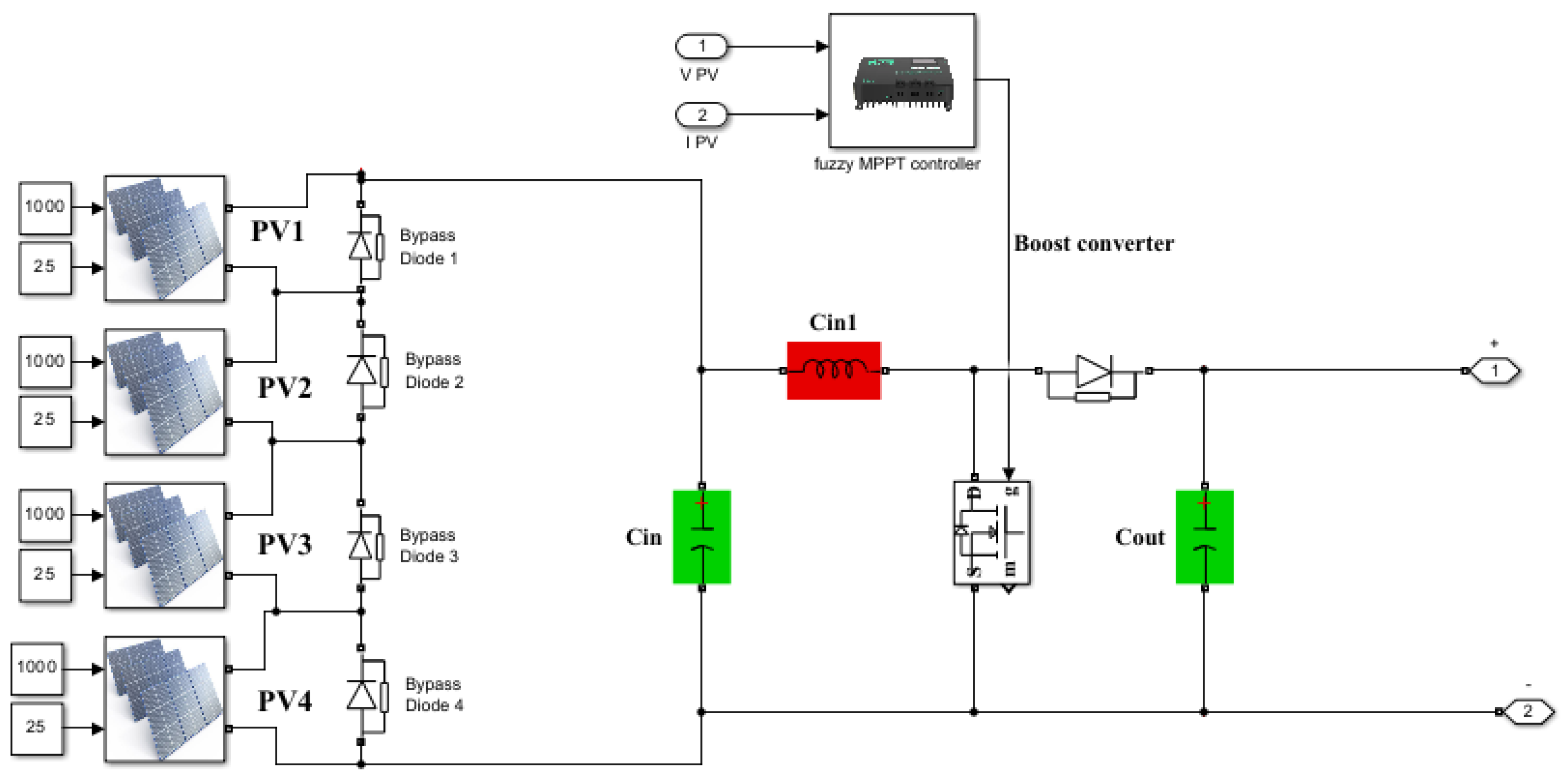
Figure 1. CBC integrating four-PV system.
Eng 06 00201 g001
Figure 2. IBC integrating four-PV system.
Eng 06 00201 g002
Figure 3. CBC PV grid system.
Eng 06 00201 g003
Figure 4. IBC integrating PV gird system.
Eng 06 00201 g004
Figure 5. Fuzzy logic controller design.
Eng 06 00201 g005
Figure 6. (a) Fuzzy controller logic design. (b) Membership functions.
Eng 06 00201 g006aEng 06 00201 g006b
Figure 7. The schematic of voltage source converter.
Eng 06 00201 g007
Figure 8. Simulation diagram of each PV topology under (a) constant irradiation and (b) different irradiation levels.
Eng 06 00201 g008
Figure 9. Duty cycle for each PV system with (a) constant irradiation and (b) different irradiation levels.
Eng 06 00201 g009
Figure 10. DC output current of the proposed IBC-based fuzzy MPPT under constant weather conditions.
Eng 06 00201 g010
Figure 11. DC output power of the proposed IBC-based fuzzy MPPT under constant weather conditions.
Eng 06 00201 g011
Figure 12. DC output voltage of the proposed IBC-based fuzzy MPPT under constant weather conditions.
Eng 06 00201 g012
Figure 13. AC voltage inverter measurements after filtering using IBC under constant weather conditions.
Eng 06 00201 g013
Figure 14. Spectrum of the voltage THD of the proposed IBC-based fuzzy MPPT under constant weather conditions.
Eng 06 00201 g014
Figure 15. DC output voltage of the proposed IBC-based fuzzy MPPT under partial shading conditions.
Eng 06 00201 g015
Figure 16. DC output current of the proposed IBC-based fuzzy MPPT under partial shading conditions.
Eng 06 00201 g016
Figure 17. DC output power of the proposed IBC-based fuzzy MPPT under partial shading conditions.
Eng 06 00201 g017
Figure 18. AC voltage inverter measurements after filtering using IBC under PSCs.
Eng 06 00201 g018
Figure 19. Spectrum waveform of voltage inverter for IBC under PSCs.
Eng 06 00201 g019
Figure 20. DC output current of the CBC-based fuzzy MPPT under CLI.
Eng 06 00201 g020
Figure 21. DC output power of the CBC-based fuzzy MPPT under CLI.
Eng 06 00201 g021
Figure 22. DC output voltage of the CBC-based fuzzy MPPT under CLI.
Eng 06 00201 g022
Figure 23. AC voltage inverter after filtering with CBC under CLI.
Eng 06 00201 g023
Figure 24. Spectrum waveform voltage inverter after filtering with CBC under CLI.
Eng 06 00201 g024
Figure 25. DC output power of the CBC-based fuzzy MPPT with partial shading conditions.
Eng 06 00201 g025
Figure 26. DC output current of the CBC-based fuzzy MPPT with partial shading conditions.
Eng 06 00201 g026
Figure 27. DC output voltage of the CBC-based fuzzy MPPT under PSC.
Eng 06 00201 g027
Figure 28. AC voltage inverter after filtering with CBC under PSC.
Eng 06 00201 g028
Figure 29. Spectrum waveform voltage inverter with CBC under PSCs.
Eng 06 00201 g029
Table 1. Specifications of PV panels and simulated system and parameters of IBCs.
ParameterValue
A10 Green technology A10J-S72-175 panel1 Series × 1 Parallel
Maximum Power175.09 W
Open circuit voltage Voc43.99 V
Short-circuit current Isc5.71 A
Voltage at maximum power point Vmp36.63 V
Current at maximum power point Imp4.78A
Inductor L0.1 mH
Output capacitance C o u t 12,000 μF
Duty ratio d 0.4
Input voltage converter each PV38 V
Vin total input voltage boost converter152 V
Vout output voltage boost converter250 V
Table 2. Fuzzy rules for system.
Error (E)/dENBNSZPSPB
NB (Negative Big)NBNBNBNSZ
NS (Negative Small)NBNBNSZPS
Z (Zero)NBNSZPSPB
PS (Positive Small)NSZPSPBPB
PB (Positive Big)ZPSPBPBPB
Table 4. Output voltage, current, power, and THD for each converter under CLI and PSC.
ConverterCLI PSC
Output Current DCOutput Voltage DCOutput Power DCTHD Voltage ACEfficiencyOutput Current DCOutput Voltage DCOutput Power DCTHD Voltage ACEfficiency
IBC2.962507380.76%99.72%2.32004500.93%97.82%
CBC3.42207001.35%93.58%2.21603801.87%92.63%
Table 5. Output voltage and power, THD, efficiency, and MPPT technique for different studies.
ReferenceOutput PowerInput VoltageOutput VoltageMPPT TechniqueTHDEfficiencyConverter TypeApplications
Hassan M. H. [6]150 KW120220 VPSO
P&O
--Interleaved Boost Converter (IBC)Grid-Connected PV
Girish Ganesan [49]100 W280174--92%Hybrid IBCRenewable Energy Applications
Ersan Kabalci [50]3 kW200250Kalman Filter (EKF)-Nor:99%
PSC:96%
IBCUnder PSC
Sen-Tung Wu [51]1.5 kW20–125 V400 V--93.57%Interleaved Boost Serial Resonant ConverterFuel Cell Battery
Shin-Ju Chen [28]1 kW36 V400 V--95.69%IBCRenewable Energy Applications
K. Krishnaram [52]2 kW150416 VANN- P&O-99.80%IBCPV system
Hasan Uzmus [53]400 W135 V400 Vmodified P&O-95%Hybrid IBCPV System
Farhan Mumtaz [54]1.26 kW 20 V400 VP&O3.22% IBCFuel Cell Power in a Microgrid
Radhia G [55]642 W-140 VANN-DISM 99.84%IBCUnder Partial Shading
Avinash M [56]-25 V50 VFO-PID controller--IBCFuel Cell-Based Electric Cars
Fahrul Indra [57]-50 V55 V-3.3%-IBCRenewable Energy
Proposal IBC for normal 735 W152 V250 VFuzzy logic
MPPT
0.76%99.72%IBCUnder Normal
PV Conditions
Proposal IBC for PSC450 W152 V220 VFuzzy logic
MPPT
0.93%97.82%IBCUnder Partial Shading PV Conditions
Disclaimer/Publisher’s Note: The statements, opinions and data contained in all publications are solely those of the individual author(s) and contributor(s) and not of MDPI and/or the editor(s). MDPI and/or the editor(s) disclaim responsibility for any injury to people or property resulting from any ideas, methods, instructions or products referred to in the content.