Article

Washout-Filter Power-Sharing-Based Resilient Control Strategy for Microgrids Against False Data Injection Attacks

1
Shanghai Electric Digital Technology Co., Ltd., Shanghai 200233, China
2
College of Information Science and Technology, Donghua University, Shanghai 201620, China
*
Author to whom correspondence should be addressed.
Eng 2025, 6(8), 198; https://doi.org/10.3390/eng6080198
Submission received: 27 June 2025 / Revised: 29 July 2025 / Accepted: 6 August 2025 / Published: 8 August 2025
(This article belongs to the Section Electrical and Electronic Engineering)

Abstract

Secondary control (SC) under false data injection attacks (FDIAs) in microgrids can compromise control decisions and disrupt the normal operation of the system. This paper proposes a washout-filter power-sharing-based resilient control strategy to tackle FDIAs. This strategy ensures the primary control continues to function normally by enabling the timely disconnection of the attacked SC. To address the under-rated operation state caused by the loss of SC, washout-filter power sharing is activated to restore the rated operation. Furthermore, for the FDIAs that affect both system frequency and voltage simultaneously after power sharing, a voltage compensation control loop is designed for the local voltage drop, allowing the attacked voltage value to further recover to the rated value. This strategy secures a steady frequency and enhanced voltage amplitude in the system, achieving a resilient effect against FDIAs. The proposed strategy has been validated through various simulation scenarios and FPGA-in-the-loop experiments.

1. Introduction

Microgrids are compact and manageable power networks that incorporate distributed generators (DGs), like hydrogen fuel cells, photovoltaic systems, and wind generators. They function efficiently with a hierarchical control structure, including primary, secondary, and tertiary controls [1]. Primary control (PC) typically uses droop control to promptly adjust the output power of DGs, aiming to suppress fluctuations in frequency and voltage. Secondary control (SC) addresses deviations from primary droop power sharing, after restoring frequency and voltage to rated values and obtaining grid synchronization signals to achieve grid integration. Among the various methods, distributed SC with cooperative autonomous regulation has attracted significant research interest [2,3].
In order to enhance multi-energy complementarity between regions, the concept of virtual power plants (VPPs) has been developed to integrate multiple microgrid clusters through a wide-area communications network to form a dispatchable entity with the characteristics of a “power plant”. This entity coordinates the participation of distributed resources in electricity markets and ancillary services at a higher level [4]. Its core value lies in breaking through geographical constraints, integrating microgrid distributed power generation output, energy storage regulation capability and load flexibility, and significantly reducing the uncertainty of new energy output. Reference [5] provides a systematic overview of the core concepts, diversified services, multiple control methods, differentiated optimization strategies, and practical application cases of VPPs and discusses the existing challenges and future trends in this field. Reference [6] proposes an artificial intelligence (AI)-driven integration framework for VPPs and smart grids, fusing deep reinforcement learning, blockchain, transformer, and federated learning to dynamically optimize multi-objectives, address data rigidity and privacy risks, and validate it with a Shenzhen case study that provides a scalable and secure practice path to achieve sustainable energy goals. Reference [4] systematically reviews and categorizes recent research advances on VPP modeling, focusing on its market and physical interactions, and reveals the trend of increasing complexity of VPP frameworks, extensive integration of market mechanisms, and increased energy policy adaptability through a classification framework covering model construction, computational methods, market strategies, and practical feasibility, aiming to identify efficient architectures and point out existing gaps. The aim is to identify efficient architectures and point out existing gaps. Reference [7] reviews VPPs’ development and three-layer structure (aggregation, communication, and core scheduling layers) and highlights the scheduling layer’s role as the “intelligent brain” for resource optimization. It examines current challenges and envisions VPPs’ potential in boosting renewable energy efficiency, energizing energy markets, and advancing low-carbon transitions.
Currently, there are research reports on the smart grid architecture model (SGAM), which provides a systematic framework for integrating VPPs and cybersecurity solutions into grid operations through interoperable mathematical modeling [8]. By combining Internet of Things (IoT)-enabled metering infrastructure with cloud computing and advanced metering infrastructure analytics, this approach enhances grid resilience while addressing cyber–physical threats in demand response scenarios [9]. The SGAM-based methodology offers solutions for optimizing VPP coordination and mitigating security risks. This paper also describes a study on the hierarchical defense capability of microgrids against cyberattacks within this SGAM framework.
The deep integration of power components and information technology makes microgrids, which are the underlying nodes of VPPs, vulnerable to false data injection attacks (FDIAs) [10]. FDIAs are generally meticulously designed to mislead control decisions by injecting false or manipulated data into the control system without being easily detected by the monitoring system [11,12]. Attacks on SC could cause problems like incorrect operation instructions, voltage frequency instability, and energy dispatch disorder, leading to physical equipment damage, abnormal operation, and overall system destruction.
Microgrids are cyber–physical systems, where the SC relies on the cyber layer for information exchange. In recent years, cyberattacks targeting power systems have become increasingly frequent, with their destructive impact growing more pronounced. For example, the cyberattacks on Ukraine’s power grid in 2015 and 2016 caused widespread blackouts, clearly exposing the vulnerability of traditional power systems in terms of cybersecurity [13]. Cyberattackers often exploit open interaction features of SC for FDIAs, tampering with references in power signal transmission. Cybersecurity in renewable energy microgrids is a multi-disciplinary challenge: the energy transition increases system dynamics, and greater intelligence extends attack chains, requiring cyberresilience solutions that integrate power electronics, communications, cryptography, and intelligent algorithms. Reference [14] systematically reviews cyberresilience in renewable smart microgrids, focusing on communication technology vulnerabilities, attack mitigation solutions, and practical recommendations with future research directions. Reference [15] experimentally validates a four-layer IoT architecture (sensing, network, middleware, application) in microgrids, demonstrating its feasibility through remote monitoring. Reference [16] comprehensively analyzes microgrid cybersecurity vulnerabilities and communication protocol risks, identifies limitations in existing protections, proposes layered security strategies, and highlights critical research gaps.
In order to enhance the stability and reliability of microgrids, many studies have concentrated on implementing resilient control to counter this threat [17,18]. A fuzzy resilient control method is proposed in [17] to stabilize systems affected by parameter changes and constant power loads. In [19], a fully distributed attack-resilient adaptive control framework is presented to cope with unknown unbounded attacks, ensuring frequency and voltage stability and consensus. To enhance the anti-interference capability of islanded microgrids against FDIAs, a resilient secondary control method based on unknown input observers is put forward in [20]. An advanced sensor monitoring and decision risk assessment framework, aimed at enhancing microgrid resilience against uncertain risks, is proposed in [21]. Reference [22] proposes an energy storage configuration method based on two-stage robust optimization, considering line faults, to enhance microgrid resilience. A resilient event-driven fault detection filter is introduced in [23], aiming to enhance the fault detection resilience of DC microgrids under denial-of-service (DoS) attacks. In [24], voltage and frequency are regulated in AC microgrids under FDIAs, using a distributed convergent observer-based resilient controller. Reference [25] proposes a resilient distributed secondary control strategy utilizing extended-state observers, which enhances the resilience of islanded AC microgrids. An adaptive fuzzy logic resilient control method is proposed in [26] to ensure the stability of microgrid frequency under the influence of FDIAs and parameter uncertainties. Reference [27] proposes a method based on the W-MSR algorithm, which enhances the resilience of multi-microgrid systems against false data injection and replay attacks by isolating malicious agents. Reference [28] implements resilient control via sliding mode control and offset compensation. A logic processor is designed in [29] to capture attack durations for resilient control implementation. A distributed resilient estimator is designed in [18] to resist topology attacks.
However, when it comes to resilient control against FDIAs, much of the existing literature focuses on droop-based power sharing without explicitly mentioning washout-filter sharing. This method is similar to droop-based power distribution and does not compromise the effectiveness of frequency and voltage control [30,31,32]. This potential is crucial for mitigating FDIAs. In the context of the microgrid hierarchy, SC can be disconnected if necessary. Even after disconnection, PC can maintain stable and reliable operation independently. This analysis demonstrates the feasibility and effectiveness of timely isolating SC when this control is identified as being attacked. Moreover, a method to improve frequency and voltage on the PC layer to demonstrate the resilient effect is identified, as washout-filter power sharing proves highly competent. In addition, due to the local characteristics of the system voltage, such as voltage drop caused by line losses and load distribution, as well as both frequency and voltage being susceptible to FDIAs, the voltage value still cannot return to the rated value after power sharing switching. By analyzing the mechanism of the SC, i.e., the SC algorithm calculates the required frequency or voltage compensation and adds this to the PC to correct any deviations caused by the PC. So, is it also possible to design a control loop on the PC layer to eliminate deviations after the SC is cut off? Thus, this paper further designs a voltage compensation control loop (VCCL) for the local voltage drop, which can further return the voltage to the rated value at the PC layer.
This study investigates the robustness of attacked SC removal and washout-filter-based power sharing against FDIAs, particularly analyzing the role of each DG’s voltage source converter (VSC) in AC microgrids with distributed SC architecture. Following this, the washout-filter power-sharing-based resilient control (WFPS-RC) strategy is proposed. This strategy has proven effective across multiple simulation scenarios. Its validity was further confirmed through FPGA-in-the-loop (FIL) testing, which closely replicates real-world network attack defense conditions. To conclude, the key contributions presented in this paper are as follows:
(1)
The removal of the attacked SC will avoid significant impacts on the PC and other DGs. The system will transition to an operating state with only the PC, and the washout-filter power sharing will replace the droop-based sharing, achieving system frequency and voltage recovery.
(2)
Unlike the global nature of system frequency, local voltage may still not be able to return to the rated value under the effect of washout-filter power sharing. In this case, a VCCL on the PC layer will be designed to further correct the voltage to the rated value. Moreover, the VCCL exhibits the ability to mitigate the propagation of FDIAs.
(3)
The proposed WFPS-RC strategy isolates the attacked SC, restoring frequency and voltage to its rated value at the PC layer. This enhances the system’s overall resilience, ensuring that, even after suffering FDIAs, the system can still maintain its original secondary control effectiveness.
The paper is structured as follows: Section 2 describes primary and secondary controls, Section 3 details FDIAs and the proposed strategy, Section 4 provides verification, and Section 5 presents the concluding remarks.

2. Primary and Secondary Controls

In this section, the configuration of the PC and SC will be provided, where the PC primarily handles droop control and power conversion and the SC then rectifies the frequency and voltage offsets generated by the PC. Among them, the implementation of the SC is the PC plus the compensation amount generated by the distributed control method.

2.1. Droop-Based Power Sharing at the PC Level

The droop-based power sharing control method is commonly used at the PC level. This method balances power between DGs by adjusting the output voltage amplitude and frequency of the converters, ensuring the voltage and frequency stability of the microgrid using the following formula.
f = f * m P
E = E * n Q
where f * and E * are the rated frequency and voltage, while P and Q represent the measured active and reactive power, respectively. The variables m and n denote droop coefficients.

2.2. MPC-Based Power Conversion at the PC Level

Using model predictive control (MPC)-driven power conversion has multiple advantages in the PC of microgrids, including precise modeling, intuitive control objects, and rapid response capabilities [33,34,35]. Droop control offers a voltage reference that includes frequency information for MPC-based power conversion. This reference indicates the necessary voltage level for the system to maintain autonomously. MPC then determines the optimal power conversion control instructions based on this information. This combination forms the PC architecture, and they can leverage their respective advantages. Below is the predictive model of the MPC [36,37].
x ( k + 1 ) = e A T s x ( k ) + A 1 ( e A T s I 2 × 2 ) B u ( k )
where x = V c I f , u = V i I o , A = 0 1 / C 1 / L R / L , B = 0 1 / C 1 / L 0 , Ts is the sampling interval, and I 2 × 2 represents an identity matrix. In this equation, the matrices are derived from the dynamic model of microgrid interface circuit, which maps the topology of the RLC circuit connected to the DG output inverter, serving functions such as filtering and primarily supporting MPC-based power conversion control.
Meanwhile, the cost function JVI utilized to determine the optimal switching variable follows this formula.
J V I = w V ( V c α , β * V c α , β ( k + 1 ) ) 2 + w I ( I f α , β * I f α , β ( k + 1 ) ) 2
where wV and wI are weight coefficients. Vc and If are the capacitor voltage and filter inductor current, respectively. The ones marked with * are their references. α and β denote the three-phase variables transformed using the Clarke transformation. The cost function solution yields optimal pulse width modulation (PWM) signals for the VSCs.

2.3. Graph-Based Distributed Cooperative Control at the SC Level

The SC of microgrids uses graph theory to show the connection relationships between DGs [38]. It employs a cooperative algorithm that allows intelligent agents to keep system parameters stable without the need for central coordination. Taking DG as a node, if node j transmits data to adjacent node i, node j is defined as a neighbor of i. The set of neighbors for node i is represented as N i = { j | ( v j , v i ) } , with an associated weight of a i j = 1 . In all other instances, a i j = 0 . The adjacency matrix A = [ a i j ] N × N , composed of aij, outlines the communication pathways for DGs and the reference transmission in the SC.
Distributed control strategies synchronize DGs to improve frequency and voltage regulation. By applying input–output feedback linearization, the complex system is simplified into linear subsystems [36,37].
f ˙ i = Δ f ˙ i m i P ˙ i u f i = e f i d f
E ˙ i = Δ E ˙ i n i Q ˙ i u E i = e v i d v
where · refers to the differential operation.
Consider the global characteristics of frequency and distribution of active and reactive power. The subsequent formula is applicable.
m i P ˙ i u p i = m i ( P i   1 ω c s + 1 P i ) d p
Q ˙ i = 1 ω c ( Q i Q i   1 ω c s + 1 )
where ω c represents the cutoff frequency. The above df, dv, and dp are the relevant control coefficients.
The tracking errors, denoted as efi and evi, are formulated as
e f i = j N i a i j ( f j f i ) + g i ( f * f i )
e v i = j N i a i j ( V c j V c i ) + g i ( V c * V i )
where gi is the pinning gain, indicating the DG is a root node when 1 and not when 0.
The protocols for distributed SC cover both frequency and voltage, specifying the compensation added to the PC as
f c = ( u f i + u p i ) 1 s
E c = ( n i Q i · + u E i ) 1 s
Below is the complete formulation for droop-based power sharing with SC effect compensation.
f = f * m P + f c
E = E * n Q + E c
The diagram of the PC and SC structures and connections in one DG as well as the communication topology of the SC layer for four DGs is shown in Figure 1. This figure illustrates that the compensation amount, derived from a distributed secondary control structure, is integrated into the droop controller within the primary control. This integration results in the elimination of steady-state errors for both frequency and voltage. The communication architecture within the secondary distributed system employs a sequential transmission of reference values, originating from DG1 and progressing to DG4. In this architecture, DG1 serves as the root node that can obtain the rated values. The FDIA operates on the channel through which reference values are transmitted, such as the frequency and voltage amplitude f1 and E1 given from DG1 to DG2.

3. FDIAs and Proposed WFPS-RC Strategy

In this section, the FDIAs will be first described, then the washout filter’s recovery ability will be introduced, and its formula will be compared with droop control. Following that, the VCCL at the PC layer will also be presented, with its main purpose being to further compensate voltage. Finally, the proposed WFPS-RC strategy, which includes the above two parts, as well as how to specifically implement it, will be given.

3.1. FDIAs on SC

The FDIAs can compromise transmitted references within the network, potentially destabilizing the microgrid system [39,40]. The core idea of FDIAs is to inject a manipulated signal into the original using the following expression.
d ^ ( t ) = d ( t ) + d r ( t )
d r ( t ) = 0 ,   f o r   t τ r λ r F ( ) ,   f o r   t τ r
where d ^ ( t ) , d(t), and dr(t) are the disrupted, original, and tampered signals, respectively. τr is the attack duration. F( ) is the main function for attack effect, while λr modifies its strength. Regarding SC, d(t) symbolizes the transfer of frequency and voltage references.
The root node typically maintains frequency and voltage references using fixed controller values. For the ith node, the frequency and voltage values from the jth node are assumed to be impacted by FDIAs, outlined as follows.
e ^ f i = j N i a i j ( f ^ j f i ) + g i ( f * f i )
e ^ v i = j N i a i j ( V ^ c j V c i ) + g i ( V c * V i )
The impact of the FDIA-affected system extends from the SC layer to executive levels, posing risks to operational stability and safety.

3.2. Washout-Filter Power Sharing

This method merges droop-based power sharing with SC in the PC layer, preserving the distributed control structure. This can be described as [32]:
f c = k i f s ( f * f )
E c = k i E s ( E * E )
where kif and kiE represent the integral coefficients of linear SC and are also the frequency and voltage regulation coefficients of the washout filter. Substitute the f and E defined by Formulas (13) and (14) into the above fc and Ec, amalgamate similar terms, and solve for the relationship between fc and P as well as Ec and Q. Then substitute back into Formulas (13) and (14) to derive the following washout-filter-based expressions.
f = f * s s + k i f m P
E = E * s s + k i E n Q
The washout filter, a potential replacement for the droop-based method, has reshaped power sharing. Compared to droop control, it can be seen that a first-order high-pass filter transfer function is multiplied before the droop coefficient. In fact, the washout filter functions as this kind of filter, effectively eliminating the DC component while allowing the transient component of the signal to pass through. Its control performance under FDI will be discussed next.
To a certain extent, washout filters can influence the transient response due to their high-pass characteristics. However, they do not affect the steady-state power sharing accuracy because they attenuate DC components, including both FDIA biases and steady-state deviations, to zero. The transient response can be adjusted by appropriately selecting the coefficients kif and kiE, enabling the system to preserve normal load dynamics while effectively attenuating relatively slow-varying FDIA signals. It is noteworthy that the proposed strategy exhibits a balanced coordination between enhanced robustness against attacks and the maintenance of power sharing performance.

3.3. VCCL

To accurately adjust the voltage to its rated value, this subsection will introduce the voltage compensation control loop (VCCL) which is implemented at the PC layer. Unlike the system frequency, which has a global characteristic, local voltage may still deviate from its rated value due to the influence of washout-filter power sharing. The SC algorithm determines the necessary frequency or voltage adjustments and incorporates these modifications into the PC to rectify any deviations introduced by the PC. This mechanism serves as a reference for the further recovery of voltage to its rated value after the washout filter is engaged. The following control loop is designed to achieve this task, added to the PC control layer as compensation.
e E c l = V c E E c l = k p E c l + k i E c l 1 s e E c l
This voltage compensation can be used to address strong FDIAs on the system, such as simultaneous attacks on frequency and voltage, to compensate for the inability of the washout filter to achieve rated value recovery. Given that the VCCL utilizes an integral controller, a limiting module must be incorporated at the controller output to prevent integral saturation. The limiting module serves as a critical component for maintaining system stability in the presence of FDIAs, particularly during the transient phase before the defense algorithm is fully activated. By constraining the impact of compromised signals, it helps prevent the propagation of malicious data and enhances the system’s resilience under attack conditions.

3.4. Proposed WFPS-RC Strategy

To fully utilize the washout-filter features and achieve a resilient control effect under the FDIA, the following protocol will be designed.
f = f * g s 1 m P g s 2 s s + k i f   m P
E = E * g s 3 n Q g s 4 s s + k i E   n Q + E c l
where gs1, gs2 and gs3, gs4 represent two sets of control gains, specifically associated with frequency and voltage compensations, respectively.
The proposed WFPS-RC strategy contains two parts. The first part is to cut off SC, meaning the compensation produced by distributed SC is set to zero. The second part is to switch the power sharing mode in the PC layer. Therefore, the following rules for triggering and assignment are hereby established.
f c = E c = 1 ,   t Τ 1   g s 1 = g s 3 = 1 ,   g s 2 = g s 4 = 0 ,   t Τ 2   :   if   FDIA   is   f a l s e
f c = E c = 0 ,   t Τ 3   g s 1 = g s 3 = 0 ,   g s 2 = g s 4 = 1 ,   t Τ 4   :   if   FDIA   is   t r u e
The time intervals T1 and T2 represent periods without FDIA, whereas T3 and T4 correspond to periods during which FDIA is present. To flexibly handle network attacks, T3 and T4 can commence simultaneously. Alternatively, T3 can initiate first to disconnect the under-attack SC, followed by switching the power sharing in T4 to achieve resilient effects. Here, to ensure the integrity of the system power sharing and power conversion control architecture between different operations, while maintaining simple control logic, the deactivation of SC and activation of the washout filter are configured to occur simultaneously. This simultaneous operation is achieved through synchronized control logic.
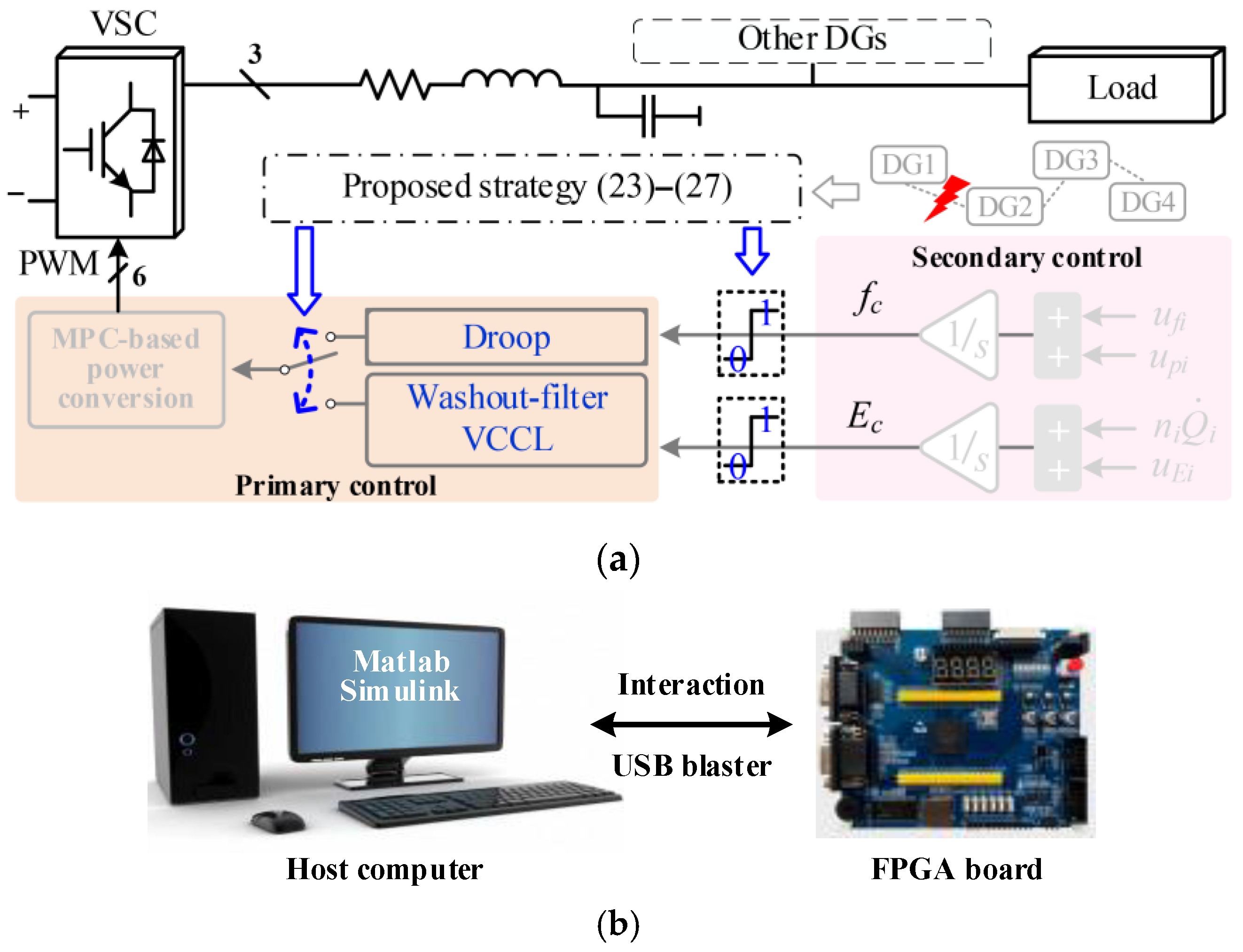
The proposed WFPS-RC strategy is shown in Figure 2a. The figure illustrates that, when a DG experiences the FDIA, the proposed control strategy initiates the appropriate control algorithm. This process involves transitioning from droop power sharing to a washout filter and implementing a VCCL for voltage stabilization. Subsequently, MPC-based power conversion is used to generate the required PWM control signals for the VSC. Figure 2b shows the FIL platform constructed in this paper, with a USB Blaster cable connecting a computer to an FPGA board. The FPGA will be manually operated to generate FDIAs, then the produced attacks are injected into the simulation model. The WFPS-RC strategy proposed in this paper is designed to implement the defense and elimination of external network attacks within the model. This FIL configuration, leveraging the FPGA’s hardware acceleration capabilities to generate network attack signals in real time, more closely resembles real-world network attacks. This approach makes the attack vector more explicitly transmitted through communication lines into the system model. Meanwhile, the proposed algorithm operates at the control level to defend against and eliminate incoming attacks.

4. Verification

In this section, a microgrid system of four DGs is constructed. Here, the algorithm development is carried out on a host computer (Intel Core i7 CPU, 40 GB RAM, Windows 11) using MATLAB/Simulink R2022b. The reference value transmission paths of these four DGs are as described earlier. In the following simulation scenarios, the frequency and voltage reference values received by DG2 from DG1 will be first considered to have been subjected to an FDIA. The system operates at a rated frequency of 50 Hz and the root mean square value of the line rated voltage is 380 V. The frequency f and voltage Vc are both collected from the filter output of DG VSC. In the following validation scenarios, the VCCL is equipped on DG2 to DG4, while DG1 is not configured for comparison. To distinctly demonstrate the compensation effect of the VCCL in the proposed strategy, its control performance is showcased starting from scenario 4.3.

4.1. Situation of DG2 Suffering from FDIA

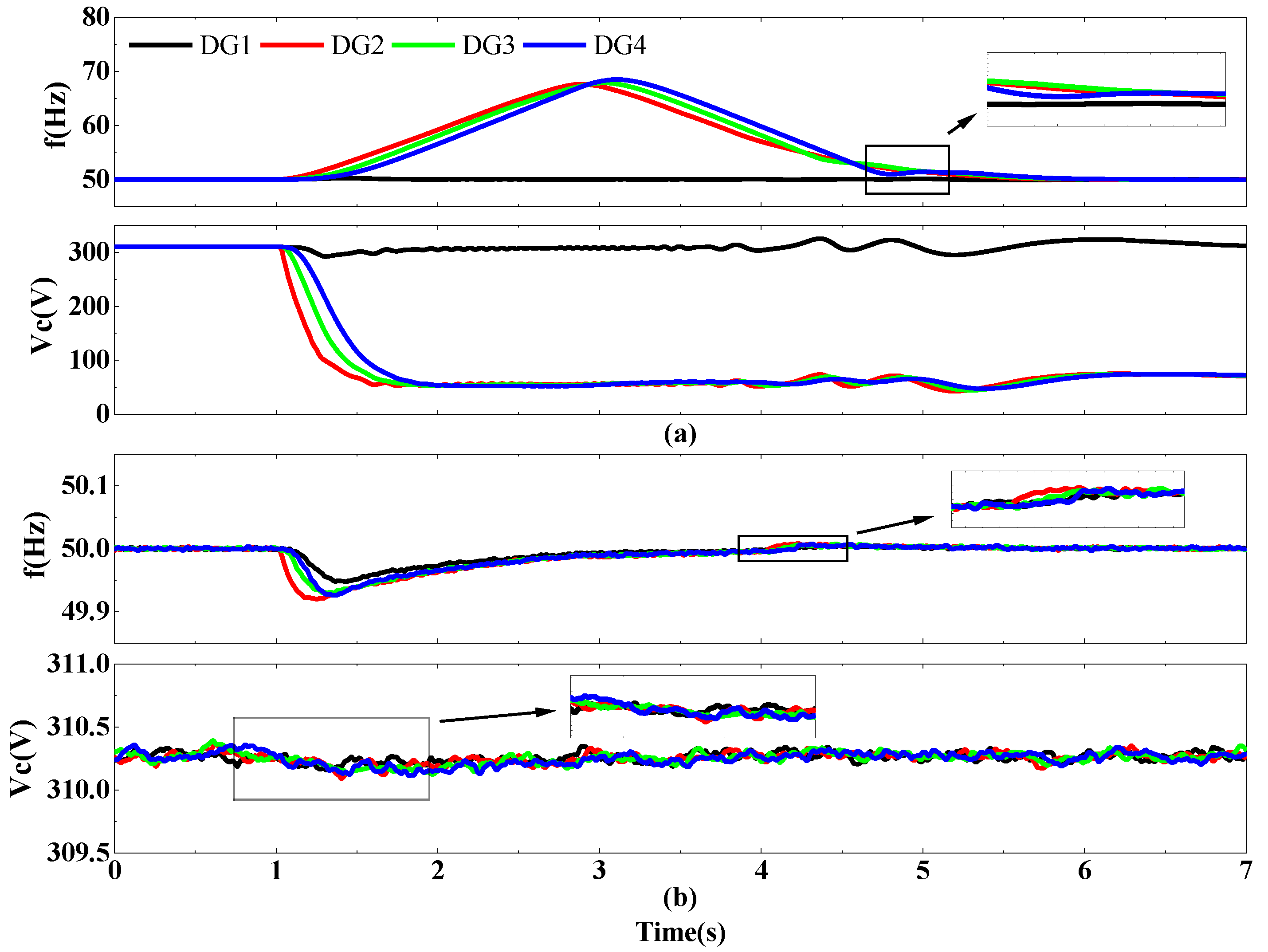
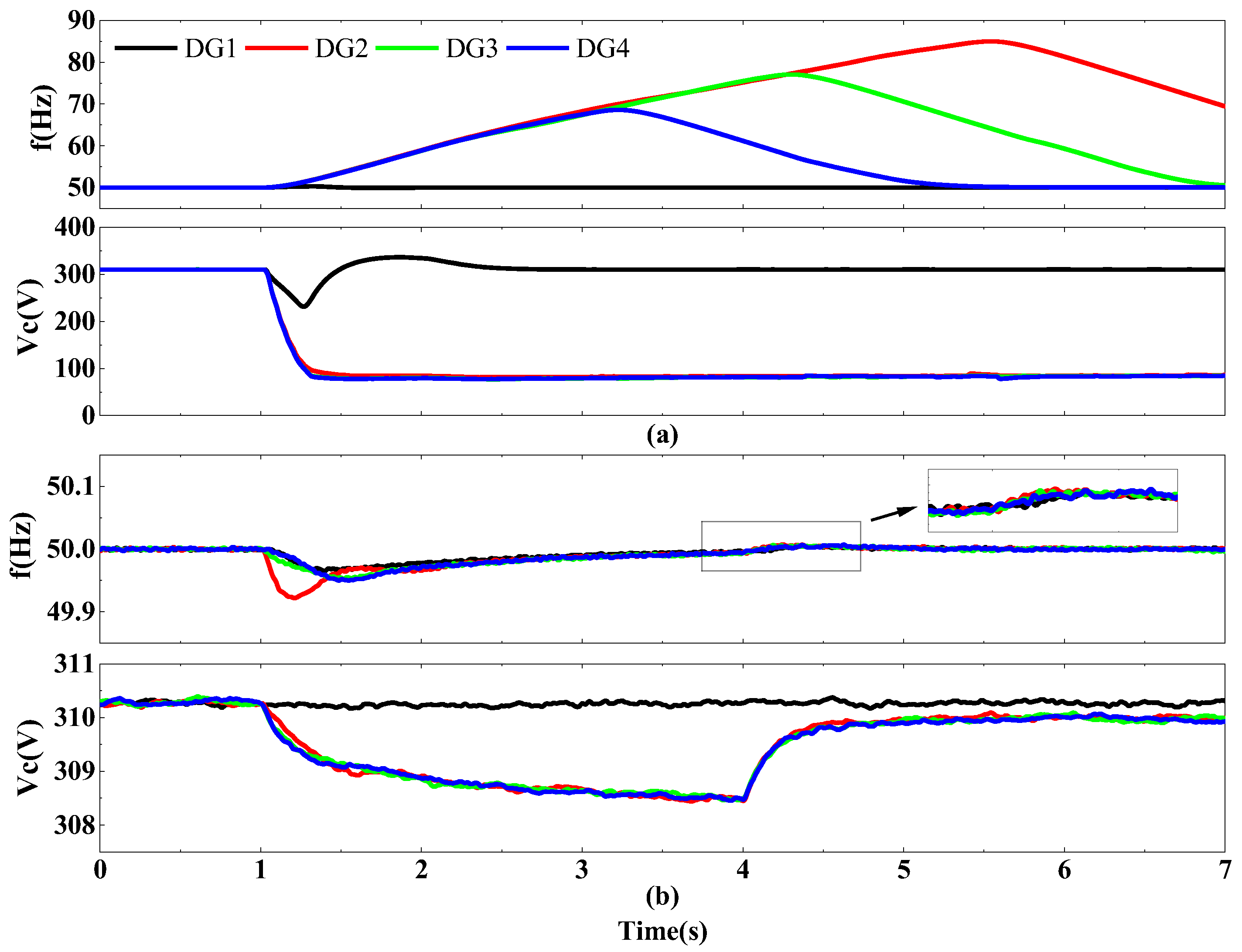
First, the FDIA will increase the frequency reference transmitted from DG1 to DG2 by 100 units at 1 s, as displayed in Figure 3. Figure 3a shows the attacked effect without any defense algorithms. DG3 and DG4, both located behind DG2, lose control under the attack. Although DG1 is not directly targeted and continues to operate, it still experiences side effects. These include fluctuations in frequency and gradual oscillations in voltage amplitude. As shown in Figure 3b, DG2 initiates the soft disconnection (SC disconnection) at 1 s using the proposed WFPS-RC strategy. Subsequently, at 4 s, the droop control mode transitions to a washout-filter-based power sharing method. All subsequent simulations presented in this study follow this predefined sequence of control actions, ensuring consistency in evaluating the system’s dynamic response and stability. After SC is cut off, system frequency gradually returns to the rated value due to its global nature and local recovery ability. However, the system frequency returns back to the rated value without steady-state error after 4 s, owing to the washout filter. At 1 s, Vc decreases but can eventually recover to the rated state.
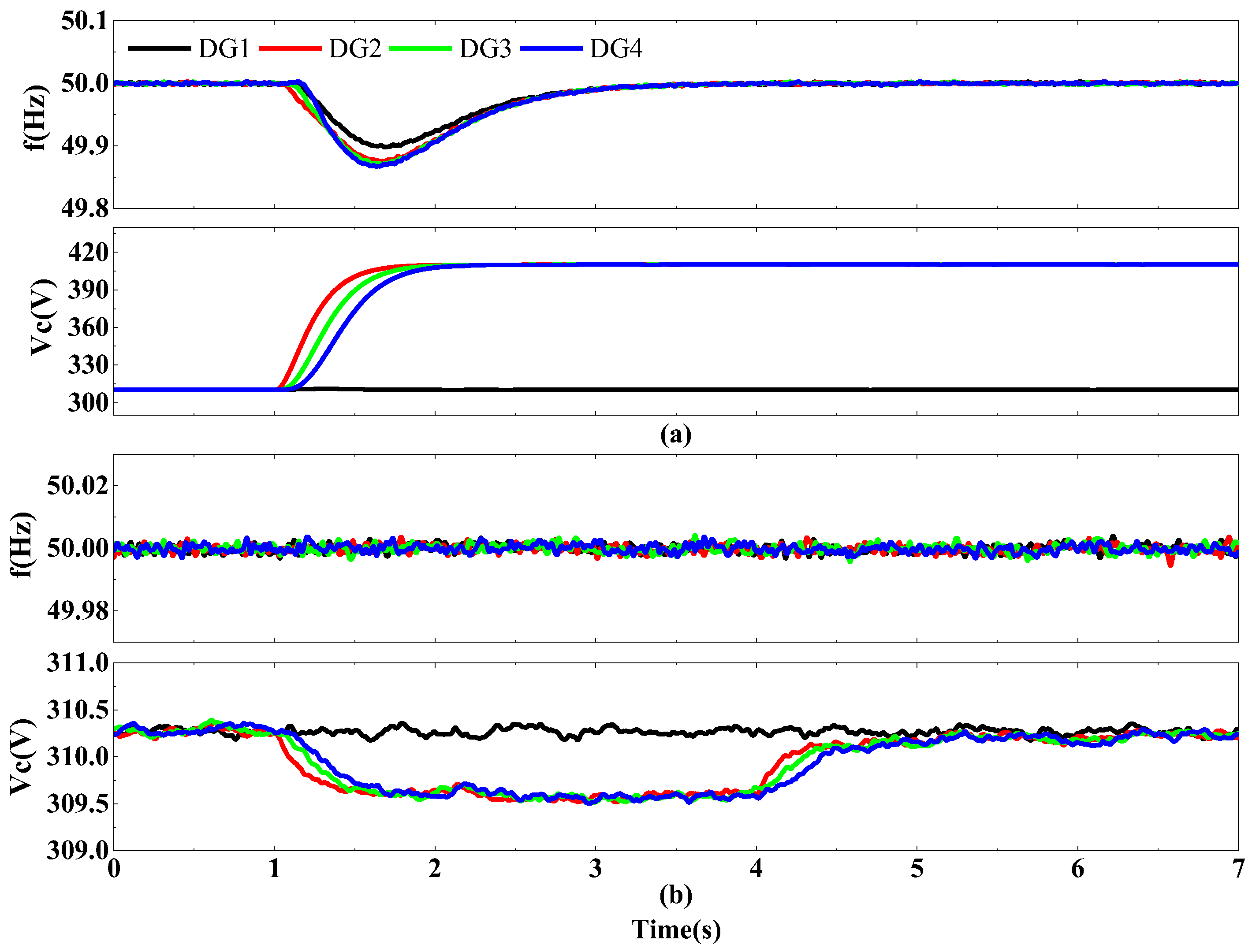
Next, the FDIA will increase the voltage reference transmitted from DG1 to DG2 by 100 units, and the result is depicted in Figure 4. In Figure 4a, the voltage suffers the most direct attack, with its amplitude experiencing a steady deviation, but it remains stable after more than 1 s. Meanwhile, the frequency is also affected, although it did not receive a direct attack; the frequency undergoes a transient decrease for more than 1 s, after which it returns to its rated value. Figure 4b shows that the frequency is almost unaffected by using the proposed WFPS-RC strategy. Despite a drop after 1 s, the voltage recovers to its rated value by 4 s, ensuring stable operation. At the same time, to distinguish the control effect of the VCCL, Vc will be presented in two separate diagrams.
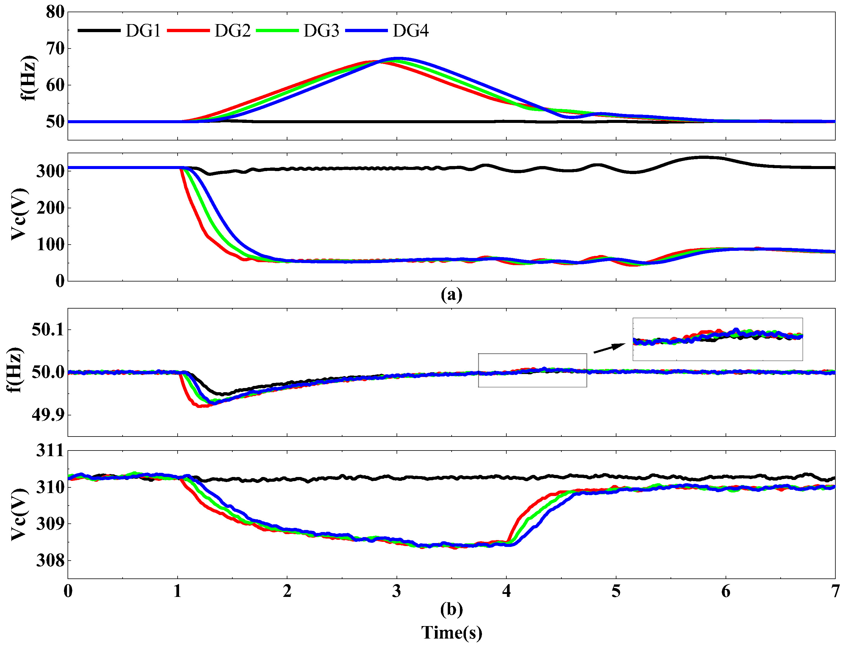
Then, the FDIA will further increase 100 units each in the frequency and voltage references transmitted from DG1 to DG2. The results are displayed in Figure 5. It reveals that the FDIA’s comprehensive impact on the system has increased in comparison to previous attacks that only targeted frequency and voltage, as evidenced by more intense fluctuations in frequency and voltage. However, fortunately with the help of the proposed WFPS-RC strategy, the system can restore frequency to the rated value and achieve some voltage compensations close to the rated value. Although the voltage stabilizes below rated values after 4 s, the system mitigates the attack impact to an acceptable range (significantly reduced from a maximum of about 1.86 V when under attack to about 0.25 V after using the proposed strategy). Also, no major voltage fluctuations occur when the system is stable. This frequency recovery and voltage compensation brought about by the switching of power sharing methods brings the system’s operating state closer to its rated state, which demonstrates the effect of resilient control.

4.2. Situation of DG2 to DG4 Suffering from FDIA

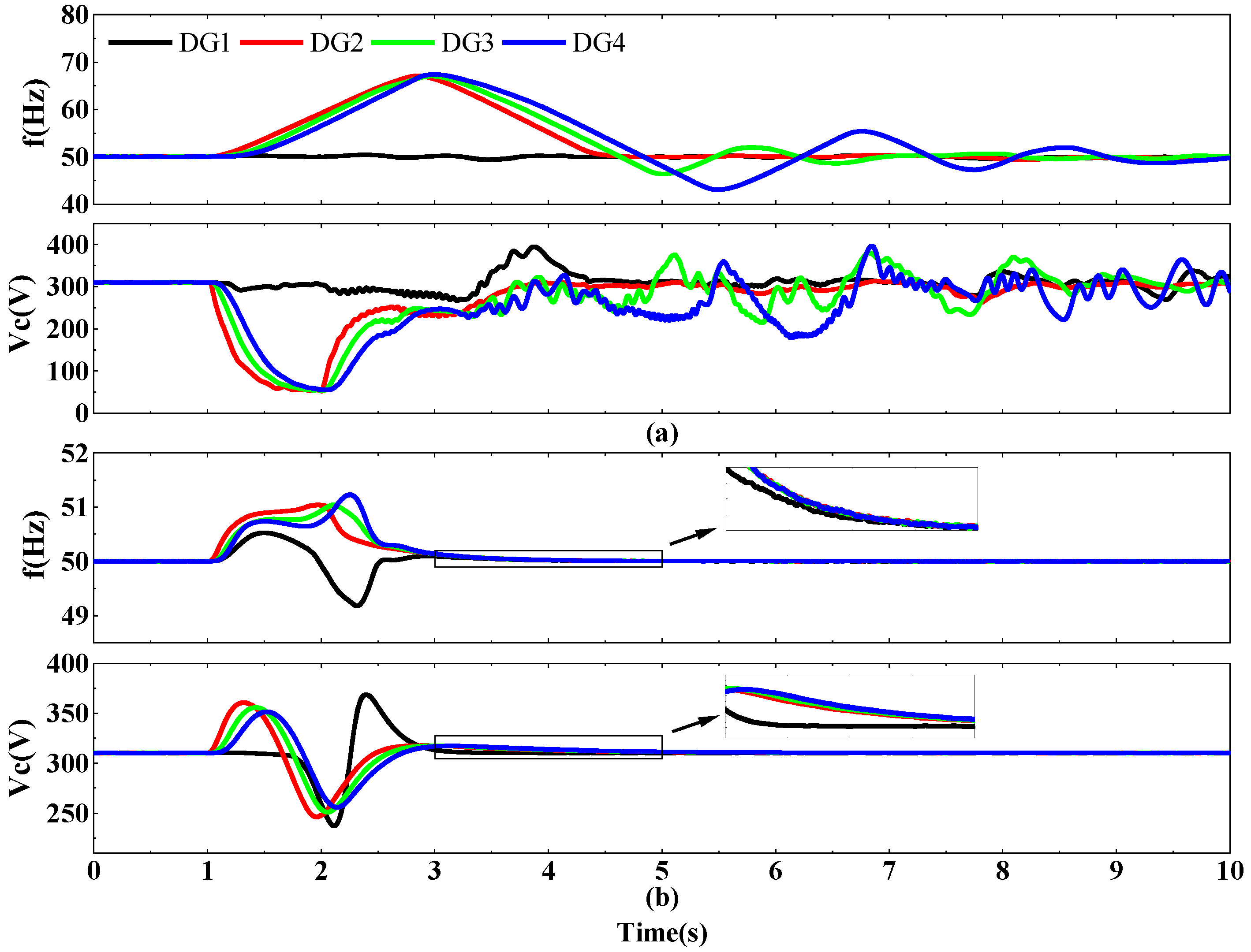
To further verify the effectiveness of the proposed WFPS-RC strategy, the FDIA will simultaneously and suddenly increase the frequency and voltage references by 100 units from the upper reference signal received by DG2 all the way to that received by DG4. Figure 6 compares the relevant results. In Figure 6a, it is shown that the attack’s impact on the entire system has increased significantly compared to the case where only a single DG receiving channel is subjected to an FDIA. Nevertheless, by using the proposed strategy, the system maintains its capacity to effectively mitigate this impact. As shown in Figure 6b, the system successfully restores the frequency to its rated value within approximately 5.5 s. Meanwhile, the voltage remains stably regulated near the nominal level, demonstrating the effectiveness of the control strategy in maintaining both frequency and voltage stability under the given operating conditions.

4.3. VCCL Effect

From the previous simulation results, it can be observed that, when the system is subjected to relatively severe FDIAs, such as when one or multiple DGs’ frequency and voltage are affected, using the power sharing method in the proposed strategy is not sufficient to restore the voltage to its rated value without deviation. Therefore, benefiting from the proposed VCCL method, the system voltage will receive further compensation, bringing it to its rated value. Figure 7 compares results when the VCCL activates at 7 s, based on previous simulations. From Figure 7, it can be observed that, even though the power sharing was switched to the washout-filter method, the voltage remained stable in the period of 4–7 s but continued to operate below the rated level. Subsequently, after 7 s, the voltage profile exhibits a further increase, stabilizing at the rated value. Regardless of whether one DG or multiple DGs experience FDIAs, the proposed VCCL can effectively restore both frequency and voltage to their rated values.

4.4. System Performance After the SC Delay Cutoff

In the previous simulation, facing the FDIA, the immediate removal of SC was first simulated. However, in some cases, there might be a delay in the removal of SC, so it is crucial to assess the system’s performance under conditions where there is a delay in SC cutoff. Therefore, in this scenario, not removing SC at the moment of attack but rather allowing the attack to continue for a short period, followed by the removal of SC and the implementation of the proposed strategy, will be evaluated. The comparison of the system’s control performance and effectiveness is shown in Figure 8. Here, the FDIA initiates at 1 s and persists for 1 s; the system’s performance without and with the VCCL is presented. As can be seen from Figure 8, when using the VCCL method, the system maintains control during the ongoing attack, in contrast to the situation without VCCL implementation. This is due to the limiting module in the VCCL. When the system reconnects to the proposed complete strategy after 2 s, it can quickly recover to its previous rated value. Thus, the VCCL can also incorporate functionality to mitigate the propagation of attack effects.

4.5. Verification of Random Attacks by FIL Experiments

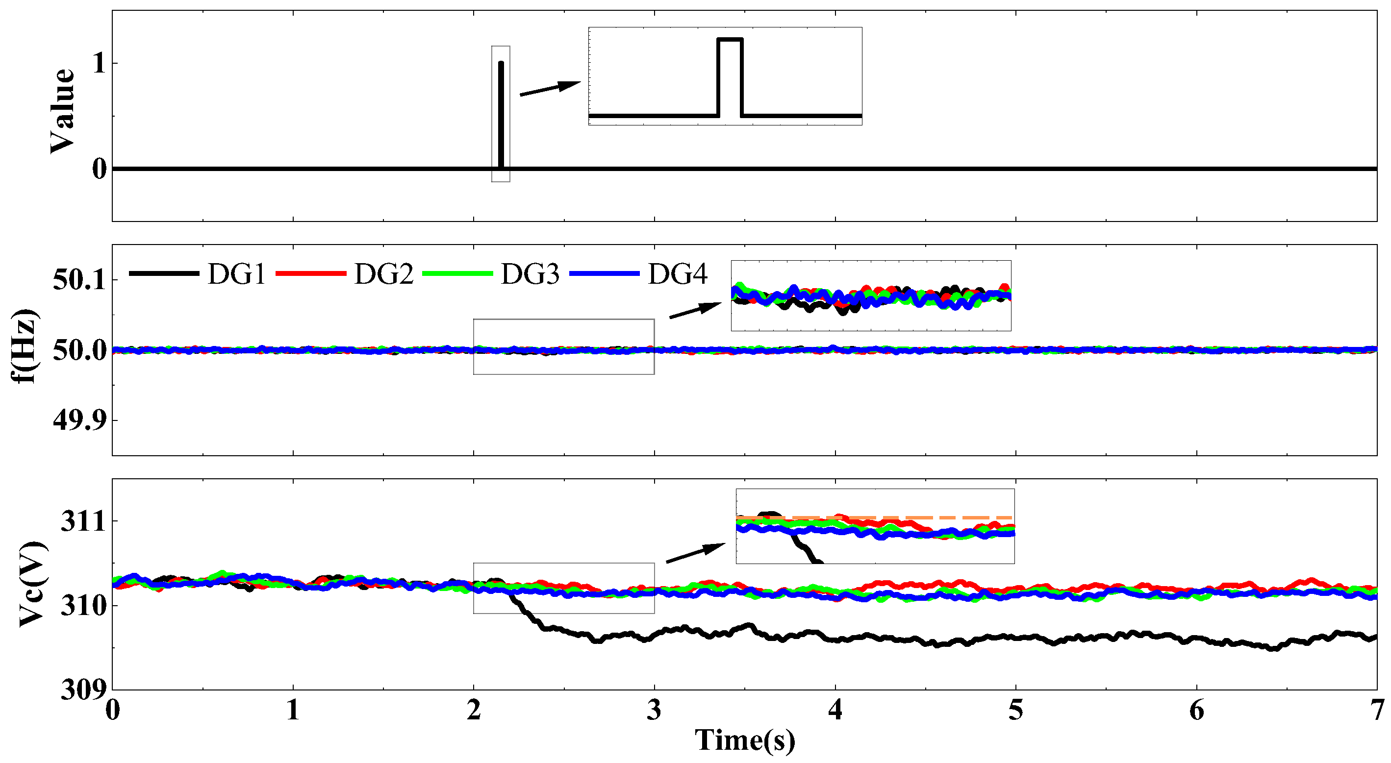
With the FIL setup in Figure 2b, the FPGA will randomly implement an FDIA, where SC removal and power sharing switch occur simultaneously. The most severe attack begins, with four DGs concurrently subjected to FDIA, including modifications to the constant reference acquired by DG1. DG1 is not equipped with a VCCL, while the other three DGs are all configured with it. As shown in Figure 9, the attack starts just after 2 s and lasts for a very short time. This causes fluctuations in the system frequency and voltage under the proposed WFPS-RC strategy, but the system is still able to operate stably. Specifically, the FDIA temporarily decreases DG1’s frequency and then it regains rated value, while other DGs’ frequencies remain stable. Additionally, the FDIA causes a steady decrease of about 0.5 V in DG1’s voltage and slight drops in other DGs’ voltages. The FIL experiment here further demonstrates the effectiveness of the proposed WFPS-RC strategy.

5. Conclusions

From the perspective of designing control algorithms within the controller, this study proposes an effective WFPS-RC defense strategy against FDIAs that affects the SC layer of microgrids. The strategy involves rapid disconnection of the attacked control layer, thereby preventing the cascading spread of security threats to the PC layer. By isolating the compromised component, the strategy ensures the continued stable operation of unaffected DGs and contributes to the robustness and fault tolerance of the overall microgrid control architecture. It adopts a power sharing mechanism using washout filters. This allows for frequency and voltage compensation, making sure the system can swiftly return to its standard operating state. Furthermore, in order to compensate for the residual voltage deviations not addressed by the washout filter, the proposed VCCL effectively mitigates these errors. This enhancement ensures that the system maintains operation close to the rated voltage level, improving the regulation accuracy at the nominal operating point. The VCCL also helps stop FDIAs from spreading, especially during the initial phase when the defense algorithm has not yet fully activated in response to an ongoing attack. Thus, the stability and resilience of the microgrid are maintained. This WFPS-RC strategy has proven to be effective with various simulation scenarios and is robust enough to handle physical external injection attacks via the FIL.
Although the WFPS-RC strategy proposed in this study effectively defends against FDIAs on the SC layer, future work will focus on more complex attack vectors and system topologies. First, the WFPS-RC framework will be extended to address a broader range of attack types beyond FDIAs, such as DoS attacks, and its robustness will be evaluated under multi-layer coordinated threats. Second, the resilient control mechanism will be further developed to enhance its adaptability in advanced operational scenarios. For instance, in systems assisted by machine learning, online learning techniques will be integrated to dynamically adjust control parameters, enabling the system to respond effectively to unknown or evolving attack patterns.

Author Contributions

Conceptualization, S.F. and Y.S.; methodology, S.F., W.Z. and Y.S.; software, W.Z., X.W. and Y.S.; validation, S.F., W.Z., X.W., T.Q. and Y.S.; writing—original draft preparation, S.F. and Y.S.; writing—review and editing, W.Z., X.W., T.Q. and Y.S. All authors have read and agreed to the published version of the manuscript.

Funding

This work was supported in part by the Shanghai Explorer Program, China under Grant 24TS1410100 and in part by the Fundamental Research Funds for the Central Universities, China under Grant 25D110417.

Data Availability Statement

The original contributions presented in this study are included in the article. Further inquiries can be directed to the corresponding author.

Conflicts of Interest

Author Shiwang Fan was employed by the Shanghai Electric Digital Technology Co., Ltd. The authors declare that this study received partial funding from Grant 24TS1410100. This paper only represents the opinions of the authors. The funding sponsors had no role in the design of the study; in the collection, analyses, or interpretation of data; in the writing of the manuscript; or in the decision to publish the results.

Abbreviations

Abbreviation/SymbolDescription
ACAlternating Current
AIArtificial Intelligence
DCDirect Current
DGDistributed Generator
DoSDenial of Service
FDIAFalse Data Injection Attack
FILFPGA-in-the-loop
IoTInternet of Things
MPCModel Predictive Control
PCPrimary Control
PWMPulse Width Modulation
SCSecondary Control
VCCLVoltage Compensation Control Loop
VPPVirtual Power Plant
VSCVoltage Source Converter
WFPS-RCWashout-filter Power-sharing-based Resilient Control
a i j Associated Weight of Nodes i and j
A Adjacency Matrix
d ^ ( t ) , d(t), dr(t)Disrupted, Original, and Tampered Signals
df, dv, dpRelevant Control Coefficients
efi, eviTracking Errors of Frequency and Voltage
EVoltage
E c Voltage Compensation
FFrequency
f c Frequency Compensation
F()Main Function for Attack Effect
giPinning Gain
gs1, gs2 and gs3, gs4Two Sets of Control Gains of Frequency and Voltage
IfFilter Inductor Current
I 2 × 2 Identity Matrix
kif, kiEIntegral Coefficients of Frequency and Voltage
m, nDroop Coefficients
PActive Power
QReactive Power
TsSampling Interval
T1,T2 , T3 , T4Time Intervals
VcCapacitor Voltage
*Reference Value
α, βThree-phase Variables
wI, wVWeight Coefficients
τrAttack Duration
λrAttack Intensity Coefficient
ω c Cutoff Frequency

References

  1. Guerrero, J.M.; Vasquez, J.C.; Matas, J.; De Vicuña, L.G.; Castilla, M. Hierarchical Control of Droop-Controlled AC and DC Microgrids—A General Approach toward Standardization. IEEE Trans. Ind. Electron. 2011, 58, 158–172. [Google Scholar] [CrossRef]
  2. Hamad, B.R.; Al-Durra, A.; Al-Jaafari, K.A.; Zeineldin, H.; Mohamed, Y.A.R.I.; El-Saadany, E. Improving the Robustness of Distributed Secondary Control in Autonomous Microgrids to Mitigate the Effects of Communication Delays. Appl. Energy 2024, 364, 123167. [Google Scholar] [CrossRef]
  3. Shan, Y.; Hu, J.; Chan, K.W.; Fu, Q.; Guerrero, J.M. Model Predictive Control of Bidirectional DC-DC Converters and AC/DC Interlinking Converters-A New Control Method for PV-Wind-Battery Microgrids. IEEE Trans. Sustain. Energy 2019, 10, 1823–1833. [Google Scholar] [CrossRef]
  4. Zare, A.; Shafiyi, M.A. Virtual Power Plant Models and Market Participation: A Deep Dive into Optimization and Real-World Applications. Results Eng. 2025, 26, 105548. [Google Scholar] [CrossRef]
  5. Nafkha-Tayari, W.; Elghali, S.B.; Heydarian-Forushani, E.; Benbouzid, M. Virtual Power Plants Optimization Issue: A Comprehensive Review on Methods, Solutions, and Prospects. Energies 2022, 15, 3607. [Google Scholar] [CrossRef]
  6. Tang, X.; Wang, J. Deep Reinforcement Learning-Based Multi-Objective Optimization for Virtual Power Plants and Smart Grids: Maximizing Renewable Energy Integration and Grid Efficiency. Processes 2025, 13, 1809. [Google Scholar] [CrossRef]
  7. Huang, J.; Li, H.; Zhang, Z. Review of Virtual Power Plant Response Capability Assessment and Optimization Dispatch. Technologies 2025, 13, 216. [Google Scholar] [CrossRef]
  8. Panda, D.K.; Das, S. Smart Grid Architecture Model for Control, Optimization and Data Analytics of Future Power Networks with More Renewable Energy. J. Clean. Prod. 2021, 301, 126877. [Google Scholar] [CrossRef]
  9. Gopinathan, N.; Shanmugam, P.K.; Singh, M. Smart Grid Architecture Model (SGAM) for Resilience Using Energy Internet of Things (EIoT). In Proceedings of the 2022 22nd National Power Systems Conference, NPSC 2022, New Delhi, India, 17–19 December 2022; pp. 248–253. [Google Scholar]
  10. Taher, M.A.; Tariq, M.; Sarwat, A.I. Trust-Based Detection and Mitigation of Cyber Attacks in Distributed Cooperative Control of Islanded AC Microgrids. Electronics 2024, 13, 3692. [Google Scholar] [CrossRef]
  11. Zhang, S.; Zhang, K.; Hu, Z. Cooperative Control for Multi-Agent Systems with Deception Attack Based on an Attack Detection Mechanism. Energies 2025, 18, 2962. [Google Scholar] [CrossRef]
  12. Kutlucan, N.K.; Ucun, L.; Dasdemir, J. Event-Triggered Secure Control Design Against False Data Injection Attacks via Lyapunov-Based Neural Networks. Sensors 2025, 25, 3634. [Google Scholar] [CrossRef] [PubMed]
  13. Rajkumar, V.S.; Stefanov, A.; Presekal, A.; Palensky, P.; Torres, J.L.R. Cyber Attacks on Power Grids: Causes and Propagation of Cascading Failures. IEEE Access 2023, 11, 103154–103176. [Google Scholar] [CrossRef]
  14. Rouhani, S.H.; Su, C.L.; Mobayen, S.; Razmjooy, N.; Elsisi, M. Cyber Resilience in Renewable Microgrids: A Review of Standards, Challenges, and Solutions. Energy 2024, 309, 133081. [Google Scholar] [CrossRef]
  15. Calderón, D.; Folgado, F.J.; González, I.; Calderón, A.J. Implementation and Experimental Application of Industrial IoT Architecture Using Automation and IoT Hardware/Software. Sensors 2024, 24, 8074. [Google Scholar] [CrossRef]
  16. Jamil, N.; Qassim, Q.S.; Bohani, F.A.; Mansor, M.; Ramachandaramurthy, V.K. Cybersecurity of Microgrid: State-of-the-Art Review and Possible Directions of Future Research. Appl. Sci. 2021, 11, 9812. [Google Scholar] [CrossRef]
  17. Hu, W.; Shen, Y.; Yang, F.; Chang, Z.; Zhao, S. Fuzzy Resilient Control of DC Microgrids with Constant Power Loads Based on Markov Jump Models. Mathematics 2024, 12, 2656. [Google Scholar] [CrossRef]
  18. Mohan, A.M.; Meskin, N. Observer-Based False Data Injection Attack Resilient Event-Triggered Control of Microgrid Load Frequency Control System. ISA Trans. 2025; in press. [Google Scholar] [CrossRef]
  19. Zuo, S.; Zhang, Y.; Wang, Y. Adaptive Resilient Control of AC Microgrids under Unbounded Actuator Attacks. Energies 2022, 15, 7458. [Google Scholar] [CrossRef]
  20. Khalghani, M.R.; Verma, V.; Solanki, S.K.; Solanki, J.M. Resilient Networked Control of Inverter-Based Microgrids against False Data Injections. Electronics 2022, 11, 780. [Google Scholar] [CrossRef]
  21. Yuan, T.; Assilevi, K.R.; Adjallah, K.H.; Ajavon, A.S.A.; Wang, H. Microgrid Resilience Enhancement with Sensor Network-Based Monitoring and Risk Assessment Involving Uncertain Data. Energies 2024, 17, 6141. [Google Scholar] [CrossRef]
  22. Ji, S.; Liu, Y.; Wu, S.; Li, X. Resilience Improvement of Microgrid Cluster Systems Based on Two-Stage Robust Optimization. Energies 2024, 17, 4287. [Google Scholar] [CrossRef]
  23. Ma, B.; Lu, Q.; Gu, Z. Resilient Event-Based Fuzzy Fault Detection for DC Microgrids in Finite-Frequency Domain against DoS Attacks. Sensors 2024, 24, 2677. [Google Scholar] [CrossRef]
  24. Barzegari, Y.; Zarei, J.; Razavi-Far, R.; Saif, M.; Palade, V. Resilient Consensus Control Design for DC Microgrids against False Data Injection Attacks Using a Distributed Bank of Sliding Mode Observers. Sensors 2022, 22, 2644. [Google Scholar] [CrossRef]
  25. Cai, X.; Gao, B.; Nan, X. Resilient Distributed Secondary Control for Islanded AC Microgrids under FDI Attacks. Electr. Power Syst. Res. 2025, 238, 111123. [Google Scholar] [CrossRef]
  26. Mishra, D.K.; Ray, P.K.; Li, L.; Zhang, J.; Hossain, M.J.; Mohanty, A. Resilient Control Based Frequency Regulation Scheme of Isolated Microgrids Considering Cyber Attack and Parameter Uncertainties. Appl. Energy 2022, 306, 118054. [Google Scholar] [CrossRef]
  27. Yassaie, N.; Hallajiyan, M.; Sharifi, I.; Talebi, H.A. Resilient Control of Multi-Microgrids against False Data Injection Attack. ISA Trans. 2021, 110, 238–246. [Google Scholar] [CrossRef]
  28. He, Q.; Shah, P.; Zhao, X. Resilient Operation of DC Microgrid against FDI Attack: A GRU Based Framework. Int. J. Electr. Power Energy Syst. 2023, 145, 108586. [Google Scholar] [CrossRef]
  29. Huang, C.; Deng, S.; Ge, H. Resilient Load Frequency Control of Cyber–Physical Power Systems with off-the-Shelf Redundant Communication Channels under FDI Attacks. Meas. Energy 2025, 7, 100053. [Google Scholar] [CrossRef]
  30. Yazdanian, M.; Mehrizi-Sani, A. Washout Filter-Based Power Sharing. IEEE Trans. Smart Grid 2016, 7, 967–968. [Google Scholar] [CrossRef]
  31. Han, Y.; Li, H.; Xu, L.; Zhao, X.; Guerrero, J.M. Analysis of Washout Filter-Based Power Sharing Strategy-An Equivalent Secondary Controller for Islanded Microgrid Without LBC Lines. IEEE Trans. Smart Grid 2018, 9, 4061–4076. [Google Scholar] [CrossRef]
  32. Shan, Y.; Hu, J.; Liu, M.; Zhu, J.; Guerrero, J.M. Model Predictive Voltage and Power Control of Islanded PV-Battery Microgrids with Washout-Filter-Based Power Sharing Strategy. IEEE Trans. Power Electron. 2020, 35, 1227–1238. [Google Scholar] [CrossRef]
  33. Zhou, J.; Hassan, M.A.; Zhang, J.; Hou, M.; Wu, S.; Xing, G.; Chi, S. Stabilization of Constant Power Loads in Dc Microgrid Systems Using an Adaptive Continuous Control Set Model Predictive Control. Symmetry 2021, 13, 1112. [Google Scholar] [CrossRef]
  34. Lema, M.; Pavon, W.; Ortiz, L.; Asiedu-Asante, A.B.; Simani, S. Controller Coordination Strategy for DC Microgrid Using Distributed Predictive Control Improving Voltage Stability. Energies 2022, 15, 5442. [Google Scholar] [CrossRef]
  35. Cavus, M.; Allahham, A. Enhanced Microgrid Control through Genetic Predictive Control: Integrating Genetic Algorithms with Model Predictive Control for Improved Non-Linearity and Non-Convexity Handling. Energies 2024, 17, 4458. [Google Scholar] [CrossRef]
  36. Shan, Y.; Hu, J.; Shen, B. Distributed Secondary Frequency Control for AC Microgrids Using Load Power Forecasting Based on Artificial Neural Network. IEEE Trans. Ind. Inf. Inform. 2024, 20, 1651–1662. [Google Scholar] [CrossRef]
  37. Shan, Y.; Hu, J.; Liu, H. A Holistic Power Management Strategy of Microgrids Based on Model Predictive Control and Particle Swarm Optimization. IEEE Trans. Ind. Inf. Inform. 2022, 18, 5115–5126. [Google Scholar] [CrossRef]
  38. Ustun, T.S.; Ayyubi, S. Automated Network Topology Extraction Based on Graph Theory for Distributed Microgrid Protection in Dynamic Power Systems. Electronics 2019, 8, 655. [Google Scholar] [CrossRef]
  39. Zhang, B.; Liu, P.; Xie, Y.; Zhao, H.; Zhong, W.; Zhang, H.; Wang, X.; Ban, L.; Sun, M. A Novel Detection and Identification Mechanism for Malicious Injection Attacks in Power Systems. Symmetry 2023, 15, 2104. [Google Scholar] [CrossRef]
  40. Fu, H.; Li, W.; Qiu, L.; Ai, Y.; Liu, Z. A Communication Encryption-Based Distributed Cooperative Control for Distributed Generators in Microgrids under FDI Attacks. Energies 2023, 16, 7754. [Google Scholar] [CrossRef]
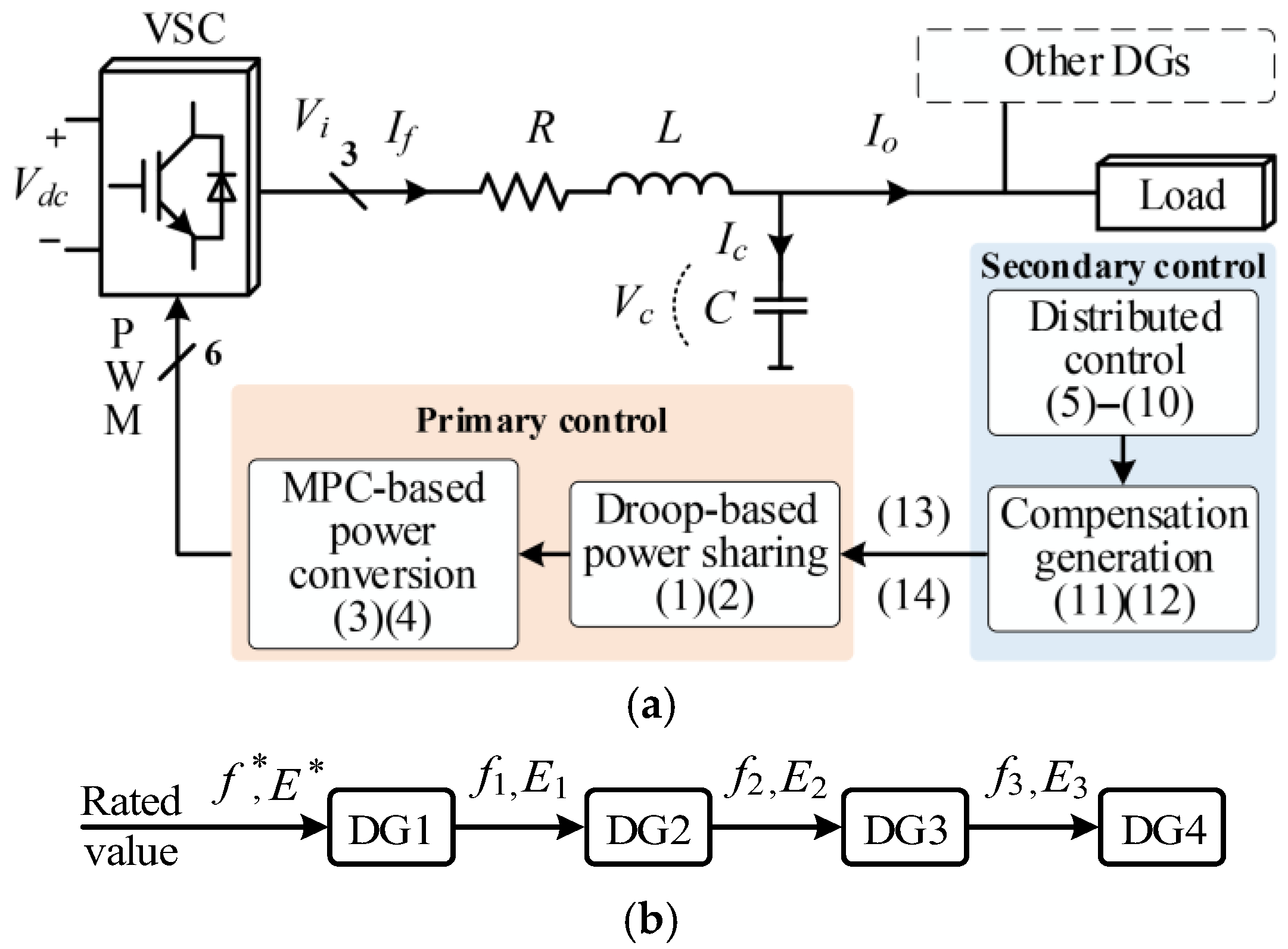
Figure 1. Diagram of the (a) PC and SC structures and connections in one DG. (b) Communication topology of the SC layer for four DGs.
Eng 06 00198 g001
Figure 2. Diagram of the (a) proposed WFPS-RC strategy and (b) FIL setup.
Eng 06 00198 g002
Figure 3. Comparison of system response curves when DG2 receives the frequency reference impacted by FDIA at 1 s: (a) No defense algorithms. (b) The proposed WFPS-RC strategy.
Eng 06 00198 g003
Figure 4. Comparison of system response curves when DG2 receives the voltage reference impacted by FDIA at 1 s: (a) No defense algorithms. (b) The proposed WFPS-RC strategy.
Eng 06 00198 g004
Figure 5. Comparison of system response curves when DG2 receives the frequency and voltage references both impacted by FDIA at 1 s: (a) No defense algorithms. (b) The proposed WFPS-RC strategy.
Eng 06 00198 g005
Figure 6. Comparison of system response curves when DG2 to DG4 all receive the frequency and voltage references both impacted by FDIA at 1 s: (a) No defense algorithms. (b) The proposed WFPS-RC strategy.
Eng 06 00198 g006
Figure 7. System performance when activating the VCCL at 7 s and when the following DG receives the frequency and voltage references both impacted by FDIA at 1 s: (a) DG2. (b) DG2–DG4.
Eng 06 00198 g007
Figure 8. System performance when FDIA occurs at 1 s and lasts for 1 s before SC removal using the proposed WFPS-RC strategy: (a) without the VCCL, (b) with the VCCL applied concurrently.
Eng 06 00198 g008
Figure 9. System performance with FIL implementation.
Eng 06 00198 g009
Disclaimer/Publisher’s Note: The statements, opinions and data contained in all publications are solely those of the individual author(s) and contributor(s) and not of MDPI and/or the editor(s). MDPI and/or the editor(s) disclaim responsibility for any injury to people or property resulting from any ideas, methods, instructions or products referred to in the content.