1. Introduction
During operation across the entire flight envelope, an aero-engine undergoes multiple transient processes, including start-up, acceleration, deceleration, afterburner engagement, and disengagement, as well as thrust vectoring. These transitions involve the rotor tip speed passing through transonic regimes. The parameters during these transient states directly reflect the performance of both the engine and its control system. Failures such as surge and flameout frequently occur during transients [
1,
2]. Moreover, the operating conditions of components that are critical to engine performance and service life—such as structural integrity, seal clearances, and blade tip and inter-blade gaps—are all influenced by changes in rotor dynamics and aerodynamic performance during these non-steady-state processes [
3].
To enhance performance and increase the thrust-to-weight ratio, it is common practice to reduce the clearance between the rotating and stationary components [
4,
5]. However, this reduction in clearance significantly increases the risk of rotor–stator rubbing incidents, which can lead to rotor imbalance, shaft fracture, or, in severe cases, complete mechanical seizure. A widely adopted solution in modern advanced aero-engines is the application of abradable seal coatings in critical regions of the flow path [
6,
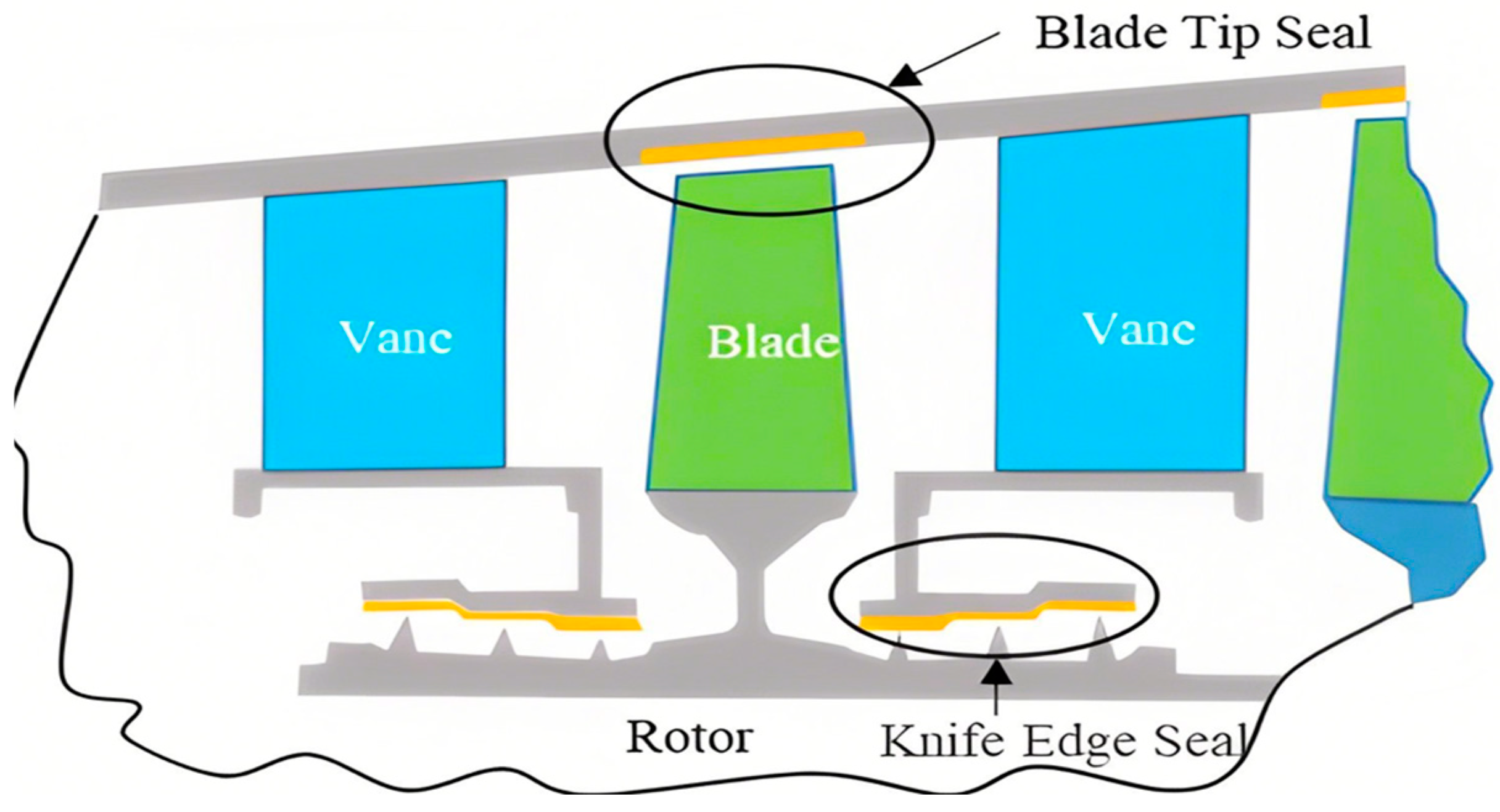
7]. These coatings are designed to come into contact with the blades during transient-state rubbing events, thereby preventing blade wear while maintaining minimal flow path clearances to improve engine performance. The typical application of abradable seal coatings in an aero-engine is illustrated in
Figure 1.
Improvements in aero-engine performance have resulted in increasingly high linear velocities at blade tips and elevated service temperatures, among other indicators. Consequently, the comprehensive performance requirements for coatings have become more stringent. The abradability of sealing materials is closely correlated with operating conditions, which presents challenges for effective evaluation through conventional rubbing and wear tests. In 2014, the Federal Aviation Administration (FAA) stated in the FAR 33.15 support document AC 33-11 that coatings need to be verified for compliance under test conditions analogous to those of the operating environment [
8,
9,
10]. CCAR33.63 stipulates that “each type of engine design …… throughout its stated flight envelope …… shall not result in excessive stress on any component of the engine due to vibration” [
11]. The Civil Aviation Administration of China (CAAC) also explicitly states in the advisory circular on aero-engine validation that “the applicant should demonstrate by analysis, test, or experience that the fan casing and fan rotor are insensitive to rotor-casing interactions and that there are no conditions that would lead to the occurrence of such phenomena.” [
12]. Therefore, the rubbing dynamic properties of the rotor–stator rubbing coupling and the abradable properties of the sealing coatings are essential subjects that must be addressed for engine development. Furthermore, these properties must be assessed using experimental devices that closely simulate the service conditions of the engine prior to installation.
Enhancing the performance of aero-engines results in increasingly higher blade tip speeds and operating temperatures, which pose more stringent demands on the comprehensive performance of abradable seal coatings. The abradability of sealing materials is closely related to operating conditions, so it is difficult to effectively evaluate them using conventional friction and wear tests. The FAA’s Advisory Circular AC33-11, issued in support of FAR 33.15 in 2014, states that coatings must undergo conformity verification under test conditions that closely resemble the actual service environment [
8]. Similarly, CCAR 33.63 stipulates that “the design of each engine … throughout the declared flight envelope … must not result in excessive stress on any engine component due to vibration” [
9]. The Civil Aviation Administration of China (CAAC) also emphasizes in its engine certification advisory circular that “the applicant shall demonstrate through analysis, testing, or experience that the fan case and rotor are not sensitive to rotor-to-case interaction, and that conditions leading to such interaction do not exist” [
10]. Therefore, the coupled rotor–stator rubbing dynamics and the abradability performance of seal coatings are critical research topics in engine development. Before entering service, such coatings must be evaluated using test rigs that simulate engine-like operational conditions.
In the past half century or so, scholars have carried out a great deal of research around the rubbing problems. A systematic summary of relevant theoretical advances has been provided. For example, Muszynska [
13] reviewed the research work on the modeling of rotor–stator rubbing and rotor response mechanisms before 1989. Jiang Jun et al. [
14] categorized the local and system models of rubbing in the theoretical studies from the viewpoint of dynamics and control and summarized the research results on the nonlinear response of rubbing. Ma et al. [
15,
16] reviewed the research on the blade-casing rubbing-induced dynamic behaviors and emphasized the modeling of the casing coatings, the wear behavior, and the effect on the overall vibration characteristics of the rotor–stator system.
Overall, there exists a large body of literature addressing rotor–stator rubbing in aero-engines, encompassing a wide range of research perspectives and emphases. However, most existing studies primarily focus on elucidating the damage mechanisms of rubbing from the standpoint of nonlinear dynamics or on the development of rubbing force models. While some publications discuss the experimental validation of rubbing behavior, they typically present only test results, with relatively limited attention given to the design and development of test rigs that accurately replicate real engine operating conditions for rotor–stator rubbing assessments.
This paper presents the design and evaluation of a transonic rotor–stator rubbing test rig developed to investigate and analyze rubbing and wear phenomena relevant to aero-engines. The structure of the paper is organized as follows: following the introduction,
Section 2 describes the overall structure of the rotor–stator rubbing test rig.
Section 3 focuses on the design and analysis of the transonic rotor system.
Section 4 details the design and analysis of the rubbing feed system, while
Section 5 covers the design and analysis of the rubbing measurement system.
Section 6 discusses the design of the heating system.
Section 7 presents the testing and experimental validation of the rotor–stator rubbing test system. Finally,
Section 8 summarizes the main conclusions.
4. The Design and Analysis of the Rubbing Feeding System
The primary function of the rubbing feed-in system is to achieve precise control of the rotor–stator clearance and intrusion depth. Rubbing occurs when the relative radial displacement between the rotor and stator exceeds the predefined clearance. A key characteristic of this mechanism is the occurrence of high-speed rotor–stator rubbing accompanied by a controlled radial feed-in motion at a certain rate. This feed rate can be regarded as the radial vibration velocity of the rotor shaft. In rubbing wear tests, to simulate the actual material removal behavior in aero-engines, the single-pass wear depth produced by a blade scraping the coating is used as a modeling variable. The single-pass wear depth can be determined based on the blade count, blade tip diameter, rotational speed, and radial vibration amplitude. Subsequently, the feed rate under simulated wear conditions can be calculated using the single-pass wear depth, simulated blade pitch circle diameter, blade tangential speed, and the number of simulated blades.
To achieve micron-level precision and stable feed rates, three primary types of precision mechanical feed drive systems are commonly used: (1) stepper motor + ball screw + precision linear guideway; (2) servo motor + ball screw + precision linear guideway; and (3) linear motor + precision linear guideway [
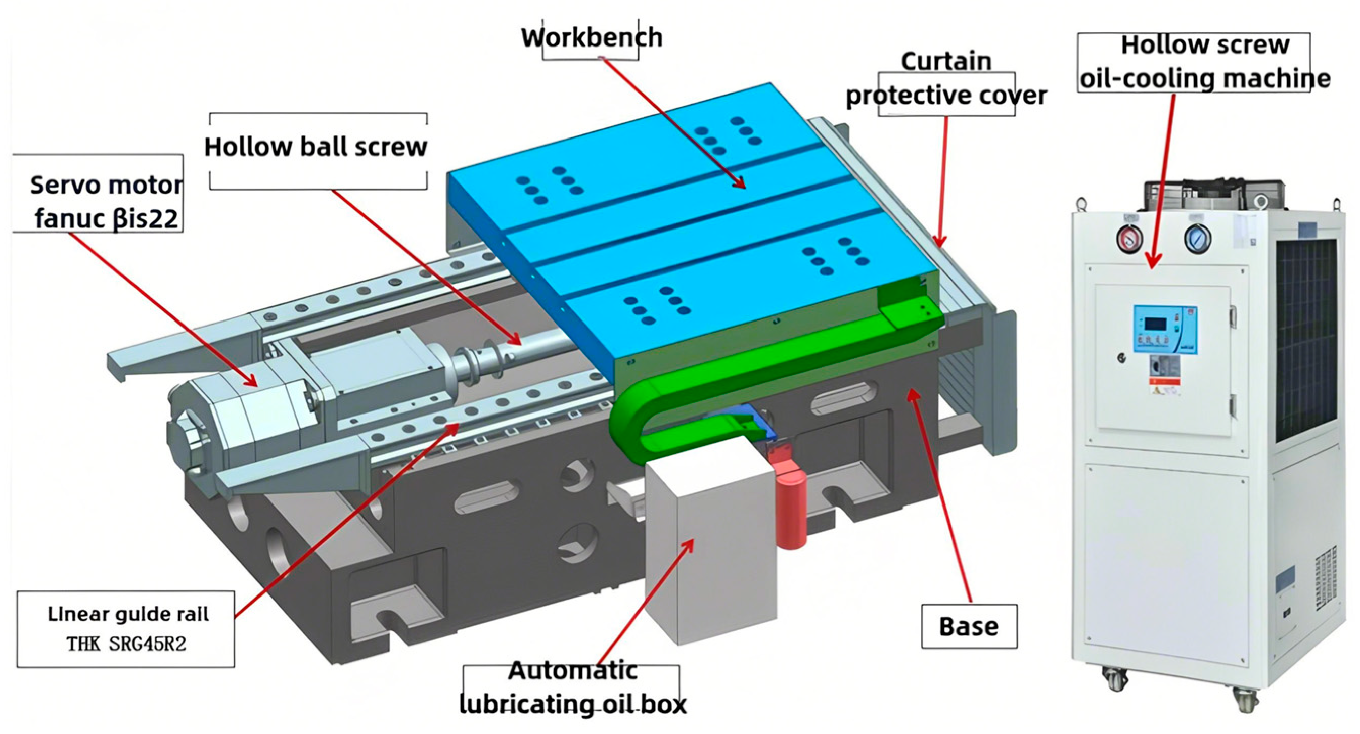
23]. The first two configurations are widely applied in high-precision machine tools and have reached a high level of technical maturity. The third option, while offering high precision, is less common due to its complex control system and significantly higher cost. To meet the uniform wear depth requirement for each blade pass, the system must maintain ultra-low feed rates with high stability—specifically, a stable feed rate of 2 μm/s. As stepper motors exhibit limitations in speed control stability at such low velocities, a “servo motor + ball screw + precision linear guideway” architecture was selected. In this configuration, a servo motor serves as the power source, driving a precision ball screw stage to achieve highly stable, micron-level low-speed feed motion. The complete feed-in system consists of a servo motor, linear guideways, a ball screw, a working platform, a lubrication tank, and an oil chiller, as shown in
Figure 13.
Table 2 summarizes the feed system test results. By employing a high gear-ratio precision planetary gearbox, the servo motor generates stable ultra-low-speed rotational motion, which is converted into linear motion by the ball screw mechanism. Experimental validation confirmed that the feed system can reliably achieve a feed rate of 2 μm/s with high stability, fully meeting the requirements of rubbing wear simulation.
5. Design and Analysis of the Rubbing Test System
5.1. Design of the Rubbing Test System
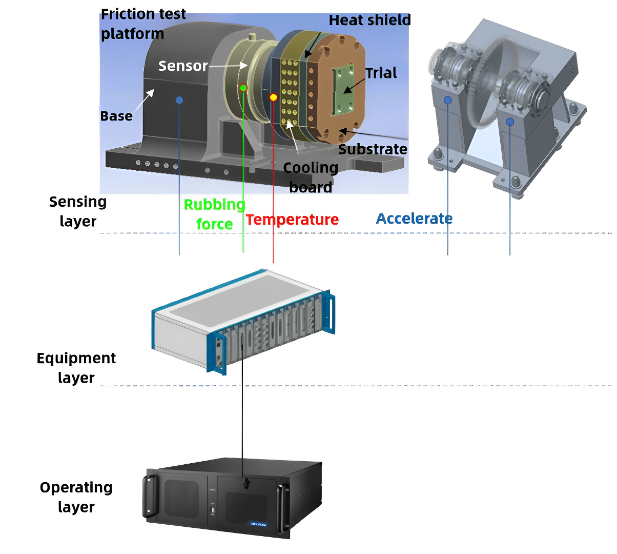
The overall layout of the rubbing test platform is shown in
Figure 14. The platform integrates multiple components, including the coating specimen, substrate, thermal insulation plate, cooling plate, force sensor, and base, to form a comprehensive rubbing force measurement system. Driven by the feed-in mechanism, the specimen is mounted on the substrate. A thermal insulation layer and a cooling plate are arranged between the substrate and the force sensor to ensure that the sensor operates within its allowable temperature range. During the rubbing process, the force sensor provides real-time measurements of the contact forces between the rotating blade and the specimen, enabling the accurate monitoring of rubbing dynamics.
According to the maximum rotor speed n
max = 12,500 r/min, it can be obtained that, when the single blade rubbing, the highest rubbing force fundamental frequency is
Due to the integration of the sensor and its mounting structures, the natural frequency of the assembled rubbing force measurement platform is significantly lower than that of the sensor alone. To minimize the risk of base resonance, the first-order natural frequency of the platform is required to be at least four times higher than the fundamental frequency of the rubbing force. Accordingly, the platform’s first natural frequency must not be lower than 832 Hz. Given the impulsive nature of rubbing forces and their broad frequency content, the measurement bandwidth must cover at least ten times the fundamental frequency of the rubbing force—i.e., at least 2083.3 Hz—to ensure accurate and reliable force acquisition. Although high-frequency components may exceed the platform’s first natural frequency, their energy is relatively low, and thus they are not expected to induce significant vibrations in the structure.
The natural frequency of the force measurement platform is designed to be 1.5 times greater than the required measurement bandwidth, with consideration given to the influence of specimen fixtures and other structural components on the platform’s dynamic characteristics. Based on this, the rubbing force sensor was required to have a natural frequency exceeding 4 kHz, with a minimum longitudinal measurement range of 10 kN and a transverse range of no less than 5 kN. According to these specifications, the triaxial force sensor model 9397C from Kistler which is made in Winterthur Switzerland was selected to meet the demands of the rubbing test system.
Upon completion of the mechanical construction and sensor integration of the test platform, an industrial PC was employed as the host computer to run both the data acquisition and signal analysis software. The data acquisition module performs fundamental functions such as sampling control, real-time data display, and storage. To investigate the rubbing mechanism and rotor dynamic characteristics, the rubbing force signals must undergo in-depth processing. Therefore, a dedicated data analysis module is utilized to perform filtering, statistical analysis, frequency-domain analysis, and time–frequency analysis of the acquired rubbing force signals. Furthermore, the measured rubbing force data are fed back into the control system in real time. Based on this feedback, the micro-feed mechanism is regulated accordingly, enabling the precise control of the rubbing process and ensuring the accurate simulation of rubbing behavior during testing.
5.2. Dynamic Characteristics Analysis of the Rubbing Test System
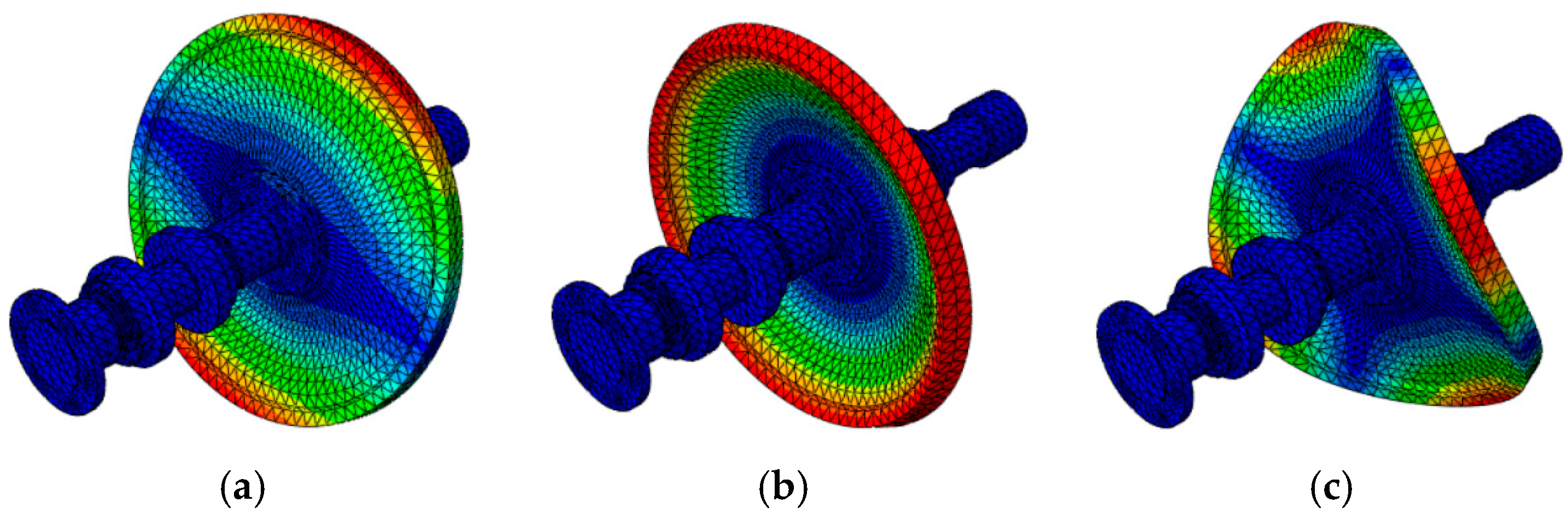
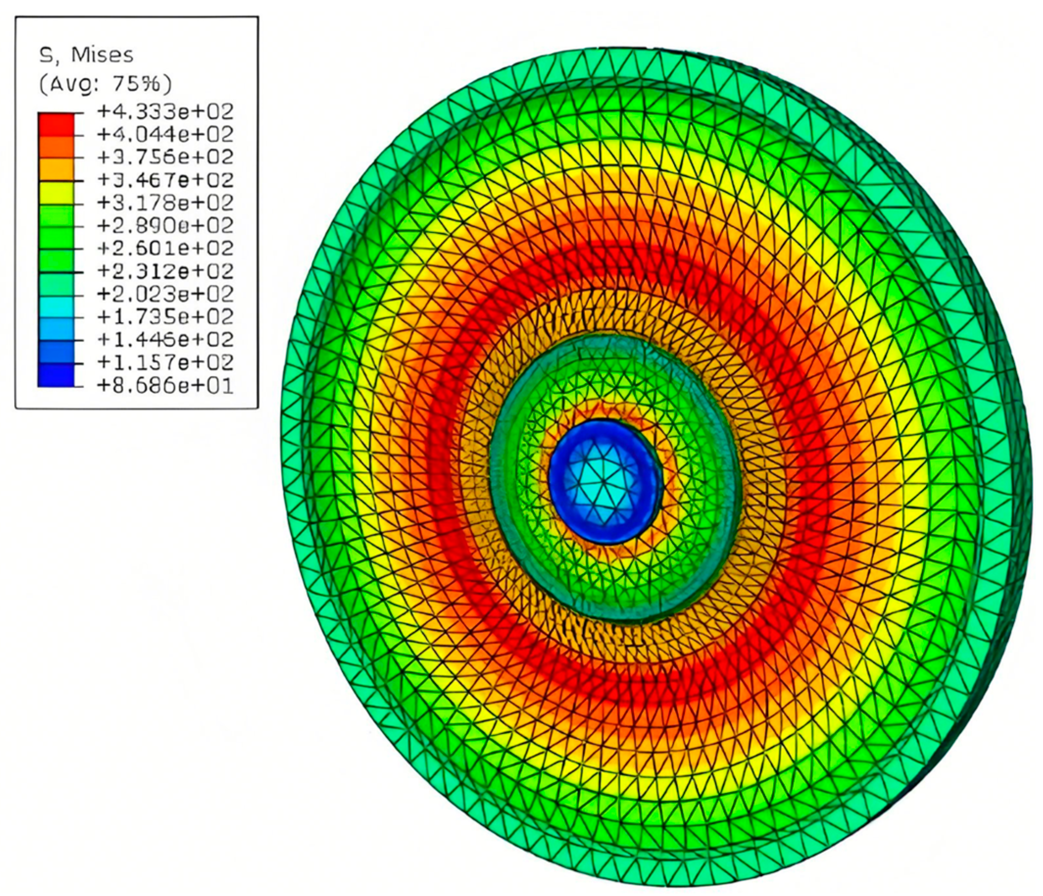
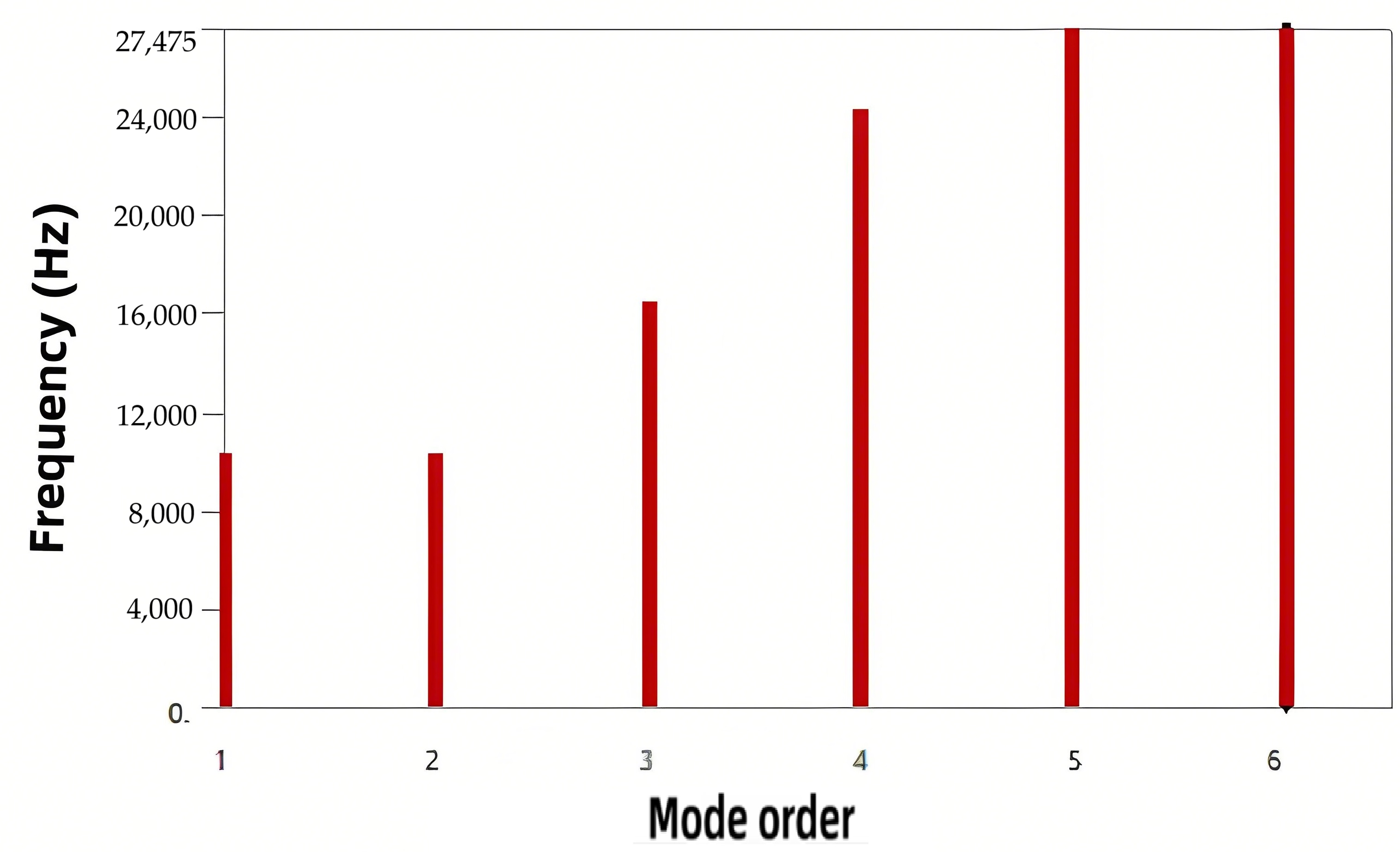
Since the force sensor is an assembly with unknown material properties, it is initially modeled as a single equivalent component based on its natural frequency. A rigid constraint is applied to the sensor’s bottom surface. During finite element modal analysis, the material properties of the equivalent model are iteratively adjusted until its natural frequency closely matches the actual measured value. The modal analysis results of the sensor are shown in
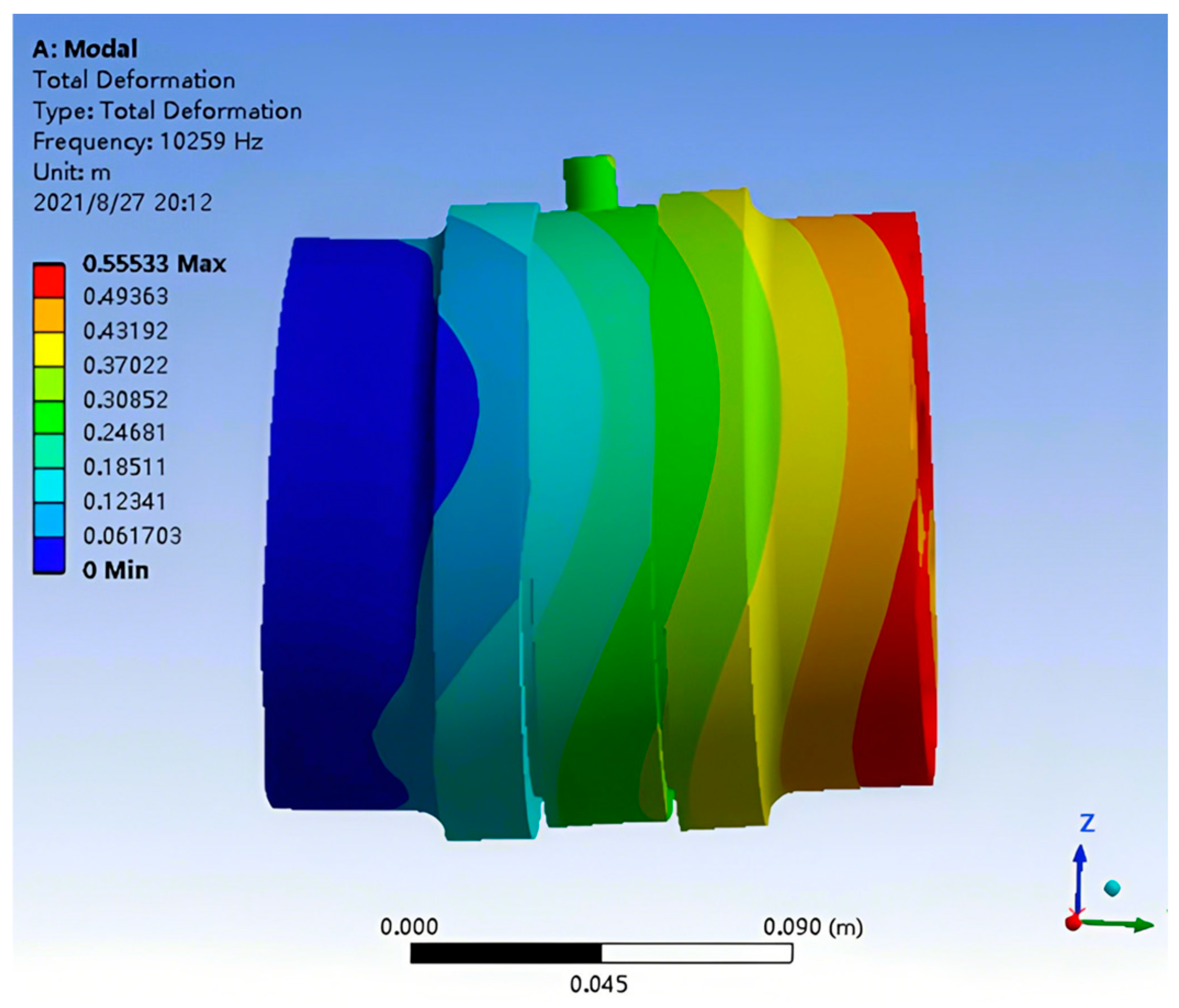
Figure 15, with the first-mode natural frequency calculated as 10,259 Hz. The corresponding first-mode shape is presented in
Figure 16, which is in good agreement with the actual natural frequency of approximately 10.3 kHz.
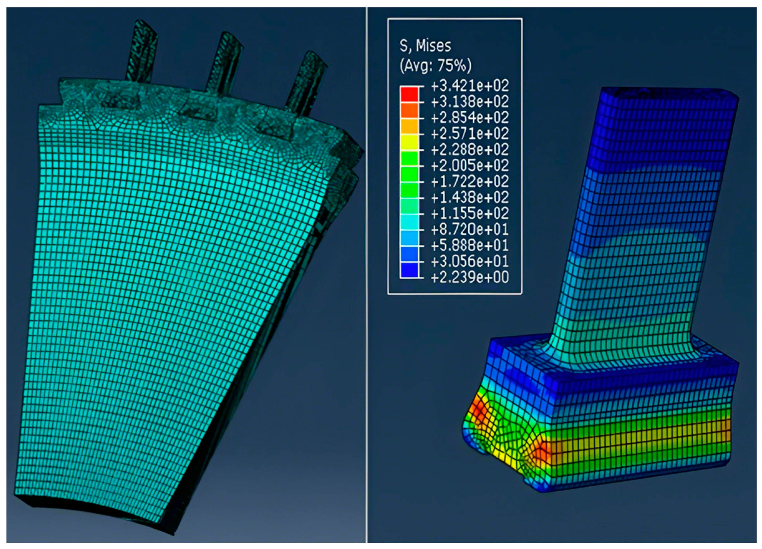
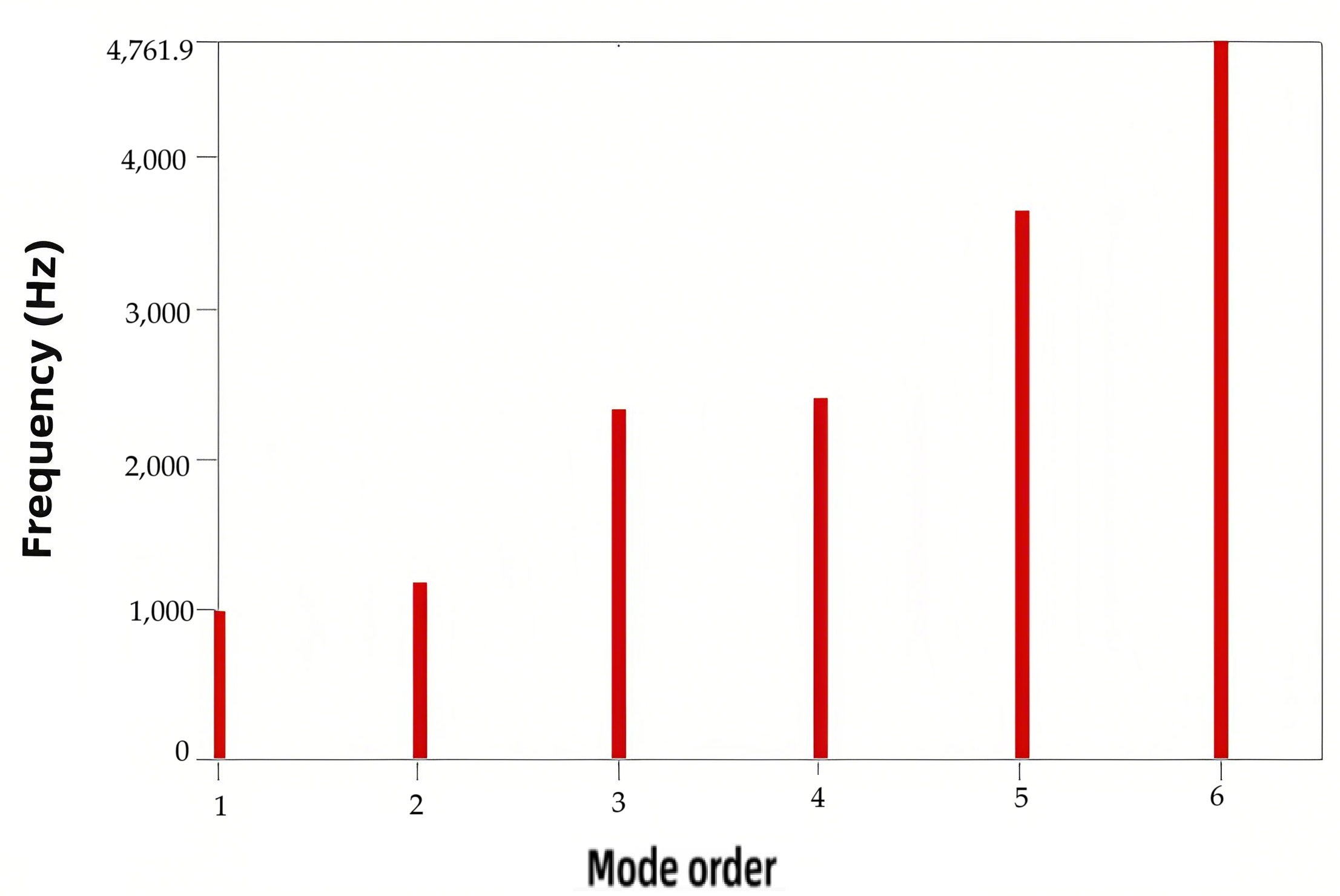
Subsequently, a dynamic characteristic analysis is conducted on the force measurement platform. The modal analysis results are shown in
Figure 17, indicating that the first-order natural frequency is 981.89 Hz. The corresponding mode shape is illustrated in
Figure 18. Since the first natural frequency exceeds four times the fundamental frequency of the rubbing force, the platform meets the dynamic performance requirements for the rubbing force testing system.
5.3. Analysis of the Force Transmission Characteristics of the Rubbing Test System
Since the first-order natural frequency of the force measurement platform is lower than the bandwidth of the rubbing force, the high-frequency components of the rubbing force exceed the effective measurement range. Consequently, the rubbing force measured by the sensor will deviate from the actual force exerted by the blade on the specimen. This discrepancy is analyzed through transient dynamic simulation.
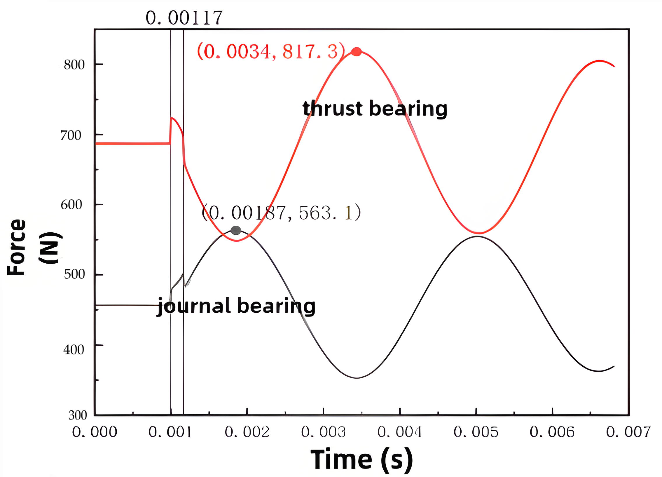
At the maximum rotational speed, the rubbing period is 4.8 ms, with the maximum rubbing length approximately 50 mm. The rubbing action duration accounts for about 3% of the rubbing period, approximately 0.15 ms. Transient impact dynamic simulations show the force on the sensor’s upper surface as depicted in
Figure 19, with a peak value of 7544 N. This corresponds to a rubbing force amplification factor of 7544/4500 = 1.68. When the rubbing depth decreases, the rubbing duration shortens, leading to a further reduction in the amplification factor. Thus, although the rubbing force is amplified, it remains within an acceptable range. In subsequent experiments, more accurate rubbing forces can be obtained through sensor sensitivity calibration and error compensation algorithms. The main approach involves correcting the force sensor response using the system’s transfer function between the excitation force and sensor output. This transfer function depends solely on the structural characteristics of the system and is independent of external factors such as the excitation or response signals. Excitation can be applied via a force hammer or shaker. During experimental calibration, the sampling frequency and number of sampling points for the rubbing force must be consistent with those used when determining the transfer function, ensuring the force sensor response and transfer function share the same bandwidth and frequency resolution. The sensor signal is first transformed into the frequency domain, then multiplied by the transfer function, and finally transformed back to the time domain to obtain the time-domain excitation force signal.
6. Rubbing Heating System Design
Based on the structure of the blade disk and the rubbing feed device in the experimental setup, two symmetrically arranged heating units are employed to apply thermal loads. Positioned between the two heating units is a turbine disk simulator. The heating units are mounted on specially designed support plates and are secured to the rubbing feed platform using bolts.
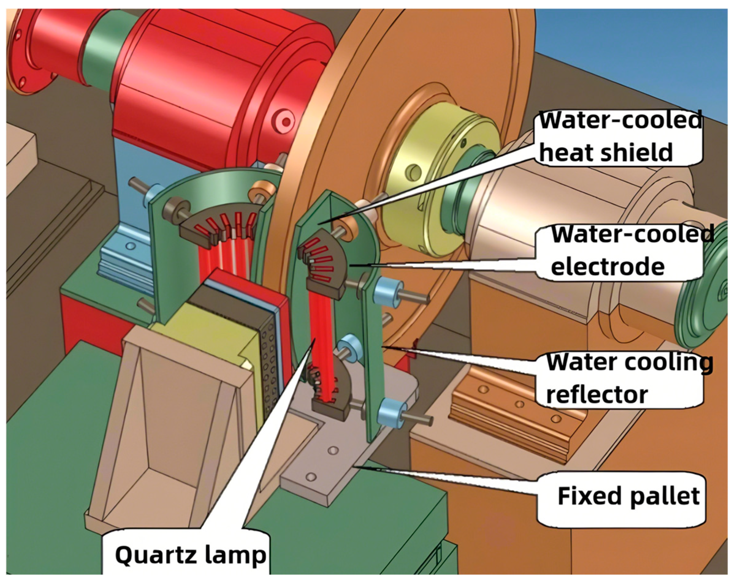
Each heating unit comprises quartz lamps, water-cooled electrodes, water-cooled reflectors, fixed support plates, and water-cooled thermal insulation plates, as illustrated in
Figure 20. The water-cooled reflector, thermal insulation plate, and fixed support plate form the main structural framework of the heating unit are also shown. The quartz lamps, serving as the heating elements, are fixed in a curved heating array by the water-cooled electrodes, which are insulated from the main framework by ceramic insulators. Each heating unit is equipped with five quartz lamps, each 220 mm in length, arranged with a spacing of 16 mm between adjacent lamps. Each lamp has a rated power of 2 kW and an effective heating length of 160 mm, sufficiently covering the heated surface of the specimen. The power density of the quartz lamp heating array is 801 kW/m
2. Assuming a thermal conversion efficiency of 50%, the heating array can deliver an effective heating capacity of 400 kW/m
2, meeting the requirement to achieve a maximum temperature of 1200 °C.
The heating system is powered by silicon-controlled rectifiers (IGBTs) and operates under closed-loop control. The control system adjusts the IGBT output voltage based on the temperature feedback from the heated surface and the setpoint command to achieve precise temperature regulation. Each heating unit has a total power of 10 kW, with two units providing a combined power of 20 kW. Considering the potential overvoltage conditions of the quartz lamps, two 25 kW IGBT power modules are employed to supply the heating system. All components’ water-cooling circuits use tap water without requiring dedicated piping or booster pumps.
Thermal insulation for the test specimen fixtures and the portion of the rubbing feed device exposed within the heating zone is provided by insulating needle mats. The turbine disk simulator is thermally insulated by water-cooled insulation plates integrated with the heating units. The heating elements are quartz lamps, each 310 mm in length and rated at 3.6 kW, with a total of 12 quartz lamps in the system. The flow guiding elements consist of four 90° brass circular rings featuring internal cooling channels, through which coolant is circulated via hollow threaded pipes. The fixing elements are made of high-temperature-resistant ceramics, with eight pairs used to secure the flow guiding elements. Additionally, two 90° cylindrical metal reflectors with polished mirror-finish inner surfaces are employed; these reflectors feature 22 mm diameter holes for mounting the fixing elements.
7. Debugging and Test Verification of Rotor Static Rubbing Experimental Device
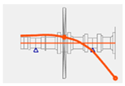
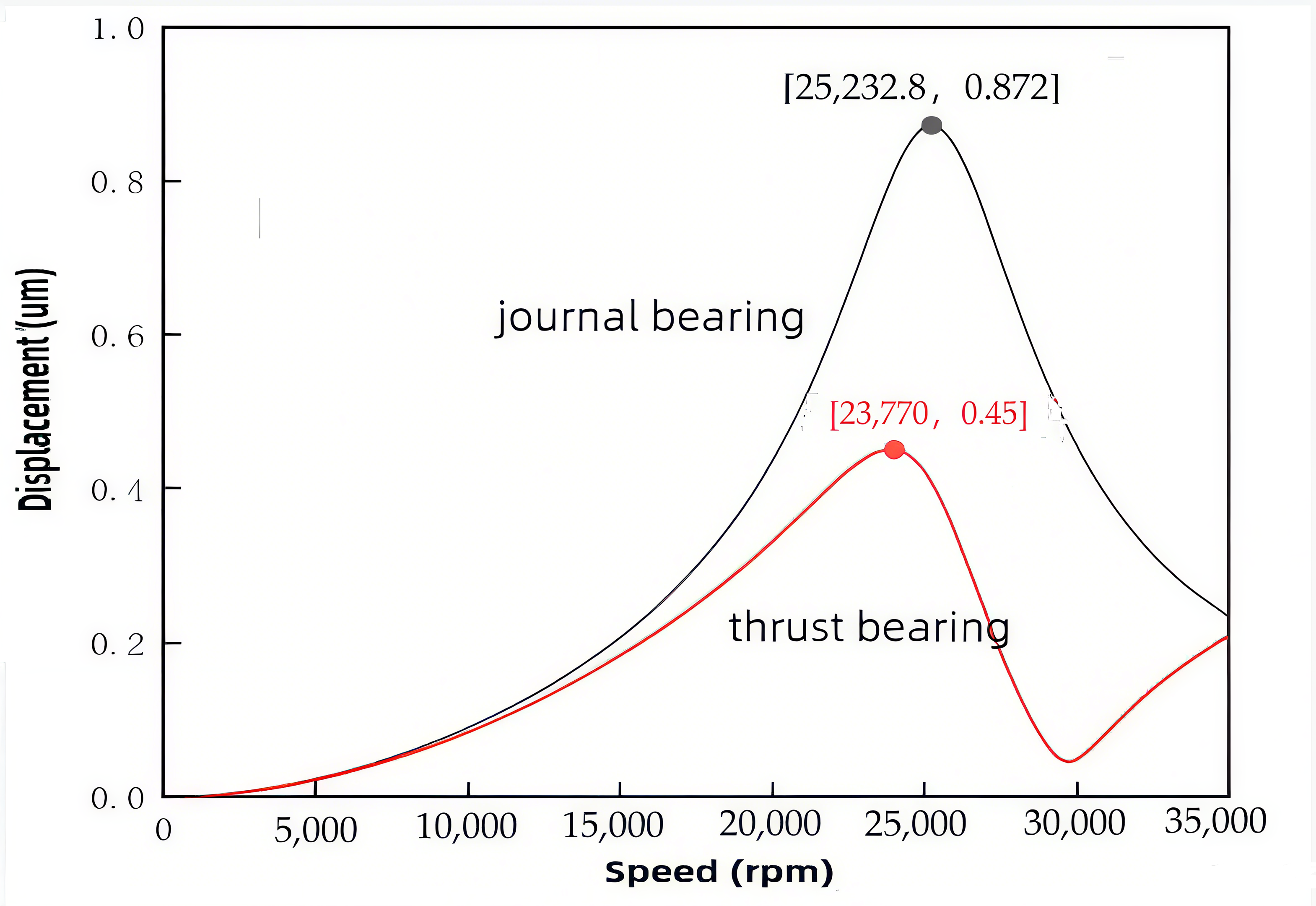
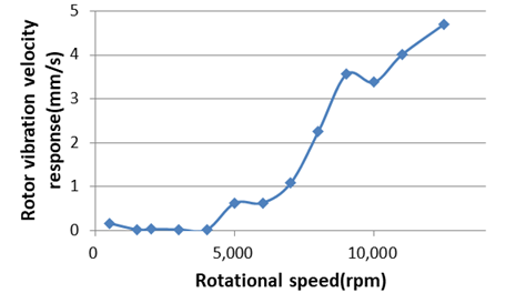
The purpose of the integrated commissioning of the high-speed rotating experimental rig is to verify whether the various subsystems work collaboratively to meet the required specifications, with a particular focus on assessing the key parameters of the transmission system. According to the rotor vibration level requirements, the vibration velocity alarm threshold for the rotor system is set at 7.1 mm/s, and the shutdown threshold at 11.2 mm/s. During commissioning, the rotor system was gradually accelerated, and no critical speed resonance points were detected throughout the speed range. When the rotational speed reached 12,500 rpm, the rotor vibration velocity response was 4.7 mm/s, as shown in
Figure 21, indicating stable system operation. After the test system was shut down, inspections were carried out on the installation condition and damage status of each component. All components were found to be securely installed without any looseness. Non-destructive inspections performed after disassembly revealed no damage.
Figure 22 shows the temperature measurements of the coating specimen during heating experiments using both an infrared thermometer and thermocouples. The temperature readings from the infrared thermometer are slightly higher than those from the thermocouples because the former measures the temperature at the heated surface of the coating specimen, whereas the latter measures the temperature of the underlying metal substrate. Due to thermal attenuation within the material, the temperature difference decreases gradually as the heating duration increases. The temperature curves indicate that the maximum temperature can reach up to 1200 °C and that stable heating is maintained throughout the test.
Based on the stable and reliable operation of the rotor system, blade-to-coated casing rubbing tests were conducted. The specific procedure was as follows: First, the single-step preliminary feed depth was adjusted until the force sensor detected a rubbing force signal, which was set as the contact zero position. The feed was then retracted to the initial position, and the rotor system was started and accelerated to the test speed. Subsequently, the feed system was gradually advanced to the preset gap value to achieve controlled rubbing between the blade and the coated casing.
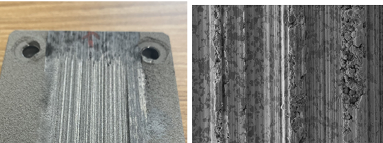
In the test, the blades are made of TC4 material, and the coating is an AC100 consumable coating with a thickness of 6 mm. Under the conditions of a blade tip speed of 425 m/s, a feed depth of 3 mm, and a feed rate of 50 μm/s, the morphology of the blade and coating after rubbing is shown in
Figure 23. The figure reveals a relatively smooth cutting zone and a rougher rubbing zone on the worn coating surface. The rough zone extends prominently along the rubbing direction, indicating severe wear in the corresponding blade tip rubbing area, with evident localized cracking and plastic deformation. In contrast, the relatively smooth cutting zone corresponds to a more intact portion of the blade tip, where wear is comparatively light.
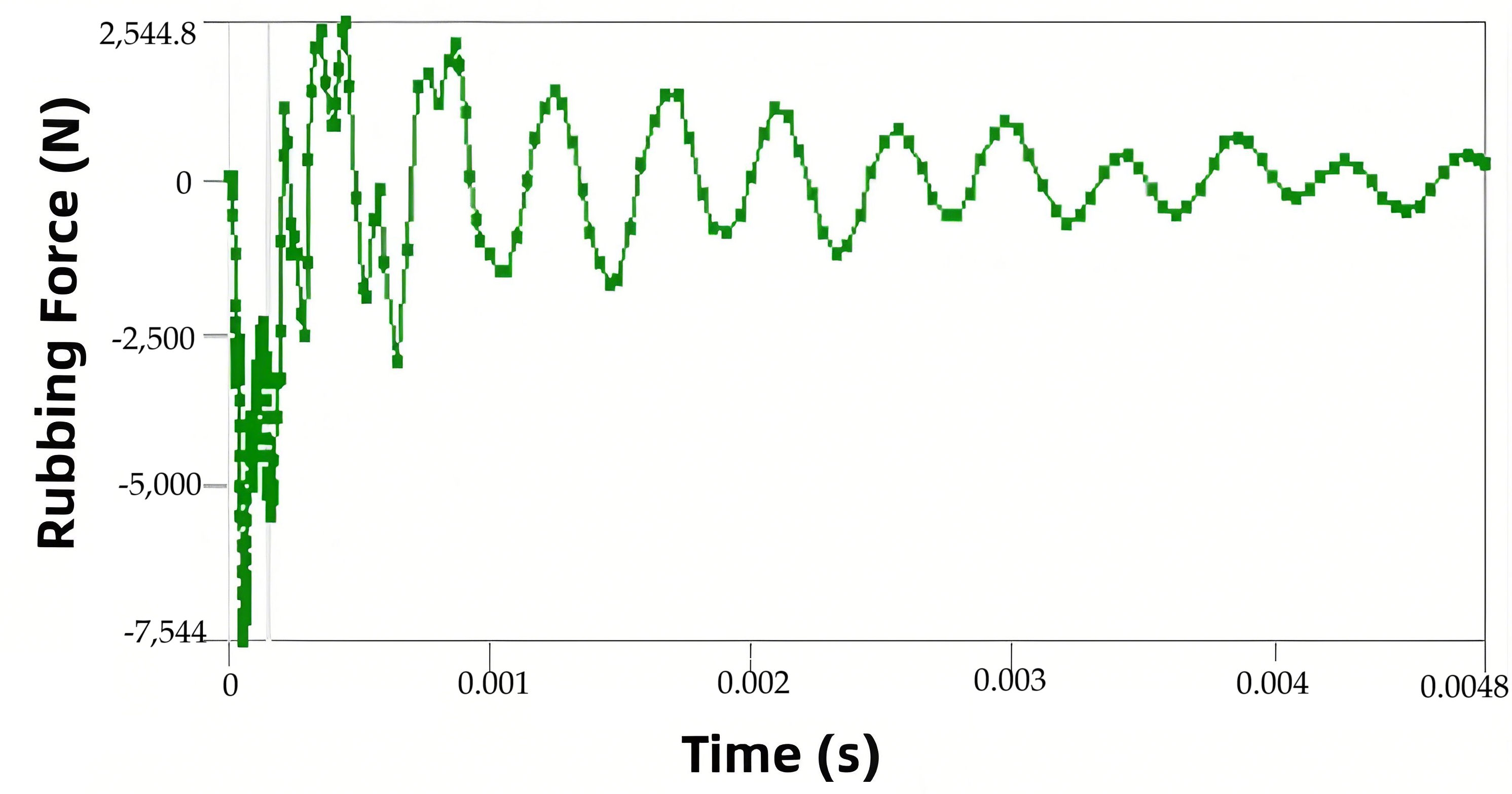
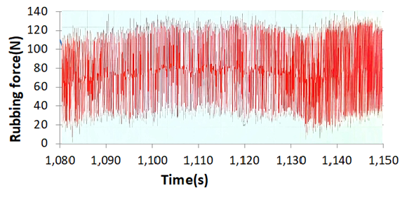
During the rubbing process, the rubbing force exhibits a periodic variation pattern, with a cycle consistent with the blade rotation period. At the moment of contact, the rubbing force experiences an instantaneous peak followed by a gradual decay. The rubbing force profile during the process is shown in
Figure 24. The peak value of the rubbing force reflects the magnitude of the force applied during the rubbing event, and the collected data demonstrate stability and repeatability.
Therefore, through performance testing of the experimental system, it is verified that the designed rubbing test system can accurately control key test parameters such as blade tip speed and feed rate, achieving the required technical specifications and functionalities. Moreover, the rubbing tests demonstrated that high-frequency rubbing forces occurring during high-speed rubbing can be effectively captured, confirming that the system’s testing capabilities meet the requirements for evaluating the wear performance of coatings.
Considering that in real engine environments, rotor–stator rubbing often occurs at multiple points or even circumferentially, the current system can be modified by redesigning the stator casing into an arc-shaped structure to achieve multi-point rubbing. However, for component-level testing under full-circumferential rubbing conditions, the feed system would need to be redesigned accordingly. This system primarily targets material-level assessment and verification tests that closely simulate actual engine operating conditions. Additionally, since the duration of the test is relatively short—thermal exposure time being within 10 min—the influence of the thermal environment on material properties is neglected. Nonetheless, the rotor–stator rubbing test does evaluate the thermal effects induced by the rubbing process.


