1. Introduction
Steel–concrete composite structures have become a cornerstone of modern construction, providing a superior means of combining the tensile strength and ductility of steel with the compressive stiffness and durability of concrete. This synergy results in structural systems that exhibit high strength-to-weight ratios, reduced deflection, and improved material efficiency compared to conventional reinforced concrete or steel-only systems. Initially, steel members were encased in concrete primarily for fire resistance; however, subsequent investigations revealed that this configuration significantly enhanced overall stiffness and load-bearing capacity, thereby forming the foundation for contemporary composite construction practices.
A major breakthrough in composite construction came in the 1950s with the introduction of headed stud shear connectors, which allow effective shear transfer between steel beams and concrete slabs. These connectors enable full or partial composite action, allowing both materials to behave as a single structural unit under bending and shear forces. The resulting improvement in flexural stiffness, strength, and ductility has driven widespread adoption of composite beams in buildings and bridges.
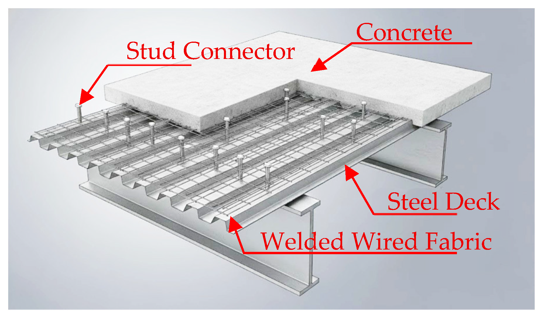
Modern composite floor systems typically comprise three essential components: a steel beam, a reinforced concrete slab, and mechanical shear connectors. The concrete slab may be cast as a solid section or over profiled steel decking, forming a composite slab system that integrates construction speed with structural efficiency. The typical arrangement is shown in
Figure 1, illustrating the key components and their interaction.
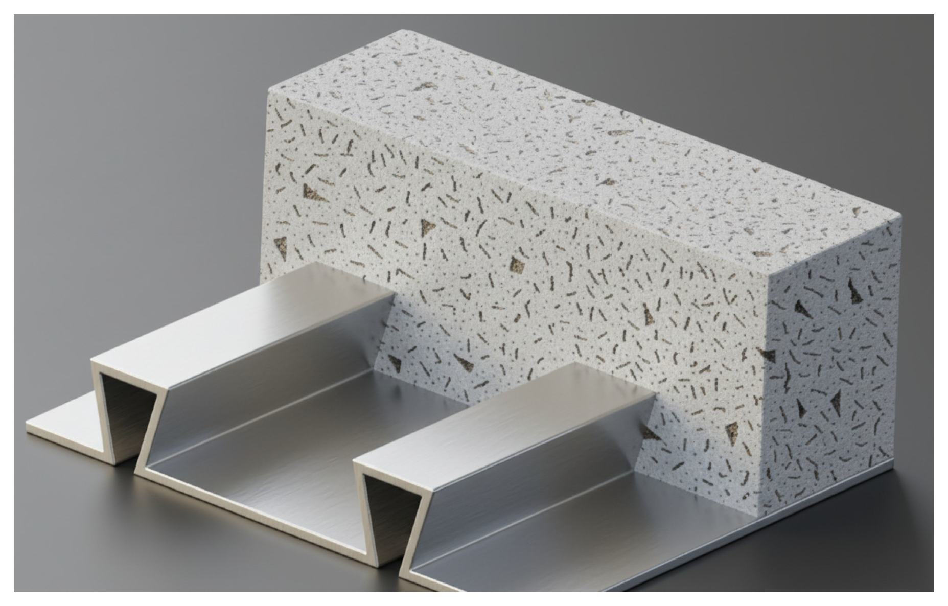
Corrugated or profiled steel decking is commonly used as permanent formwork during construction. It provides immediate support for wet concrete and construction loads without additional shoring, and once hardened, the deck acts compositely with the concrete slab to resist tensile stresses in the slab’s tension zone. The decking’s mechanical bond with concrete is enhanced by embossments or flute patterns on the steel surface, as illustrated in
Figure 2. This configuration improves shear transfer at the interface and increases flexural capacity while reducing self-weight and construction time.
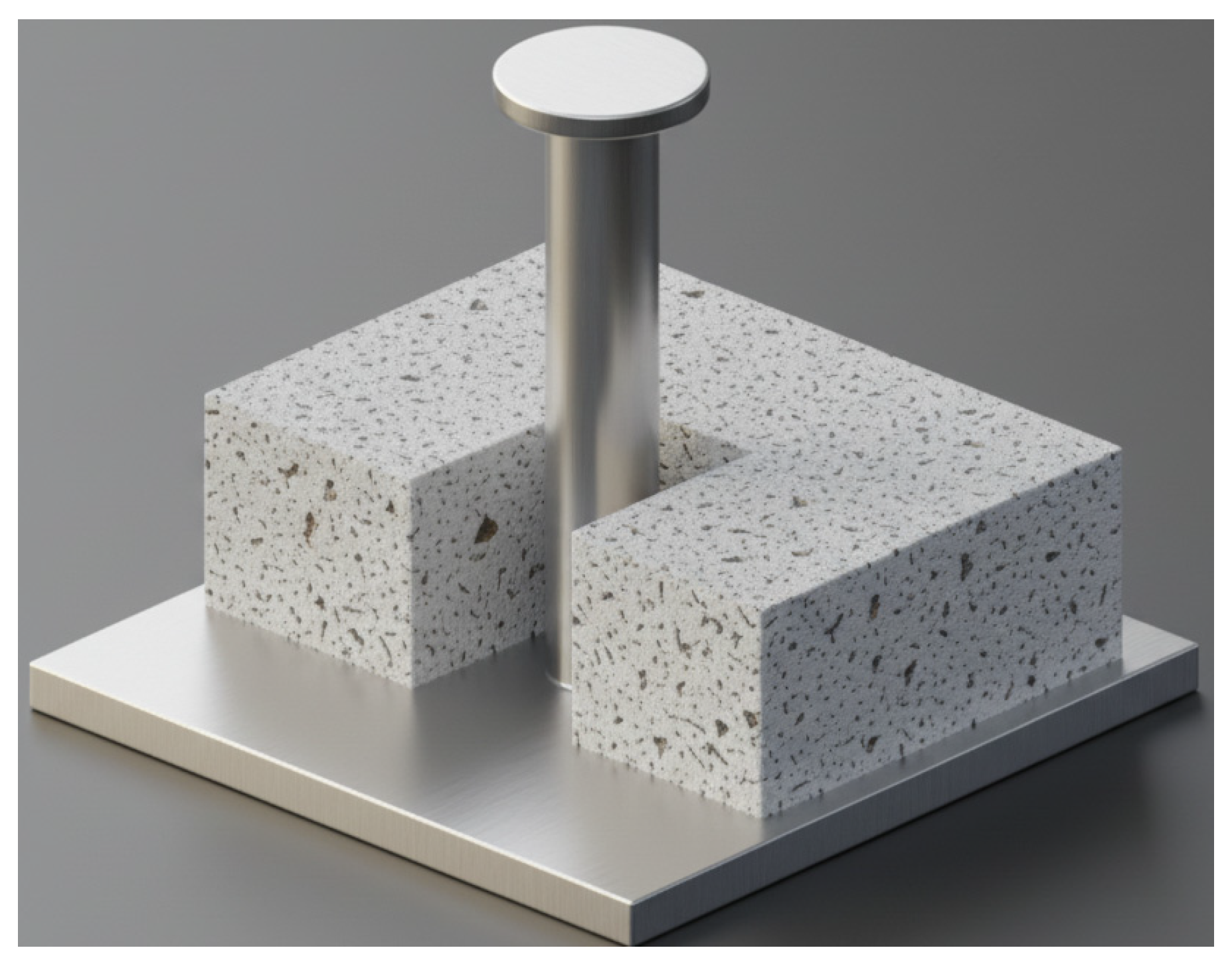
The integrity of the composite action is largely governed by the performance of shear connectors, among which the welded headed stud is the most widely used. These connectors, shown in
Figure 3, consist of a steel rod welded to the beam flange with a rounded head to provide anchorage in the concrete. Typical stud diameters range from 16 mm to 22 mm, and their height is generally at least 40 mm above the top of the steel deck to ensure full engagement. Headed studs are favored for their high strength, ease of installation, and consistent behavior under cyclic loading.
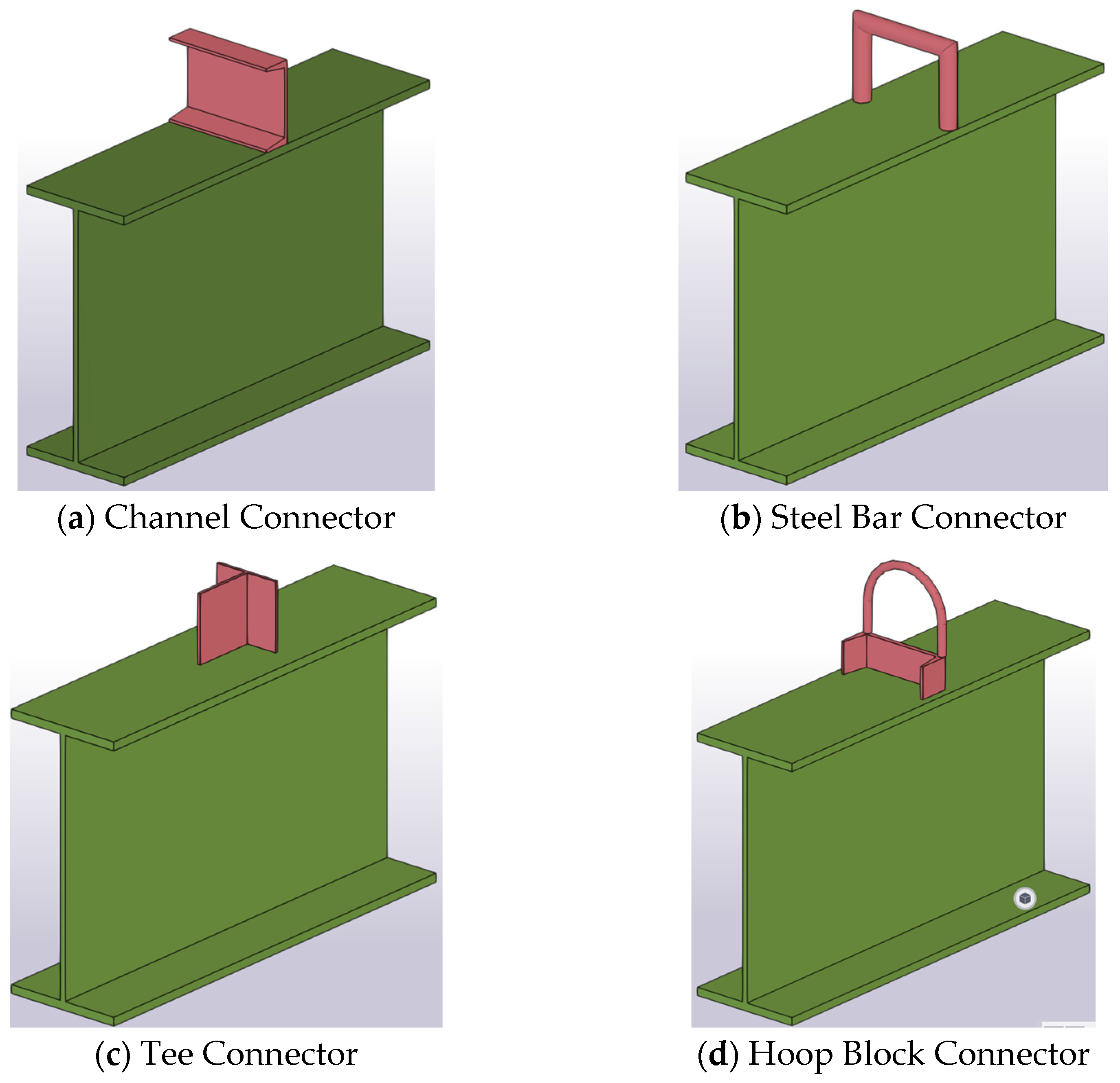
Experimental and analytical studies over several decades have investigated the shear behavior of connectors in composite systems. Alternative configurations—such as bar-with-hoop, tee-with-hoop, horseshoe, and channel-type connectors—have been proposed to enhance load transfer, as depicted in
Figure 4. Push-out and pull-out tests have been instrumental in quantifying connector performance and guiding design recommendations.
Research into composite beam behavior spans several decades. Johnson et al. [
4] conducted seminal work on continuous composite beams to assess the effects of cracking and transverse bending. Their study, comprising twenty beams tested under different configurations, revealed that transverse reinforcement at the bottom of the slab is essential unless consistent hogging (negative moment) is maintained. They emphasized the significance of reinforcement detailing in ensuring adequate moment resistance in both positive and negative bending regions. Extensive investigations on the performance of shear connectors in composite steel–concrete systems, particularly focusing on the influence of profiled steel sheeting, were conducted by Jayas and Hosain [
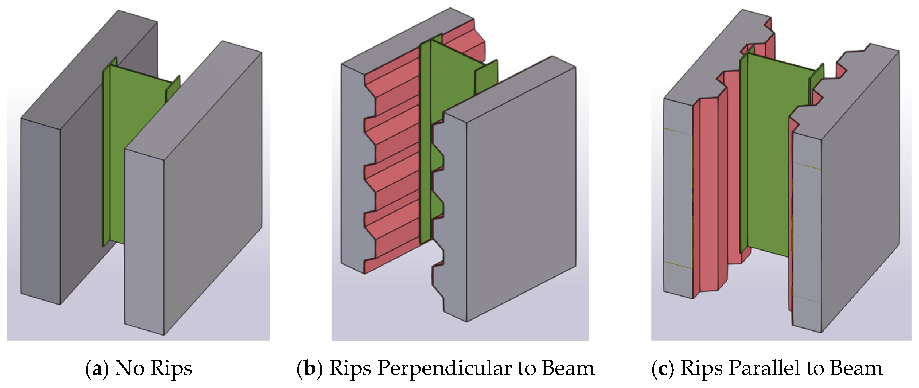
5]. They examined the behavior of headed stud connectors in composite beams with ribbed metal decking oriented both parallel and perpendicular to the steel beam. The study involved 18 full-scale push-out specimens and 4 pull-out specimens, as illustrated in
Figure 5. The primary experimental variables were the longitudinal spacing of the studs and the geometry of the metal deck ribs. Their findings indicated that a minimum stud spacing of six times the stud diameter is necessary to promote stud shearing rather than concrete failure in solid slabs or those with parallel ribs. In contrast, specimens with perpendicular decking experienced significant reductions in shear capacity—up to 40% and 50% for wide and narrow rib profiles, respectively.
In a similar effort, Lloyd and Wright [
6] carried out 42 through-deck push-out tests using headed shear studs embedded in trapezoidal profiled steel sheeting. They aimed to establish a standardized testing format and to assess the effects of practical construction variables such as slab width, depth, and reinforcement arrangement. The findings highlighted the sensitivity of shear connector performance to these factors and contributed to the development of more reliable design and testing practices for composite floor systems.
Further modeling and experimental efforts were undertaken by Dabaon [
7], who developed a mathematical approach to assess deformation in the negative bending region using ductile, nonrigid shear connectors. Validated through full-scale testing, his work demonstrated that low levels of shear connection can be advantageous in both positive and negative moment regions by improving ductility without compromising overall strength. Building on this concept, Manfredi at al. [
8] proposed a one-dimensional analytical model to evaluate composite beam behavior under negative bending, explicitly accounting for interactions between steel, concrete, and shear connectors. Their generalized moment–curvature relationship proved effective for assessing rotational capacity and quantifying the influence of reinforcing steel ductility on overall flexural performance.
Subsequent investigations by Dabaon [
9] expanded the understanding of composite beam response by examining the influence of effective slab width in regions of hogging moment. Results from his full-scale tests indicated that the effective width significantly affects the moment capacity, reinforcing its critical role in design provisions. To complement experimental findings, Liang et al. [
10] developed advanced finite element (FE) models to study the combined effects of concrete slab participation and shear connection level on the vertical shear strength and moment, shear interaction of continuous composite beams [
10]. Validated against the experimental results of Ansourian [
11], Liang’s 3D FE model was shown to conservatively predict the ultimate strength of composite beams, highlighting that concrete slabs enhance vertical shear resistance, which increases with greater shear connection ratios.
Parallel advancements in numerical modeling were made by El-Shihy et al. [
12], who introduced a refined FE model capable of simulating shear connector slip and uplift in both positive and negative bending regions. Their simulations closely matched experimental results, providing strong validation for nonlinear modeling of partial interaction effects. Expanding upon this, Loh et al. [
13] conducted extensive experiments on eight beams under static and cyclic loading, demonstrating that partial shear connection can maintain ultimate load capacity while substantially increasing ductility. A complementary analytical study by Loh et al. [
14] incorporated slip and partial interaction into their models, confirming that beams with partial connections experience minimal strength reduction yet exhibit significantly improved ductile behavior.
Further refinement of composite beam modeling was undertaken by Nie et al. [
15], who developed a method to compute equivalent stiffness while accounting for shear slip effects. Their results showed that closer stud spacing and improved deck geometry enhance both stiffness and flexural capacity. Similarly, Sousa Jr & da Silva [
16] introduced a nonlinear FE formulation using interface elements to model interlayer slip in multilayer composite beams, offering a more realistic representation of load transfer mechanisms. Experimental studies by Marimuthu et al. [
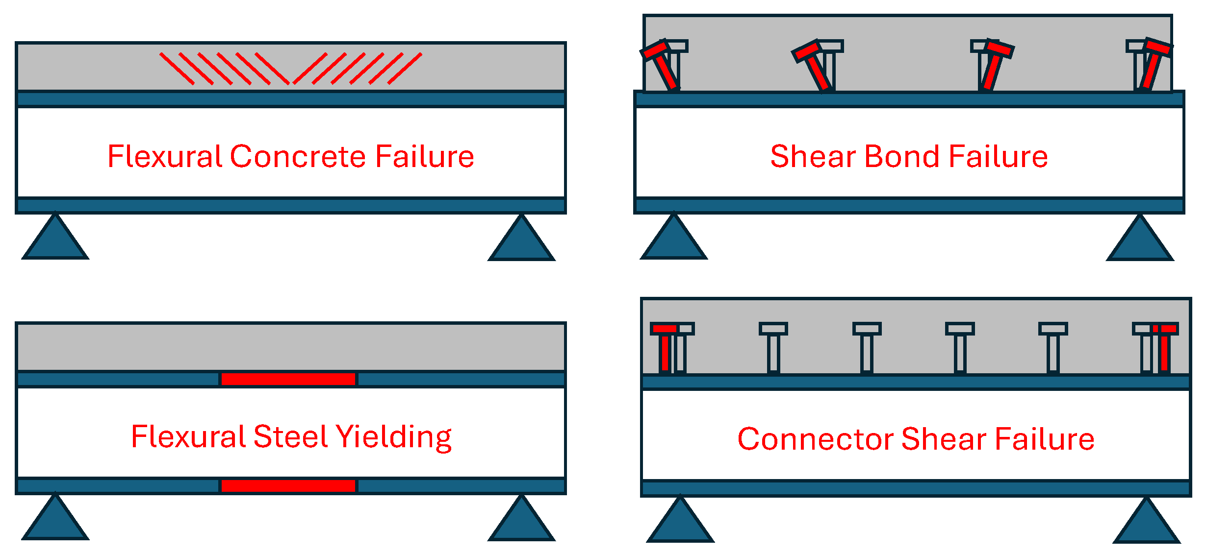
17] on beams with embossed steel decks demonstrated that failure modes transition from shear bond failure at shorter spans to flexural failure at longer spans, emphasizing the interaction between span length and shear connector behavior.
Comprehensive 3D FE modeling by Queiroz et al. [
18] further elucidated the impact of material properties and connection degree on composite beam behavior. Their parametric studies revealed that concrete compressive strength and web yield stress are dominant factors influencing system stiffness, ultimate moment capacity, and load–deflection characteristics. Extending these findings, Nie et al. [
19] performed three series of experiments on thirteen beams under positive and negative bending to examine the performance of partial shear connections in continuous spans. Their results confirmed that partial interaction is effective across various bending regions when adequate reinforcement detailing is provided.
Addressing serviceability issues, Fahmy and Abu-Amra [
20] used 3D FE analysis to investigate longitudinal cracking in ribbed metal deck slabs. They concluded that loading type, deck geometry, transverse reinforcement ratio, and shear connection degree are key parameters influencing crack formation and propagation. Similarly, Ernst et al. [
21] performed 36 push-out tests using a flexible single-sided rig and observed that trapezoidal decking with wide ribs tends to trigger premature concrete-related failures, compromising strength and ductility, making such systems unsuitable for plastic design applications.
To quantify shear resistance in bridge applications, Joeng et al. [
22] utilized the
m,
k method through combined push-out and flexural testing of ribbed connectors. Their results underscored the importance of long shear spans to minimize the influence of normal interface forces, ensuring consistency between pure and surface-induced shear resistance. Similarly, Nguyen et al. [
23] developed a nonlinear mixed FE model incorporating realistic material behavior, including tension stiffening, to simulate continuous composite beams with discrete connectors. Their model accurately captured experimental responses and highlighted the influence of span length and shear connection degree on ductility and load capacity.
Innovative connection systems were also explored by Tahir et al. [
24], who proposed a high-strength fastening pin connector as an alternative to conventional welded studs. Push-off tests showed that failure typically occurred within the pins, suggesting that improvements in penetration depth and base plate stiffness could substantially enhance strength and ductility. Lastly, El-Shihy et al. [
25] extended earlier research by combining experimental and numerical methods to study composite beams with corrugated steel sheets subjected to torsion, shear, and bending. Their nonlinear FE model, which accounted for partial interaction and complex loading, accurately predicted load–lection behavior and offered valuable insights into torsional and shear performance under realistic service conditions.
Recent advancements in composite structural systems have extended beyond conventional beams and slabs to encompass steel–concrete composite (SCC) walls and concrete-filled steel tubular (CFST) members. A critical area of contemporary investigation involves the lateral stability of coupled SCC systems, as explored by Wang et al. [
26]. Their work focused on the lateral load-carrying behavior of coupled SCC wall-frame structures, which consist of concrete-filled steel tubular (CFST) columns, composite beams, and composite walls. Through extensive experimental and numerical analysis, they demonstrated that the inclusion of the composite wall significantly increases the overall lateral load-carrying capacity of the structure. Crucially, they found that enhancements were most effective when increasing the thickness of the steel tubes and wall faceplates, or the wall width, while increasing the steel beam stiffness offered only limited improvement to the lateral performance. Furthermore, the study noted that a high axial load ratio could substantially reduce lateral strength due to the P-Δ effect, and they recommended using a destructive inter-storey drift ratio to assess multi-storey coupled SCC systems to avoid overly conservative designs.
A companion study by Wang et al. [
27] addressed the long-term performance of these innovative SCC wall panels under axial compression, focusing on serviceability factors like shrinkage and creep. This research filled a significant gap by providing experimental data on the long-term behavior of SCC walls. The key finding was that the presence of the steel component and headed studs in the composite walls substantially reduced the final shrinkage strains and creep coefficients compared to plain concrete, confirming the superior long-term serviceability of this composite design.
Beyond system performance, another major trend involves the use of advanced predictive techniques, specifically Machine Learning (ML), to manage the complexities of composite column analysis. Hou and Zhou [
28] successfully evaluated the feasibility of combining structural mechanism analysis with ML for predicting the axial compression strength of circular CFST columns. After compiling a database of over 2000 CFST samples, they demonstrated that ML models, particularly Gaussian Process Regression (GPR), could reliably predict strength with greater accuracy and a wider range of applicability than current design standards. Their most significant finding highlighted the importance of a mechanism-based approach: subdividing the database based on the column slenderness ratio (L/D), which governs the failure mechanism (stub vs. long columns), significantly improved the model’s accuracy, whereas random subdivisions had little effect. This underscored the necessity of integrating rational structural understanding into ML applications for the sector.
Building on the need for mechanism-informed assessment, Zhou et al. [
29] specifically tackled the challenging, coupled effects of long-term axial loading and random localized corrosion on circular CFST columns, a common degradation scenario in harsh environments. The paper developed an efficient modeling technique to simulate random localized corrosion, moving past the simplified uniform corrosion model used in prior research. Their results provided critical insight into deterioration, showing that CFST columns with random localized corrosion exhibited considerably lower strengths compared to counterparts with uniform corrosion. This confirmed that simplified corrosion models are inadequate for accurate strength assessment. Furthermore, the study validated the efficiency of advanced predictive tools, demonstrating that the Active Learning (AL) method could select a subset of highly valuable data for training, achieving comparable model performance (with XGBoost and GPR being the best) using only 63% of the total data. This proved AL’s capability to address challenges associated with limited and costly data acquisition in structural engineering. Collectively, these studies highlight a robust, contemporary research trajectory that moves toward analyzing the complex, integrated performance, long-term durability, and predictive modeling of advanced SCC systems, setting the stage for focused review of intervention and strengthening techniques
The continuous quest for efficient and precise structural analysis methods was recently addressed by Lamberti and Razaqpur [
30], who successfully developed a semi-analytical procedure capable of capturing the full nonlinear response of partially interacting steel–concrete composite beams up to their ultimate failure load. This method distinguishes itself by simultaneously solving the governing beam equation while rigorously integrating nonlinear constitutive relationships for the concrete slab, steel beam, and shear connectors. By making the model versatile enough to accurately represent both partial and full composite action, this work offers a computationally efficient alternative to complex and time-consuming finite element models. Such a rapid, yet accurate, means of assessing a beam’s strength, stiffness, and ductility is invaluable, not only for optimizing new designs but also for reliably evaluating the current capacity of existing members—a critical first step before any strengthening intervention is designed and implemented.
Despite significant progress, a major research gap persists in the systematic understanding and implementation of strengthening techniques for steel–concrete composite beams. Existing studies focus heavily on behavior under initial design conditions, with limited exploration of retrofitting strategies for aging or damaged members. Strengthening approaches such as external post-tensioning, fiber-reinforced polymer (FRP) laminates, supplementary connectors, and sectional enlargement have been developed, but their long-term effectiveness, load redistribution behavior, and interaction with existing shear connectors remain inadequately characterized.
The transition of composite construction from simple beams to complex systems, coupled with the proven threats of long-term environmental degradation and the need for advanced prediction, underscores a growing necessity to address the structural integrity of existing infrastructure. Degradation mechanisms—including material aging, fatigue, environmental corrosion, and excessive loading—can compromise the intended composite action and load-carrying capacity of existing steel–concrete beams. Therefore, an up-to-date and comprehensive summary of effective strengthening techniques for steel–concrete composite beams is essential for engineers and researchers to maintain the safety, serviceability, and extended lifespan of the built environment. This review aims to systematically classify and detail the various strengthening methods, examining their mechanisms, reviewing relevant experimental and numerical studies, and discussing their applicability and effectiveness in the context of modern structural demands.
2. External Post-Tension and Composite Beams
The integration of external post-tensioning in steel–concrete composite beams has garnered significant research interest due to its potential to improve flexural performance, delay cracking, and enhance the load-bearing capacity of structures, particularly in negative moment regions and retrofitting applications.
Early experimental work by Saadatmanesh et al. [
31] provided one of the first in-depth investigations into the behavior of prestressed steel–concrete composite girders subjected to negative bending. Using five welded plate girder specimens, they evaluated the influence of construction stages, pre-stressing sequences, and tendon types. Their findings revealed that the application of external prestressing significantly increased the elastic range and ultimate load capacity of the beams, while also delaying crack formation and enhancing stiffness—demonstrating the structural advantages of utilizing high-strength tendons.
Building on this foundation, Ayyub et al. [
32] focused on the elastic behavior of continuous prestressed composite girders incorporating both straight and draped tendons. Through analytical modeling, they assessed how prestress force, tendon eccentricity, and tendon length influence deflection and load-bearing capacity. Their results confirmed that higher prestress force and increased eccentricity contribute to improved girder performance. The inclusion of a design example highlighted the technique’s practical value for strengthening existing composite bridges.
To provide a generalized analytical framework, Dall’Asta and Dezi [
33] developed a nonlinear model capable of simulating externally prestressed composite beams under a variety of loading and support conditions. The model accommodated tendon slip at saddle points and utilized variational principles and Newton–Raphson iteration to predict beam performance. The authors demonstrated the model’s capability through numerical examples, showing how key design parameters such as tendon profile and shear connection level affect ultimate capacity.
Experimental studies by Safan and Kohoutkova [
34] further confirmed the benefits of external unbonded deviated tendons in enhancing the behavior of composite beams. Their tests on two double-span beams demonstrated that the external tendons substantially increased both yield and ultimate loads while improving cracking resistance and serviceability. Notably, they found that the method could be applied effectively and simply with proper detailing.
Chen and Gu [
35] conducted tests on composite beams subjected to positive bending with external prestressing, observing significant improvements in load-carrying capacity. The tendons experienced substantial stress increments at ultimate load, prompting the authors to develop a plastic neutral axis equation and simplified formulas to estimate tendon stress at failure. Their formulations showed strong agreement with both experimental and numerical results.
In a related study, Dabaon et al. [
36] advanced the modeling of externally prestressed composite beams by creating a detailed three-dimensional finite element model incorporating nonlinear material behavior, partial shear connection, and cable slip at saddles. Their model allowed a comparative analysis between beams prestressed with straight and draped cables, demonstrating how the degree of shear connection significantly influences ultimate strength. Complementing this, Dabaon et al. [
37] extended the model to assess long-term performance, incorporating time-dependent factors and flexible shear connections. They found that long-term effects must be carefully considered in serviceability limit state design due to their pronounced impact on structural behavior.
Further experimental validation was carried out by Nie et al. [
38], who analyzed prestressed simply supported composite beams, focusing on tendon force variation and shear slip. Their research introduced a reduced stiffness approach to calculate deflection and provided design formulas for yield and ultimate moment capacities. Including slip effects improved prediction accuracy, with analytical results aligning well with test data.
A comparative study by Chen et al. [
39] examined a plain versus an externally prestressed continuous composite beam. Although both beams developed full plasticity at mid-span, prestressing improved the redistribution of internal forces and elevated the overall load capacity. They also observed that internal support moments were limited by local or distortional buckling mechanisms, underscoring the importance of cross-sectional stability in composite beam design.
In a focused investigation, Chen [
40] examined four groups of externally prestressed composite beams under negative bending. Prestressing was shown to greatly improve cracking resistance; however, the incremental tendon forces were relatively small and could often be neglected in strength calculations. The study found that ultimate resistance was mainly governed by local or distortional buckling, or a combination thereof.
Kim and Lee [
41] contributed new insights by testing three full-scale composite beams with corrugated webs, comparing prestressed and non-prestressed specimens. Their work demonstrated that prestressing not only enhanced flexural strength and stiffness but also utilized the “accordion effect” of the corrugated webs to amplify structural benefits. The authors proposed a predictive model that successfully estimated flexural responses before and after composite action, while also evaluating horizontal shear strength in light of observed shear failures.
Most recently, El-Zohairy et al. [
42] developed a sophisticated 3D finite element model to simulate the nonlinear flexural behavior of composite beams strengthened with external post-tensioned tendons. Incorporating both material and geometric nonlinearity, the model was validated against experimental data. Their results revealed that post-tensioning increased ultimate capacity by 25% and stiffness by 33%, offering a marked improvement in overall structural performance. Following these findings, Hassanin et al., 2021 [
43] explored cyclic-loading behavior and confirmed that externally prestressed tendons significantly reduce strains within both the concrete slab and steel flange. Notably, these tendons showed no fatigue distress after up to 1 million cycles, underscoring their efficacy in enhancing long-term resilience.
Together, these studies illustrate the considerable advantages of external post-tensioning in composite beams, particularly in terms of crack control, flexural strength, redistribution capacity, and long-term performance. The combination of experimental evidence and robust modeling provides a strong foundation for further research and practical application of this technique in both new construction and retrofitting of existing structures.
3. Effect of Partial Shear Interaction in Composite Beams
The phenomenon of partial shear interaction in steel–concrete composite beams plays a crucial role in determining the global stiffness, strength, and serviceability performance of structural members. The interaction primarily depends on the behavior of shear connectors—typically headed studs—that transfer longitudinal shear between steel and concrete components. A comprehensive understanding of this interaction is essential for accurate prediction of load-slip behavior, ultimate strength, and long-term performance.
An and Cederwall [
44] performed push-out tests to evaluate the behavior of stud shear connectors embedded in both normal and high-strength concrete. Their study highlighted that the compressive strength of concrete substantially influences the performance of stud connections, while the presence of transverse reinforcement becomes less impactful in high-strength concrete environments. The findings questioned the reliability of existing design code provisions, especially for high-strength concrete, and the authors proposed a new formula that captures the stud–concrete interaction more accurately.
Recognizing the limitations of conventional push-out tests, particularly under cyclic or fatigue conditions, Gattesco and Giuriani [
45] introduced a novel direct shear testing method. This approach enabled dynamic, full-scale evaluation of stud connectors under a large number of load cycles, reflecting realistic service conditions, especially for long-span composite beams with flexible shear connections. Their test method improved the accuracy of fatigue life assessments under reverse cyclic shear loading, contributing significantly to the understanding of stud fatigue behavior.
Exploring the structural significance of partial interaction, Oehlers et al. [
46] examined composite beams with full shear connection and assessed the influence of partial interaction on overall strength. While they observed minimal effects in beams where concrete dominated axial strength—typical in many buildings—they noted that in beams with highly over-strengthened steel sections, partial interaction could limit the benefits of steel strain hardening, thus reducing the overall capacity.
Kim et al. [
47] further examined the shear connection mechanism in steel–concrete composite slabs using through-deck welded shear connectors. Through a combination of experimental push-out tests and numerical simulations, including 2D and 3D models, they evaluated the influence of slab geometry, sheeting profile, and support conditions. The study introduced a new expression for effective slab width, based on a wedged cone failure mechanism, and validated it with test results.
To address the complex interaction in composite beams with profiled sheeting, Ellobody and Young [
48] developed a highly detailed nonlinear finite element model capable of simulating the behavior of shear connectors. Their parametric study involving 44 push-out specimens revealed that design codes such as AISC (American) and BS (British) tend to overestimate the shear capacities of connections by up to 27% and 25%, respectively. In contrast, Eurocode-4 showed generally conservative predictions, with a maximum overestimation of 11%. These findings pointed to the necessity of code refinement, particularly in the case of profiled sheeting configurations.
Building on this work, Nguen and Kim [
49] created a nonlinear FE model to analyze the behavior of large stud shear connectors in solid concrete slabs. Their findings indicated that while AASHTO LRFD guidelines overestimated the connection strength, Eurocode-4 provided conservative results, except in cases involving 30 mm studs. The results also affirmed that large studs offer sufficient ductility for composite bridge applications.
Mirza and Uy [
50] extended the analysis by incorporating combined axial and shear loading into a 3D nonlinear FE model developed in ABAQUS. Their simulations for beams with both solid and profiled sheeting closely matched experimental data, revealing that varying load conditions significantly affect the strength and load-slip response of the shear connectors.
Zona and Ranzi [
51] evaluated three distinct finite element beam models to assess composite beams with partial interaction. The study found that while all models performed comparably under bending-dominated conditions, significant discrepancies emerged when shear effects were dominant. Notably, neglecting shear deformability in such cases led to substantial errors in strength and deformation predictions, emphasizing the importance of including shear behavior in nonlinear analyses.
Advanced numerical modelling has proven instrumental in evaluating the performance of shear connectors in composite beams, particularly where profiled metal decking is used. Qureshi et al. [
52] used a 3D nonlinear finite element model in ABAQUS to study push tests of double shear studs in composite beams with profiled sheeting. Favorably placed double studs achieved 94% of the strength of single studs, while staggered pairs reached only 86%, highlighting the impact of stud arrangement.
Qureshi and Lam [
53] extended this work by accurately simulating shear connector behavior, load-slip response, and failure modes—including decking delamination. Their model effectively captured post-failure behavior, confirming its usefulness for analyzing stud-decking interaction in composite beam.
Recent studies by El-Sisi et al. [
54] introduced an efficient FE beam-element model for partially shear-connected composite beams, demonstrating excellent agreement with experimental data and underscoring the value of FE approaches in predicting performance. A series of experimental and numerical studies including those by by Hassanin and Shabaan, Hassanin et al., EL-Shihy et al. [
55,
56,
57] have consistently shown that increasing shear connection from approximately 40% to full continuity can increase the ultimate bending moment by 46% and reduce mid-span deflection by around 22%. Notably, Hassanin and Shabaan, and El Shihy et al. [
55,
58] further demonstrated that, even with partial shear connectivity, externally post-tensioned beams exhibit enhanced flexural capacity, with optimal performance achieved beyond 80% shear connection. In the same year, El-Sisi et al. and Hassanin et al. [
59,
60] conducted a detailed fatigue loading study, using both experiments and validated FE models on composite steel–concrete beams across shear connection levels from 40% to 100%. This work concluded that maintaining at least 80% shear connection is essential to prevent premature loss of composite action and maximize fatigue life.
Collectively, these studies underline the complex behavior associated with partial shear interaction in composite beams. While modern finite element tools and new testing methods have advanced understanding, the research consistently points out the limitations of existing design codes—particularly for high-strength concrete, profiled sheeting, and large stud connectors. Ongoing refinement of analytical models and experimental methods is necessary to fully capture the influence of partial shear interaction and ensure reliable design practices in both buildings and bridge structures.
Principles and Standardization of Partial Shear Interaction in Composite Beams
The core effect of partial shear connection (PSC) in a composite beam is to intentionally limit the transfer of longitudinal shear force between the steel beam and the concrete slab, which is a design choice permitted by international standards like [
61] and the AISC Specification. This decision has definitive consequences on the beam’s performance at both the ultimate strength and serviceability levels.
The central mechanical effect is the introduction of longitudinal slip at the interface, violating the assumption of perfect composite action [
62]. This slip limits the overall efficiency of the composite section, resulting in a reduced nominal flexural resistance compared to a fully connected beam. All major design codes use the plastic stress block method for calculating this reduced strength. This involves capping the maximum internal compressive force contributed by the concrete slab at the total shear capacity provided by the connectors. The plastic neutral axis shifts based on this available force, yielding a lower moment capacity [
61,
62,
63].
For this plastic design method to be valid, all standards require that the shear connectors be ductile. Ductility is defined by the ability of the connector (typically a headed stud) to sustain its design shear resistance while undergoing a specified amount of slip is a common threshold defined in Eurocode 4. This ductility is crucial because it ensures the necessary redistribution of shear forces along the beam’s length, allowing all connectors in the shear span to reach their ultimate capacity before the beam fails [
62].
The second critical effect is on the serviceability limit state, particularly deflection. The slip inherently reduces the beam’s overall stiffness, leading to increased deflections under service loads. Designers must account for this reduction by calculating an effective moment of inertia that interpolates between the bare steel beam stiffness and the full composite stiffness [
63]. Because of this increased flexibility, the deflection limit check often governs the minimum number of shear connectors required, especially for longer spans. Finally, many codes mandate a minimum degree of shear connection, often to ensure the beam possesses adequate overall rotational capacity and to validate the use of the simplified plastic design models [
61,
62,
63].
5. Fatigue Resistance and Long-Term Strength Degradation in Composite Beams
The long-term performance and durability of composite beams, particularly steel–concrete systems utilized in bridge superstructures, are governed by two major time-dependent phenomena: fatigue damage accumulation under cyclic loading and strain aging effects on the structural steel components. Understanding the interplay between these mechanisms is essential for accurate service life prediction.
Composite beams are subjected to cyclic loading (e.g., vehicular traffic), which can lead to failure even when the maximum applied load is significantly below the structure’s ultimate static capacity [
64]. The critical component in fatigue performance is the shear connection, most often achieved using headed shear studs. Research indicates that the fatigue life of the composite beam is highly dependent on the shear connection’s integrity, with failure often initiating as a fracture at the root of the shear stud—a critical stress concentration point [
64,
65].
The characteristics of the applied load cycle dictate the mode and rate of degradation. Fatigue is generally categorized as High-Cycle Fatigue (HCF), involving millions of cycles at lower stress amplitudes (typical for bridge traffic), or Low-Cycle Fatigue (LCF), involving high strain amplitudes over a low number of cycles (relevant to extreme events like seismic activity) [
66]. As the number of load cycles increases, damage in the concrete slab expands, leading to increased residual deflections and plastic slippages [
65]. To mitigate premature failure, studies suggest maintaining a shear connectivity level of at least 80% [
65]. Furthermore, techniques like the application of external post-tensioning (PT) have been shown to effectively reduce the cyclic strain range in shear connectors, thereby prolonging the fatigue life of the composite beam [
64].
Beyond the mechanical effects of cyclic loading, the long-term structural integrity of the steel component is affected by the metallurgical phenomenon of strain aging (SA). Strain aging occurs when steel is subjected to plastic deformation (pre-strain) and then allowed to “age” over time, even at ambient temperatures [
67,
68]. The fundamental mechanism involves the time-dependent diffusion of interstitial solute atoms (primarily carbon and nitrogen) to the high-energy regions of the crystal lattice, known as dislocations, which were generated during the plastic deformation. These atoms effectively “lock” the mobile dislocations in place, a mechanism known as the Cottrell atmosphere [
67,
68].
The long-term mechanical properties of structural steel are significantly altered by the phenomenon of strain aging (SA), a time-dependent process following plastic deformation. A key consequence of this aging is the modification of the material’s strength and stiffness. Strain aging typically results in a notable increase in the Yield Strength (YS) and Ultimate Tensile Strength (UTS) of the structural steel [
67,
68,
69]. This strengthening effect is often accompanied by the reappearance of a discontinuous yield point on the stress–strain curve, which had been eliminated by the initial plastic straining [
68]. Mechanistically, this hardening is due to the diffusion of interstitial solute atoms (carbon and nitrogen) to and subsequent pinning of dislocations, thereby increasing the stress required for further plastic flow.
However, the increase in strength due to strain aging is achieved at the expense of the steel’s plasticity and fracture resistance. Specifically, SA causes a marked reduction in ductility and uniform elongation [
67,
68,
69]. This loss of plasticity indicates a diminished capacity for the steel to deform non-uniformly before fracture, making it more brittle. Furthermore, strain aging is known to cause a significant increase in the brittle-to-ductile transition temperature (BTT), which is a critical indicator of material toughness. The increase in BTT signifies a loss of fracture toughness and, consequently, a greater susceptibility to brittle failure at normal service temperatures [
67,
68,
69]. This trade-off between increased strength and reduced toughness is a major concern for structural applications, particularly in seismic or cold-climate regions.
The detrimental effects of strain aging become particularly pronounced when combined with the repeated stresses of fatigue loading, impacting the long-term service life of structures like composite beams. The loss of both ductility and fracture toughness directly compromises the steel’s ability to resist the initiation and propagation of fatigue cracks. Studies focusing on components like steel reinforcing bars have demonstrated that when these are artificially strain-aged, they exhibit a substantial reduction in total and residual fatigue life, with decreases ranging from 20% to 70% under various strain amplitudes [
68]. This amplified decrease in fatigue performance is partly because strain aging promotes the localization of plastic deformation, which acts as a severe stress concentration point, thereby accelerating the initiation of multiple fatigue cracks [
70]. Therefore, for critical structural zones in composite beams—such as the steel near shear connectors or over continuous supports—that may experience localized plastic strain during construction or initial loading, the subsequent aging process significantly diminishes the projected long-term service life under cyclic loads.
6. Fiber Reinforced Polymer (FRP)
Fiber-reinforced polymers (FRPs) have emerged as a robust alternative to traditional steel reinforcements in concrete structures, offering superior corrosion resistance, high strength-to-weight ratios, and long-term durability.
Rubinsky and Rubinsky [
71] conducted some of the earliest experiments using glass fiber to reinforce concrete. These initial attempts were unsuccessful due to poor bond characteristics of the glass fibers available at the time, which hindered their effectiveness as reinforcement.
Later, in 1993, the Beddington Trail Bridge in Calgary, documented by ISIS Canada [
72], marked a major milestone by being the first North American bridge to use FRP pre-tensioned tendons with integrated fiber optic sensors for health monitoring. This project highlighted the potential of FRP for innovative and durable infrastructure solutions
Among the various types of FRP materials, Carbon Fiber-Reinforced Polymer (CFRP) stands out for its high tensile strength and stiffness, making it particularly suitable for prestressing and external post-tensioning applications in bridge engineering and other infrastructure systems.
6.1. Glass Fibers
Glass fibers are among the most widely used reinforcement materials in fiber-reinforced polymer (FRP) composites due to their combination of high tensile strength, excellent chemical resistance, and superior electrical insulating properties. These characteristics make them suitable for various structural and non-structural applications in civil engineering. However, glass fibers also have certain limitations, including a relatively low tensile modulus compared to carbon or aramid fibers, higher specific gravity, and susceptibility to surface damage during handling, which can significantly reduce their tensile strength. Furthermore, their poor fatigue resistance and high hardness can result in increased wear on molding dies and cutting tools during manufacturing processes.
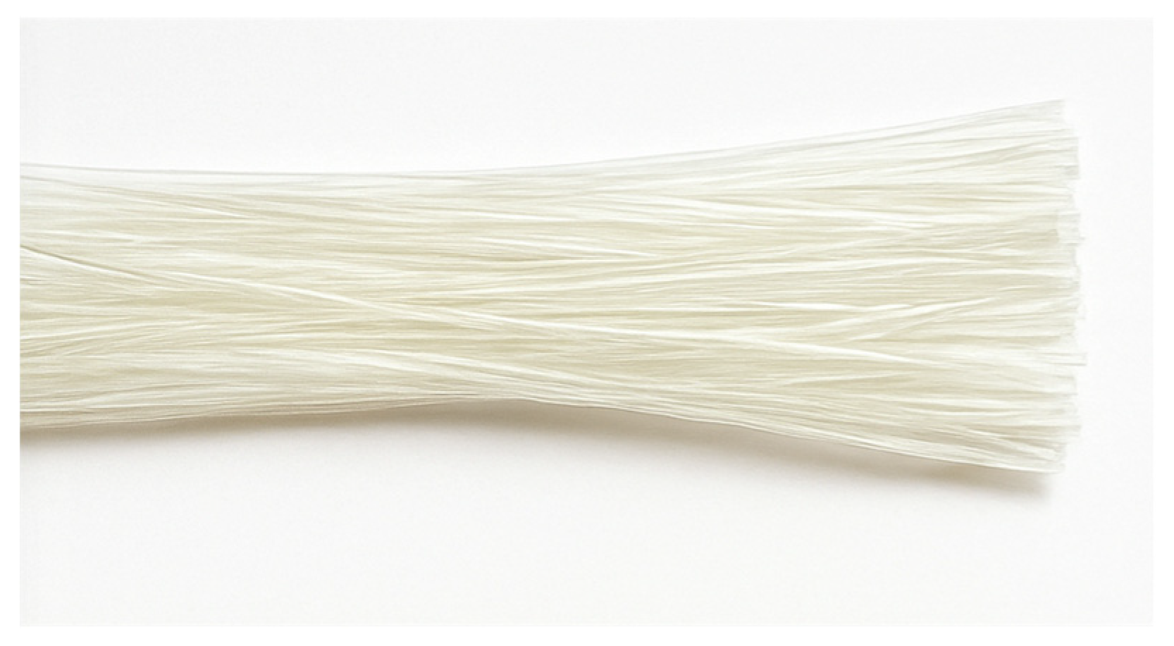
Glass fibers typically appear as smooth, translucent strands that can be woven, chopped, or bundled depending on the required composite configuration.
Figure 7 shows a representative image of glass fibers, highlighting their smooth, continuous, and translucent filament structure, which contributes to their high tensile efficiency and effective stress transfer within polymer matrices
6.2. Aramid Fibers
Aramid fibers represent a class of high-performance synthetic fibers characterized by excellent tensile strength, low density, and superior resistance to impact and abrasion. They are significantly lighter than steel while maintaining considerable mechanical strength, making them a practical and cost-effective alternative for reinforcement in fiber-reinforced polymer (FRP) composites. Although their tensile modulus is lower than that of carbon fibers, aramid fibers possess outstanding toughness and energy absorption capacity, which makes them particularly effective in applications requiring high impact resistance and fatigue durability. The modulus of elasticity of aramid fibers is approximately one-quarter that of prestressing steel, with a specific density nearly one-sixth of steel. These fibers are typically manufactured in the form of continuous strands, ropes, or woven fabrics and are commercially available under trade names such as Kevlar, Twaron, Technora, Arapree, FiBRA, and Parafil. Their tensile strength generally ranges between 2800 and 4210 MPa, with elastic moduli varying from 74 to 179 GPa, depending on the manufacturing process and fiber grade.
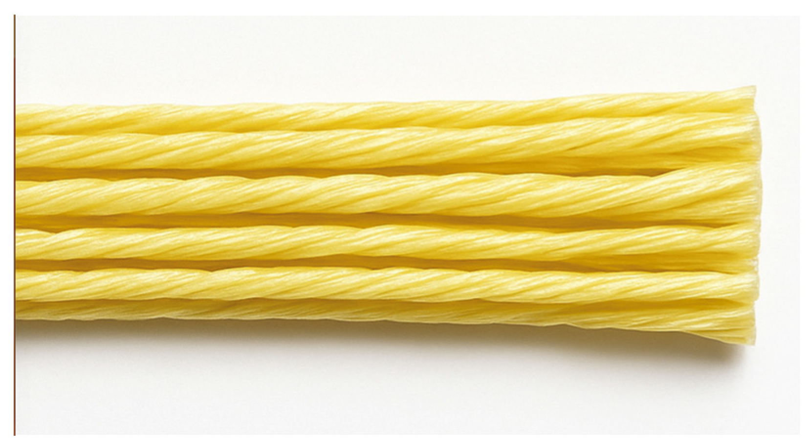
Aramid fibers are recognizable by their golden-yellow color and slightly rough, twisted texture, which enhances frictional performance and improves bonding with polymer matrices.
Figure 8 illustrates a bundle of aramid fibers, showing their characteristic yellow hue and textured surface, which contribute to their high strength-to-weight ratio and superior interfacial bonding with resin matrices.
6.3. Carbon Fibers
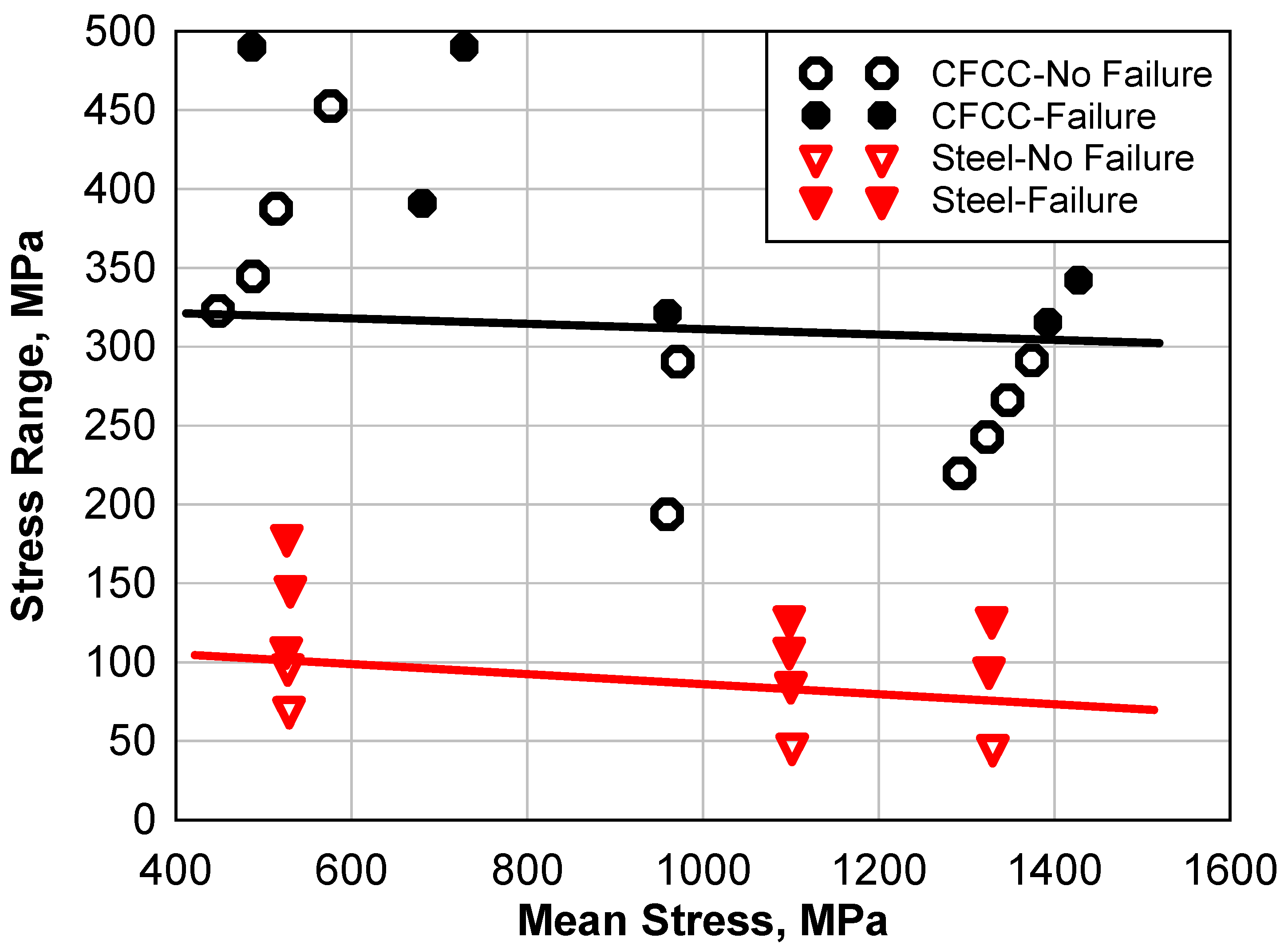
Carbon fibers possess exceptionally high tensile strength, stiffness, and fatigue resistance, making them ideal for prestressing and structural strengthening applications. Their high strength-to-weight ratio and very low coefficient of thermal expansion provide superior dimensional stability and efficiency under varying loads and temperatures. Moreover, carbon fibers can retain their strength at temperatures reaching up to 2000 °C, making them suitable for demanding environments. However, their drawbacks include relatively low impact resistance and high electrical conductivity, which necessitate proper insulation in certain applications.
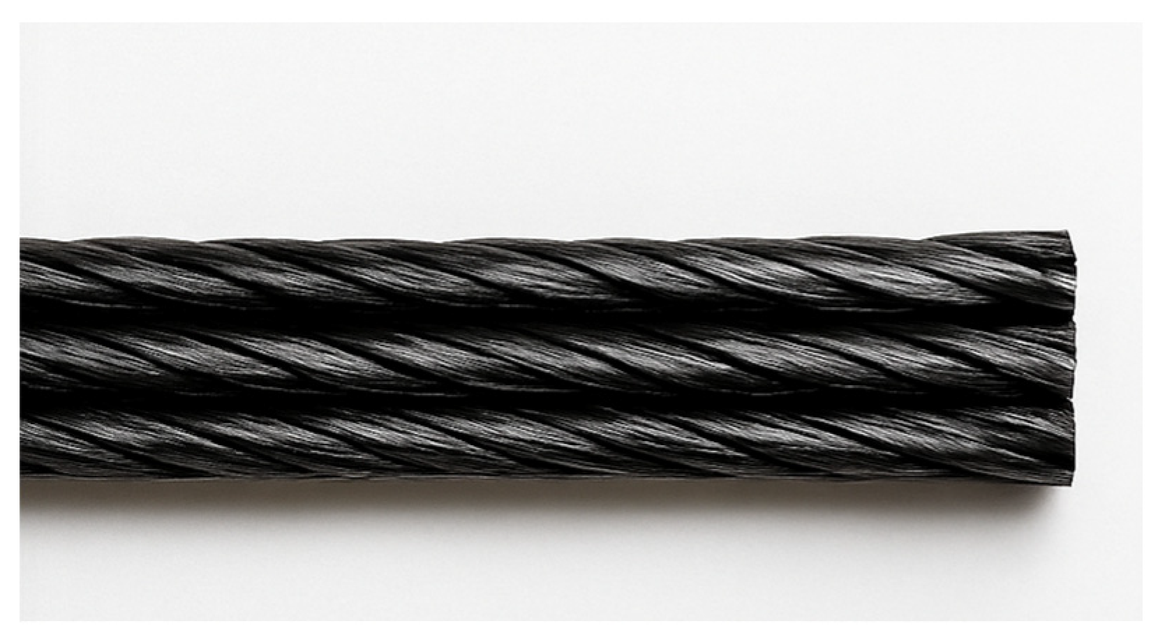
Figure 9 shows the characteristic appearance of carbon fibers as black, glossy woven strands.
Two main types of carbon fibers are commonly used: (1) synthetic fibers derived from polyacrylonitrile (PAN), similar to those used in textiles, and (2) pitch-based fibers obtained through the destructive distillation of coal [
73]. PAN-based CFRP is used to produce unidirectional carbon fiber composite cables (CFCC), developed by Tokyo Rope Manufacturing Co. Ltd. and Toho Rayon Manufacturing Co. Ltd., both in Tokyo, Japan. These cables can be manufactured as single rods or assembled into multi-strand cables comprising seven, nineteen, or thirty-seven rods.
Pitch-based CFRP was developed by Mitsubishi Kasei Chemical Company, Tokyo, Japan, for producing both round and deformed Leadline CFRP rods. The plain round bars range from 3 mm to 17 mm in diameter, while the deformed bars range from 5 mm to 12 mm.
8. Prior Studies and Applications
Extensive research has been carried out to evaluate the structural performance of CFRP-prestressed concrete elements in bridge applications. These investigations have focused on parameters such as prestressing techniques, tendon types, failure modes, serviceability, and anchorage systems. The following is a summary of key experimental and analytical studies that have contributed to understanding the behavior and feasibility of CFRP tendons in structural systems:
Grace and Abdel-Sayed [
82] developed an innovative bridge system utilizing precast, post-tensioned double-tee (DT) girders internally prestressed with CFRP strands and deck slabs reinforced with GFRP bars. The system incorporated externally draped CFRP tendons and epoxy-bonded shear connectors. Their findings highlighted significant improvements in durability, reduced corrosion potential, accelerated construction, and cost efficiency. The bridge exhibited minimal cracking and required low maintenance, demonstrating the effectiveness of combined internal and external CFRP reinforcement.
Grace et al. [
83] investigated the flexural performance of a full-scale DT beam prestressed with bonded CFRP tendons and unbonded CFCC post-tensioning strands. The beam configuration replicated those used in the Bridge Street Bridge, the first vehicular concrete bridge in the United States reinforced with CFRP. The experimental results showed high reserve capacity, with both ultimate and cracking loads substantially exceeding service loads. Failure initiated through partial separation of the topping and crushing of concrete, while the external CFCC strands and their anchors remained intact, emphasizing system resilience.
Grace et al. [
84] analyzed the flexural behavior of concrete box beams prestressed with CFRP tendons using varying combinations of pretensioning and post-tensioning. Beams with both pretensioned and unbonded post-tensioned CFRP strands exhibited superior ultimate load capacities. An optimal combination of 40% pretensioning and 70% post-tensioning maximized structural performance. Failure modes ranged from concrete crushing to tendon rupture, depending on the applied stress levels, underlining the importance of balanced prestressing strategies.
Noel and Soudki [
85] experimentally evaluated the impact of prestressed CFRP tendons on GFRP-reinforced concrete slab bridges. Their study revealed that GFRP slabs without prestressing performed comparably to steel-reinforced slabs in terms of ultimate load but showed inferior serviceability. The introduction of CFRP prestressing significantly improved service behavior by reducing deflections and limiting crack widths. Higher prestressing levels not only increased the load capacity but also altered failure modes, allowing greater deformation before failure.
Grace et al. [
86] examined the use of unbonded longitudinal post-tensioning with CFCC in concrete box-beam bridges to combat corrosion. Testing on three bridge models demonstrated that increasing the level of prestressing delayed the onset of cracking, reduced crack widths, and minimized residual deflections. However, it was also observed that in some cases, failure occurred due to concrete crushing before full utilization of the tendon capacity, indicating a potential inefficiency in tendon usage.
Xue and Tan [
87] conducted tests on six prestressed concrete beams using bonded CFRP tendons combined with either steel or GFRP reinforcements. The study explored the effects of prestressing ratio, tendon quantity, reinforcement material, and jacking stress on crack behavior. Results indicated that combining CFRP tendons with traditional reinforcements substantially reduced crack widths. Nonetheless, beams with FRP-only reinforcement exhibited wider cracks compared to those containing steel, under equivalent load conditions, suggesting the need for hybrid reinforcement in certain applications.
Schmidt et al. [
88] reported on a collaborative project aimed at developing a reliable mechanical anchorage system for FRP tendons. Their work involved shear stress testing, anchor geometry optimization, and finite element modeling. Despite these efforts, a fully effective mechanical anchorage solution for external CFRP post-tensioning has yet to be achieved. Challenges such as stress concentration, difficulty in simulating frictional behavior, and premature failures continue to limit commercial application. Further development and testing are essential for safe and economical implementation.
Grace et al. [
89] studied a half-scale precast, prestressed concrete box-beam bridge model with transverse post-tensioning using unbonded CFCC strands. The study showed that increasing the number of transverse diaphragms had negligible influence on load distribution and strain behavior prior to cracking. However, after cracking, diaphragm additions improved structural behavior. The model experienced ductile flexural failure without rupture of the CFRP tendons. Additionally, the use of oval ducts proved advantageous for accommodating strand alignment variations during construction.
9. Conclusions
This review has provided a comprehensive examination of strengthening techniques for steel–concrete composite beams, addressing their structural behavior, design evolution, and performance under various connection and loading conditions. The synthesis of past and current research confirms that the integration of steel and concrete enables a superior composite action that enhances load-bearing efficiency, stiffness, ductility, and long-term durability compared with conventional construction systems.
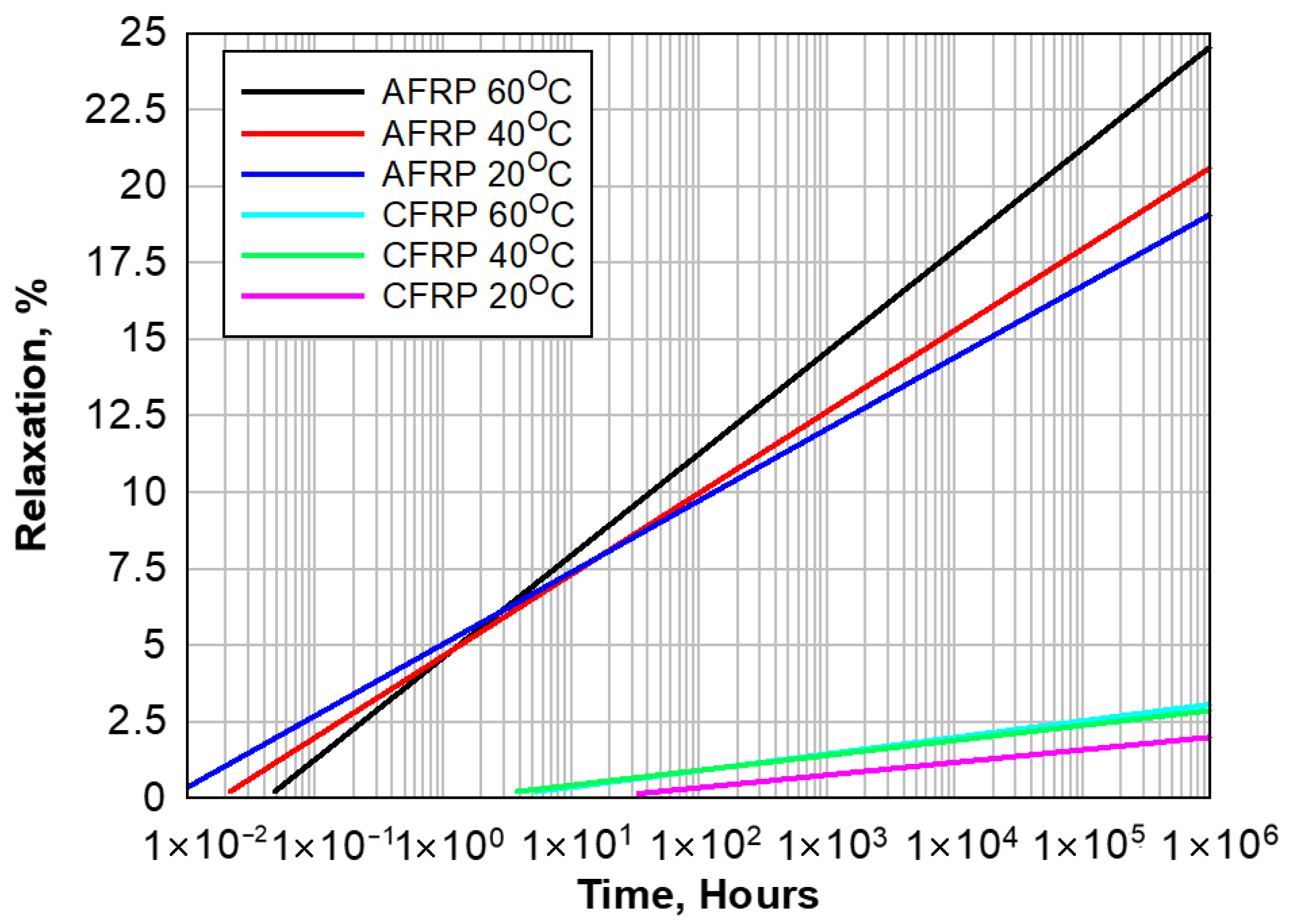
Among the explored strengthening strategies, external post-tensioning systems have shown exceptional potential for improving flexural capacity, delaying cracking, and enhancing stiffness, particularly in continuous and negative bending regions. Their ability to redistribute internal forces and improve serviceability renders them highly effective for both new construction and retrofitting of aging structures. Similarly, fiber-reinforced polymer (FRP) materials have emerged as viable alternatives to steel tendons, offering excellent corrosion resistance, low weight, and strong fatigue endurance. The long-term stability and minimal relaxation behavior of FRP tendons have demonstrated significant promise for sustainable and low-maintenance infrastructure solutions.
The review also emphasizes the critical influence of partial shear connection on the mechanical performance of composite beams. The type, arrangement, and degree of shear connectors significantly affect the stiffness, load-slip response, and ductility of composite members. Experimental and numerical investigations consistently indicate that partial interaction governs the overall flexural behavior and failure mode of the system. However, despite extensive progress, a unified design framework that integrates modern materials, nonlinear response, and long-term interaction effects remains lacking.
Current challenges in this field include the need for refined models that capture fatigue degradation, time-dependent effects such as creep and shrinkage, and the combined influence of temperature and cyclic loading. Additionally, while advanced finite element modeling has become increasingly powerful, discrepancies still exist between numerical predictions and experimental outcomes, particularly in large-scale applications and composite connections subjected to dynamic or fatigue loading.
In summary, steel–concrete composite beam technology continues to evolve toward more efficient, durable, and sustainable solutions. The combined use of innovative materials, refined analytical models, and advanced experimental methods provides a strong foundation for future breakthroughs. Continued interdisciplinary collaboration between researchers, practitioners, and code developers will be essential to translate these advancements into consistent, safe, and performance-based design practices for next-generation composite structures





 ,
,