Article

A Comprehensive Examination of Key Characteristics Influencing the Micro-Extrusion Process for Pure Copper Cross-Shaped Couplings

by
Thu Nguyen Thi
*,
Thuy Mai Thi
* and
Minh-Quan Nguyen
*
School of Mechanical Engineering, Hanoi University of Science and Technology, Hanoi 100000, Vietnam
*
Authors to whom correspondence should be addressed.
Eng 2025, 6(10), 250; https://doi.org/10.3390/eng6100250
Submission received: 6 August 2025 / Revised: 16 September 2025 / Accepted: 28 September 2025 / Published: 1 October 2025
(This article belongs to the Topic Surface Engineering and Micro Additive Manufacturing)

Abstract

In the manufacturing of micro-scale components, geometric dimensional accuracy and product quality are critical factors that directly influence both production costs and efficiency. To meet the growing demands in this field, micro-extrusion technology has been developed and extensively applied, particularly in mass and bulk production. This technology is considered an optimal solution for improving dimensional accuracy, enhancing mechanical properties, increasing production efficiency, and reducing costs compared to traditional methods, while also aligning with the current trends of modern industrial development. This study investigates the influence of temperature and friction on forming force, formability, and product quality during the micro-extrusion process. A combined approach of simulation and experimentation was utilized to form cross-shaped coupling components using pure copper as the material. The results indicate a significant relationship between temperature, friction coefficient, and forming force. Furthermore, 550 °C is identified as the most suitable temperature for hot forming, providing a balance between force reduction and product quality. These insights enhance the predictability and control of the micro-extrusion process and contribute to reducing production defects. Ultimately, the findings support wider implementation of micro-extrusion in the manufacturing of high-accuracy small-scale parts and align with modern trends emphasizing miniaturization, automation, and cost efficiency.

1. Introduction

In the past several years, micro-forming technology has made significant advancements, driven by the rapid development of advanced technologies and the increasing demands of various industries. The manufacturing process has been optimized through the integration of automation and intelligent control systems based on artificial intelligence (AI). These innovations not only enable the cost-effective and efficient mass production of micro to ultra-micro components but also substantially reduce production defects, meeting the growing demands of the market [1,2,3,4]. Micro-forming, based on the principle of metallic plastic deformation, is recognized as a promising technique with numerous superior advantages and has garnered significant attention from researchers [5,6,7,8,9]. This technology has found widespread applications across various sectors such as electronics, medical devices, biomedical engineering, micro-surgical instruments, aerospace, automotive, and energy [10]. Notably, in the context of modern industry shifting towards smart factories and sustainable production models, micro-forming technology has emerged as a strategic solution. Thanks to its outstanding advantages, such as material savings, high productivity, and reduced energy consumption, this technology not only avoids the generation of pollutant emissions but also aligns well with the trend of green manufacturing. Moreover, its flexible integration into automated production systems further enhances its practical applicability in the context of modern industry. This technology has the potential to play a pivotal role in shaping the future of industrial manufacturing [11,12].
Micro-forming is a metal-forming process conducted at the micro-scale, where the characteristic size of the product or forming area is smaller than 1 mm (or at least one dimension is ≤1 mm for bulk-shaped components) [13].
However, this technology also faces numerous significant challenges, with one of the prominent issues in micro-extrusion technology being the grain size effect. The influence of grain size on the micro-forming process contributes to variations in punch stroke and the emergence of forming defects such as micro-cracks, pits, surface irregularities, and longitudinal surface textures, which are predominantly observed in the body and tail regions. Additionally, coarse-grained materials are more prone to the formation of micro-voids [14]. The influence of the grain size effect on the curvature during micro-extrusion has also been highlighted, with methods proposed to eliminate this effect by extending the length of the bearing to the exit diameter length [7]. Symmetrical reverse extrusion experiments with different initial grain sizes have yielded mechanical responses and deformation behaviors for Cu110 and Al1100 alloy rod specimens [15]. Micro-forming technology entails significantly greater requirements in terms of precision, processing speed, and large-scale production, which conventional forming machines are typically unable to fulfill [16]. Consequently, production systems and machine development have become an area of significant interest in recent research. The process of micro-extrusion of miniature heat pipes with axial micro grooves presents particular difficulties due to the extreme extrusion ratios and complex cross-sectional shapes, which have been successfully addressed [17]. Several research works on micro-forming also explore the topic of materials, with copper being the most widely studied, followed by aluminum, magnesium steels, and their alloys [18,19,20]. Recently, new or difficult-to-deform materials such as silicon, composites, stainless steel, magnesium alloys, and titanium have become a fascinating topic of interest among researchers [21,22,23]. Studies have focused on controlling the effects of the size effect and formability in micro-forming technology, proposing suitable methods and equipment for forming various materials using micro-forming techniques. Among the influencing factors, friction and temperature are two prominent research topics, attracting widespread attention globally with many scientific publications [24,25,26,27]. To improve the formability of the process, numerous researchers have proposed and developed various High Energy Metal Forming (HERF) techniques, including ultrasonic vibration, explosive forming, magnetic forming, electro-hydraulic forming, and thermal processes, aimed at enhancing both the formability and precision of products with micro-scale dimensions [28,29,30,31,32]. A novel model features a specialized porous sonotrode platform and press machine, which allows for flexible control of different ultrasonic vibration modes, either tool vibration or billet vibration, to enhance micro-forming capabilities [33]. Most current research on micro-extrusion technology primarily focuses on forming components with simple shapes, composed of cylindrical cups, H-shaped cylindrical cups, and more complex parts like connectors or gears. Meanwhile, in-depth research on forming processes for more complex components, such as cross-shaped couplings, is still relatively limited. Couplings, with their function of transmitting torque between rotating parts continuously and efficiently, play a crucial role in minimizing slippage and vibration—factors that can cause significant deviations in the manufacturing of micro-scale products [34]. In addition to their role in mechanical drive, couplings also compensate for misalignments due to assembly errors or thermal deformation, thereby maintaining concentricity and improving the overall durability of the mechanical system [35]. Notably, couplings designed with elastic structures or integrated damping mechanisms effectively dampen dynamic vibrations, helping stabilize material flow within the mold and improving the geometric precision of the product. Furthermore, couplings contribute to optimizing assembly processes, maintenance, and system reconfiguration, thus enhancing flexibility in equipment operation [23]. However, existing studies have yet to fully address the effects of factors consisting of friction and temperature on the product-forming process and assess product quality in micro-extrusion technology.
Utilizing numerical simulation, this study investigates the interplay between friction, temperature, and forming force in the micro-extrusion process. The simulation results were validated through corresponding experimental trials. The findings reveal that both friction and temperature exert a significant influence on the forming force and the overall quality of the micro-formed components. Notably, the precise identification of optimal friction coefficients and forming temperature ranges is shown to improve dimensional accuracy and product quality. These results offer valuable insights into enhancing micro-forming performance and demonstrate strong practical relevance for the fabrication of complex and high-precision components, such as cross-shaped couplings, which are increasingly demanded in advanced manufacturing industries. To visually illustrate the objectives and overall implementation process of the study, Figure 1 presents a summary diagram that clearly outlines the research direction and the main steps undertaken in this work.

2. Materials and Methods

2.1. Objective

The subject of this study is a cross-shaped coupling component fabricated from commercially pure copper. In the field of micro-extrusion technology, such coupling elements play a pivotal role in ensuring high precision and stability during the forming process. Due to their superior technical characteristics, cross-shaped couplings are widely implemented in micro-extrusion systems designed to produce ultra-small components with stringent technical requirements. Typical applications include biomedical devices such as catheter tubes, microelectronic circuits, and microelectromechanical systems (MEMS) [36].
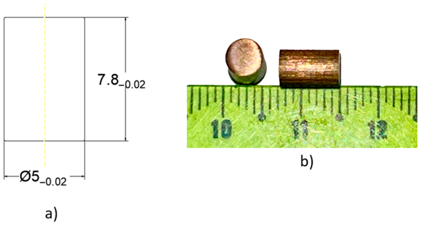
Commercially pure copper was selected as the workpiece material for the micro-extrusion experiments due to its favorable mechanical and thermal properties. Copper wires with a diameter of 5 mm were cut into cylindrical billets. The billets were then polished to achieve a final diameter of 5 mm and a height of 7.8 mm, as illustrated in Figure 2. This ensured surface consistency and dimensional uniformity prior to forming.
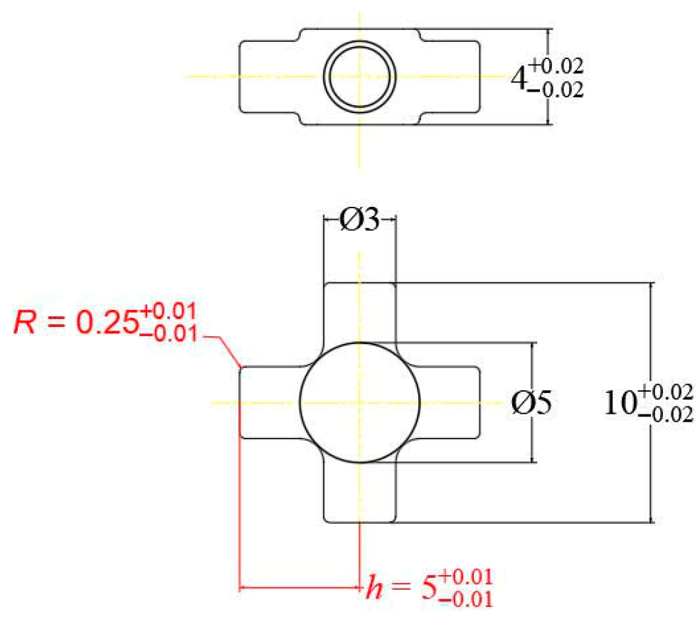
The quality of the extruded products was evaluated based on two primary geometric parameters: the branch height (h) and the apex radius (R), as depicted in Figure 3. The formed components were considered dimensionally acceptable when the branch height reached h = 5 mm and the apex radius measured R = 0.25 mm. These values represented the target specifications for accurate and functional cross-shaped coupling components.
The central goal of this research is to elucidate the critical relationship between forming force, friction, and temperature, as these variables contribute significantly to the determination of both the efficiency and quality of the micro-forming process. Through comprehensive numerical simulations and experimental investigations, the study aims to systematically evaluate the individual and combined effects of friction and temperature on the forming process. The findings will help identify the optimal conditions for friction coefficients and temperature ranges, thereby enhancing the formability and ensuring the dimensional accuracy of components with complex geometries. Additionally, the research seeks to provide a solid scientific foundation for selecting appropriate equipment and processing parameters, improving experimental consistency and enabling better industrial applications. Ultimately, this study aims to advance the field of micro-extrusion technology, contributing to its capability to fabricate precision components and expanding its application in the context of modern industrial manufacturing.

2.2. Material

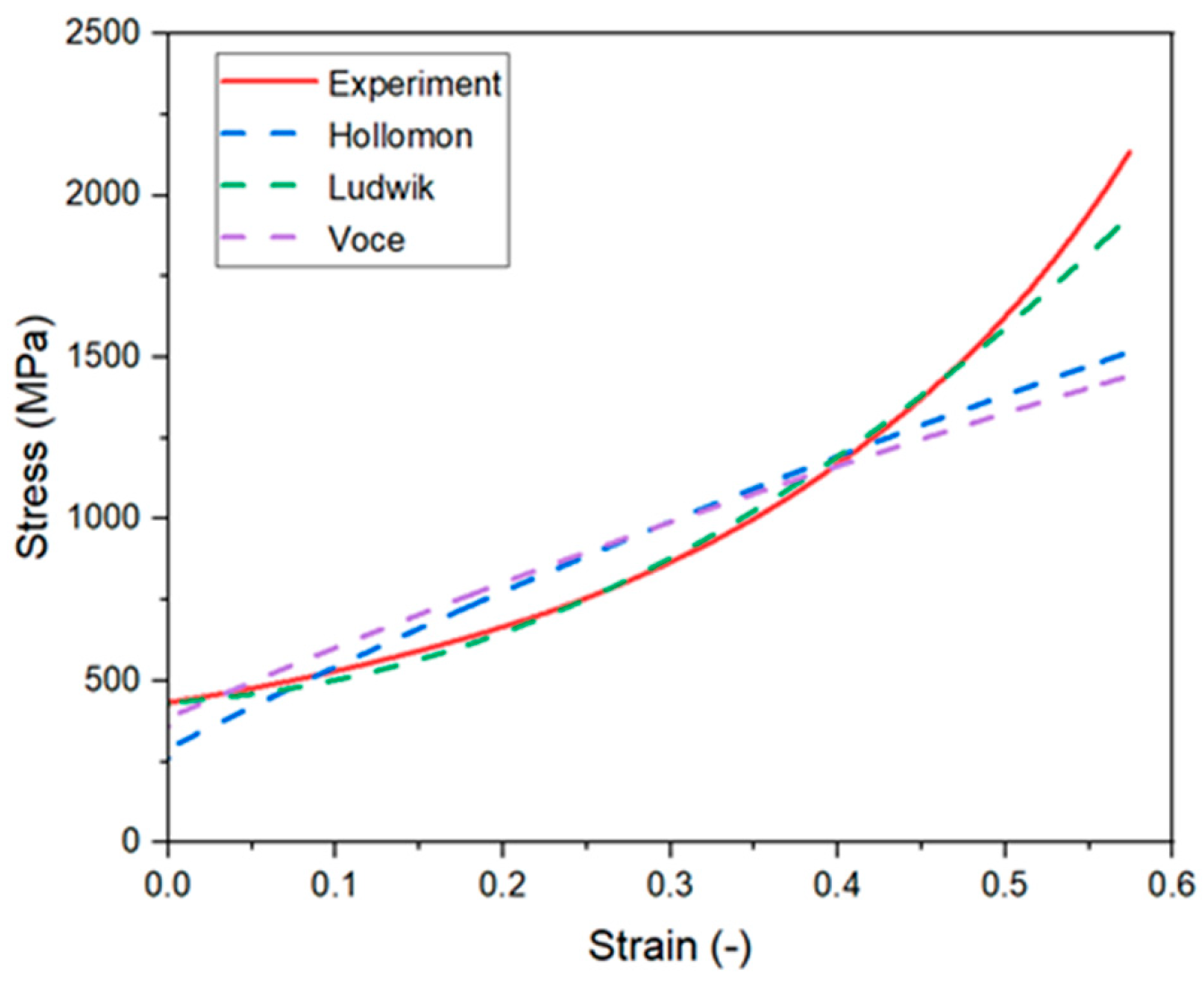
In this investigation, pure copper (Cu) was identified as the preferred material for the billets, with its basic chemical composition presented in Table 1. Pure copper is an optimal choice for micro-extrusion components due to its excellent properties. It possesses high electrical and thermal conductivity, second only to silver, which enhances performance in electronic and microelectromechanical systems (MEMS) applications while also improving heat transfer efficiency [37]. Additionally, pure copper has high ductility, which facilitates easy processing and shaping, reducing the risk of cracking during manufacturing. Furthermore, pure copper offers natural corrosion resistance through a protective oxide layer, enhancing its durability in humid environments or when exposed to mild chemicals. Beyond its mechanical strength, pure copper also demonstrates natural antimicrobial properties, making it particularly suitable for medical and bioelectronic applications. These exceptional characteristics make pure copper widely used in the production of electronic components, MEMS, medical devices, and precision micro-mechanics, thereby underscoring its vital role in micro-extrusion technology. In compression testing, widely used strain hardening models for pure copper include the Hollomon, Ludwik, and Voce laws. These constitutive models play a crucial role in capturing the material behavior during plastic deformation. The corresponding equations are presented as follows:
Hollomon :   σ = K · ε n ,
Ludwik :   σ = σ 0 + K · ε n ,
Voce :   σ = σ s ( σ s σ 0 ) · e x p ( b ε ) ,
where σ denotes the true stress (MPa), σ 0 is the yield strength (MPa), σ s is the saturation stress (MPa), K is the strength coefficient (MPa), ε corresponds to the true strain, and n is the strain-hardening exponent.
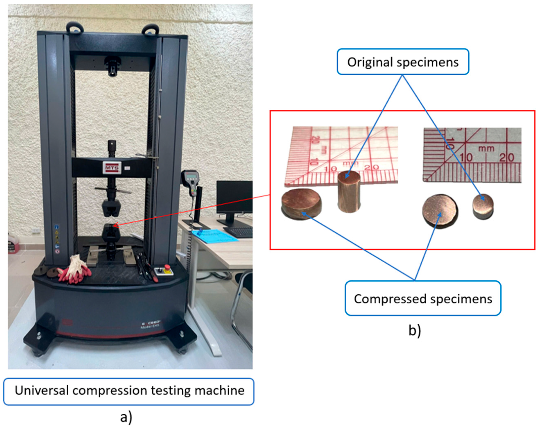
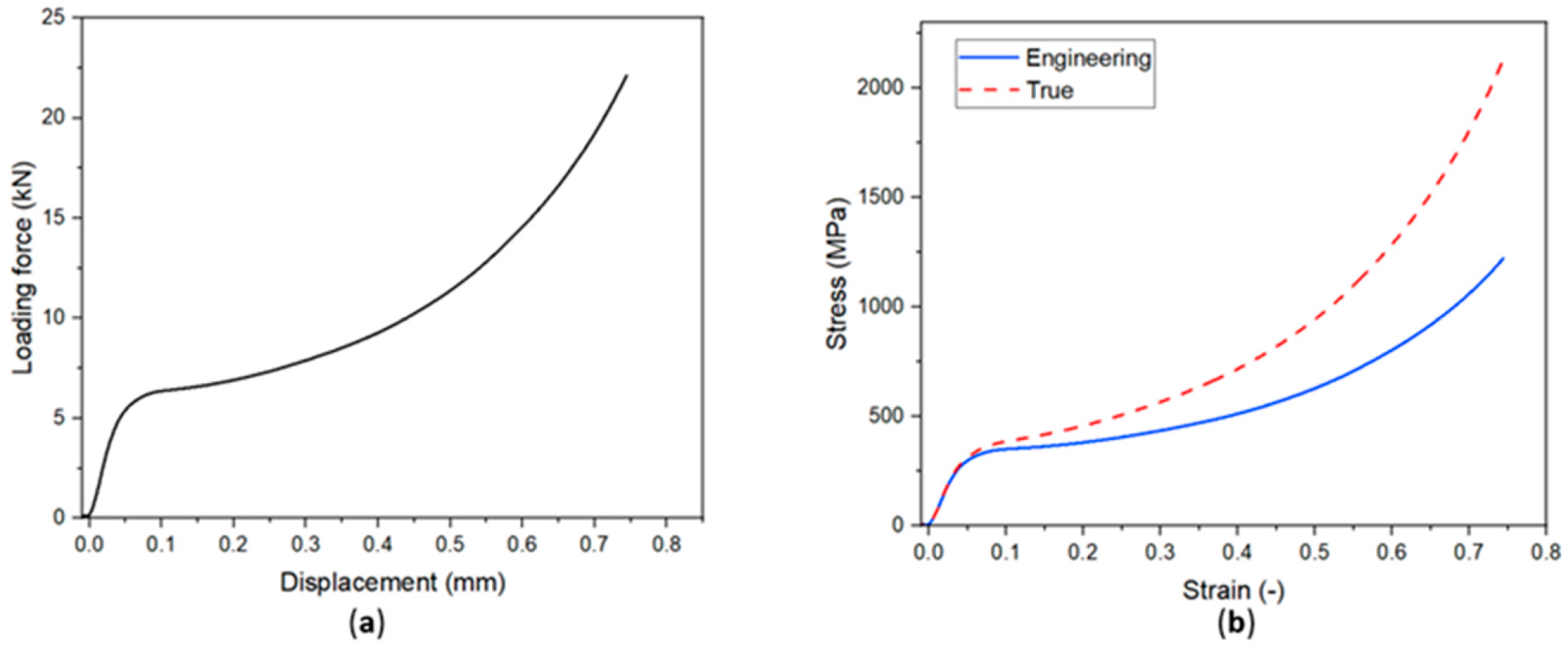
Compression tests on copper specimens were performed using a universal testing machine, as shown in Figure 4. The resulting stress–strain curves, presented in Figure 5, provided vital material parameters, encompassing loading force, displacement, and yield strength. Table 2 and Figure 6 present the parameters of the Hollomon, Ludwik, and Voce strain-hardening models, which were determined using the curve-fitting tool available in Microsoft Excel. This method minimizes the deviation between experimental data and theoretical models. Among the three models, the Ludwik model exhibited the smallest error and showed the best agreement with the experimental stress–strain curve. Therefore, the Ludwik law was selected as the constitutive model for the numerical simulations. The corresponding parameters, summarized in Table 2 and Table 3, were used as material input data in the ABAQUS finite element software (Abaqus 2017).

2.3. Methods

In this study, a combined numerical and experimental methodology was implemented to investigate and validate the micro-extrusion process. The ABAQUS finite element software was used to conduct numerical simulations, focusing specifically on the deformation characteristics of a cross-shaped coupling. Although micro-extrusion shares fundamental characteristics with conventional extrusion, it imposes stricter requirements regarding dimensional accuracy and the ability to form micro-scale features. A comprehensive model based on finite element analysis was established, comprising the essential components of the process—the punch, die, and billet—as depicted in Figure 7.
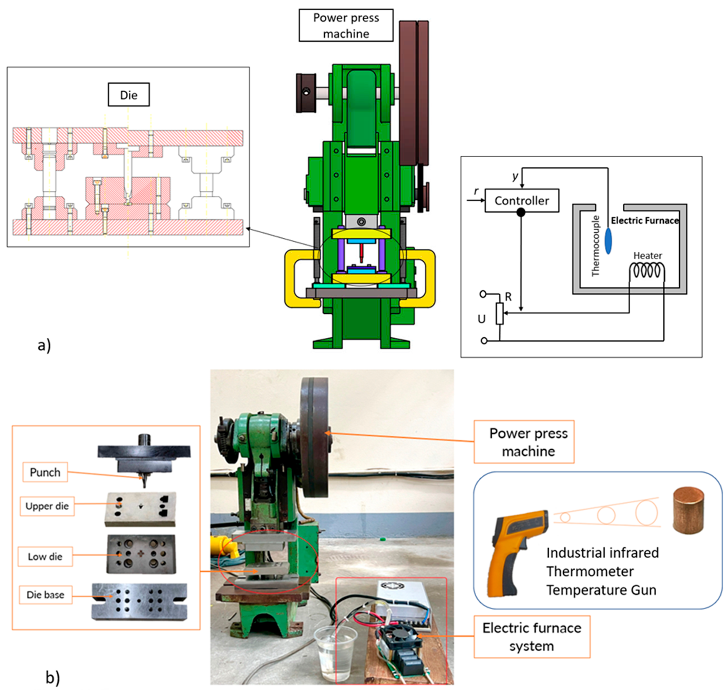
To validate the simulation results and assess the practical feasibility of the forming process, experimental trials were performed using a power press machine in combination with a simplified heating furnace, as illustrated in Figure 8. The die set was fabricated from SKD11 tool steel to ensure sufficient mechanical strength and thermal resistance during the forming operation. The procedure began with the placement of pure copper billets into the furnace, where they were heated to the target forming temperature. Temperature monitoring was conducted using an industrial infrared thermometer temperature gun to ensure precision and repeatability. Once the billet reached the desired temperature, it was quickly transferred into the die cavity. The punch then descended to initiate the micro-extrusion process, deforming the billet into the required geometry.
The surveys were conducted under clearly defined boundary conditions. Specifically, in the study evaluating the effect of the friction coefficient, the billet temperature was set at 350 °C, 550 °C, and 550 °C separately. Conversely, when investigating the impact of temperature, the friction coefficient was fixed at a value of 0.2. It is important to note that micro-extrusion technology has distinct characteristics compared to conventional forming technologies, leading to some modifications in the forming force equation. This force was determined according to Equation (4) below:
F = 1 η F k f m φ v A 1 ,
where F is the forming force, η F is the efficiency factor, k f m is the flow stress, φ v is the micro-size adjustment factor, and A 1 is the final cross-sectional area [38].

3. Results and Discussion

3.1. Numerical Simulation

3.1.1. Effects of Friction on the Forming Process and Product Quality

Friction exerts a crucial influence on the micro-forming process, with tribological characteristics significantly influencing grain size, grain boundary, and grain orientation [7]. One study highlighted that the friction coefficient not only affects tool wear rate but also impacts energy consumption levels when different coatings are applied to tool surfaces [39]. For a more detailed analysis, a model was constructed to evaluate the reduction in frictional stress under the influence of various ultrasonic vibration modes and analyze their influence on the reduction in forming stress [40]. Moreover, friction and wear-induced damage severely affect the performance and lifespan of forming components in micro-forming processes.
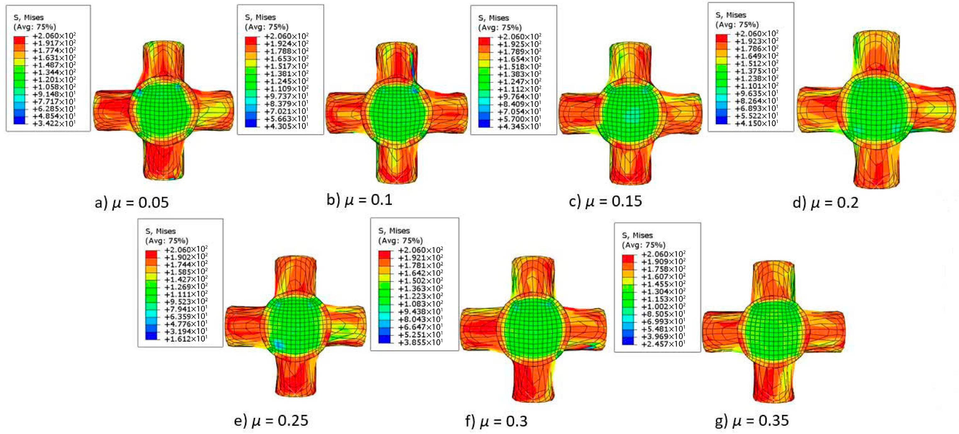
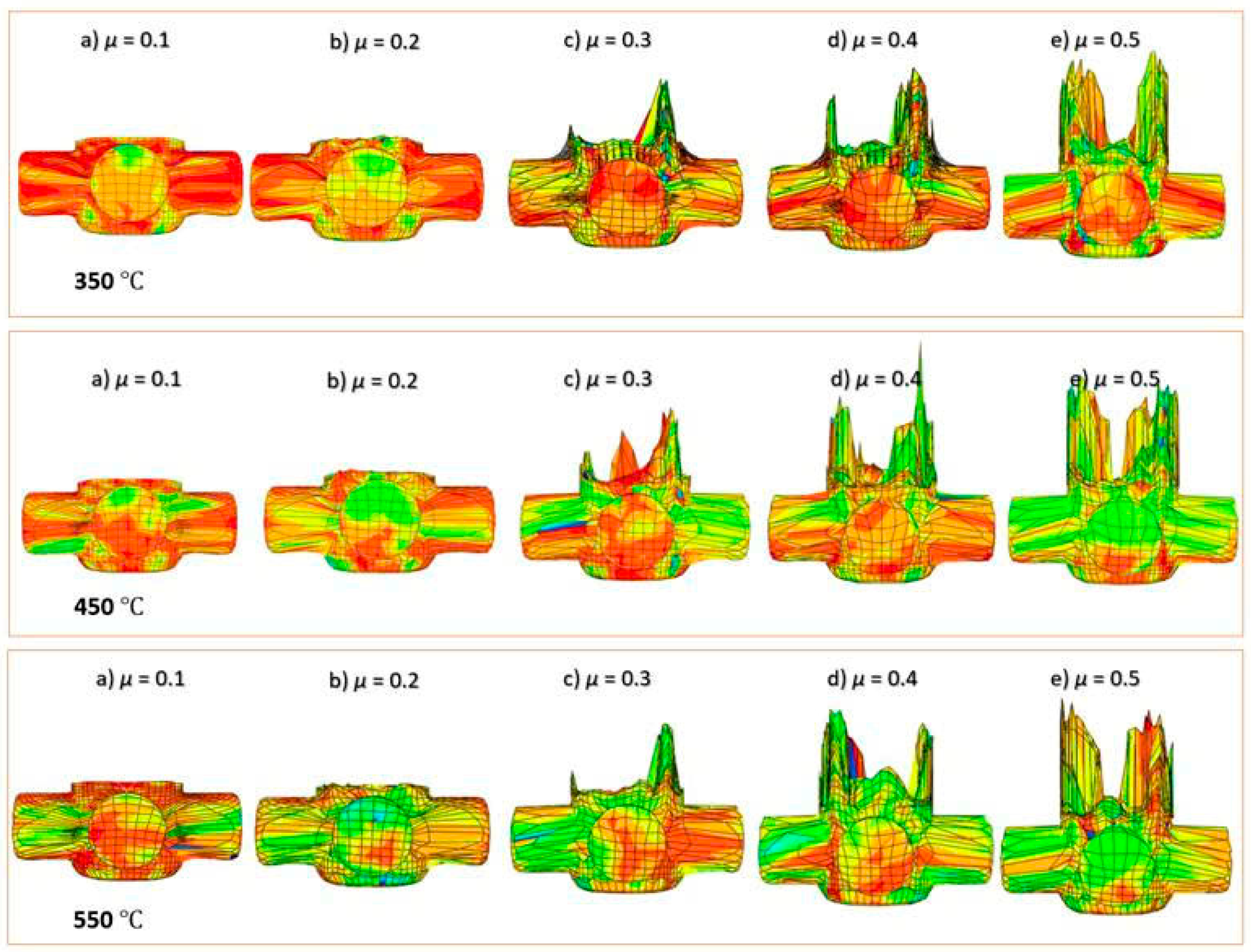
Friction between the billet and die surface impacts the forming force and additionally determines the uniformity of the deformation and the surface quality of the final product. The focus of this study is the impact of the friction coefficient on the micro-forming process of a cross-shaped joint component that was investigated. The simulation was set with boundary conditions corresponding to initial billet temperatures of 350 °C, 450 °C, and 550 °C, while the friction coefficient varied between 0.05 and 0.5, as illustrated in Figure 9 and Figure 10.
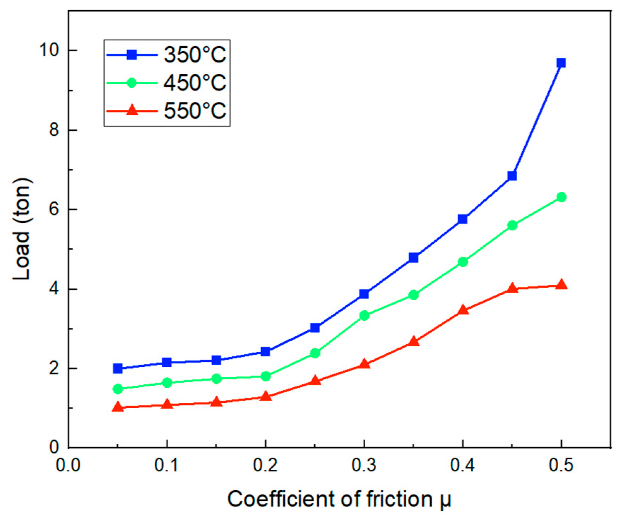
Through a series of simulations, the forming force data for the cross-shaped joint component were obtained for various cases. Specifically, when the billet temperature was 350 °C with friction coefficients of 0.05 and 0.5, the forming forces were 2 tons and 9.69 tons, respectively. When the billet temperature was 450 °C, with friction coefficients of 0.05 and 0.5, the forming forces were 1.49 tons and 6.32 tons, respectively. At a workpiece temperature of 550 °C, when the friction increased from 0.05 to 0.5, the forming force increased from 1.02 tons to 4.1 tons. Based on these results, a relationship between the friction coefficient and forming force was established for cases with varying billet temperatures (as shown in Figure 11). Upon examining the graph, it is evident that as the friction coefficient increases, the forming force required to produce the product increases significantly. Specifically, increasing the friction coefficient from 0.05 to 0.5 at billet temperatures of 350 °C, 450 °C, and 550 °C results in increases of 384.5%, 324.16%, and 301.96% in forming force, respectively. The quality of the products meets the required dimensions of h = 5 mm and R = 0.25 mm when the friction coefficient ranges from 0.05 to 0.25. Friction acts as a resistive force between the metal and the die surface. A lower friction coefficient results in lower frictional forces, reducing surface resistance during deformation. This facilitates easier metal flow into the die regions, particularly at the micro-scale, where surface effects are significant. As a result, the forming force decreases.
Furthermore, the simulation results indicated that at the friction coefficient µ of >0.3, the metal tends to flow backward into the gap between the punch and die before completely filling the outermost corner of the die. Clearly, the region at the top radius of the component is the most challenging area for metal filling, as the pressure in this zone is extremely high, obstructing the metal from completely filling this area. Additionally, under dry conditions, for copper materials, an optimal friction coefficient of µ = 0.2 is suitable for micro-extrusion processes. In macro-forming technologies, as the component size increases, the friction coefficient tends to rise. Conversely, in micro-forming, as the component size decreases, the friction coefficient increases. Future studies will investigate the influence of the friction coefficient on the size effect.

3.1.2. Effects of Temperature on the Forming Process and Product Quality

The microplastic deformation behavior of metallic components is enhanced as the forming temperature increases. Furthermore, the influence of the size effect on micro components has been significantly reduced [20]. An experiment with Al6063 across three different temperature ranges—room temperature, 100 °C, and 200 °C—demonstrated the effect of temperature on micro parts, demonstrating a decrease in the micro hardness of the extruded product in comparison to the billet’s micro hardness at room temperature [41]. The material selected for this investigation is copper, which has a melting temperature of 1083 °C, and its recrystallization temperature falls within the range of approximately 379.05 °C to 433.2 °C [42]. In the present study, the temperature range investigated spans from 350 °C to 750 °C, which corresponds to the semi-hot and hot working temperature range of copper. In the semi-hot working state, the crystal structure of the material is subjected to the combined effects of plastic deformation and relatively high temperature, leading to characteristic changes. At this temperature range, mechanisms such as dislocation, dynamic recovery, and, in some cases, dynamic recrystallization begin to occur. The dynamic recovery process helps to reduce dislocation density through the rearrangement of the crystal structure, contributing to the softening of the material without fully eliminating the deformed structure. If the deformation is sufficiently large and the temperature is high enough within the semi-hot range, new grain nucleation can occur at stress-concentrated regions, marking the onset of dynamic recrystallization. However, due to the temperature not being high enough to complete the development of new grains, the post deformation crystal structure typically exhibits a mixed structure, comprising regions that have undergone recovery and regions that still retain work-hardening characteristics [43,44]. The transformations involved play a fundamental role in optimizing the final mechanical properties and securing stability throughout the micro-forming process.
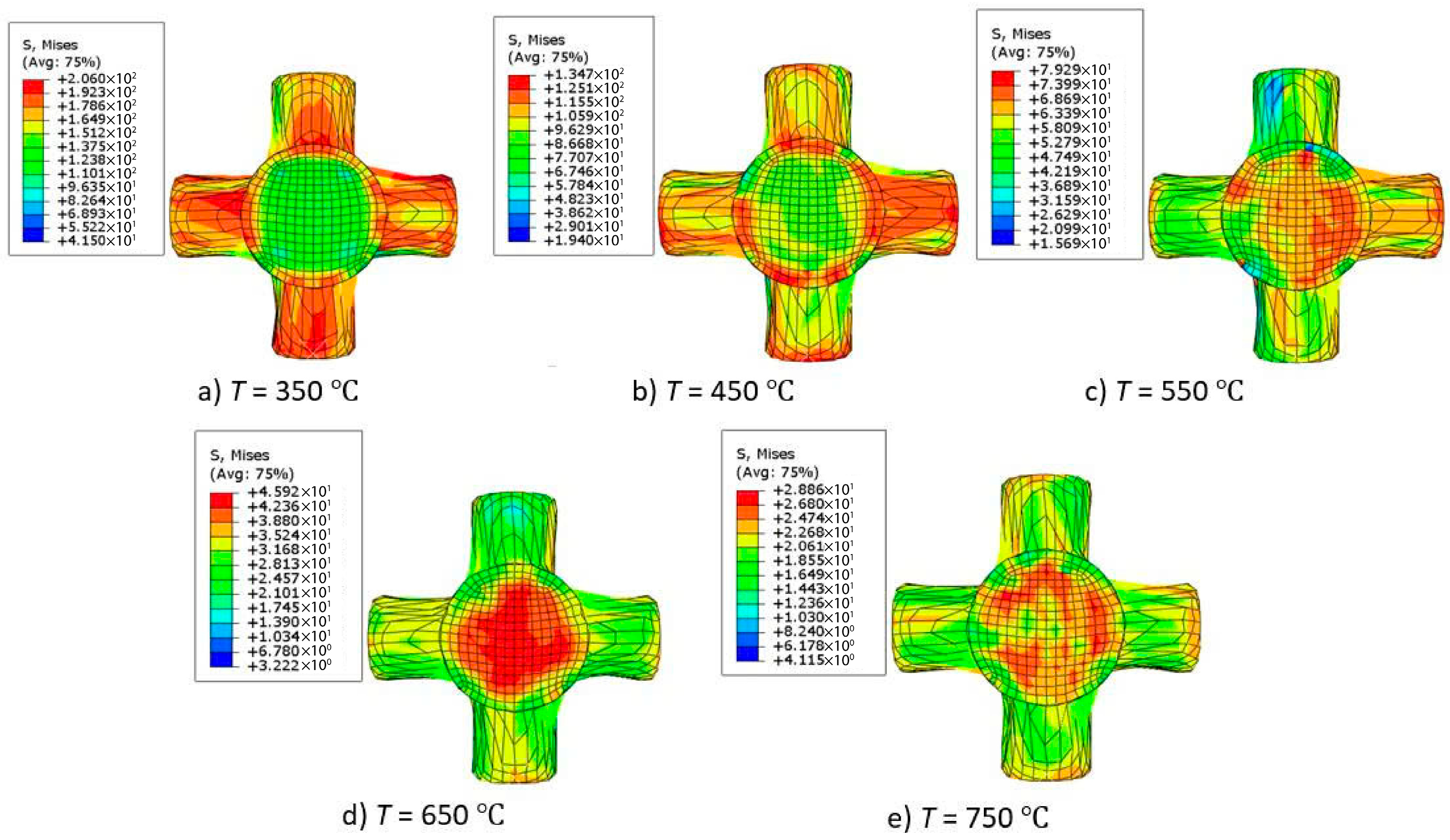
In micro-extrusion, temperature plays a significant role in the deformation capability of different materials. Additionally, the effect of interfacial heat transfer between the billet and die components, as well as between the billet−die and the surrounding environment, is key issues of considerable interest. While this study investigates the role of temperature in affecting the forming force, it does not incorporate heat transfer phenomena into the analysis. To evaluate the role of temperature in determining the forming force involved in micro-extrusion operations, the friction coefficient was fixed at μ = 0.2. A temperature range of 350 °C to 750 °C was employed, with variations introduced at 100 °C intervals. Figure 12 shows the simulation of the cross-shaped joint component in ABAQUS, illustrating the effect of billet temperature variation.
The statistical results illustrating the relationship between temperature and forming force, as shown in Figure 13 from the ABAQUS simulation software, indicate a clear trend where the forming force decreases significantly with increasing temperature. In the case of a billet temperature of 350 °C, the forming force is 2.43 tons, while at a billet temperature of 750 °C, the forming force drops to 0.52 tons. The quality of the products meets the dimensional requirements of h = 5 mm and R = 0.25 mm in all the cases investigated. It can be observed that as the billet temperature increases from 350 °C to 750 °C, the forming force decreases by 78.6%. This outcome results from the material’s flow stress diminishing progressively with rising temperature, due to enhanced thermal vibrations within the crystal lattice, which in turn reduces the force required to sustain the plastic deformation process. Additionally, mechanisms such as dynamic recovery become more effective, helping to decrease dislocation density and soften the material. Moreover, at higher temperatures, the ductility of the metal improves significantly, contributing to a reduction in material flow resistance within the die, which is especially crucial at the micro-scale where friction and size effects typically dominate. The reduction in contact friction between the billet and die at high temperatures also contributes to the overall decrease in forming force.

3.2. Experimental Result of Cross-Shaped Coupling

To determine the viability of the proposed method, experimental investigations were conducted within a thermal range approximating the recrystallization temperature on the cross-shaped joint component. In this study, billet temperatures of 350 °C, 450 °C, and 550 °C were selected, since the recrystallization temperature of copper is estimated to range approximately from 379.05 °C to 433.2 °C. The reason for conducting experiments within this temperature range is that when the metallic material is heated to the vicinity of the recrystallization temperature, significant microstructural changes occur in the crystal lattice. Initially, at temperatures below the recrystallization threshold, recovery processes take place, during which dislocations are rearranged and form subgrains, helping to reduce internal stresses in the material without significantly altering the grain size. When the temperature reaches or exceeds the recrystallization threshold, new, undeformed grains begin to form at sites with high dislocation density, such as grain boundaries or stress-concentrated regions. This process is known as recrystallization, and it completely alters the microstructure by replacing deformed grains with new, more stable grains. If heating continues after recrystallization, these new grains undergo grain growth, in which some grains increase in size while others are eliminated. Overall, these transformations have a significant impact on the material’s mechanical properties, reducing hardness and increasing ductility, thereby improving formability [43,44].
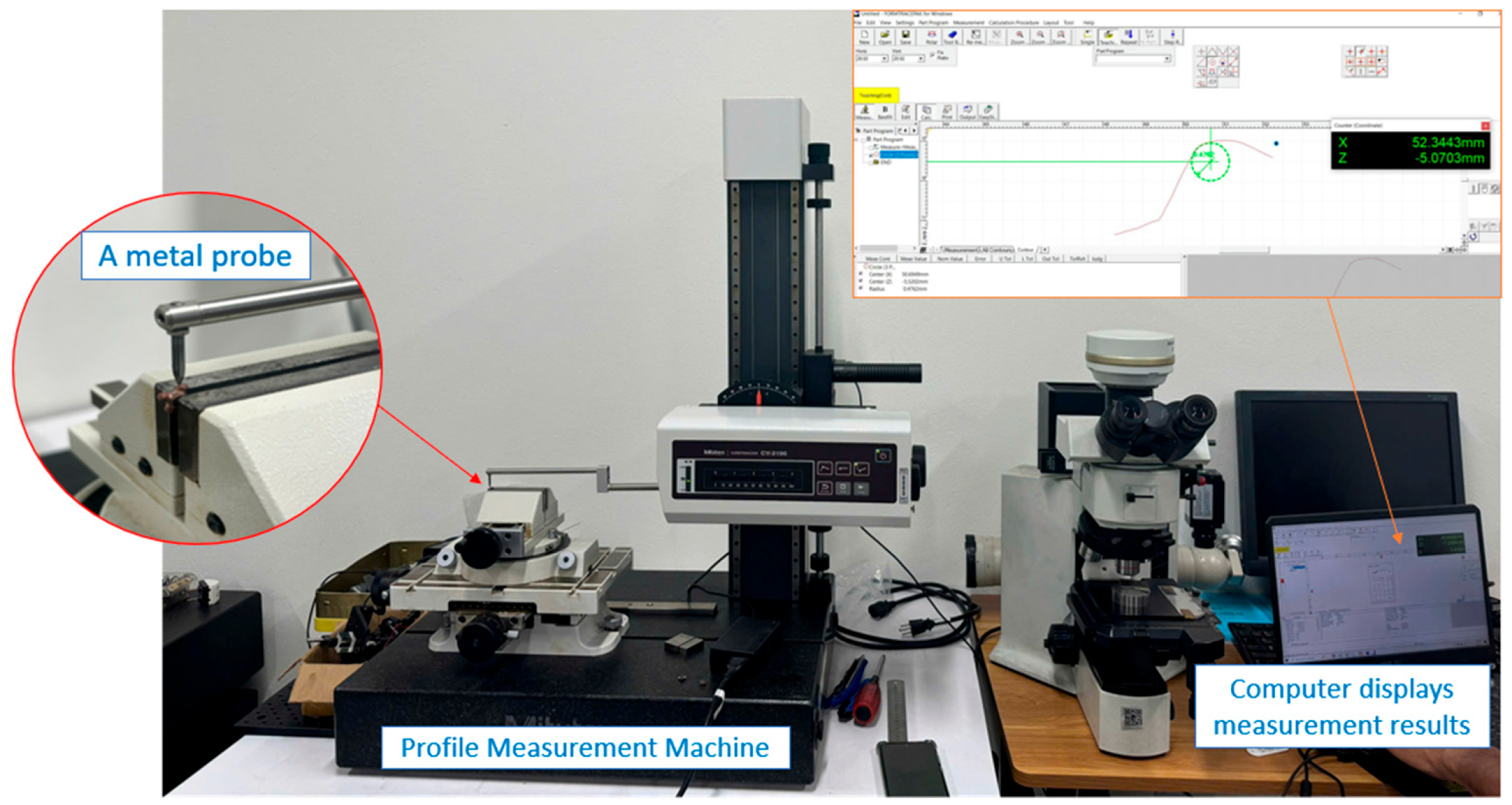
The measurement method used in this study involved a profile measurement machine, in which a metal probe moved along the surface contour of the specimen, as illustrated in Figure 14. The device was connected to a computer, which displayed the product profile on screen, allowing for the identification of point coordinates and the extraction of the required dimensions. Based on this, key geometric parameters such as branch height and the curvature radius at the apex were determined. Finally, the actual profile of the product was compared with the initial design profile to assess the degree of deviation and the accuracy of the product.
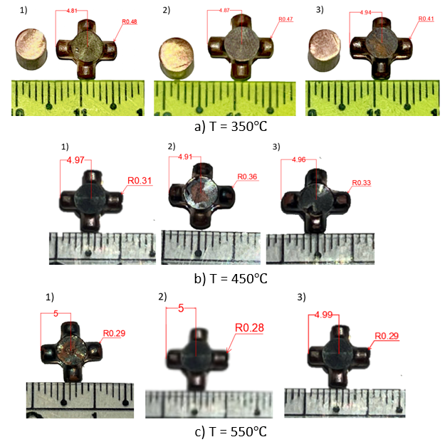
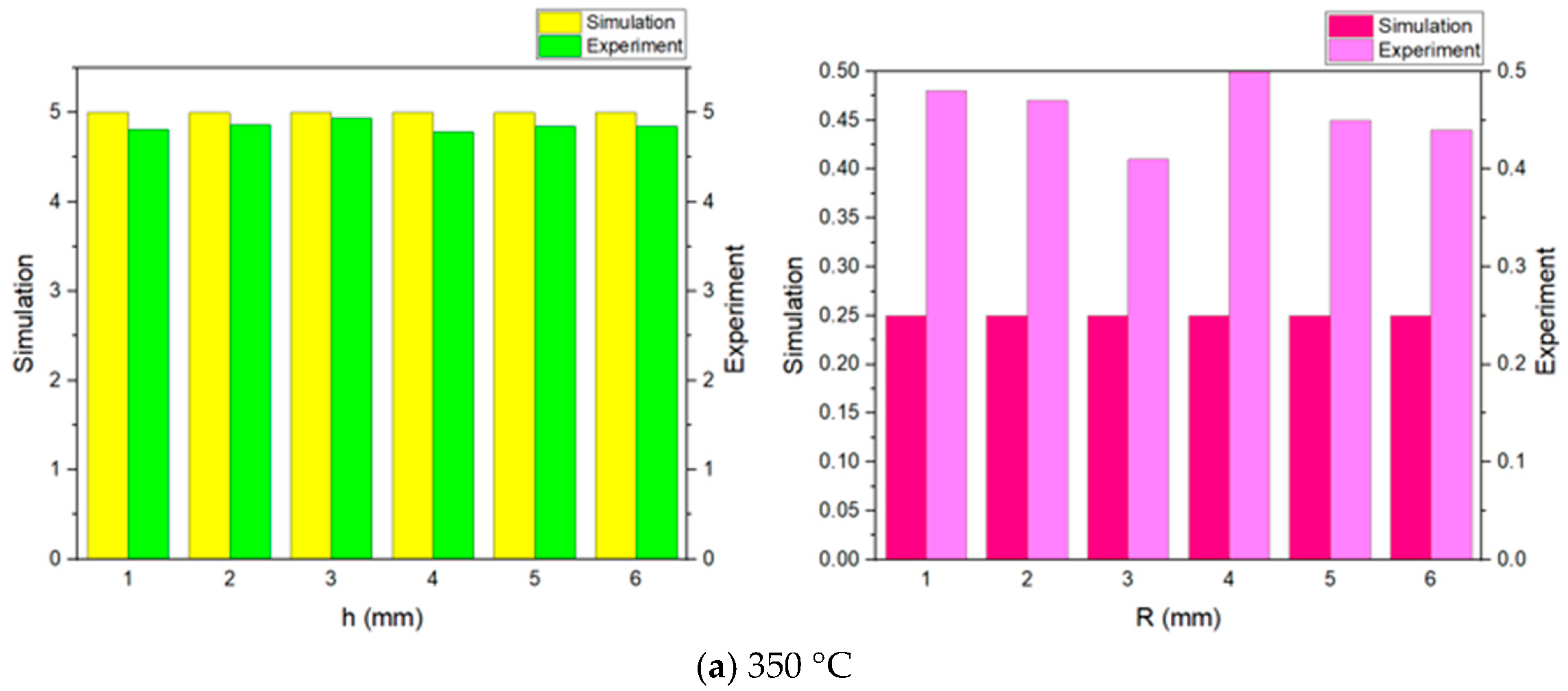
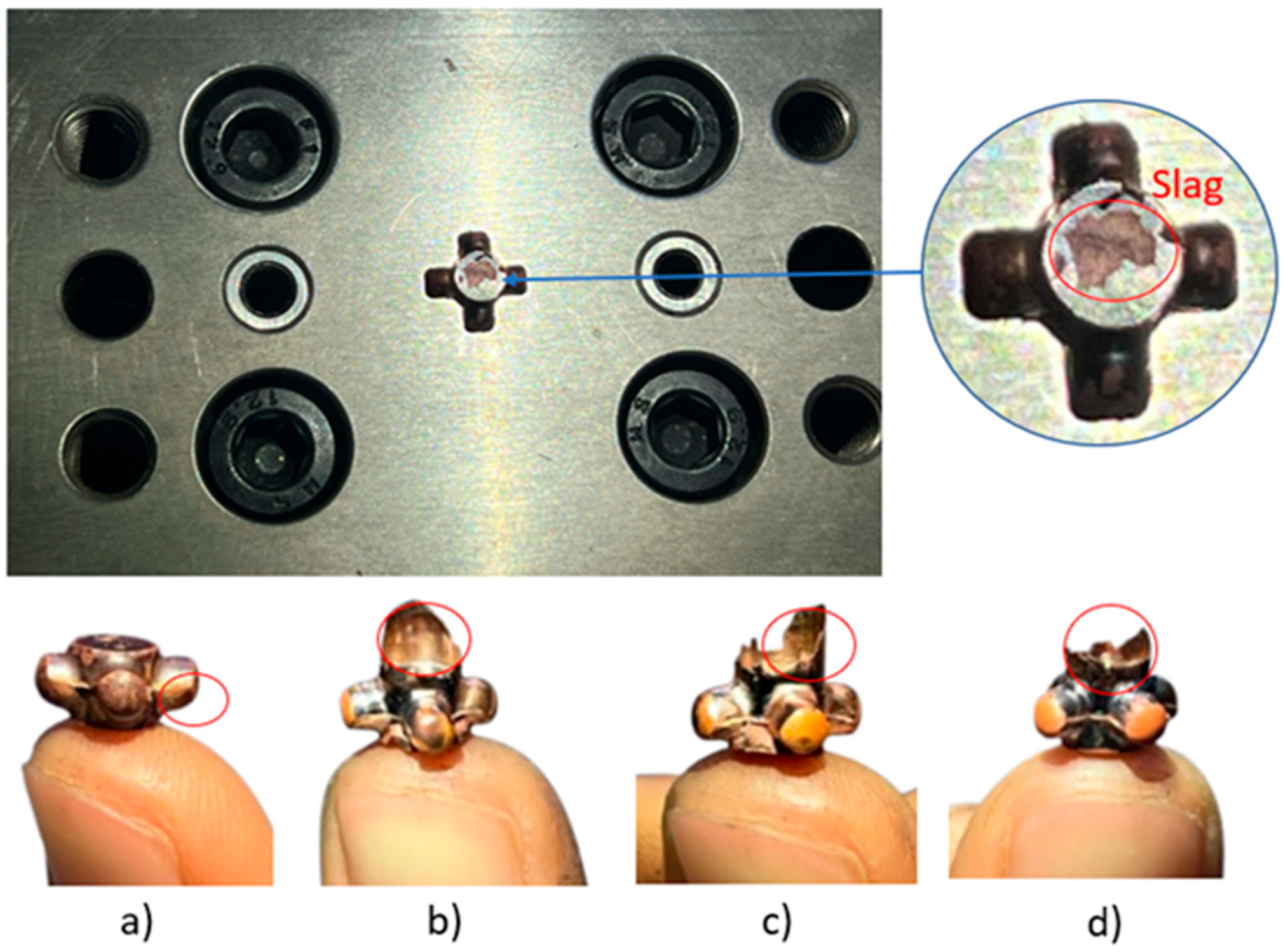
The results, as shown in Figure 15, effectively demonstrate the potential of micro-extrusion technology in manufacturing components with sophisticated shapes. Upon measuring the produced components, the following results were obtained: at a billet temperature of 350 °C, the branch height was h = 4.87 mm and the apex radius was R = 0.47 mm; at a billet temperature of 450 °C, the branch height and apex radius were 4.96 mm and 0.33 mm, respectively; at a billet temperature of 550 °C, the branch height and apex radius were 5.00 mm and 0.29 mm, respectively. Figure 16 provides a comparison between the experimental results and those obtained from numerical simulations, revealing that the branch height h meets the required product quality standards with an error margin of less than 5%. However, the apex radius R still does not meet the requirements. This was identified during the simulation, as this is the last region where the metal fills the mold, and the pressure in this area is extremely high, hindering the metal from completely filling the mold to form the component. The metal tends to flow backward into the die gap or fails to fully form the component before filling the entire mold, as specifically shown in Figure 17. This phenomenon can be explained based on the principle of minimum plastic resistance. Specifically, at the apex radius region (R), the deformation resistance reaches its maximum value, causing the material to flow toward areas with lower resistance. As a result, the material tends to flow backward into the gap between the punch and the die. In addition, factors such as the size effect, friction, and scale effect also significantly contribute to this phenomenon. This is considered one of the typical technical limitations of current micro-extrusion technology, which reduces its applicability in manufacturing fields that require ultra-small dimensions. Numerous studies have been conducted to address this issue. Notable solutions include the application of ultrasonic energy and magnetic field vibrations to enhance formability, as well as the use of more effective lubrication methods to reduce friction in the deformation zone [33,45]. It should be noted that in numerical simulations, the friction coefficient is commonly assumed to be constant. However, friction is highly dependent on contact pressure, temperature, and strain rate; thus, this assumption may introduce errors into the simulation results. Furthermore, heat losses from the billet to the environment and between the billet and the die also alter the thermo-mechanical state of the material during experiments. These factors help to explain the significant discrepancies observed between the simulation and experimental results, particularly at the apex radius (R). Some surface defects appeared on the product, with slag forming at the contact point between the billet surface and the punch. This occurred because the forming process is warm forming, and the billet was not kept in an inert atmosphere during the heating process, causing the surface material to oxidize when exposed to air. Additionally, in the micro-forming process, the size effect significantly influences the forming process, as the ratio of contact area to volume and the uneven distribution of heat also promote the formation of dross or slag during the forming process. Furthermore, it was observed that the higher the temperature, the better the material’s formability. In the 450 °C and 550 °C temperature range, the cross-shaped coupling exhibited sharper details and better dimensional accuracy compared to that in the 350 °C range.
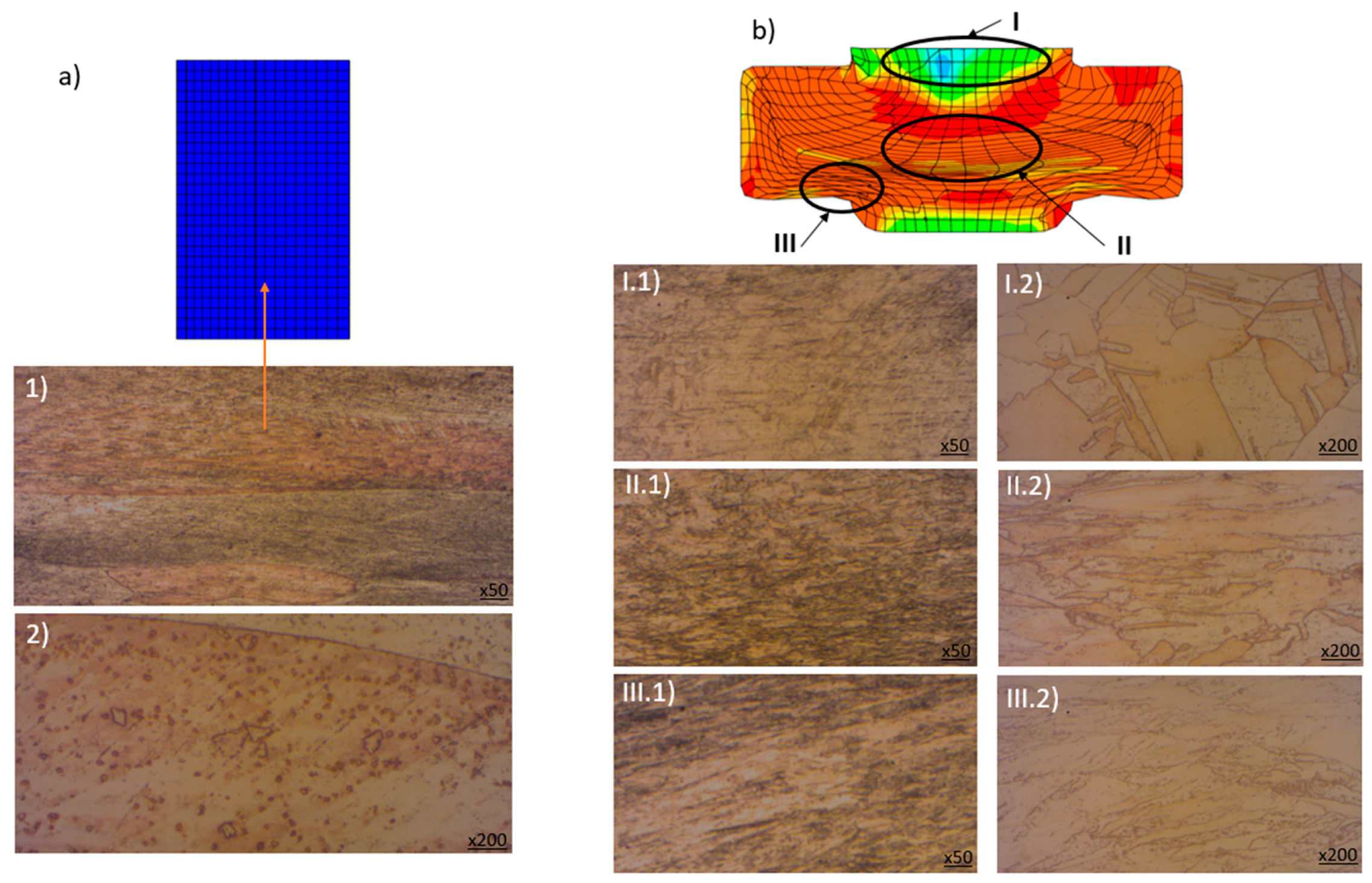
The investigation of the optical microstructure was conducted on the initial cylindrical billet and the cross-shaped coupling component formed by the micro-extrusion process. Figure 18 illustrates the observation results, where (1) denotes the micrograph at 50× magnification and (2) denotes the micrograph at 200× magnification. The formed part was divided into three primary observation zones: Zone I—the edge of the component, Zone II—the central region, and Zone III—the fillet area. Using a ZEISS Axiovert 100 A microscope (ZEISS, Oberkochen, Germany), we examined the microstructure of the samples to assess the grain structure evolution of pure copper under elevated temperatures during forming. The initial billet, produced from rolled copper, exhibited small, elongated grains oriented in the rolling direction, along with the appearance of some new grain nuclei. After the high-temperature micro-extrusion process, the material’s microstructure changed significantly across the different zones. The most deformed area, with grains elongated along the curvature, was Zone III (the fillet region). This was the flow gateway, where the material was subjected to intense pressure to form the coupling branches. Zone II (the central region) also experienced substantial deformation, leading to grain elongation due to central compressive stress. In contrast, Zone I (the edge of the flat region) underwent minimal deformation; the grains remained equiaxed and showed no preferential orientation, likely due to the low deformation and elevated temperature, which preserved the uniform grain structure. The entire forming process occurred within the plastic deformation range of pure copper and did not exceed the material’s fracture limit. The high-temperature forming conditions induced strain hardening—a phenomenon that significantly enhances the mechanical properties of the final product. Numerical simulation results also revealed significant deformation in Zones II and III, while Zone I experienced relatively low strain—correlating well with the experimental observations. This consistency confirms the reliability of the simulation model and highlights the improvement in mechanical performance as one of the key advantages offered by micro-extrusion technology.
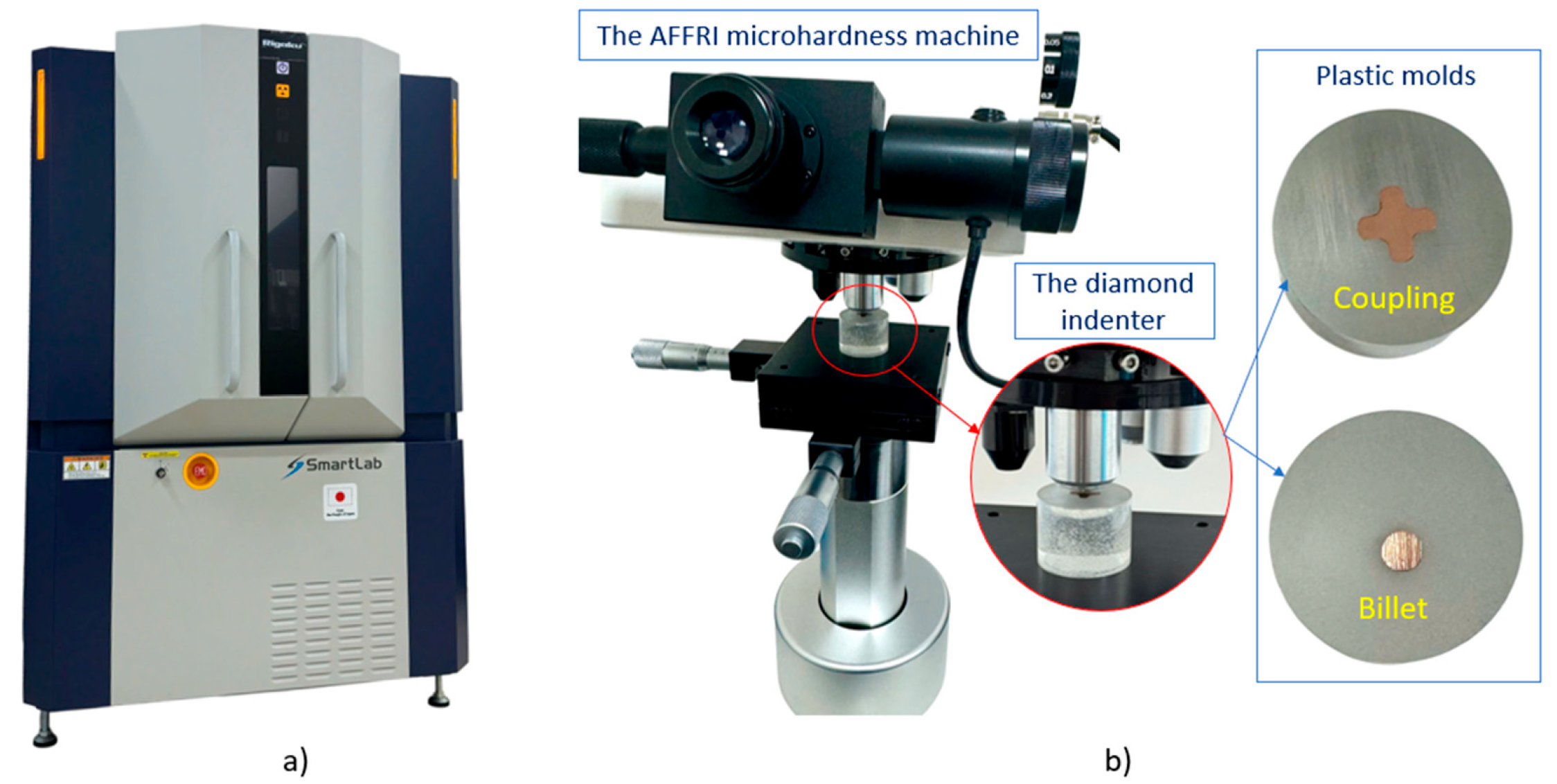
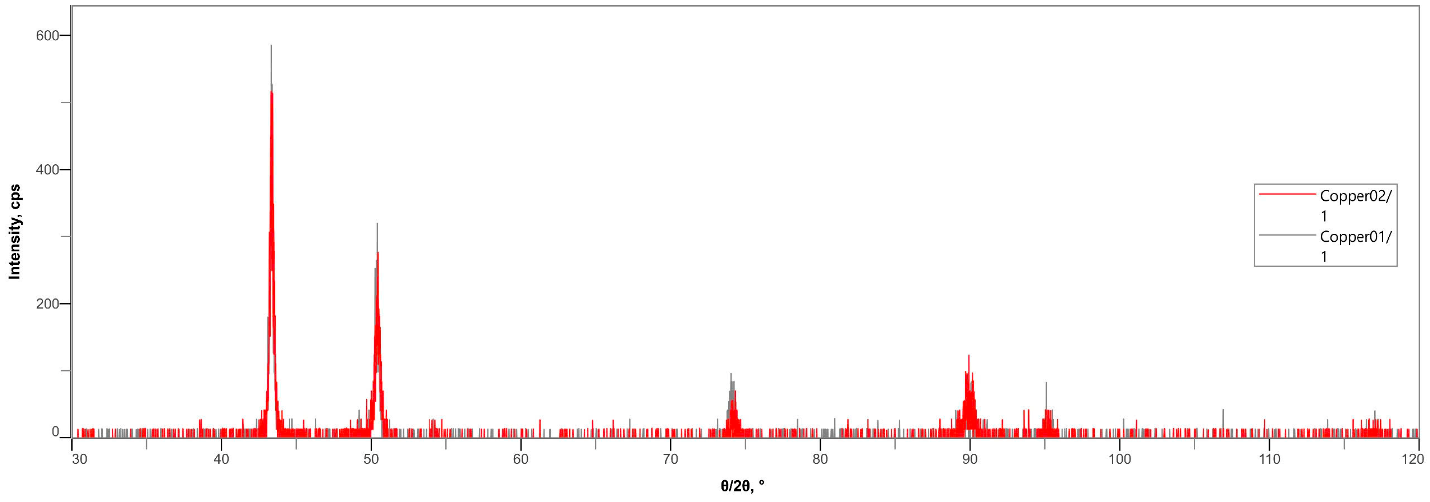
Figure 19 illustrates the experimental equipment, including the following: (a) the Rigaku SmartLab X-ray diffraction (XRD) system and (b) the AFFRI microhardness testing system. The XRD analysis procedure, as depicted in Figure 20, was conducted to examine the phase composition within the crystal structure of the material, comparing the initial billet and the post-formed product. In the diffraction pattern, the black curve represents the spectrum of the cross-shaped coupling product, while the red curve corresponds to that of the original cylindrical billet. The diffraction peaks indicate the presence of distinct crystalline phases. The results reveal a high degree of similarity between the two spectra, confirming that both the billet and the final product predominantly consist of the α-phase of copper. This phenomenon can be attributed to the fact that the forming process was conducted at temperatures near the recrystallization temperature of copper. At this temperature range, the thermal energy is insufficient to trigger significant phase transformations or alterations in the crystal lattice structure. As a result, the phase composition of the material remains unchanged throughout the forming process, thereby preserving the inherent physical and chemical properties of the original material. These findings further support the conclusion that the micro-extrusion technique does not degrade the material quality; on the contrary, it maintains a stable crystalline structure while enhancing mechanical properties through strain-hardening mechanisms.
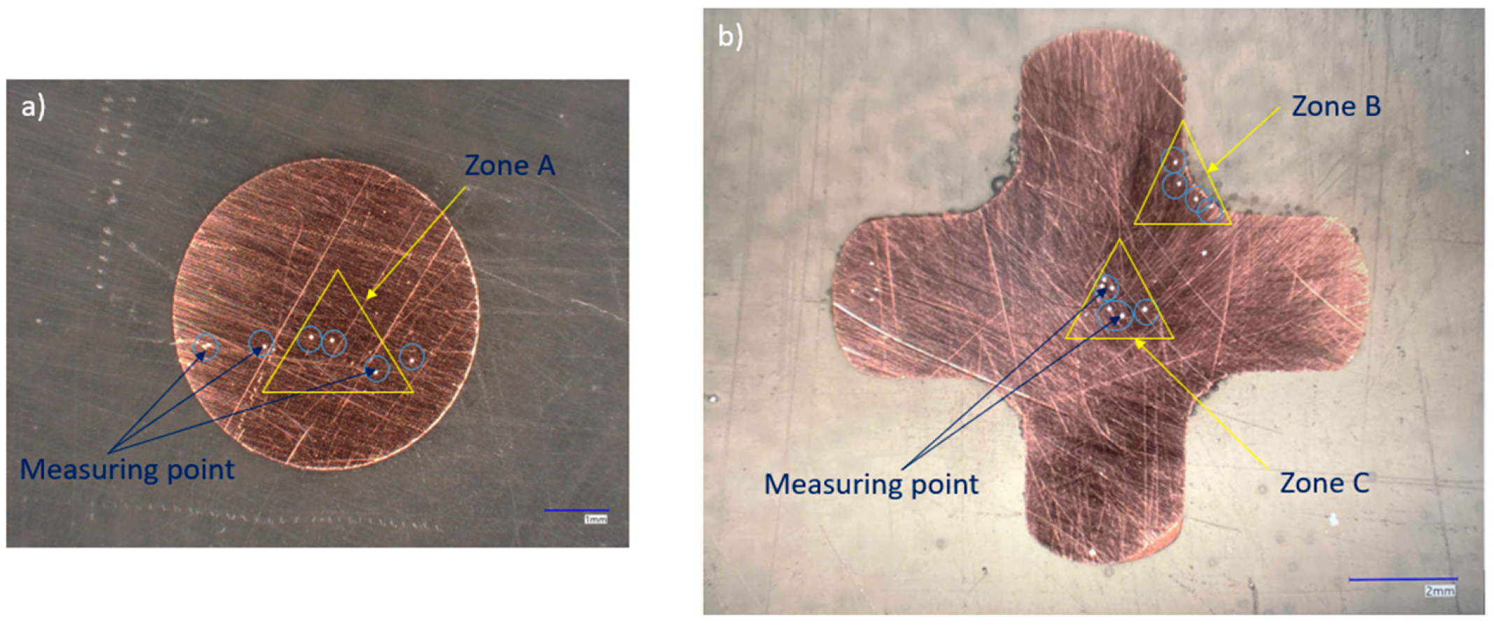
The quality of the post-formed product was evaluated through hardness measurements using the Vickers hardness test. The measurement procedure was conducted as follows: the surfaces of both the billet and the formed product were polished to achieve smoothness and then embedded in a plastic mold to create a rigid block for stable sample mounting. Subsequently, a diamond indenter with a pyramidal geometry was pressed into the sample surface under a specified load, creating indentations—representing the measurement points—as illustrated in Figure 21. The system, comprising an optical microscope, a sensor unit, and image-processing software, enabled precise identification and display of Vickers hardness (HV) at each measurement location.
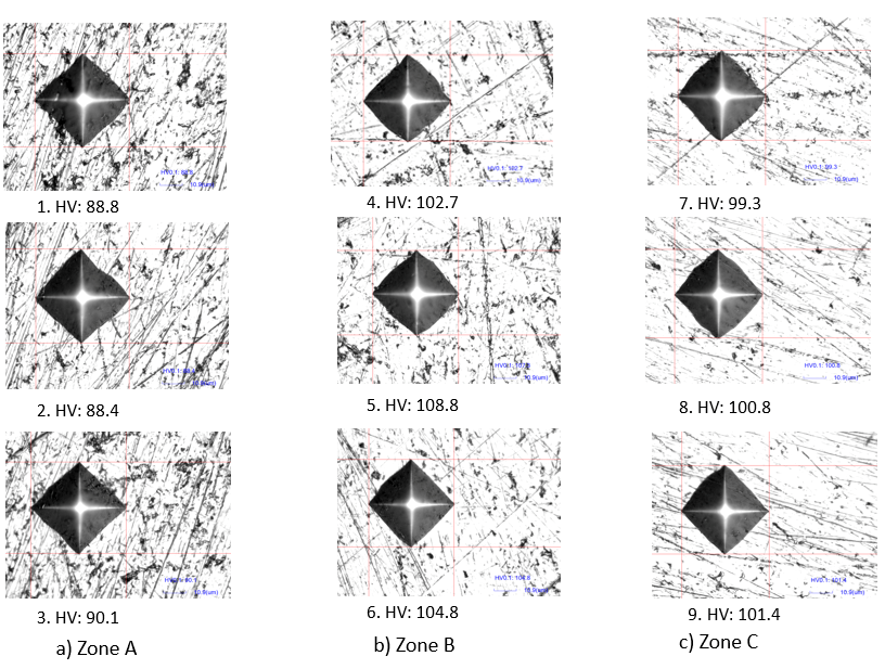
The results are presented in Table 4, along with micrographs of the indentations at various regions of the sample, shown in Figure 22. Specifically, Zone A corresponds to measurement points on the original cylindrical billet; Zone B refers to points located at the fillet area where the branches of the cross-shaped coupling are formed, and Zone C includes points at the central region of the part. The data indicate that Zones B and C exhibit higher hardness values compared to Zone A. This suggests that, under the influence of temperature and the micro-extrusion forming process, the product acquires enhanced mechanical properties, particularly in terms of hardness. Notably, Zone B—the branch section of the coupling—demonstrates the highest hardness values. This region typically experiences high stress during service and is prone to failure when using conventional manufacturing methods such as machining or welding. However, due to strain-hardening mechanisms activated during micro-extrusion, this region not only achieves superior hardness but also contributes to the overall strength of the component. This conclusion aligns with the earlier microstructural observations, in which Zone B exhibited the most pronounced grain elongation—an indicative feature of strain-induced hardening during plastic deformation.
To enhance formability in micro backward extrusion, advanced lubrication strategies are often employed, differing significantly from conventional forming processes that rely on lubricants such as oils, greases, or water. Instead, micro-forming techniques commonly utilize specialized approaches, including ultrasonic vibration, magnetic assistance, or die heating, to effectively reduce friction and improve material flow. In future research, the formability of the micro backward extrusion process will be further improved by integrating ultrasonic vibration and die heating, with the objective of achieving the desired apex radius dimension in the formed components.

4. Conclusions

This study focuses on analyzing the influence of friction and temperature on the forming process, formability, forming force, and the standard of the final product in the micro-extrusion of commercially pure copper. By integrating numerical simulation with experimental validation, the research establishes a solid theoretical foundation while concurrently verifying and explaining key technical phenomena. The findings highlight several critical observations:
The effects of friction and temperature on the forming force are clearly demonstrated. Specifically, when the friction coefficient increases from 0.05 to 0.5 at billet temperatures of 350 °C, 450 °C, and 550 °C, the forming force increases by 384.5%, 324.16%, and 301.96%, respectively. Meanwhile, raising the billet temperature from 350 °C to 750 °C results in a reduction of the forming force by up to 78.6%.
Numerical simulations successfully predict the most critical regions in terms of formability on the cross-shaped coupling, particularly at the apex radius R—the area subject to the highest internal pressure. In this zone, the material tends to flow backward toward the punch-die clearance before completely filling the die cavity, thus posing challenges to achieving full shape.
Experimental results reveal that the branch height h is reproduced with high accuracy, maintaining an error below 5%. However, the targeted radius R at the apex is not fully attained under the current experimental conditions. Additionally, the study identifies a billet temperature of approximately 550 °C as the optimal processing window for micro-extrusion.
Microstructural evaluation indicates that under the influence of elevated temperature, the mechanical properties of the material are enhanced due to strain hardening. In Zone III, the grains exhibit significant deformation and are oriented along the curvature, whereas in Zone I, the grains undergo minimal deformation and are distributed equixially.
The XRD results reveal that while the phase composition remains unchanged, the crystal structure (texture and dislocation density) was modified by plastic deformation and strain-hardening mechanisms, leading to a significant improvement in the mechanical properties, particularly hardness. In Region B—the fillet area where the product branch is formed—the grains exhibit elongated orientation and the highest hardness values, reflecting the effectiveness of the micro-extrusion process.
In future research, advanced lubrication methods—such as the use of ultrasonic energy, magnetic fields, or die heating—will be explored to enhance the formability and surface quality of cross-shaped coupling components. Furthermore, expanding the scope of research to include other materials such as aluminum, titanium, and alloy steels will also be a key direction in the upcoming studies. This research not only underscores the critical role of micro-extrusion technology in manufacturing high-precision small-scale components but also extends the potential applicability of micro-forming to complex bulk geometries.

Author Contributions

Data curation, T.M.T.; investigation, T.M.T. and M.-Q.N.; methodology, T.N.T.; supervision, T.N.T.; writing—original draft, T.M.T.; writing—review and editing, M.-Q.N. and T.N.T. All authors have read and agreed to the published version of the manuscript.

Funding

This research was funded by Hanoi University of Science and Technology (HUST) under project number T2023-PC-006.

Institutional Review Board Statement

Not applicable.

Informed Consent Statement

Not applicable.

Data Availability Statement

The original contributions presented in this study are included in the article. Further inquiries can be directed to the corresponding authors.

Acknowledgments

This research was funded by Hanoi University of Science and Technology (HUST) under project number T2023-PC-006.

Conflicts of Interest

The authors declare no conflict of interest.

References

  1. Manabe, K.-i. Metal Micro-Forming. Metals 2020, 10, 813. [Google Scholar] [CrossRef]
  2. De Pasquale, G. Additive Manufacturing of Micro-Electro-Mechanical Systems (MEMS). Micromachines 2021, 12, 1374. [Google Scholar] [CrossRef]
  3. Gaspar-Cunha, A.; Covas, J.A.; Sikora, J. Optimization of Polymer Processing: A Review (Part I—Extrusion). Materials 2022, 15, 384. [Google Scholar] [CrossRef]
  4. Pricci, A.; de Tullio, M.D.; Percoco, G. Analytical and Numerical Models of Thermoplastics: A Review Aimed to Pellet Extrusion-Based Additive Manufacturing. Polymers 2021, 13, 3160. [Google Scholar] [CrossRef]
  5. Xu, J.; Wang, X.; Wang, C.; Yuan, L.; Chen, W.; Bao, J.; Su, Q.; Xu, Z.; Wang, C.; Wang, Z.; et al. A Review on Micro/Nanoforming to Fabricate 3D Metallic Structures. Adv. Mater. 2021, 33, e2000893. [Google Scholar] [CrossRef] [PubMed]
  6. Li, Y.; Feng, L.; Kang, F.; Du, H.; Chen, Z. Recent research and advances in extrusion forming of magnesium alloys: A review. J. Alloys Compd. 2023, 953, 170080. [Google Scholar] [CrossRef]
  7. Preedawiphat, P.; Mahayotsanun, N.; Sucharitpwatskul, S.; Funazuka, T.; Takatsuji, N.; Bureerat, S.; Dohda, K. Finite Element Analysis of Grain Size Effects on Curvature in Micro-Extrusion. Appl. Sci. 2020, 10, 4767. [Google Scholar] [CrossRef]
  8. Rahman, J.; Quodbach, J. Versatility on demand—The case for semi-solid micro-extrusion in pharmaceutics. Adv. Drug Deliv. Rev. 2021, 172, 104–126. [Google Scholar] [CrossRef]
  9. Askari, M.; Naniz, M.A.; Kouhi, M.; Saberi, A.; Zolfagharian, A.; Bodaghi, M. Recent progress in extrusion 3D bioprinting of hydrogel biomaterials for tissue regeneration: A comprehensive review with focus on advanced fabrication techniques. Biomater. Sci. 2020, 9, 535–573. [Google Scholar] [CrossRef]
  10. Strano, M.; Rane, K.; Farid, M.A.; Mussi, V.; Zaragoza, V.; Monno, M. Extrusion-based additive manufacturing of forming and molding tools. Int. J. Adv. Manuf. Technol. 2021, 117, 2059–2071. [Google Scholar] [CrossRef]
  11. Chen, D.; Wang, Y.; Zhou, H.; Huang, Z.; Zhang, Y.; Guo, C.; Zhou, H. Current and Future Trends for Polymer Micro/nano Processing in Industrial Applications. Adv. Mater. 2022, 34, e2200903. [Google Scholar] [CrossRef] [PubMed]
  12. Tabaa, M.; Monteiro, F.; Bensag, H.; Dandache, A. Green Industrial Internet of Things from a smart industry perspectives. Energy Rep. 2020, 6, 430–446. [Google Scholar] [CrossRef]
  13. Vollertsen, F. (Ed.) Introduction. In Micro Metal Forming; Springer: Berlin/Heidelberg, Germany, 2013; pp. 1–3. [Google Scholar] [CrossRef]
  14. Zheng, J.-Y.; Shi, S.Q.; Fu, M.W. Progressive microforming of pin-shaped plunger parts and the grain size effect on its forming quality. Mater. Des. 2020, 187, 108–386. [Google Scholar] [CrossRef]
  15. Zhang, B.; Dodaran, M.; Ahmed, S.; Shao, S.; Meng, W.J.; Juul, K.J.; Nielsen, K.L. Grain-size affected mechanical response and deformation behavior in microscale reverse extrusion. Materialia 2019, 6, 100272. [Google Scholar] [CrossRef]
  16. Rajenthirakumar, D.; Srinivasan, N.; Sridhar, R. Kumar, R., Chauhan, V.S., Talha, M., Pathak, H., Eds.; Development of a Micro-forming System for Micro-extrusion Process of Micro-pin in AZ80 Alloy. In Machines, Mechanism and Robotics. Lecture Notes in Mechanical Engineering 2022; Springer: Singapore, 2022. [Google Scholar] [CrossRef]
  17. Liu, Y.; Xu, J.; Zhang, Z.; Liu, G.; Shan, D.; Zhang, L.; Guo, B. Micro-Extrusion Process and Microstructure Evolution of Miniature Heat Pipe in 6063 Aluminum Alloy. Int. J. Adv. Manuf. Technol. 2022, 120, 6463–6480. [Google Scholar] [CrossRef]
  18. Kiswanto, G.; Supriadi, S.; Dwiyati, S. Challenge in magnesium microforming. IOP Conf. Ser. Mater. Sci. Eng. 2021, 1070, 012121. [Google Scholar] [CrossRef]
  19. Abd-Elaziem, W.; Hamada, A.; Makino, T.; Hassan, M.A. Microstructural evolution during extrusion of equal channel angular-pressed AA1070 alloy in micro/mesoscale. Mater. Sci. Technol. 2020, 36, 1169–1177. [Google Scholar] [CrossRef]
  20. Nanthakumar, S.; Rajenthirakumar, D.; Avinashkumar, S. Influence of temperature on deformation behavior of copper during microextrusion process. Proc. Inst. Mech. Eng. Part C J. Mech. Eng. Sci. 2020, 234, 095440621989911. [Google Scholar] [CrossRef]
  21. Du, H.-q.; Li, F.; Huo, P.-d.; Wang, Y. Microstructure evolution and ductility improvement mechanisms of magnesium alloy in interactive alternating forward extrusion. Trans. Nonferrous Met. Soc. China 2022, 32, 2557–2568. [Google Scholar] [CrossRef]
  22. Yan, X.; Zhang, S.; Huang, K.; Yang, Y.; Wang, W.; Wu, M. Effect of Holding Time on the Extrusion Force and Microstructure Evolution during the Plastic Forming of Ti-6Al-4V Micro-Gears. Materials 2022, 15, 1507. [Google Scholar] [CrossRef]
  23. Venkatesh, B.; Sahoo, S.K.; Panigrahi, S.K. Micro-extrusion: A potential approach to micro-manufacture miniaturize magnesium metal matrix composite components. J. Manuf. Process. 2024, 131, 2473–2490. [Google Scholar] [CrossRef]
  24. Wan, W.; Lv, P.; Liu, F.; Xu, L.; Bai, W.; Han, G. Evaluation of interfacial friction characteristics in multi-mode ultrasonic vibration assisted micro-extrusion process. J. Manuf. Process. 2023, 88, 12–21. [Google Scholar] [CrossRef]
  25. Venkatesh, B.; Panigrahi, S.K. A superplastic micro-extrusion technology to develop engineered magnesium micro-components. J. Mater. Process. Technol. 2024, 327, 118350. [Google Scholar] [CrossRef]
  26. Slámečka, K.; Drotárová, L.; Oliver-Urrutia, C.; Tkachenko, S.; Remešová, M.; Gejdoš, P.; Čelko, L.; Montufar, E.B. Low-temperature gas nitriding effects on mechanical and biological properties of open-porous pure titanium produced by robotic micro-extrusion. Surf. Coat. Technol. 2025, 505, 132084. [Google Scholar] [CrossRef]
  27. Zhou, M.; Li, M.; Jiang, J.; Li, Y.; Liu, H.; Chen, B.; Zhao, D.; Zhai, W. Porous polyetherimide fiber fabricated by a facile micro-extrusion foaming for high temperature thermal insulation. J. CO2 Util. 2022, 65, 102247. [Google Scholar] [CrossRef]
  28. Wan, W.; Han, G.; Liu, F.; Hu, J.; Xu, L.; Bai, W.; Chen, H. Surface and volume effects in multimodal ultrasonic vibration assisted micro-extrusion forming: Experiments and modelling. J. Mater. Process. Technol. 2023, 322, 118185. [Google Scholar] [CrossRef]
  29. Li, S.; Han, K.; Gao, F.; Shi, H.; Song, H.; Zhang, Y.; An, C. Research on the performance of high-strength explosive ink and application of direct writing technology in micro-explosive network. Mater. Today Commun. 2024, 41, 110630. [Google Scholar] [CrossRef]
  30. Ehrmann, G.; Blachowicz, T.; Ehrmann, A. Magnetic 3D-Printed Composites—Production and Applications. Polymers 2022, 14, 3895. [Google Scholar] [CrossRef] [PubMed]
  31. Trzepieciński, T.; Najm, S.M.; Sbayti, M.; Belhadjsalah, H.; Szpunar, M.; Lemu, H.G. New Advances and Future Possibilities in Forming Technology of Hybrid Metal–Polymer Composites Used in Aerospace Applications. J. Compos. Sci. 2021, 5, 217. [Google Scholar] [CrossRef]
  32. Sharma, S.; Kodli, B.; Saxena, K. Micro Forming and its Applications: An Overview. Key Eng. Mater. 2022, 924, 73–91. [Google Scholar] [CrossRef]
  33. Han, G.; Wan, W.; Zhang, Z.; Xu, L.; Liu, F.; Zhang, H. Experimental investigation into effects of different ultrasonic vibration modes in micro-extrusion process. J. Manuf. Process. 2021, 67, 427–437. [Google Scholar] [CrossRef]
  34. Li, W.; Zhou, Z.; Zhang, B.; Xiao, Y. A micro-coupling for micro mechanical systems. Chin. J. Mech. Eng. 2016, 29, 571–578. [Google Scholar] [CrossRef]
  35. Mehta, G.; Kumar, R.; Shelare, S.; Pachpor, A.; Sharma, S.; Kumar, S.; Bisht, Y.; Abbas, M. Unravelling the Dynamics of Misalignment-Induced Vibrations in Two Jaw Elastomeric Couplings for Enhanced Industrial Reliability: A Comprehensive Analysis of Dynamics and Diagnostic Approaches. J. Vib. Eng. Technol. 2024, 12, 413–426. [Google Scholar] [CrossRef]
  36. Eloy, J.; Mounier, E. Status of the MEMS industry. In Proceedings of the MEMS/MOEMS Components and Their Applications II, San Jose, CA, USA, 24–25 January 2005. [Google Scholar] [CrossRef]
  37. Chen, T.; Wen, M.; Cui, H.; Guo, J.; Wang, C. Hot Deformation Behavior and Processing Maps of Pure Copper during Isothermal Compression. Materials 2023, 16, 3939. [Google Scholar] [CrossRef]
  38. Kuhfuss, B. Bulk Metal Forming. In Micro Metal Forming; Vollertsen, F., Ed.; Springer: Berlin/Heidelberg, Germany, 2013; p. 125. [Google Scholar] [CrossRef]
  39. Sucharitpwatskul, S.; Mahayotsanun, N.; Bureerat, S.; Dohda, K. Effects of Tool Coatings on Energy Consumption in Micro-Extrusion of Aluminum Alloy 6063. Coatings 2020, 10, 381. [Google Scholar] [CrossRef]
  40. Wan, W.; Cheng, J.; Xu, L.; Liu, F.; Zhang, H.; Han, G. Investigation on friction characteristics of micro double cup extrusion assisted by different ultrasonic vibration modes. Int. J. Adv. Manuf. Technol. 2022, 123, 2549–2560. [Google Scholar] [CrossRef]
  41. Aruchamy, K.; Rajenthirakumar, D.; Arunkumar, M. Microforming: Exploring the role of temperature and forming die in deformation behavior of AL6063 in forward microextrusion. J. Alloys Compd. Commun. 2025, 7, 100092. [Google Scholar] [CrossRef]
  42. Su, Z.; Zhu, Z.; Zhang, Y.; Zhang, H.; Xiao, Q. Recrystallization Behavior of a Pure Cu Connection Interface with Ultrasonic Welding. Metals 2020, 11, 61. [Google Scholar] [CrossRef]
  43. Hosford, W.; Caddell, R. Metal Forming Mechanics and Metallurgy; Cambridge University Press: Cambridge, UK, 2011. [Google Scholar]
  44. William, D.; Callister, D.G.R. Materials Science and Engineering: An Introduction, 10th ed.; Wiley: Hoboken, NJ, USA, 2018. [Google Scholar]
  45. Nanthakumar, S.; Thangaraju, D.; Avinash Kumar, R.K. Experimental investigation of 2D-SnS 2 hexagonal nanosheets as lubricating additive in the microextrusion process. Proc. Inst. Mech. Eng. Part C J. Mech. Eng. Sci. 2022, 237, 095440622211236. [Google Scholar] [CrossRef]
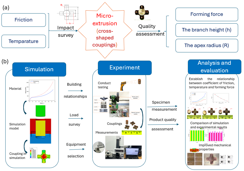
Figure 1. Summary diagram: (a) objectives and processes; (b) research.
Eng 06 00250 g001
Figure 2. Drawing (a) and image (b) of the original workpiece dimensions.
Eng 06 00250 g002
Figure 3. 2D drawing of the cross-shaped coupling.
Eng 06 00250 g003
Figure 4. Universal compression machine (a) and specimens (b).
Eng 06 00250 g004
Figure 5. Results of uniaxial compression tests: (a) load−displacement curve; (b) stress−strain curves of pure copper.
Eng 06 00250 g005
Figure 6. Construction hardening laws for the material.
Eng 06 00250 g006
Figure 7. Numerical simulation model setup in the ABAQUS software (a), deformable mesh (b), and cross-shaped coupling forming process in the simulation (c).
Eng 06 00250 g007
Figure 8. Schematic (a) and image (b) of the experimental model.
Eng 06 00250 g008
Figure 9. Results of numerical simulations regarding variations in the friction coefficient at 350 °C.
Eng 06 00250 g009
Figure 10. Results of numerical simulations regarding variations in the friction coefficient at 350 °C, 450 °C, and 550 °C.
Eng 06 00250 g010
Figure 11. Forming force curve when friction changes.
Eng 06 00250 g011
Figure 12. Numerical simulation results when changing the workpiece temperature.
Eng 06 00250 g012
Figure 13. Forming force curve when changing the workpiece temperature.
Eng 06 00250 g013
Figure 14. Contour measuring system: Contracer CV-2100 Series (Mitutoyo, Kawasaki-shi, Japan).
Eng 06 00250 g014
Figure 15. Some cross-shaped coupling products in the experiment.
Eng 06 00250 g015
Figure 16. Comparison graph of simulation results and experimental results.
Eng 06 00250 g016aEng 06 00250 g016b
Figure 17. Some defects of cross-shaped coupling. (a) Branch not filled (b) Burrs forming behind (c) Burrs forming on the right (d) Burrs forming around.
Eng 06 00250 g017
Figure 18. Some optical micrographs of pure copper: (a) initial cylindrical billet sample; (b) cross-shaped coupling after micro-extrusion.
Eng 06 00250 g018
Figure 19. (a) X-ray diffractometer; (b) hardness-measuring system.
Eng 06 00250 g019
Figure 20. X-ray diffraction pattern of the pure copper material.
Eng 06 00250 g020
Figure 21. Location of hardness measurement points: (a) billet; (b) coupling.
Eng 06 00250 g021
Figure 22. Microscopic images of hardness measurement points in different zones.
Eng 06 00250 g022
Table 1. Chemical composition of C11000.
MaterialComposition (%)
C11000 Cu > 99.8Mn < 0.001Bi < 0.001As < 0.001Fe < 0.001Ni < 0.001
Table 2. Calculating parameters of the hardening laws for C11000.
Hardening LawHollomonLudwikVoce
ParametersK (MPa)nK (MPa) σ 0 (MPa)n σ s (MPa) σ o (MPa)b
Value30640.99810,961418.52.804743,891134.990.00356
Table 3. Mechanical properties of C11000.
MaterialC11000
Density   ( ρ , kg/m3)8.96 × 10−6
Elastic modulus (E, kN/mm2)69
Poisson coefficient0.34
Specific   heat   capacity   ( J / k g ) 385
Thermal conductivity (W/mK)379 (at 550 °C)
Linear coefficient of expansion17.1 × 10−6/°C
Table 4. Hardness values in zones.
No.Hardness Value (HV)
Zone AZone BZone C
188.8102.799.3
288.4107.3100.8
390.1104.8101.4
AVG.89.1104.9100.5
Disclaimer/Publisher’s Note: The statements, opinions and data contained in all publications are solely those of the individual author(s) and contributor(s) and not of MDPI and/or the editor(s). MDPI and/or the editor(s) disclaim responsibility for any injury to people or property resulting from any ideas, methods, instructions or products referred to in the content.