1. Introduction
The present case study concerns a vertical transfer device (VTD) hoisting shaft failure and redesign. The shaft steel is 34CrNiMo6. The size of the machine is suggested by the hoisting stroke—10 m. The machine operation began in 2017, and until 2019, malfunctions of the upper sprocket assembly were reported by the customer. During that period, the hoisting shaft fractured and was replaced by another equal in size and material. Sometime after this replacement, the customer noticed an abnormal play between the shaft and the sprocket on the key area. At the beginning of 2019, it was decided to investigate the root cause of this abnormal behaviour. At the end of 2019, the upper sprocket assembly was replaced by a redesigned one according to the conclusions of the present document, and no more problems were found since this intervention.
The service loads acting upon hoisting shafts typically lead to a number of cycles in excess of 107, implying fatigue design for infinite life under rotating bending and torsional loading.
The need for a thorough understanding of the machine operating cycle, so that wrong premises are not assumed for the fatigue design calculations, is emphasised in this paper.
Stress-based high-cycle fatigue (HCF) considerations are used throughout the work, and a classical approach to fatigue was adopted. Harris and Jur recall in [
1] that ‘the long-taught classical methodology is useful and accurate as both a design and an analysis tool’. The classical fatigue methodology is presented in many references, e.g., Childs [
2,
3], Beswarick [
4,
5] or D’Angelo [
6], and is widely used in industry, for design as well as for failure analyses, where interpretation of failure causes and redesign of failed parts are objectives to be pursued [
7].
Milela [
8] or Lee et al. [
9] present comprehensive overviews of fatigue, and discuss research on biaxial fatigue as experienced in situations of combined bending and torsion moments, typical of shafts. A survey of recent trends of multiaxial fatigue is given by Anes et al. [
10]. Although shaft fatigue is the object of continued research efforts, in the present work, the classical approach commonly used in industry was used for the redesign of a failed shaft subjected to high-cycle fatigue (HCF). Early presentations of the subject are found in, e.g., d’Isa [
11], Hall et al. [
12] or Spotts [
13].
The paper is organized as follows: the VTD operation mode is thoroughly analysed and modelled in
Section 2, as a starting point for the hoisting shaft redesign. After a presentation of the VTD mode of operation, the radial load, bending and torsional moments variations along the operating cycle are evaluated, and transients as emergency stop loads are characterized, leading to the inputs for the design calculations and selection of safety and duty cycle factors, as discussed in
Section 3.
Using the static failure criterion, a first sizing for the peak load is presented in
Section 4. Then, using the normal operation loads calculated in
Section 5, a fatigue design using different approaches is presented in
Section 6,
Section 7 and
Section 8.
The areas with keyseats are particularly sensitive in fatigue calculation. The use of steels with higher tensile strength does not proportionally increases the fatigue allowable in keyseat areas.
Given the organization of the work, relevant references are introduced and discussed throughout the text, as needed. Due to the large number of variables considered, their definitions are given in the Nomenclature of the document, and/or when called for in the text.
2. Detailed Analysis of the Vertical Transfer Device Operation Cycle
Vertical transfer devices are under the scope of the standard EN 619:2002+A1:2010 [
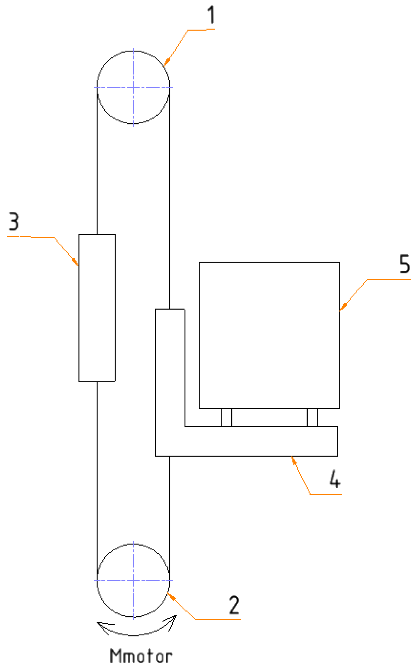
14] (EN 619:2002+A1:2010 has a new edition in 2022, not yet harmonised; only the harmonised standards can be used to demonstrate that products comply with the relevant European legislation), where the machine safety requirements are defined. According to this standard, a VTD is a device with raising and lowering movements of more than 200 mm in the path of conveyors, in which unit loads (in logistics terminology, a unit load corresponds to the pallet plus the handled goods) can be transferred from one defined level to one or more defined levels by a carrying element. The hoisting system of the VTD analysed is composed of a driving motorized sprocket on the bottom and a driven sprocket on the top. The suspension consists of one chain that is anchored to the hoisting carriage on one side and a counterweight on the other side; refer to
Figure 1 for more details. One conveyor is assembled on the hoisting carriage, and it is responsible for the transfer of the unit load to the grounded conveyors on each transfer level.
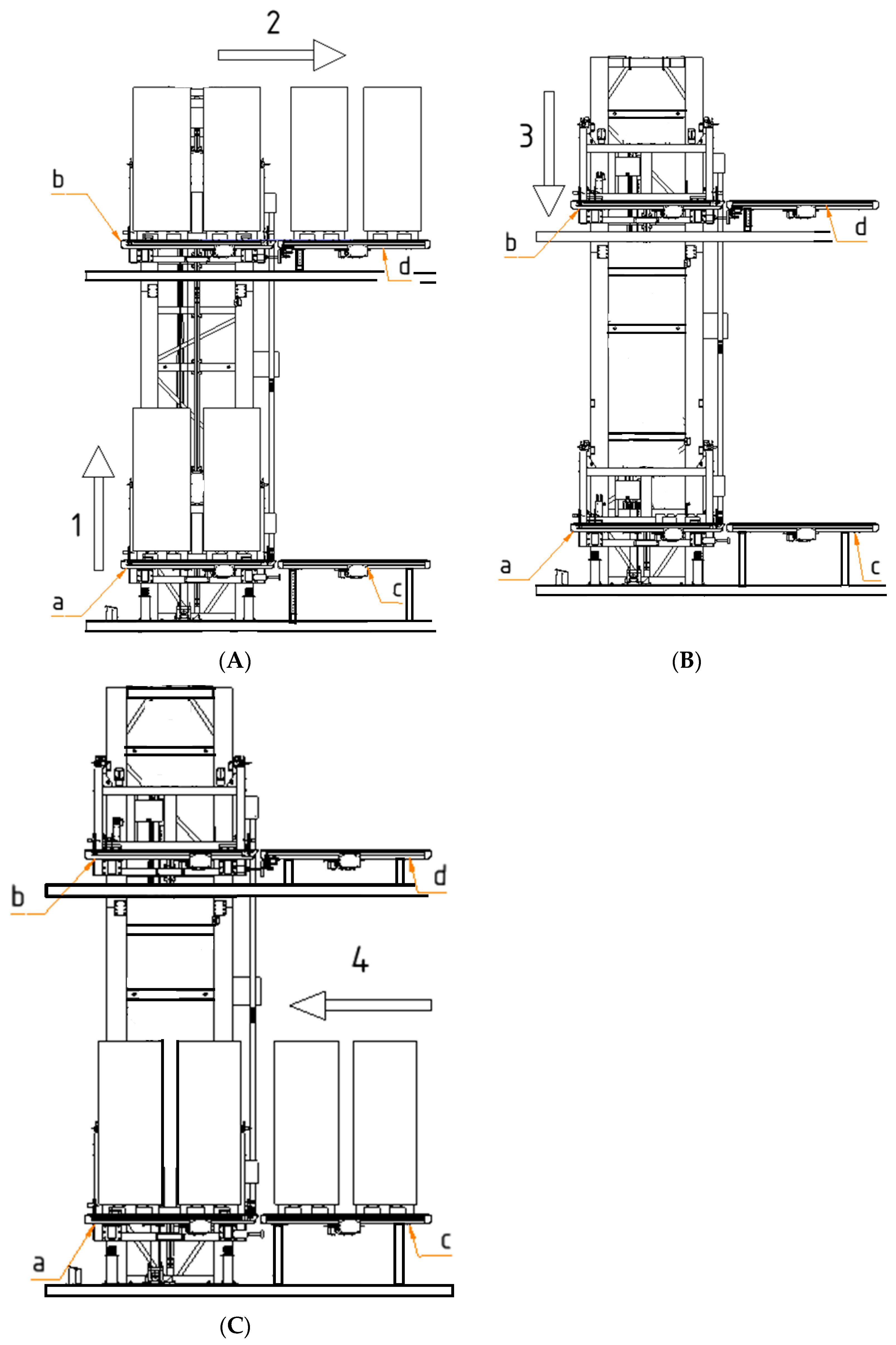
In this VTD, the hoisting stroke is 10 m, and the operating cycle consists of the steps described in
Figure 2, repeated 24 h/day.
Figure 3 presents the evolution of the VTD carriage hoisting speed (m/s) with time (s).
The operating cycle steps are:
1—Upward movement of the hoisting carriage with load on the conveyor,
Figure 2A. According to
Figure 3, from 0 s up to 3.25 s, the hoisting carriage accelerates, reaching the speed of 1.3 m/s. Between 3.25 s and 7.69 s, the hoisting carriage will move upward at a constant speed, followed by a 3.25 s deceleration.
2—Transfer of the load from the conveyor mounted on the hoisting carriage, to the grounded conveyor on the upper level,
Figure 2B. This transfer movement will take 10 s. During this time, the hoisting carriage is stopped.
3—Downward movement of the hosting carriage from the upper level to level 0,
Figure 2B. This movement will start at 20.94 s and is composed of an acceleration of 3.25 s, followed by a constant speed movement of 4.44 s, and finally, a 3.25 s deceleration.
4—The load will be transferred from the grounded conveyor at level zero, to the conveyor mounted on the hoisting carriage, which is stopped. This transfer will take 10 s,
Figure 2C.
Speeds and acceleration values in these machines are not prescribed. Instead, the design of the device, of its components and safety devices must be rooted in those values: the EN 619:2002+A1:2010 standard [
14] does not define maximum speeds and accelerations for the VTD, but states that the safety related components must be selected according to the effective nominal speed and acceleration of the machine.
The upper sprocket assembly, which is the object of the present case study, is shown in
Figure 4. It is composed of one shaft, two plummer blocks with roller bearings and one sprocket for the hoisting chain. Note that the failed shaft diameter was 50.0 mm.
The failure motivated the need for component redesign. As discussed in the following sections, a thorough understanding of the machine’s operating mode is necessary for the selection of inputs to calculate the redesigned shaft diameter.
3. Assumptions for Calculation and Safety Factors
This section presents the selection of data to be used as inputs when calculating the shaft diameter and selecting the safety factors.
Table 1 compiles the data for the case study system.
The load efficiency—
= 0.9—is the value advised by [
15] for the efficiency of sprocket-chain hoisting systems, as some amount of the gearmotor output torque is not used to hoist the load, but to compensate friction losses, for instance.
The data for the gearmotor were retrieved from [
15,
16] and are compiled in
Table 2.
Unless there are problems associated with bearings, which is unlikely if these are properly selected and fitted according to the applicable tolerances, in these constructions, the likely cause of shaft failure is fatigue. Corrosion is excluded, given the shaft surface protection by phosphating surface treatment, and the machine’s permanent location inside the warehouse.
A first check of the bearing life showed that the bearings were correctly chosen, and accordingly, bearing calculation and selection will be outside the scope of this paper. Since the failure was not related to the bearings, it was decided to further investigate the shaft design with a view to redesign. Given the level of responsibility involved, several calculation methods were used, and the results compared, to decrease the risk level.
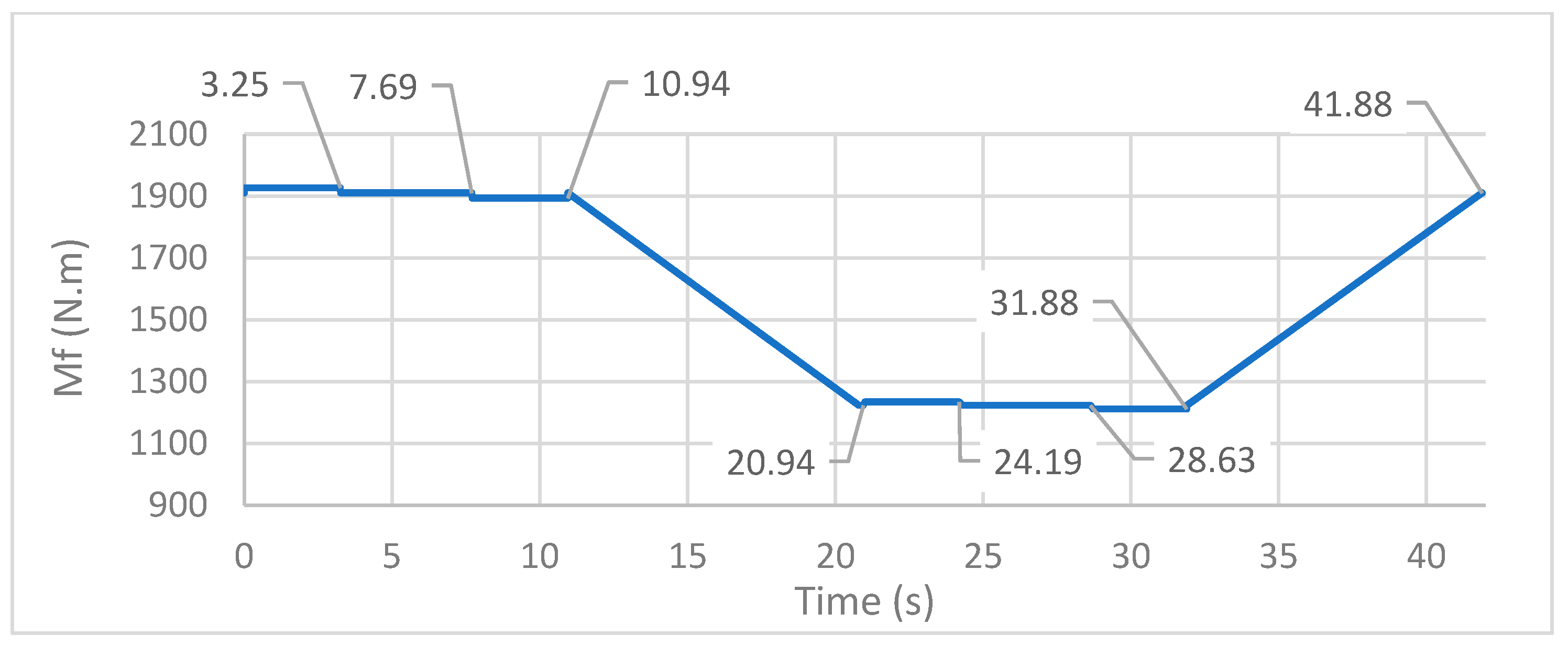
Firstly, it was necessary to carefully define the assumptions for the calculation. The bending and torsion moments and the radial load to be considered for the design calculations were evaluated.
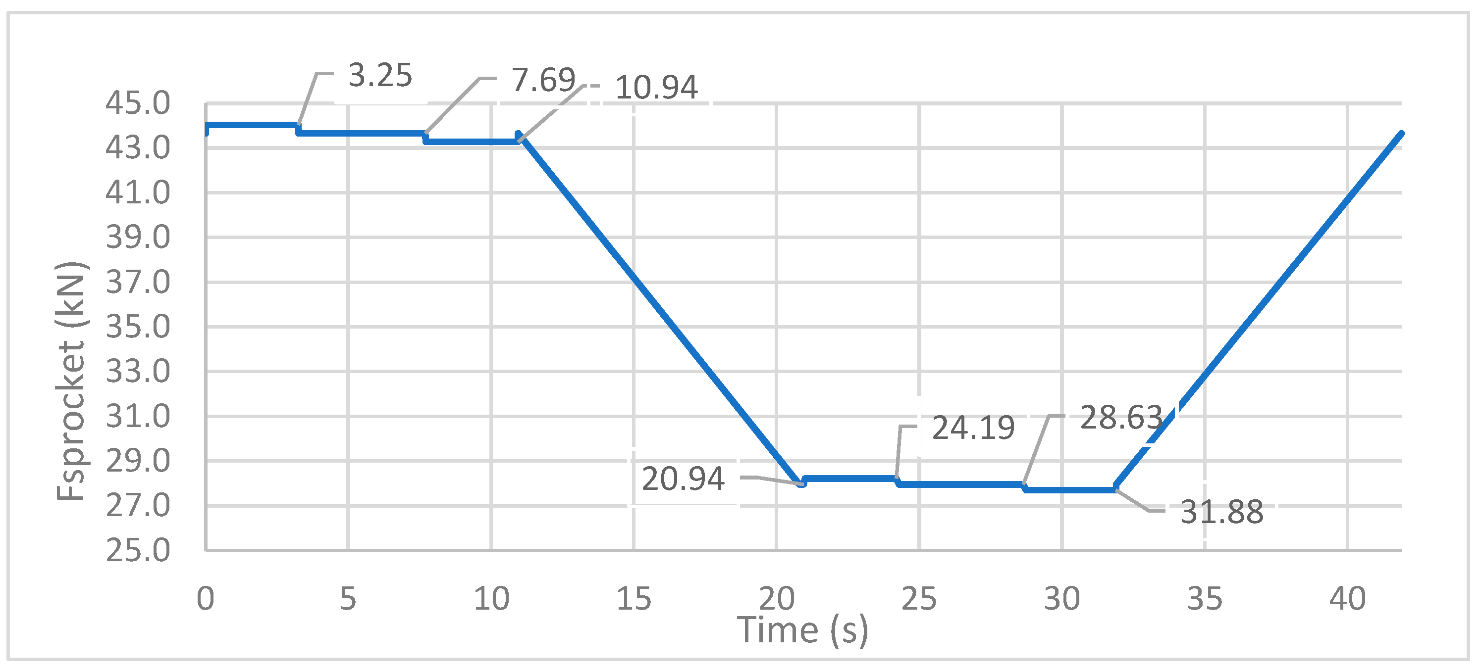
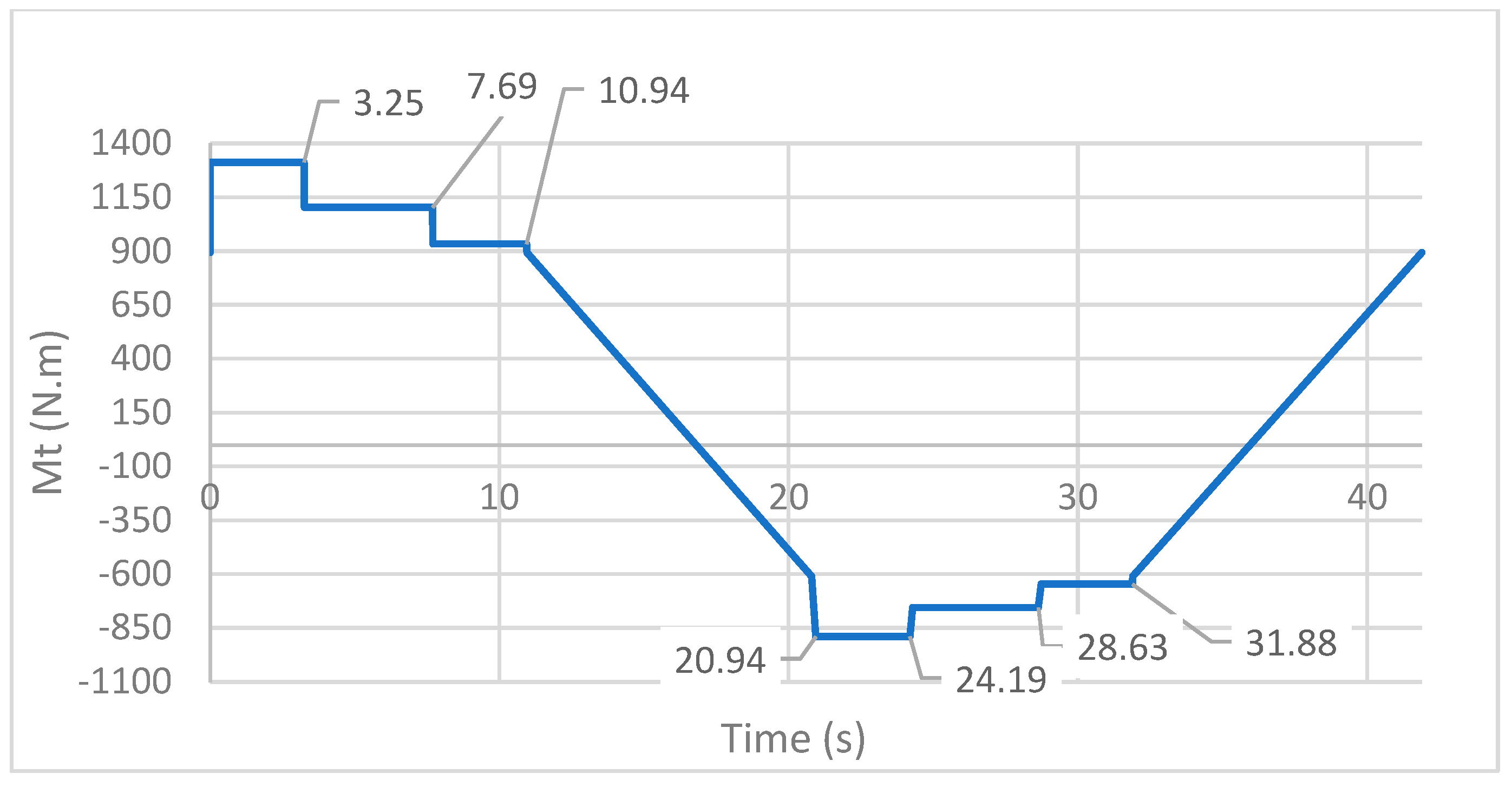
Figure 5,
Figure 6 and
Figure 7 present the evolution of these loads along the VTD operating cycle. For conciseness, the calculations behind
Figure 5,
Figure 6 and
Figure 7, based on [
15,
16], are not fully presented. Nevertheless,
Section 5 includes the calculation of the maximum loads per operating cycle (i.e., the maximum values of the diagrams).
The maximum vertical load on the sprocket, the maximum torsion moment and the maximum bending moment all occur when the hoisting carriage is accelerating upwards with its full maximum load. However, this only occurs between 0 and 3.25 s, i.e., in a small fraction of the machine’s operating cycle, which takes nearly 41.9 s.
The total time with a full load on the hoisting carriage is about 50% of the overall working time. In the other 50%, the hoisting carriage is moving down without the unit load.
Shafts subjected to stresses below the yield strength but above the fatigue limit (also known as endurance strength) will most likely fail from fatigue. The fatigue limit is the operating stress at which the specimens do not fail after at least 106 cycles. Excluding consideration of giga-cycle fatigue, which is not relevant for this application, stresses below the fatigue limit lead to infinite life.
Milela [
8] or Lee et al. [
9] give overviews of a variety of fatigue topics; within that vast domain, this work concentrates on stress-based fatigue analysis and design for high-cycle fatigue (HCF), adopting the classical approach commonly used in industry. References such as [
17,
18] introduce classical fatigue design for HCF with a focus on machine elements.
It is crucial to understand which load values should be considered in the calculation methods described in
Section 6,
Section 7 and
Section 8, and what the safety factors should be.
Section 6 concerns the use of Niemann’s approach [
19,
20],
Section 7 concerns the use of the ANSI/ASME B106.1M:1985 standard [
21], and a classical fatigue approach is used in
Section 8. The methods considered give some guidance on these subjects but do not define them entirely.
Niemann, [
19,
20], introduces the safety factor
, and the overload factor
. To establish
, it is necessary to consider the consequences of overloads, e.g., danger of death, long interruptions of the operation and production line or ease of repair or replacement of the damaged shaft. The overload factor
is defined as:
where
is the maximum load that occurs periodically in the machine cycle, and
is the nominal load.
The ANSI/ASME B106.1M:1985 standard [
21] does not directly define the values for the safety factor (SF). Nevertheless, it states that SF should be considerably higher than 1 if there are great uncertainties and the consequences of failure are serious, namely, in terms of safety and production stopping time. The same standard also introduces the duty cycle factor
and states that a shaft usually withstands variable amplitude loadings in service. Thus, the shaft design must consider start and stop cycles, transient overloads, vibrations and shocks, since these transients can have a significant impact on fatigue life. Usually, the values for the constant amplitude loads are known with sufficient accuracy, but the data for transient loads are not so well defined. Nevertheless, in the present case study, it was possible to determine the transient loads that occur in the acceleration and deceleration phases of the VTD operating cycle. The ANSI/ASME B106.1M:1985 standard [
21] states that it is not advisable to design a rotating shaft for finite fatigue life, as it will be confirmed in the following paragraphs.
An emergency stop will cause an overload on the hoisting shaft, and such events will certainly occur during the VTD service life. It is not possible to foresee how many times an emergency stop event will occur, but it will not be a very rare event. More unusual is the event of a free-fall with actuation of the safety gear. Overloads originated by the transfer of a load greater than the nominal maximum may also occur, but in this case, the hoisting carriage’s vertical movement will not be initiated. The EN 619:2002 + A1:2010 [
14] states that the system incorporating the VTD should prevent this from happening, for example, by assembling load cells on the conveyors that feed the VTD.
After analysing the inputs from these methods, some important decisions need to be made. If the nominal static load on the shaft is considered, an overload factor
> 1 should be selected. Another option is to use the dynamic load (including the VTD acceleration), and the overload factor
C is taken as 1. Recall that according to Niemann [
19], Equation (1),
is a load that repeats periodically.
It was decided to use the loads that occur during the initial 3.25 s of the operating cycle, where the hoisting carriage is accelerating upwards, in all the fatigue calculation methods. It is important to maintain the consistency of the previous decision with the safety factors and coefficients that will be used in each of the formulations, to avoid over-design. As explained previously, within the operating cycle, the VTD is half of the time with load and half of the time without load, which has a beneficial effect on fatigue life.
In [
2], Childs suggests the following safety factors for shaft design:
“1.25 to 1.5 for reliable materials under controlled conditions subjected to loads and stresses known with certainty,
1.5 to 2.0 for well-known materials under reasonably constant environmental conditions subjected to known loads and stresses,
2.0 to 2.5 for average materials subjected to known loads and stresses,
2.5 to 3.0 for less well-known materials under average conditions of load, stress, and environment,
3.0 to 4.0 for untried materials under average conditions of load, stress, and environment, and
3.0 to 4.0 for well-known materials under uncertain conditions of load, stress, and environment”.
The material used for the shaft under study is well known and reliable, and the environmental conditions are controlled and constant. The normal operation loads and the emergency stop loads are known, however, the number of occurrences of an emergency stop is unclear. As mentioned previously, the present work will size the shaft for the maximum loads within the equipment operating cycle, which only occur during 3.25 s of the overall cycle time. This is a defensive approach; therefore, a small safety factor within the range was used—1.5. Another option might have been to consider the weighted average between the maximum loads that occur during the 50% of the time that the hoisting carriage is going upwards with maximum load and the 50% of the time that the hoisting carriage is moving downwards without load. If the last approach had been used, the safety factor would have been increased to 2.
The decision was to consider the loads occurring in the upward acceleration phase; therefore,
, according to Niemann [
19,
20]. The safety factor was defined to be
, instead of using higher safety factors, since the hoisting carriage is under load only half of the operating cycle time.
Likewise, in the ANSI/ASME B106.1M:1985 standard [
21] method, the safety factor was defined as
, and the duty cycle factor was chosen to be
.
The stress originated by the loads acting on the hoisting shaft must be classified. It is intuitive that the bending moment due to the radial load on the sprocket will cause an alternating stress on the rotating shaft. It is less intuitive how the torsional moment should be categorized. Niemann [
20] defines a steady, an oscillating and an alternating stress. Notice that the direction of rotation of the hoisting shaft only reverses two times in each VTD operation cycle. Therefore, it would seem too defensive to consider the torsion as an alternating stress. At first sight, it would seem nearly steady. However, as discussed in the following paragraphs, the torsional load will cause an alternating stress that should be taken into account for infinite life calculation.
Another question that may arise is whether the infinite fatigue life design, corresponding to more than 106 cycles, is necessary. Would it be acceptable to calculate the shaft for a finite life, which would result in a smaller shaft diameter?
A shaft replacement is a complicated operation that may cause long production line downtime. Thus, it may be reasonable to require that the shaft not need to be replaced within the machine’s lifespan. In this case study, 10 years were considered based on the assessment of the number of load cycles. In each complete rotation of the shaft, the hoisting carriage moves 0.67 m up. Since the VTD hoisting stroke is 10 m, the shaft will complete almost 15 rotations in the upward movement plus 15 complete rotations in the downward movement. In each 180 degrees of shaft rotation, there is one alternating bending cycle. So, 30 complete shaft rotations will correspond to 60 bending cycles. The throughput of the VTD is 85 pallets per hour, so the shaft will suffer 5134 bending cycles per hour. Since the VTDs will be operating in an automatic system that works 24 h a day, the shaft will withstand 123,186 bending cycles/day, 30,796,594 per year, and 308 × 10
6 cycles in 10 years. Thus, it is mandatory to calculate the shaft for infinite life. In the previous calculation, 250 working days per year were considered, according to DIN 15020:1974 [
22].
Regarding the torsion stress, and applying the same rational, there will be 85 alternating torsional stress cycles per hour (two per machine up and down cycle), 4122 in each day, 1,030,585 per year and around 10 × 10
6 cycles in 10 years, much lower than the number of alternating stresses due to the rotational bending but still larger than the 10
6 cycles, which justify an infinite life calculation.
Figure 8 shows schematically the relationship between both stresses. The graphic was simplified to allow better visualization, since 30 periods of the alternating bending stress curve would occur before the inversion of the signal of the alternating torsional load stress.
4. Shaft Diameter Calculation—Peak Loads
After the thorough analysis of the system and the definition of the input values for calculations, a first analysis concerns shaft behaviour under peak loads. The input data are found in
Table 1 and
Table 2, including the parameters description. The notation for this and subsequent sections is given in Nomenclature part. The ANSI/ASME B106.1M:1985 standard [
21] notes that there is not a comprehensive method to determine the impact of the peak load on the shaft fatigue life. Miner’s law could be used if the occurrence of peaks could be quantified, but in the present case, the number of occurrences is unpredictable, precluding their explicit consideration in fatigue calculation.
The peak load to be considered results from the emergency stop by the gearmotor brake, which results in a torsional moment
= 1929 N·m, and an acceleration of
= −4.829 m/s
2. The previous values were obtained using the software [
16]; refer to
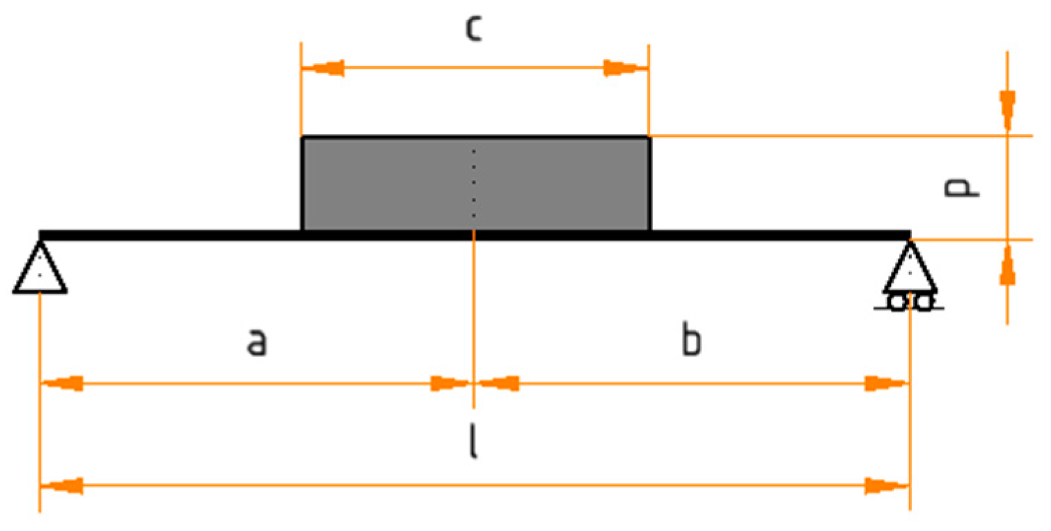
Table 2. The radial load
, acting on the hoisting shaft on an emergency gearmotor brake, is calculated as
Figure 9 presents a model and the notation used. Recall that the failed shaft diameter was
di = 50 mm.
In the shaft critical section and under the peak load, the bending moment and stress, the shear stress due to the load and to the torque, are calculated as:
From Equation (4),
= 2092 N·m; from (5),
; and from Equation (6),
.
From Equation (7), ; from Equation (8), . Replacing , in Equation (10), N, in the critical middle section of the keyseat area; thus, MPa, from Equation (9). The total shear stresses will be .
To conclude this static strength analysis, the von Mises criterion was used:
For steel 34CrNiMo6, refer to
Table 3, and considering
, Equation (11) gives
, confirming that the shaft can withstand the peak load, and implying that its failure is likely due to fatigue. Unfortunately, the broken pieces were not available, so no scanning electron microscopy could be used to possibly identify striations. The work proceeded with a fatigue analysis using several methodologies.
6. Calculation of the Shaft Diameter According to the Niemann Method
After defining the load values to be used as input for all the shaft diameter calculation methods (refer to
Section 5), the first calculation was done according to Niemann [
19] (see Table 17.2 of that reference). For a torsional load
= 1323 N·m, it defines a shaft diameter of around 80 mm, whereas before the present redesign, the diameter was only 50 mm. Even if the reference used (Table 17.2 of [
19]) considers a lower strength steel, as will be seen later, this first calculation showed that the shaft design required attention.
Still in [
19], a more detailed calculation method may be found (Table 17.5 of that reference). For a shaft under torsional and bending loads, Equations (21) and (22) are introduced.
For a solid shaft,
,
= 1 for oscillating torsion with alternate bending, and
for alternating torsion and bending. As shown in
Section 3, and contrary to how it may seem at first sight, the torsional load is also to be considered alternating.
The Niemann method defines a
= 500 kgf/cm
2 (~50 MPa), for ST50.11 steel on a hoisting shaft application. The mechanical properties of the ST50 steel could be considered equivalent to the current steel S355 Jr of NP EN 10025 + A1:1994 [
23]. Currently, higher strength steels are used in this type of application.
Table 3 compares the mechanical properties of the S355 Jr steel (NP EN 10025 + A1:1994, [
23]) with the 34CrNiMo6 steel (EN 10083:2006 [
24]).
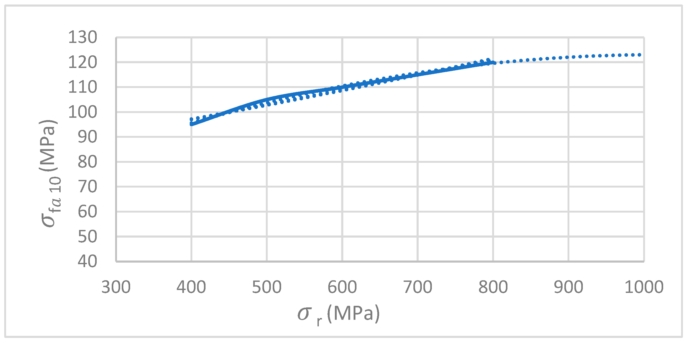
On first thought, the fatigue strength—
—in a keyway torque transmission area of a 34CrNiMo6 shaft might be expected to be approximately twice that of a ST50 one. However, as shown in Niemann [
20], the use of high strength steels does not improve so much the allowable fatigue stress for a shaft under alternating bending in a keyway area—
. In [
20] (Figure 3.27 of that ref.),
is 105 MPa for the ST50 steel, and increases to around 120 MPa for a steel with
= 800 MPa, the highest value considered. Extrapolating, see the blue dotted line in
Figure 10,
= 1000 MPa corresponds to
125 MPa. Notice that
is the allowable fatigue strength in keyway under alternating bending for one test specimen with a diameter of 10 mm and a material with a given
.
To calculate the allowable fatigue strength in the critical area of the shaft, the keyway area, it is necessary to consider other factors according to:
Considering the shaft diameter of 50 mm, the size factor is
0.7; refer to
Table 4. According to
Section 3, the safety factor
is 1.5, and the overload factor
. From (23),
= 58 MPa in the keyseat area.
The results from the calculation with Equations (21) and (22) are summarized in
Table 5. The first iteration resulted in a shaft diameter of 73 mm, so the
value was corrected to 0.65 in the second iteration. According to [
20], for oscillating torsion with alternate bending, the diameter of the shaft in the keyway area would need to be 72.5 mm considering
= 1, and 74.8 considering
= 1.7 for alternating torsion and bending. Recall that before the redesign, the shaft diameter was 50 mm only, so it looked unsatisfactory. Even considering
,
and
= 1, the required shaft diameter would need to be higher than 50 mm, around 63 mm.
As already explained, the input values in the previous calculation were and = 1323 N·m.
7. Calculation of the Shaft Diameter According to ANSI/ASME Methodology
Given the losses incurred with the failure, and since the redesigned shaft is intended for use in several future machines, it was decided, for comparison purposes, to use yet another procedure to redesign the shaft for infinite life, following the ANSI/ASME B106.1M:1985 standard, [
21]. Although now withdrawn, this standard is a commonly used guide for shaft design, as stated, e.g., by Childs, [
2,
3], and it continues to be included in ANSI/CEMA B105.1-2015, [
25]. The notation from the standard [
21] is used here.
According to [
21], for steels with ultimate tensile strengths lower than 1400 MPa, such as the 34CrNiMo6 steel, in the absence of detailed testing, the approximation
, where
is the fatigue limit of polished unnotched test specimen in reversed bending, and
is the ultimate tensile strength of the steel, should provide reasonable accuracy.
According to ANSI/ASME B106.1M:1985, [
21], the shaft diameter is calculated using Equation (24) based upon the von Mises criterion,
where
is the shaft diameter (m),
is the factor of safety and
is the corrected endurance (fatigue) limit of the shaft in reversed bending, calculated using Equation (25),
is the tensile yield strength (N/m
2) of the steel,
is the static mean torque (N·m) and
is the reverse bending moment (N·m). Using Tresca instead of von Mises, this classical result is found, e.g., in [
26] (chapter 13).
The following Equation (25) from [
21] is also presented in many publications. Given its important role in the present analysis, its use is presented in some detail in the following paragraphs.
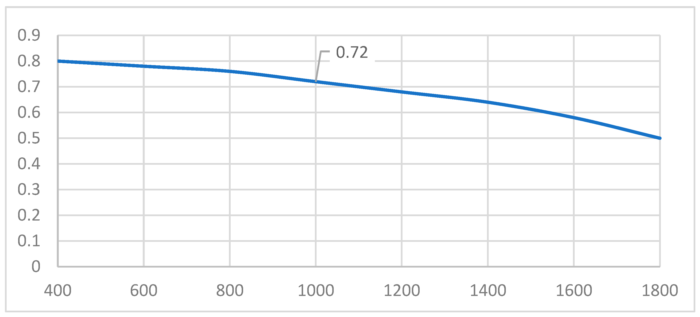
The first correction factor in Equation (25) is the surface finish factor . This factor accounts for the difference in the surface condition between the shaft under evaluation and one highly polished test specimen. As recalled in the ANSI/ASME standard, experiments have shown that the surface condition can have an important effect on the fatigue strength, since fatigue cracks are usually initiated at the surface of the shaft, where stresses are higher. For reference, the machined surface category is to be considered for shafts with surface roughness ranging from Ra 1.6 to Ra 6.3 µm.
According to [
21], for the shaft under evaluation with Ra 3.2 µm, manufactured in 34CrNiMo6, with ultimate tensile strength
= 1000 MPa,
0.72,
Figure 11.
The size factor
quantifies the decrease of the fatigue limit with the increase of the diameter, as briefly discussed in [
21], where different equations for
depending on the diameter range, are presented. For shafts with a diameter larger than 50 mm and lower than 254 mm, Equation (26) is to be used; thus, for the case study diameter of 50 mm,
.
According to [
21], the reliability factor
should be taken in account, due to the variability of the mechanical properties of the specimen. In a safety risk assessment analysis, the VTD hoisting shaft would be considered critical, as its rupture would allow the hoisting carriage to free fall. The factor
reduces the fatigue limit, so that a smaller percentage of the population fails during the machine’s life, increasing reliability. In this calculation, a reliability rate of 90% was chosen, so
= 0.897; refer to
Table 6.
The temperature factor , translates the effect of the temperature on the fatigue limit. There is a trend to use VTDs in cold temperatures, down to −30 °C in deep freeze warehouses, so this factor appeared to be relevant. The ANSI/ASME standard states that for operating temperatures from −57° to 204°, the fatigue limit is not affected by temperature for most steels, so .
The duty cycle factor—
—was already discussed in
Section 3. The value
will be considered for this calculation (refer to
Section 3 for more details).
The miscellaneous effects factor——concerns different factors that may affect the fatigue life (e.g., residual stresses from the manufacturing process, corrosion, surface coating). Its value was taken as , addressing this uncertainty with the safety factor.
Failure usually occurs in a notch, keyway, shoulder or other discontinuity where the stresses are amplified. The fatigue stress concentration factor—
—represents the effect of the stress concentration on the fatigue limit of the shaft, according to Equation (27).
where
is the fatigue strength reduction factor and is calculated according to Equation (28). Equations (27) and (28) are used by the ANSI/ASME B106.1M:1985 standard [
21], found in many references that address the fatigue damage mechanism, such as [
11,
18], for instance.
where
is the notch sensitivity of a given material. The notch sensitivity can be used to relate the fatigue strength reduction factor—
—to the theoretical stress concentration factor
. It is interesting to know that experience has shown that low-strength steels are less sensitive to fatigue at notches than the high-strength steels. For more details, refer to [
18] (Section 1.9). Ref. [
21] gives directly the value for
for a profiled keyway under bending stress in solid round steel shafts, according to
Table 7, without the need to determine the notch sensitivity factor
, nor the theoretical stress concentration factor
.
The shaft material—steel 34CrNiMo6, EN 10083-3:2006 [
24], has a Brinell hardness number—BHN [
27]—higher than 200, so
.
By entering all the values for the factors in Equation (25), = 142 MPa. From Equation (24), considering FS = 1.5, the minimum shaft diameter would be 59.3 mm. This shows that the 50 mm diameter is not enough to ensure the fatigue strength of the shaft.
As already explained, the input values in the previous calculation were , and = 1323 N·m.
The ANSI/ASME standard considers reversed bending and steady or nearly steady torsion. However, as seen in
Section 3, in the present case, the torsion is also alternating, albeit with a lower frequency. Although the number of reversed torsion cycles is much lower than the number of reversed bending cycles, it will surpass 10
6 cycles and should be considered in the shaft design. These circumstances led to a final fatigue calculation that could fully accommodate the service conditions of the shaft, as presented in the next section (
Section 8).
8. Calculation of the Shaft Diameter Taking into Account the Alternating Torsion
The ANSI/ASME B106.1M:1985 standard [
21] is based on classical fatigue design considerations. It represents a particular situation of a more general treatment presented, e.g., in [
26], or in [
4,
5,
28], and other references mentioned in
Section 1. In the following, the notation of [
17] is adopted.
Refs. [
17,
21] define the fatigue limit strength—
—as
, where
is the ultimate tensile strength, and it is necessary to affect the fatigue limit strength with the correction factors.
Table 8 defines the load type factor
.
The gradient factor, also known as size factor
, is equivalent to the ANSI/ASME method factor
and is shown in
Table 9.
The surface finish factor
, is equivalent to the ANSI/ASME method factor
. According to [
17],
, the same as
. The temperature factor is
= 1 for the case study appliance environmental temperatures.
Similar to the ANSI/ASME method, the reference [
17] introduces the reliability factor
, with the same values shown on
Table 6 of
Section 7. Thus,
= 0.897.
So, the limit fatigue strength will be corrected by these factors according to Equation (29) for the rotating bending stress, and (30) for the alternate torsional load.
resulting in
for the rotational bending load, and
for the reversed torsional load.
As in the ANSI/ASME method, ref. [
17] gives directly
for profiled keyways, according to
Table 10.
As explained in
Section 7, BHN is larger than 200, so
and
.
In the previous table, it is possible to notice the fundamental tendency for the harder and stronger materials to be more notch-sensitive. This means that changing from a soft to a harder and stronger steel normally increases part fatigue strength, but the increase is not as great as might be expected because of the increased notch sensitivity. As can be seen in
Table 10, the harder material with 200 BHN has a stress concentration factor—
—greater than the softer material.
There are different types of loads acting on the keyway area—bending and shear stress due to the radial load on the sprocket, torsional load due to the gearmotor output torque. Equivalent stresses
were calculated as
where
and
are the mean stresses. The bending stress has zero mean stress,
(or
R = σmin/σmax = −1). The alternate bending stress—
—results from the bending moment calculated in
Section 5—
, and the shear stress—
—results from the alternating torsional load calculated in
Section 5 = 1323 N·m.
Considering a shaft diameter of 50 mm, as in the design before the redesign, using Equations (5) and (6), , and .
From Equation (33),
, and from (31),
for the bending stress. For the torsional and shear stresses, from (35),
. As seen in
Section 4,
N in the middle section of the shaft—
—that is the critical section for fatigue calculation. From (34),
, and (35),
MPa.
The final validation was done by applying the Tresca criterion according to Equation (36). In the context of classical fatigue design, the use of Tresca criterion is found, e.g., in [
11].
where
is the safety factor.
For a shaft diameter of 50 mm, we have from Equation (36), 554 MPa, higher than the allowed 400 MPa, for = 1; thus, far from ensuring infinite fatigue life!
It would be necessary to increase the shaft diameter to 63.9 mm to ensure infinite fatigue life, taking into account the alternating rotational bending load and alternating torsional load, with a safety factor of 1.5. Recall that this value is higher than the 59.3 mm that resulted from the ANSI/ASME method,
Section 7, that did not take alternate torsion into account.
9. Conclusions
A redesign of a failed 50 mm diameter hoisting shaft was presented. The importance of making a thorough assessment of the VTD operation before the shaft redesign was emphasized, making it possible to realize that the torsional load from the gearmotor output torque should be considered alternating and taken into account as such in the fatigue redesign performed.
The peak load 218 MPa was seemingly low when compared with the fatigue limit MPa (34CrNiMo6 steel). This might lead to the misleading consideration that the calculation of the shaft for fatigue was unnecessary, but that would be an expensive mistake.
In fact, the keyseat area is subjected to high stress concentration, with a serious impact on the maximum fatigue allowable stress. All the methods described in the present work indicate that the fatigue limit allowable stress in keyseat areas does not increase proportionally with the ultimate strength of the steel. This means that changing from a soft to a harder and stronger steel normally increases the part fatigue strength, but the increase is not as great as might be expected.
For the shaft material, according to a rough sizing presented by Niemann, the maximum allowable stress for infinite fatigue life in the keyseat area was 58 MPa, whereas it was 142 MPa according to ANSI/ASME, illustrating the conservativeness of the Niemann method.
The ANSI/ASME method was developed for steady torsional loads. To consider reversed torsional loading and ensure infinite fatigue life under reversed torsion and rotational bending, a classical fatigue model combining shear and torsional stresses with bending and normal stresses using equivalent stresses was performed.
Overloads, including possible misuses of the VTD, are difficult to quantify. According to ANSI/ASME and to Niemann, these transient loads need to be considered through the incorporation of safety factors that take into account the severity of a hoisting shaft rupture in terms of safety, machine damage and machine downtime.
The redesigned shaft diameter was, according to Niemann, d = 74.8 mm; according to the ANSI/ASME method, it was d = 59.3 mm; and according to the classical fatigue model, it would be d = 63.9 mm. Taking into account the transient overloads, finally, d = 70 mm was adopted for the redesigned shaft.


