Article

Geomechanical Feasibility Analysis of Salt Cavern Gas Storage Construction in Sanshui Basin, Guangdong Province

1
PetroChina Research Institute of Petroleum Exploration & Development, Beijing 100083, China
2
College of Petroleum Engineering, China University of Petroleum, Beijing 102249, China
*
Author to whom correspondence should be addressed.
Eng 2022, 3(4), 709-731; https://doi.org/10.3390/eng3040048
Submission received: 23 November 2022 / Revised: 14 December 2022 / Accepted: 15 December 2022 / Published: 16 December 2022
(This article belongs to the Special Issue GeoEnergy Science and Engineering)

Abstract

:
Salt cavern gas storage has become the key project of current and future underground gas storage (UGS) facilities construction due to their efficient peak-shaving and supply assurance capacities. The Sanshui Basin in Guangdong Province, China, is rich in salt resources and has high-purity salt rock, which is a potential area for the construction of salt cavern underground gas storage. To speed up the large-scale construction of underground gas storage in China and promote the sustainable development of the natural gas market, it is very necessary to analyze the geomechanics of the target salt layer and study the feasibility of gas storage construction. Based on comprehensive experiments of rock mechanics and thermodynamics, the strength, creep and temperature-sensitive mechanical properties of the target rock in Sanshui Basin were studied. Then, according to the geological conditions of Sanshui salt formation, a three-dimensional geological model was established to analyze the stability of salt cavern gas storage under the injection-production operation. The results show that the average tensile strength and uniaxial compressive strength of salt rock are 1.51 MPa and 26.04 MPa, respectively, showing lower strength. However, under triaxial compression, the compressive strength of salt rock increases significantly, and there is no obvious shear failure phenomenon observed. Moreover, after the peak strength, the salt rock still has a large bearing capacity. In addition, under the confining pressure of 30 MPa, the strength of salt rock decreases by 8.3% at a temperature of 60 °C compared with that at room temperature, indicating that the temperature has a low, modest effect on the mechanical properties of salt rock. The stability analysis shows that, under an injection-production operating pressure of 10–23 MPa, the displacement, plastic zone range and volume convergence rate of single cavity and cavity group are small, and the cavity shows good stability. Overall, the target salt formation in Sanshui Basin, Guangdong Province, presents a good geomechanical condition suitable for the construction of underground salt cavern gas storage. This study can provide a reference for the development and design of salt cavern UGS.

1. Introduction

Salt rock is recognized as a good medium for underground energy storage [1,2]. The unique properties of salt rock were discovered abroad early, and is utilized for the storage of oil, gas and various industrial wastes. In the early 1940s, Canada first used salt caverns to store liquefied petroleum gas. In the 1950s, North America and Europe began to use salt cavities to store light hydrocarbons. After the 1960s, the use of salt caverns for compressed air energy storage and hydrogen energy storage has been developed in the United States, Germany and other countries [3,4]. In 1978, Germany took the lead in building the first commercial salt cavern compressed air energy storage (CAES) power station (Huntorf) in the world, with a transmission power of 321 MW. The second commercial salt cavern CAES power station (Mclntosh in Alabama) was constructed in the United States in 1991, forming a 110 MW transmission power scale [5]. With continuous exploration and practice, there are more and more types of salt cavern storage, which are also used to store hydrogen, helium, etc. An example is the Helenburg salt cavern helium storage in Russia [6]. Among many storage media, natural gas is the energy medium with the largest storage capacity in salt cavern storage [7]. Up to now, more than 108 underground salt cavern gas storages have been built and operated in the world, including more than sixty in Europe, forty-seven in North America and one in China, most of which exist in the United States and Germany [8]. During more than 60 years of development of salt cavern gas storage in salt dome formation, mature theories and technologies have been formed abroad in terms of water solution cavity construction, large wellbore cavity building, stability evaluation and injection-production operation [9,10].
China’s rich salt mineral resources are distributed throughout 15 provinces. Making full use of salt mineral resources to build underground gas storage will greatly promote the sustainable development of China’s natural gas market, which is also one of the key contents of China’s “Fourteenth Five Year Plan” [11] on energy development planning. With the successful development and utilization of Jintan Salt Mine’s salt cavern gas storage, in order to ensure the stable supply of natural gas in China’s market and relieve the pressure of transportation and storage brought by the rapid growth of gas demand, China is stepping up efforts to develop existing salt mineral resources around the main cities, accelerating the construction of salt cavern gas storage, and forming a series of infrastructure supporting the supply and marketing of natural gas in large- and medium-sized cities. At present, Hubei Yunying Salt Mine, Jiangsu Huai’an Salt Mine, Henan Pingdingshan Salt Mine and other salt cavern gas storage areas have been built or are planned to be built, and the feasibility studies of gas storage construction, such as site selection and rock mechanical properties, have been carried out successively. In the geomechanical analysis of the construction of salt cavern gas storage, the mechanical parameters of the target salt layer are the key and foundation for the construction of gas storage [12,13,14,15]. Scholars have carried out a lot of research on the mechanical properties of salt rock. Ma [16], Liu [17] and Alkan [18] et al. studied the yield characteristics and failure criteria of salt rock based on a large number of core uniaxial-triaxial and tensile tests. Yang [19], Li [20] and Mansouri [21] et al. carried out a large number of indoor creep tests and loading and unloading tests to study the creep characteristics of salt rock and its deformation characteristics. Wanyan [22] et al. carried out triaxial compression creep tests on salt rocks from salt mines in Yunying, Hubei province, Huai’an, Jiangsu province and Pingdingshan, Henan province, and compared the creep characteristics of salt rocks in different regions. Liu [23], Jiang [24] and Wang [25] et al. studied the mechanical properties of layered salt rock and the influence of interlayer on the mechanical properties of salt rock. Gao [26] and Li [27] et al. studied the influence of temperature on the mechanical properties of salt rock by using core high temperature tests, and obtained the understanding that the mechanical properties of salt rock deteriorate due to temperature rise. At present, the research on mechanical properties of salt rock is mainly based on a combination of experiment and theoretical analysis, taking into account the influences of tensile and compressive strength, yield, creep and temperature on the characteristics of the rock. This provides the necessary basic data for the construction of gas storage cavity and the long-term stability of the cavity.
A salt mine in Sanshui Basin, Guangdong Province, is rich in salt rock resources with high purity and medium buring depth of 1200–1300 m. It is a potential mining area for building salt cavern UGS. At present, there is little research on the mechanical properties of rock in this mining area. In order to fully evaluate the feasibility of the construction of salt cavern gas storage in this area, it is necessary to carry out experimental research on the mechanical properties of salt rock in the main salt layer, recognize the deformation law and rheological properties of salt rock and evaluate the stability of salt cavern under operation pressure, so as to provide a theoretical basis for the construction of salt cavern gas storage in Sanshui Basin, Guangdong Province.

2. Experiment Analysis and Discussion

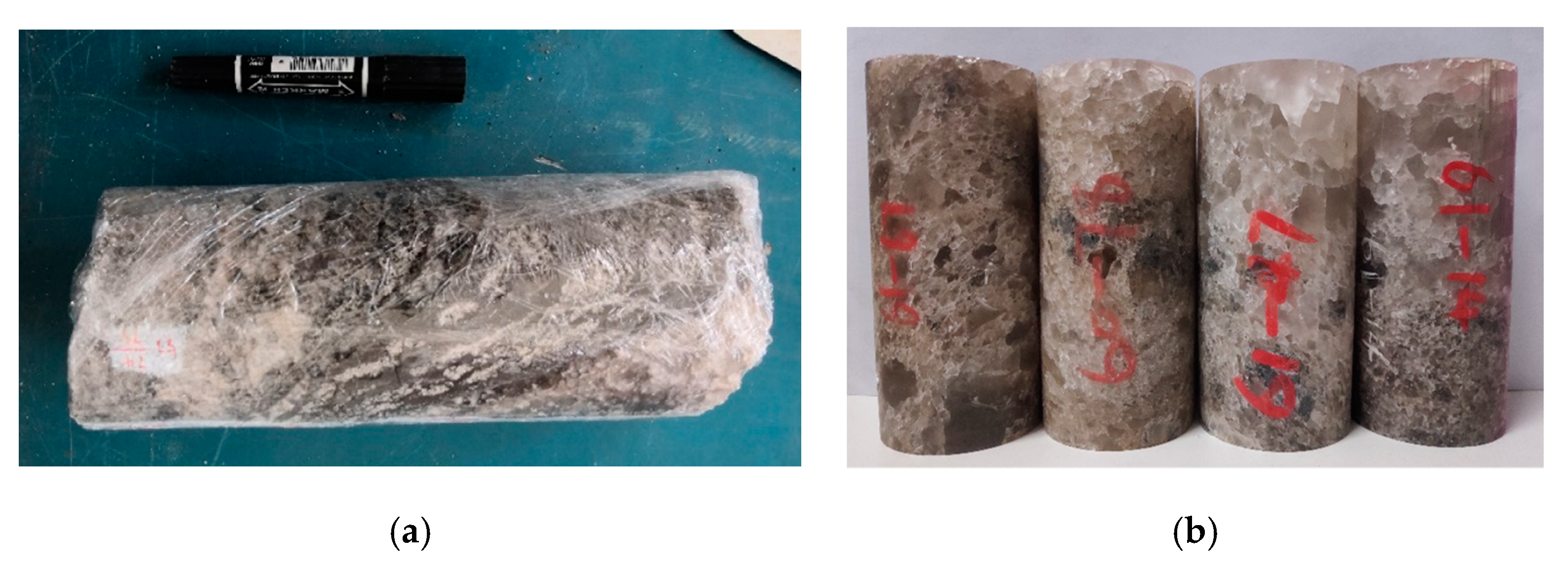
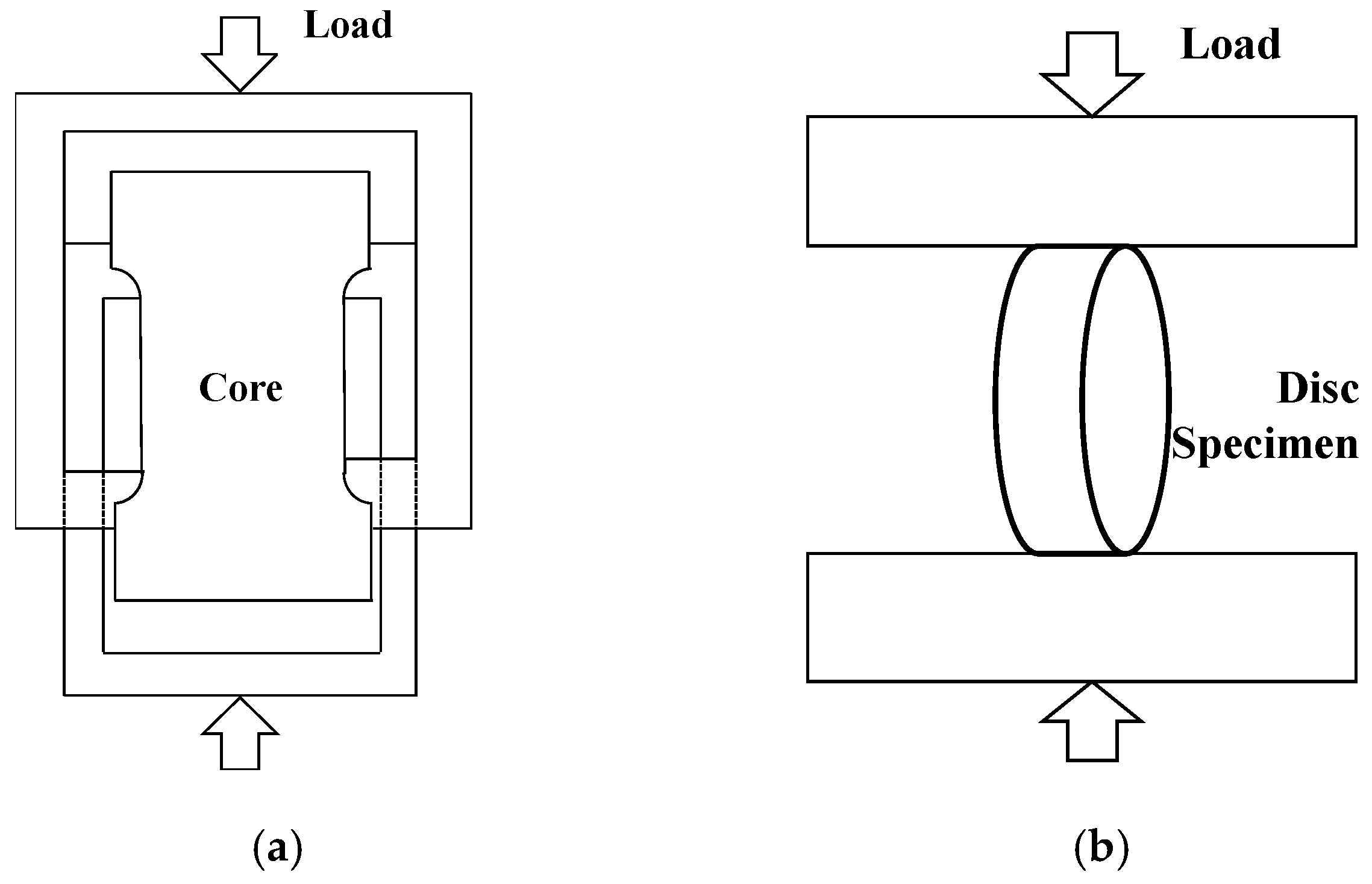
2.1. Experiment Method

The experimental salt rock core used in this study is taken from the main salt layer in Sanshui Basin, Guangdong Province, with a buried depth of about 1200 m. Some core columns collected by the coring barrel are shown in Figure 1a. A core from the core column was drilled and processed into standard rock sample for experiments (Ø50 ∗ H100 mm), as shown in Figure 1b. As the salt rock is easily dissolved in water, in order to avoid large damage to the core caused by the conventional coring method, the wire cutting process was adopted for this coring. During processing, the wire cutting fluid did not contain water or react with the core, which ensured the core is not damaged and polluted.
The experimental salt rock core was grayish black due to impurities, and some salt rock cores contained an obvious mudstone interlayer. This research mainly studies the mechanical behavior and deformation law of salt layer in the target area through direct tension, Brazilian splitting, uniaxial, triaxial and creep tests, as well as strength and creep tests at high temperatures. The self-designed direct tensile apparatus, high-temperature and high-pressure triaxial apparatus and servo-controlled testing machine of the Rock Mechanics Laboratory of China University of Petroleum (Beijing) were used to conduct the salt rock mechanics test. See Table 1 for basic physical parameters and the experimental scheme of salt rock core. From the perspective of physical parameters, the salt rock of the target salt bed in Sanshui Basin contains impurities, with a density range of 2.15–2.43 g/cm3 and a large distribution range, with an average density of 2.24 g/cm3. Acoustic data show that the longitudinal wave velocity is about twice that of the shear wave.

2.2. Analysis of Experimental Data

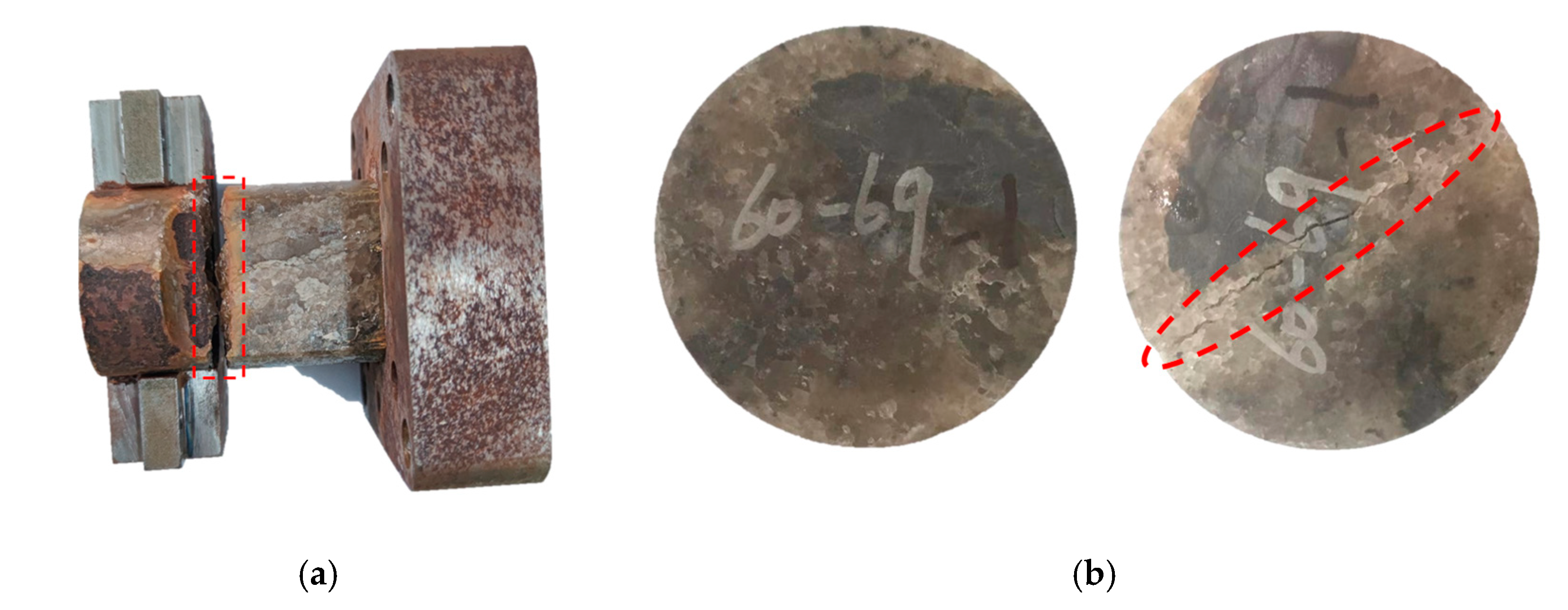
2.2.1. Tension Tests

The direct tensile test adopts the self-designed core direct tensile loading device, which can directly conduct the direct tensile test on the press, as shown in Figure 2a. All the cores were processed into an I-shape for the experiments. The Brazil splitting test method was used for indirect tension. The tensile properties and parameters of salt rock were determined by comparing the two methods. Figure 3 shows that, in the direct tension test, the salt rock fracture occurs at the neck (as shown in Figure 3a, the red dotted line), and the fracture surface is basically perpendicular to the axial direction. However, in the indirect tension test, the core is split into nearly symmetrical halves. The results of both experiments are shown in Table 2. The tensile test shows that there is little difference between the core strength measured by the two methods, indicating that both methods can be used as the core tensile strength measurement mode. The experimental results show that the tensile strength of salt rock in Sanshui Basin is not high, ranging from 1–2 MPa with an average of 1.51 MPa. For salt cavern gas storage, the tightness of the cavity is one of the key parameters for its safety assessment. In the process of construction and operation, it is necessary to control the pressure in the cavity to avoid tensile damage in key parts, which may lead to the risk of cavity instability or sealing failure.

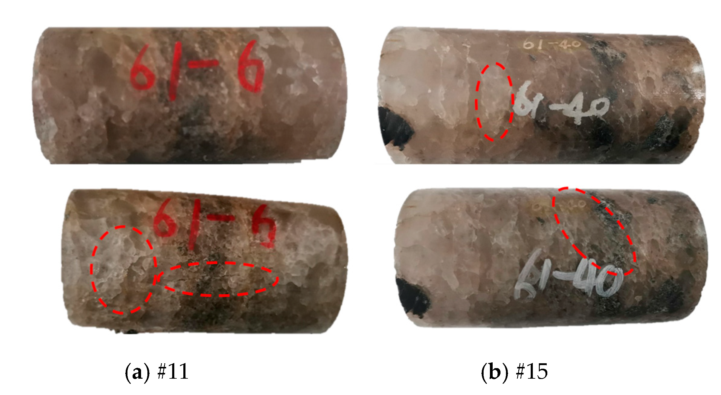
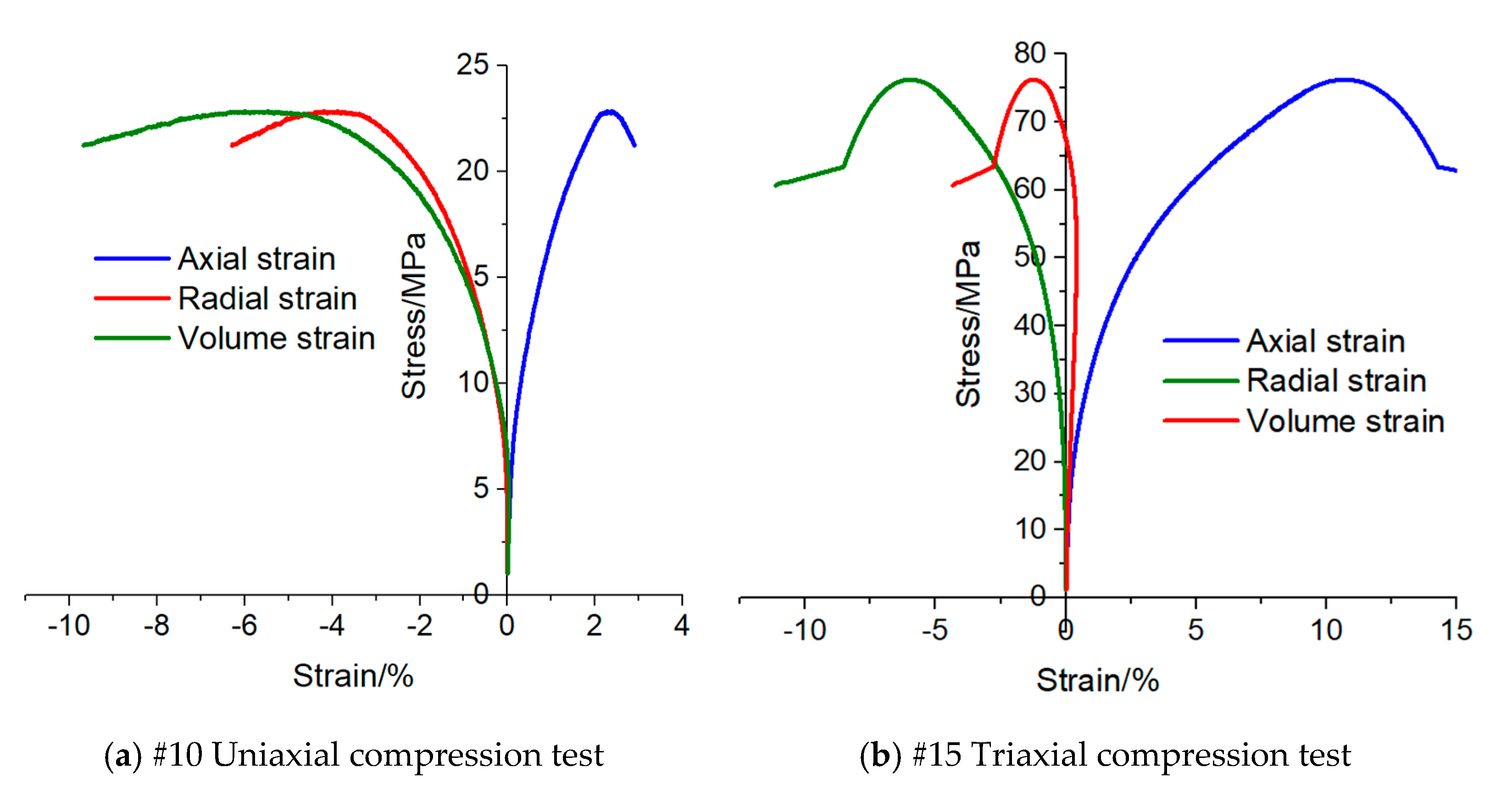
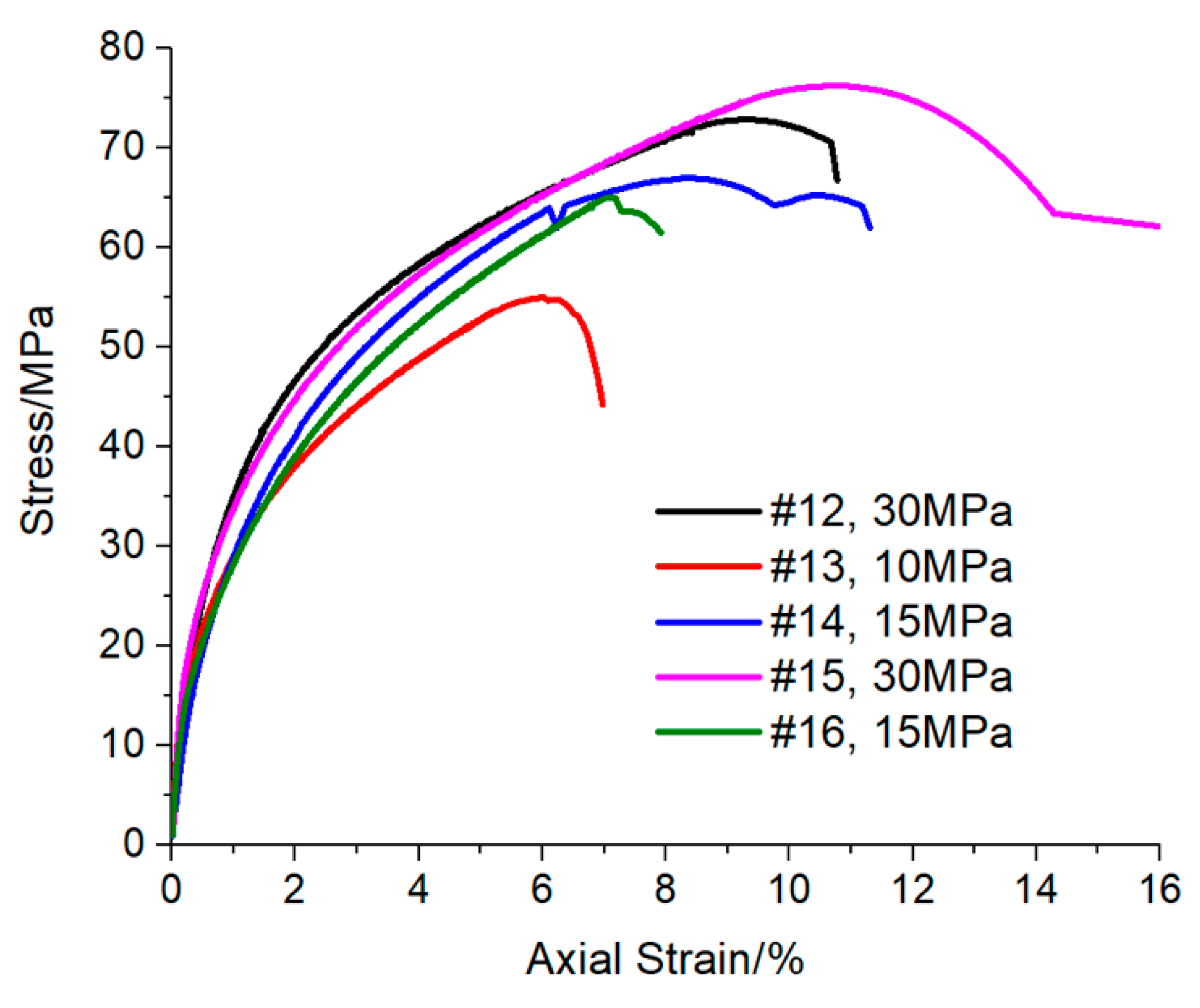
2.2.2. Uniaxial/Triaxial Test at Room Temperature

The core length used in the uniaxial and triaxial compression tests of salt rock in Sanshui Basin was about 100 mm. It can be seen from some core photos after the experiment that, under uniaxial compression, tensile cracks along the axial direction were produced in the salt rock (as shown in the red dotted line at the lower part of Figure 4a), while under triaxial compression, no obvious cracks or damage were produced in the salt rock samples, and the salt rock samples were in a radial expansion state. Core photos show that the crystal grains of salt in the salt rock fabric of Sanshui Basin are large (as shown in the red dotted line circle in Figure 4b above), visible to the naked eye, and the size is inlaid with an irregular distribution. There are also randomly distributed impurity grains of different sizes inside. The experimental results show that under the action of stress, there is dislocation, sliding and fragmentation between the salt rock crystal particles. Large salt rock crystal particles are broken into many small crystal particles, and the boundaries between the particles are denser and clear (as shown in the red dotted circle below Figure 4a,b). Uniaxial compression test results in Table 3 show that the average peak compressive strength of salt rock is 26.04 MPa, which is about 17.2 times of its uniaxial tensile strength, and the average elastic modulus and Poisson’s ratio are 6.16 GPa and 0.296, respectively. Under uniaxial compression, the stress–strain curve of the salt rock in the salt mine has obvious elastic–plastic behavior. The elastic stage is short. It then goes through a long plastic flow stage. Before the peak failure, the axial strain and radial strain both increase significantly, and the volumetric strain also shows that the dilatancy of salt rock core under uniaxial compression test is obvious.
Under the triaxial compression test, the peak strength of the rock generally increases with the increasing of confining pressure. Compared with the uniaxial compressive strength, the strength of the core under triaxial compression has been greatly improved, and the elastic modulus also significantly increased, as shown in Table 4. The stress–strain curves (Figure 5) show that the strain of salt rock increases significantly when it reaches failure under triaxial compression test. The axial strain of the core is larger than the radial strain under the confining pressure, indicating that the confining pressure has a greater impact on the radial deformation of the core salt rock. Volume strain shows that at the initial stage of the experiment, the core is mainly compacted, which is obvious from the triaxial compression experiment. Then, the damage occurs in the rock when microcracks are generated and expand, and volume expansion happens at the beginning of the experiment. The core compaction is significant, and under the influence of confining pressure, the volume expansion is significantly weakened compared with the uniaxial compression condition. In Figure 6, axial stress and strain under different confining pressures show that, with increasing of confining pressure, the peak strength of salt rock does not increase by the same factor, but rather increases slightly. After reaching peak strength, the salt rock still has a high bearing capacity.

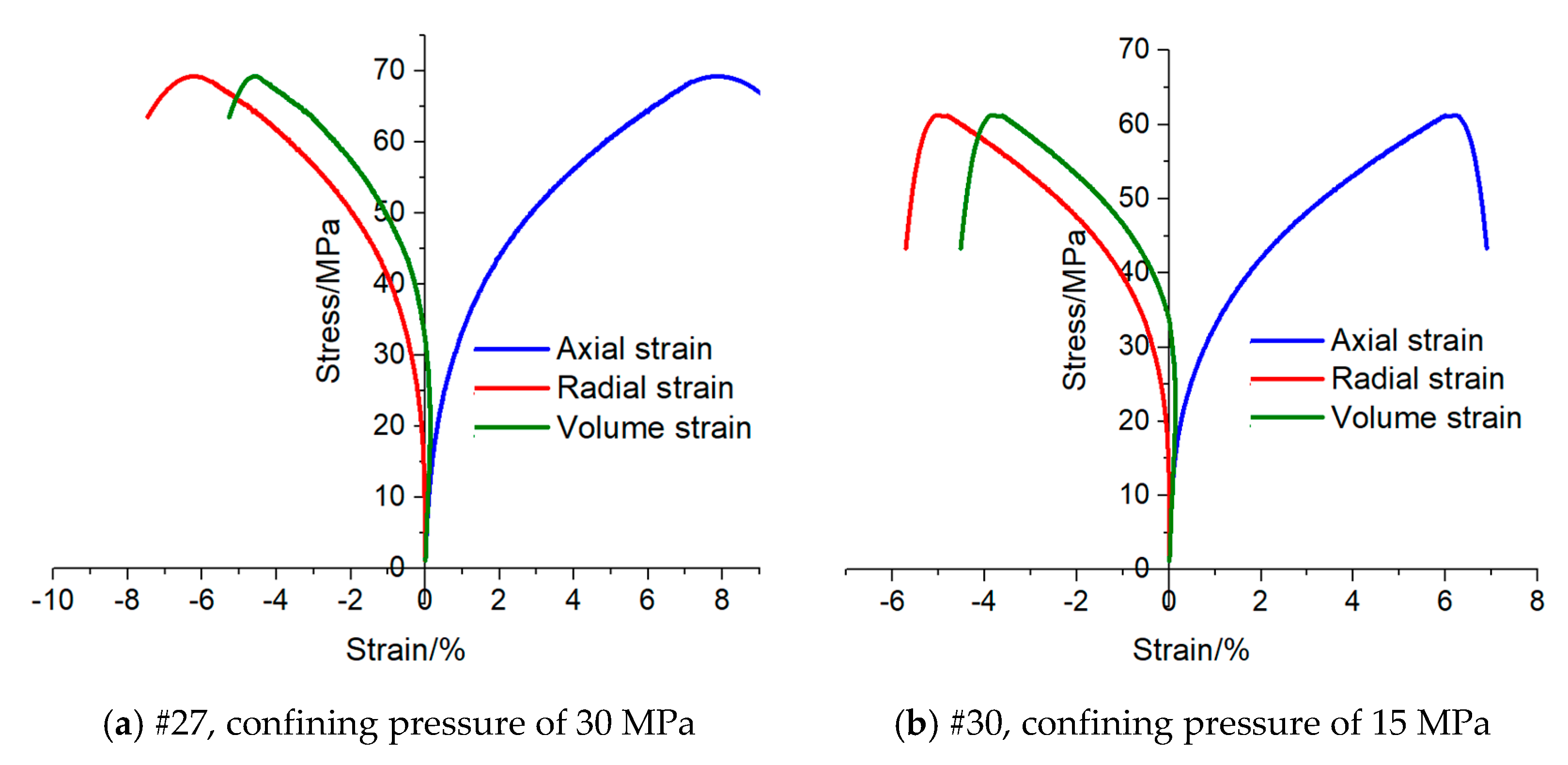
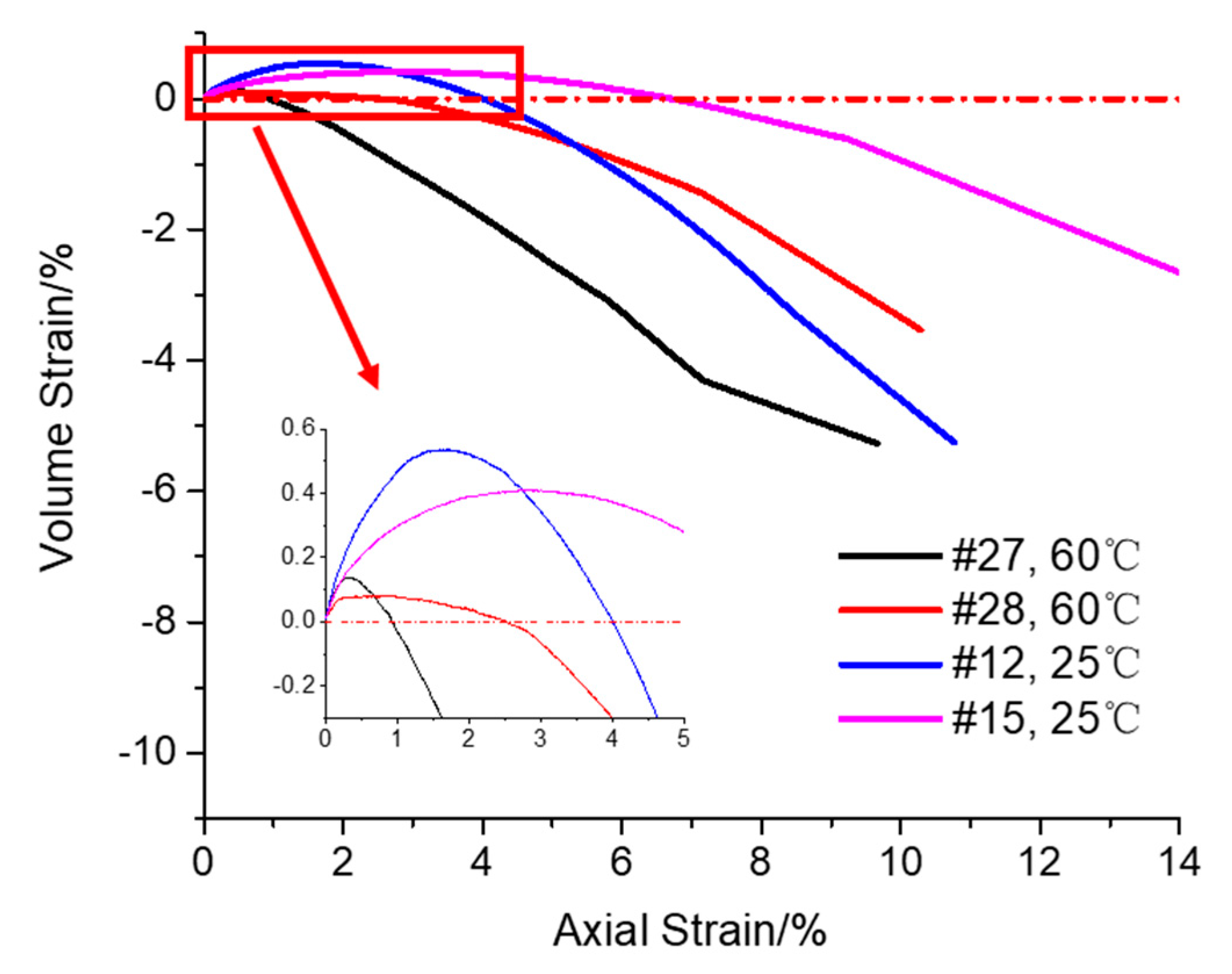
2.2.3. High Temperature Triaxial Test

Liang et al. [28] discussed the influence of temperature on the mechanical properties of salt rock and concluded that the uniaxial compressive strength and axial strain of salt rock increase with increasing temperature, while the elastic modulus decreases. According to the temperature distribution characteristics of Sanshui Basin, this section studies the mechanical deformation behavior of salt rock at 60 °C. The comparison of the experimental data in Table 4 and Table 5 shows that the peak strength decreases slightly with the increase of temperature under 30 MPa confining pressure, and the average decrease is about 8.3% compared with that under normal temperature, indicating that temperature has a certain influence on the mechanical parameters of salt rock. With the increase of temperature, the mechanical parameters of salt rock show a tendency to weaken. Gao et al. [26] believed the thermal stress caused by temperature makes it easy to produce stress concentrations at the boundary of mineral particles which exceed the strength limit of rock, thus causing the connection to fracture between mineral particles at the boundary surface. Thus, microcracks are generated and extend to form a network, finally leading to macroscopic deterioration of rock mechanical properties. Chen [29] believed that the thermal damage of salt rock was mainly caused by intergranular cracks caused by uneven grain expansion. Figure 7 shows the triaxial test curve of some cores under high temperature, and that the stress–strain changing characteristics of cores under different confining pressures are basically the same. Under the action of thermal stress, the higher the confining pressure, the greater the peak load required for the same deformation. Figure 8 shows that the axial deformation required by the salt rock core under the high-temperature environment is smaller when entering the volume expansion stage under the confining pressure of 30 MPa, which also shows that temperature has an impact on the deformation of the salt rock. From the microscopic point of view, with the increase of temperature, the thermal movement of molecules inside the salt rock is enhanced, the cohesion between molecules is weakened, and the indirect contact surfaces of grains are more prone to slippage. In addition, the different thermal expansion coefficients between grains lead to more damage cracks, deteriorated mechanical properties of the salt rock. It is easier to achieve damage under load compared with the normal temperature state. As a whole, the salt rock in Sanshui Basin, Guangdong Province is not significantly affected by temperature.

2.2.4. Creep Test

The rheological properties of salt rock are of great significance to the long-term operational safety of underground projects. Figure 9 shows the pre and post creep test photos of some salt rock cores in Sanshui Basin under uniaxial and triaxial conditions. The creep test did not cause large apparent damage to the salt rock core. After the test, the rock core appears to be complete, and there were no fractures or fragmentation. The only difference was in the boundary between particles, which appeared clearer and more obvious (as shown in the red dotted ellipse in Figure 9a below). Under the uniaxial creep test, the creep rate increases with the increase of axial pressure, as shown in Figure 10a. Table 6 shows that the accelerated creep stage occurs in uniaxial creep of individual cores, such as core #18 under an axial pressure of 24 MPa and core #20 (as shown in Figure 10b) under an axial pressure of 20 MPa, while individual cores (such as #17) still do not enter the accelerated creep stage under an axial pressure of 25 MPa, reflecting the heterogeneity of the stratum, indicating that there are differences in properties of salt rocks even in the same mining area.
The confining pressure of the triaxial creep test was set according to the stress state of the coring formation depth. Under the triaxial creep test, the deviatoric stress is in direct proportion to the creep rate. The greater the deviatoric stress, the greater the creep rate (as shown in Table 6). When the confining pressure is fixed, the salt rock does not enter the accelerated creep stage with the increase of deviatoric stress. Even if the deviatoric stress reaches 35 MPa, there is no accelerated creep phenomenon, indicating that the confining pressure has a significant limiting effect on the salt rock creep. According to Figure 11, the fitting results of creep rate show that the creep rate is exponential with the deviatoric stress.
Seen from the comparison of triaxial test results at room temperature and high temperature, the target formation temperature of 60 °C in Sanshui Basin has a slight impact on the strength properties of the salt rock. In order to explore the influence of the temperature on the creep property of salt rock, a creep test (core No. #32) was conducted at 60 °C and compared with triaxial creep data under the same confining pressure and deviatoric stress at the room temperature, as shown in Figure 12. The compared results of creep rate show that, under the same deviatoric stress and confining pressure, the effect of temperature on creep rate is not significant. The creep rate of salt rock, under the confining pressure of 30 MPa, deviatoric stress of 25 MPa and environmental temperature of 60 °C in the target salt layer of Sanshui Basin, has little difference from the rate under the same conditions at room temperature. Therefore, the influence of temperature can be ignored when analyzing the creep problem.

2.3. Result Analysis and Dicussion

2.3.1. Strength Model Parameters of Salt Rock

The results of uniaxial and triaxial compression tests of salt rock in Sanshui Basin show that the failure mode of salt rock under uniaxial compression is tensile failure, while the failure mode is radial expansion failure without obvious shear fracture under triaxial compression. A lot of research [30,31] shows that the strength of salt rock can be expressed by the Mohr–Coulomb strength criterion:
1 2 ( σ 1 σ 3 ) = C cos φ 1 2 ( σ 1 + σ 3 ) sin φ
where σ 1 ,   σ 3 are maximum and minimum principal stresses, respectively; C is cohesive force; φ is internal friction angle.
Based on the uniaxial and triaxial compression test results in Sanshui Basin, the cohesion and internal friction angle of salt rock at room temperature are 8.32 MPa and 28.1°, respectively. By comparing Yingcheng Salt Mine and Jintan Salt Mine [32], as shown in Table 7, the cohesion of salt rock in Sanshui Basin is slightly greater than those of Yingcheng Salt Mine and Jintan Salt Mine, while the internal friction angle is slightly lower than those of the latter two. Cohesion reflects the strength of material. Here, the smaller the cohesion, the lower the rock strength. The influence of internal friction angle on rock strength is greater than that of cohesion [33]. From the comparison results of strength parameters, the strength of salt rock in Sanshui basin is between that of the Yingcheng and the Jintan salt mines in Hubei.
The high temperature compression test of salt rock shows that the temperature has a slight deterioration effect on the mechanical properties of salt rock. In the design and application of engineering parameters, the temperature factor can be ignored.

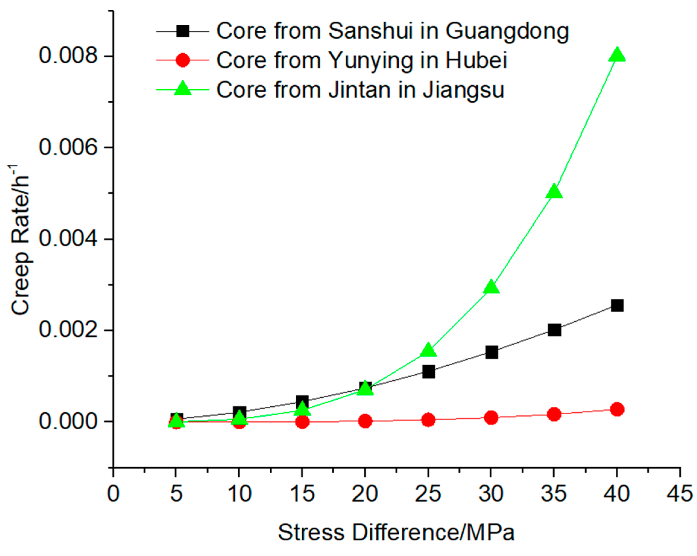
2.3.2. Creep Model Parameters of Salt Rock

Yang et al. [34], based on a large number of studies on the creep properties of salt rock, have come to the conclusion that the steady creep rate of salt rock is closely related to the deviatoric stress and confining pressure. Without considering the influence of temperature, steady state creep model of salt rock conforms to the Norton exponential function:
ε ˙ c r = A ( σ 1 σ 3 ) n
where ε ˙ c r is the creep strain rate; A , n are the material characteristic parameters of salt rock.
By fitting the steady-state creep rate of salt rock samples under 30 MPa confining pressure in Sanshui Basin with the Norton steady-state creep model (as shown in Figure 11), the creep model parameters A and n were calculated to be 3.61 × 10⁻⁶ and 1.78, respectively. The creep parameters of the salt rock of Jintan Salt Mine in Jiangsu Province and Yunying Salt Mine in Hubei Province [35] are compared (both fitted with the Norton creep model) and shown in Table 8. The results show that the higher the value of n, the higher the sensitivity of steady creep rate to the variation of deviatoric stress. The smaller the A value, the lower the sensitivity of steady creep rate to the change of confining pressure. The creep model parameter A of Sanshui basin salt rock is much higher than that of Yunying and Jintan salt rock, while n is lower. Figure 13 shows the comparison of creep strain rates under different deviatoric stresses. When the deviatoric stress is lower than 20 MPa, the creep rate of salt rock in Sanshui Basin, Guangdong Province is the highest under the same confining pressure. When the deviatoric stress exceeds 20 MPa, it is between the creep rates of Yunying in Hubei Province and Jintan in Jiangsu Province.

3. Mechanical Stability Evaluation

The rock strata in the salt cavern area of the reservoir rock and its overburden and floor rock strata can be considered as an approximately horizontal distribution, so its tectonic stress is weak. The vertical component of the original geostress of the stratum in this area is calculated according to the average density of the overlying strata and the relationship between the average density and the burial depth of the rocks in each layer of the calculation area, and according to the calculation method of self-weight stress. It is thought that after a long period of tectonic evolution, the three components of the stresses are equal in the salt formation. According to the above rock mechanics analysis, the stability evaluation and analysis are carried out for the salt cavern gas storage to be built in the salt layer in this area. The finite difference software Flac3D [36] (Flac3D vs. 6.0, Itasca Consulting Group Inc., Minneapolis, MN, USA) was used to establish the geomechanical model and perform the simulation, which is widely used to handle rock and soil engineering problems for its outstanding ability and advantage to solve large displacement problems. The Cpower model was introduced into the simulation to describe the mechanical behavior of salt cavern gas storage during injection-production operation, which is composed of the Mohr–Coulomb criterion and the Norton Power creep model and widely used in creep engineering of underground excavation.

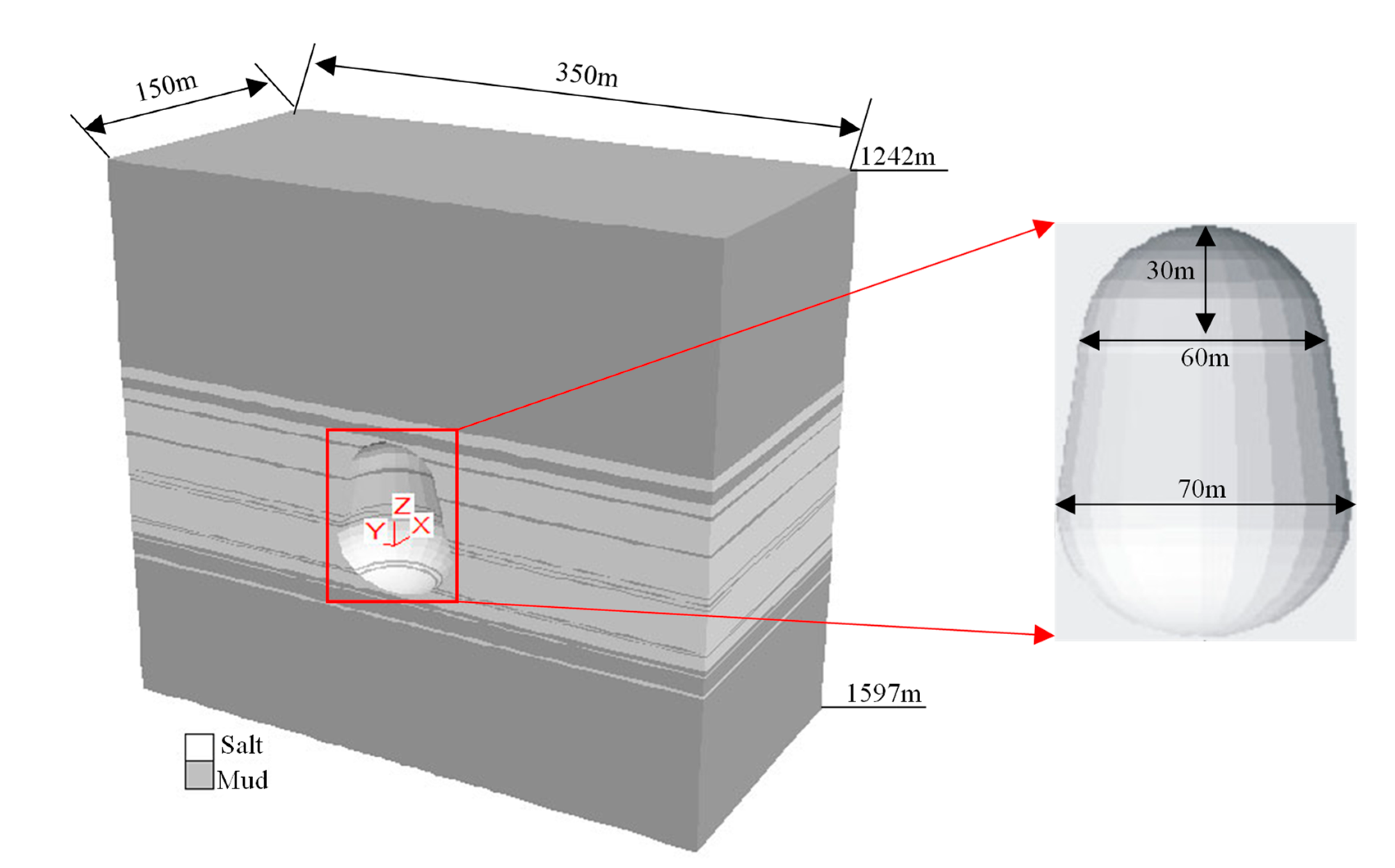
3.1. Geomodel of Salt Cavern Gas Storage

Based on the geological conditions of target strata and previous research results [37,38,39], a pear-shaped cavity was used to construct the salt cavern gas storage in Sanshui Basin. The morphological structure of the salt cavity had a height of 30 m at the top, a diameter of 60 m in the upper hemisphere and 70 m in the lower hemisphere. The whole height of the cavern was 95 m. There were 10 mudstone interlayers distributed in the target salt formation. The corresponding geological model is shown in Figure 14. The hexahedral mesh was used in the model and the sensitivity analysis of its mesh density was done. The model was meshed with a total number of 244,044 elements and 52,112 nodes.
The upper surface of the model (1242 m) was the stress boundary condition and the average density of the overlying strata was 2.5 × 10³ kg/m3. Thus, the vertical load component of the upper boundary (z = 1242 m) of the model was 31.05 MPa. The bottom surface of the model (1597 m) was constrained in the Z-direction, and the four sides in the horizontal direction of the model were constrained by the simple support in the corresponding normal direction. That is, the front, back, left, right and bottom surfaces of the model were considered to have normal constraints, and movement in normal direction was not allowed, and the influence of the cavity mining process on them could be ignored.

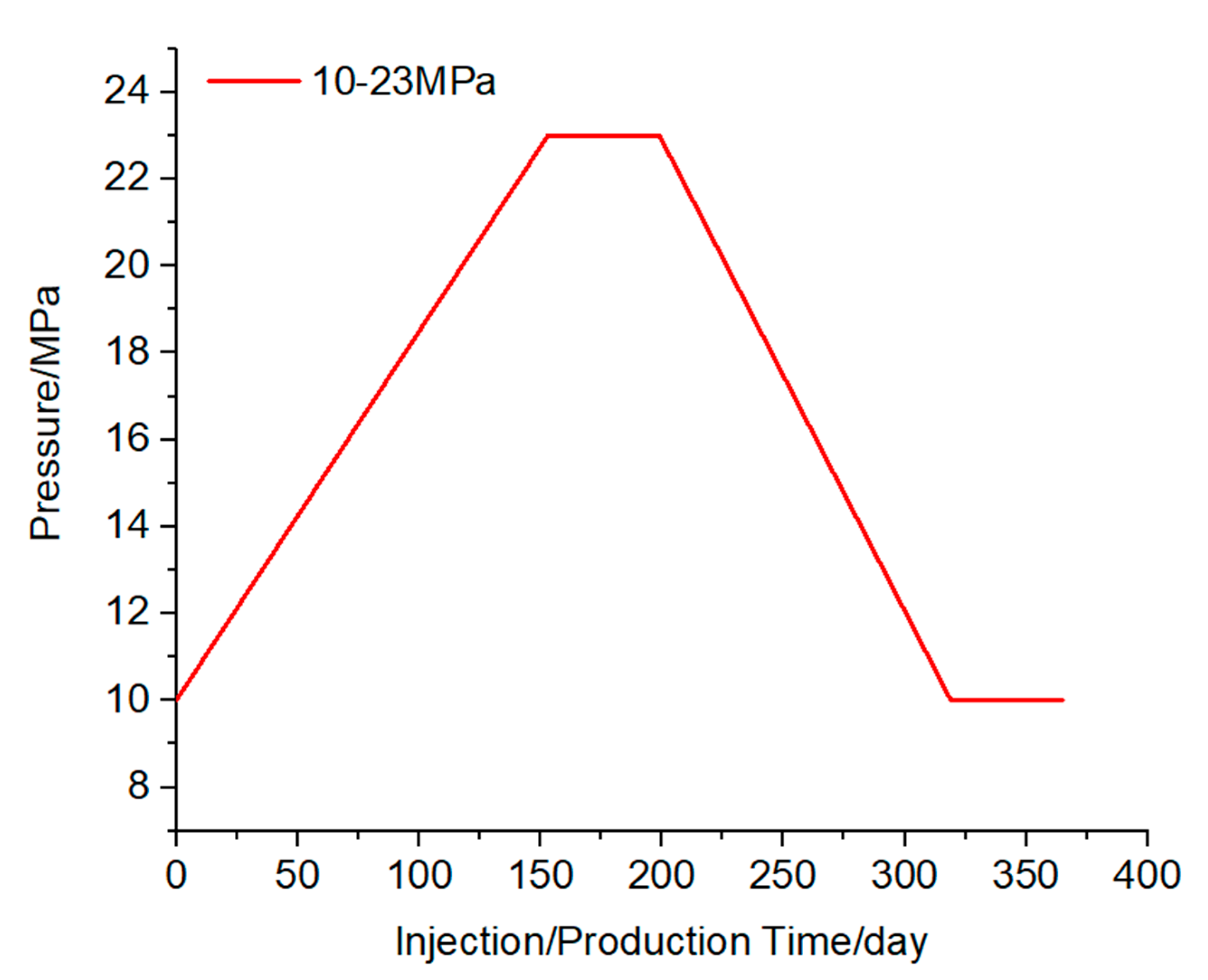
3.2. Injection and Production Pressure Scheme

According to the depth of the last casing and domestic and foreign experience, the upper limit pressure of the designed and constructed salt cavern gas storage was 23 MPa, and the minimum internal pressure is 10 MPa. The injection-production operation simulation is carried out with a service life of 30 years. One cycle consists of four stages of gas injection, well shut in, gas production and well shut in, as shown in Figure 15.

3.3. Stability Analysis

Based on the above rock mechanical parameters and the constitutive model, combined with the injection-production operation scheme, a mechanical stability analysis of single cavity and cavity group was carried out to determine the feasibility of the construction of salt cavern gas storage. The parameters of rock mass layers are listed in Table 9.

3.3.1. Stability Evaluation Criterion

An index system composed of displacement, plastic zone, volume shrinkage and vertical stress was summarized to evaluate the safety of salt cavern UGS during the stability analysis. The displacement of cavity surrounding rock increases with the operation time caused by the rock salt creep. The allowed displacement was not over 5% of the maximum cavern diameter [40]. The Mohr–Coulomb criterion, one of the most extensively used criteria in geotechnical engineering, was used to judge whether the cavity surrounding rock enters the plastic failure state. The expression is shown in Equation (1). Volume shrinkage was used to characterize the reduction ratio of cavity volume loss to its original volume. The allowed ratio is 30% after operating 30 years according to much research on salt cavern gas storage and the geological data of Sanshui Salt Mine.

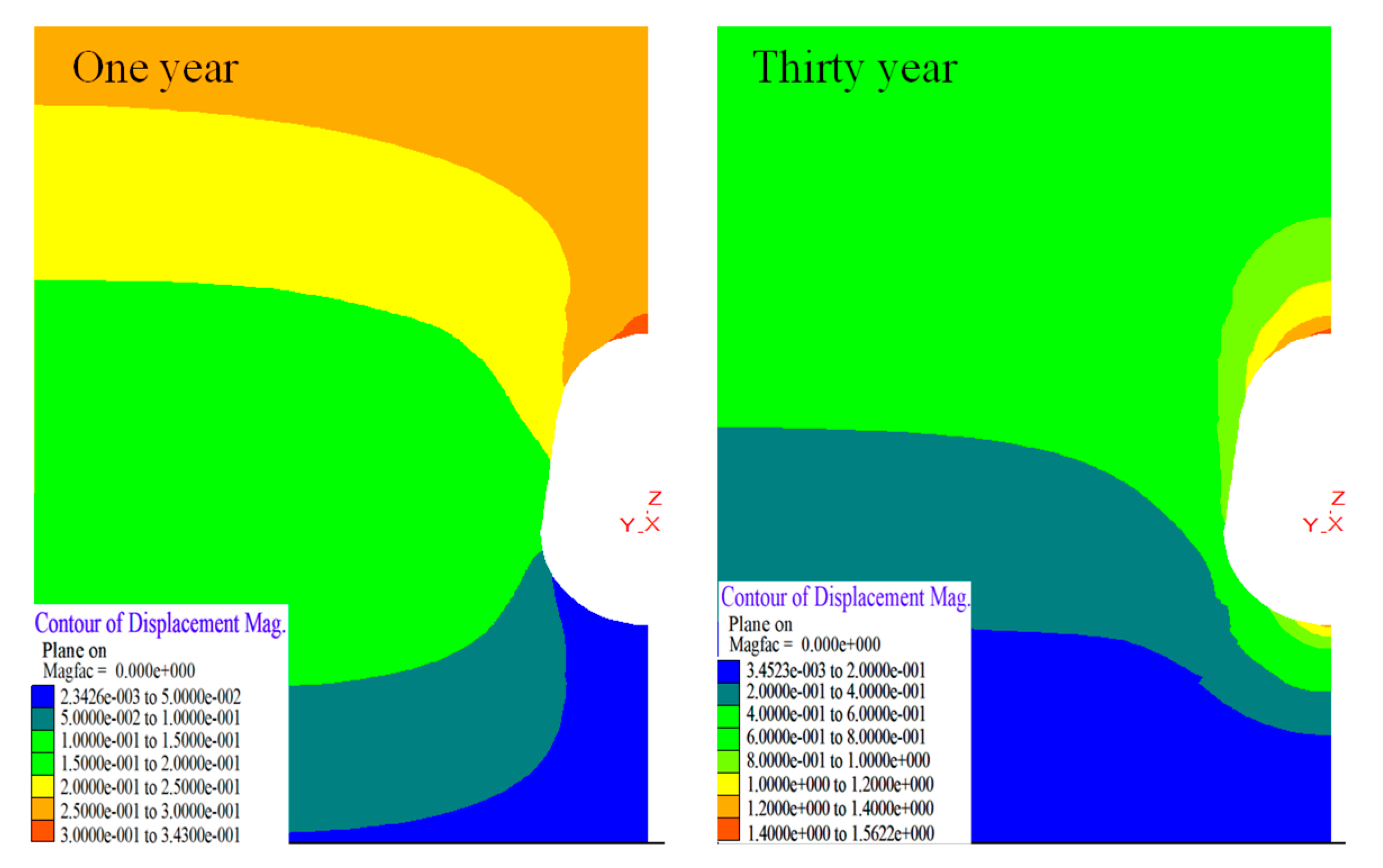
3.3.2. Single Cavity Stability Analysis

Figure 16 and Figure 17 show the deformation and plastic zone of surrounding rock in the first year and the 30th year of salt cavity creep after gas production in that year. The roof displacement in the first year is relatively large, about 0.32 m. The deformation of the lower sphere of the cavity is small. The plastic zone is mainly concentrated on the positions of each interlayer and the cavity top and bottom, and the depth of the plastic zone of the interlayer and bottom area in the middle of the cavity is large. In the 30th year, the top and bottom parts both deform towards the interior of the cavity and the large displacement is concentrated near the top and bottom position, with maximum displacement of about 1.57 m. The plastic zone is essentially the same as the first year, and the volume of the plastic zone changes slightly.
According to Wang’s research [40], the displacement of the cavity top should not exceed 5% of the maximum diameter of the salt cavity. After 30 years of operation, the cavity top settlement displacement is about 1.57 m (as shown in Figure 18), which is 2.2% of the largest diameter (70 m) of the cavity, indicating that the stability of the cavity is good under the operating pressure. Figure 19 shows the volume convergence of the chamber under different operation times. After 30 years of operation, the volume convergence rate of the cavity is 6.55%, which meets the stability requirement that the volume convergence rate should not exceed 5% during 5 years of operation. Similarly, it reflects the good stability characteristics of the cavity.

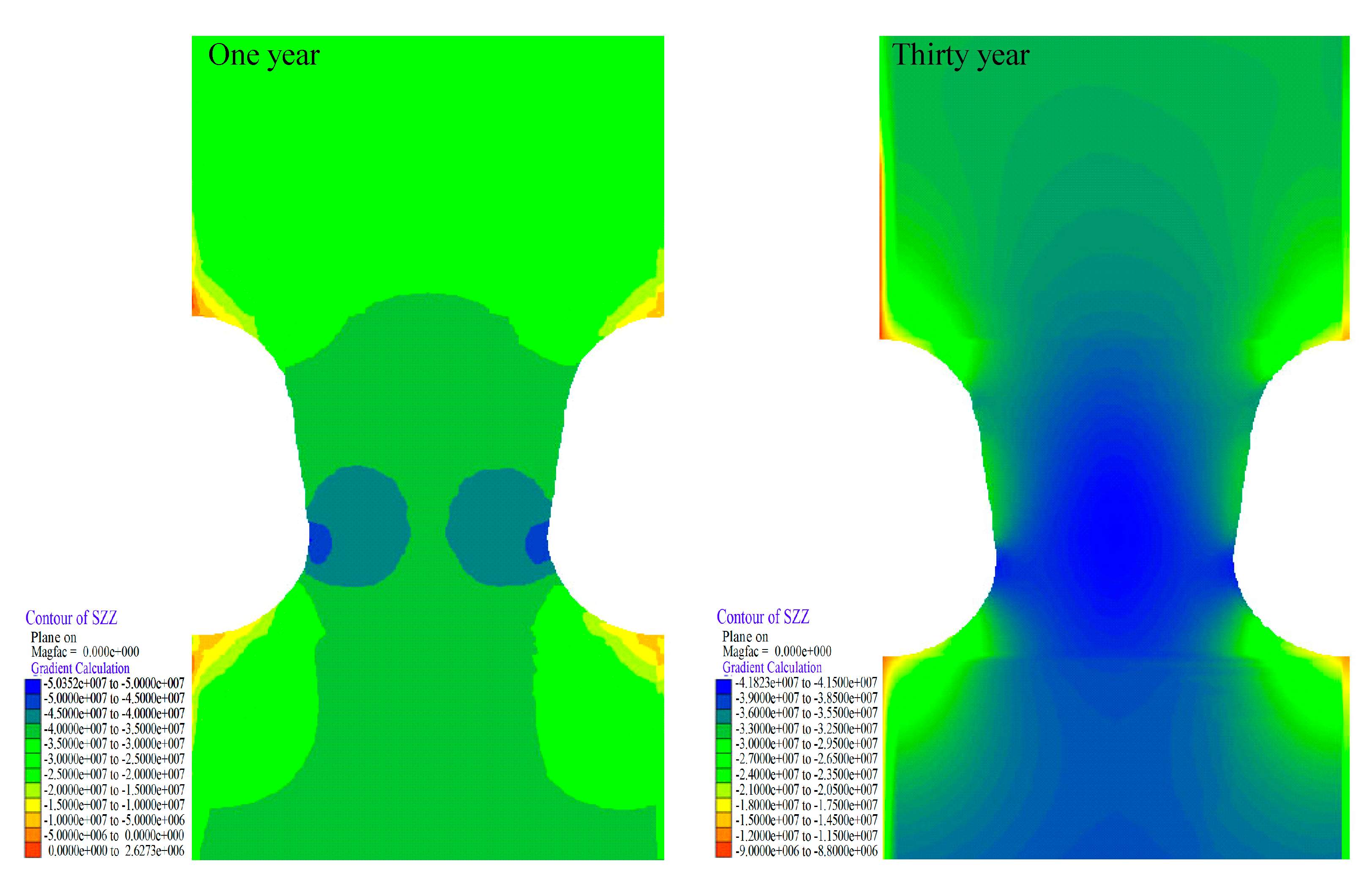
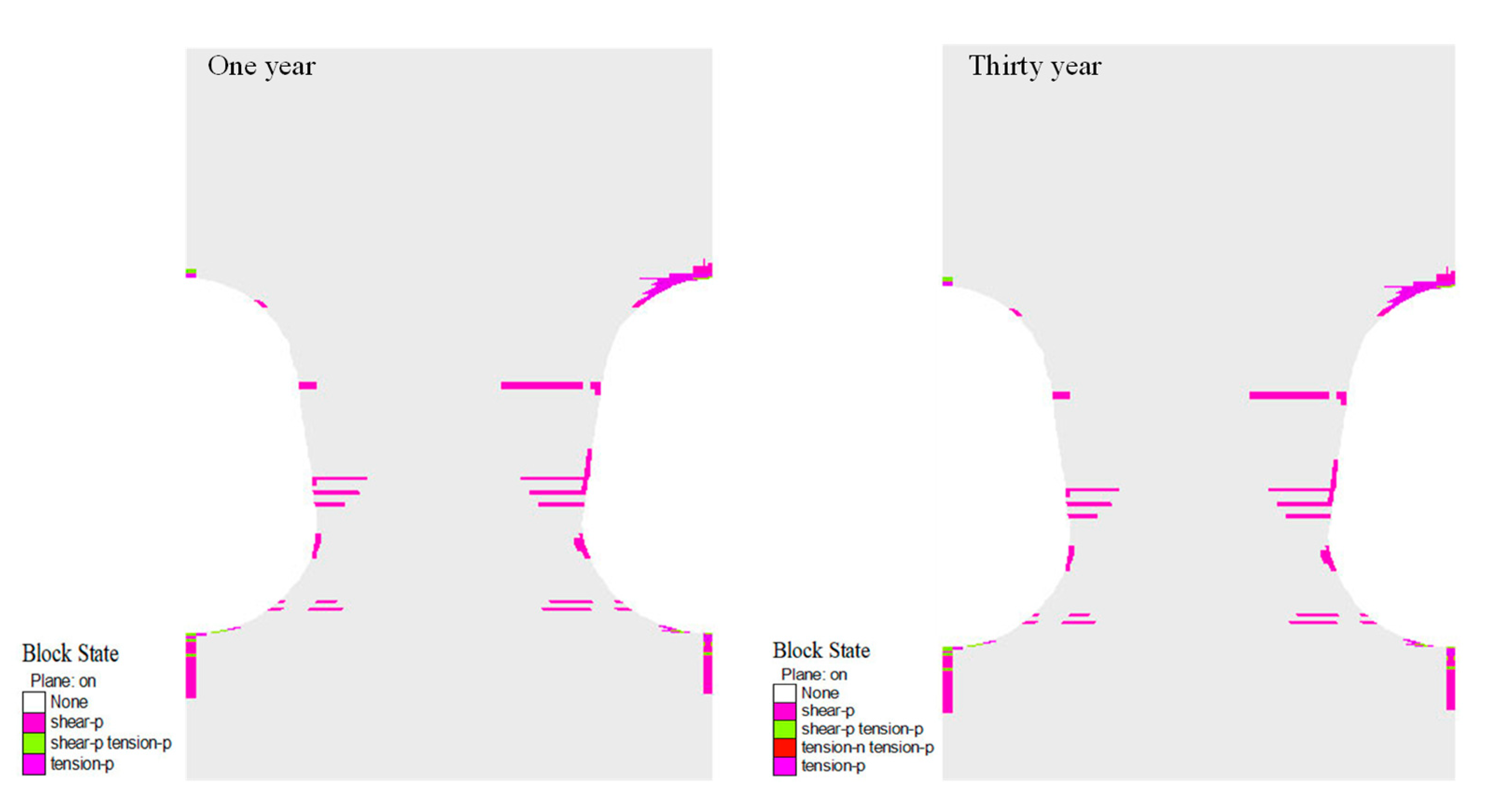
3.3.3. Stability Analysis of Two Caverns

For the construction of salt cavern storage cavern group, the minimum safety distance of adjacent caverns should be considered. The layout of the multi cavern is recommended to be in a positive triangle layout, and the pillar design of each adjacent cavern should be equal [41]. Therefore, the problem can be simplified to only analyze two adjacent caverns. Figure 20 shows the design width of adjacent storage pillars, where D is the maximum diameter of any cavity. The designed well spacing of Sanshui Basin is 250 m, and the pillar width is 2.14D, so the pillar width is considered as a 2D working condition. The maximum operating pressure for the numerical simulation of injection-production operation of tunnel group is 23 MPa, the minimum is 10 MPa, and the operating time is 30 years.
Figure 21 and Figure 22 show the vertical stress and plastic zone of surrounding rock in the first year and the thirtieth year after gas production. The stress distribution is basically symmetrical along the vertical centerline of the pillar. In the first year, the stress at the top and bottom of the cavity is relatively small, while the stress at the minimum spacing is relatively large. The plastic zone is distributed asymmetrically. The plastic zone of the surrounding rock of the roof of the right cavity is significantly larger than that of the surrounding rock of the left cavity. The plastic zone is mainly concentrated in each interlayer, the cavity top and bottom. The failure mode is mainly shear failure, and the plastic zone of the pillar is not connected. The extreme value of vertical stress decreases in the thirtieth year. The distribution of plastic zone is similar to that of the first year, and the volume of plastic zone changes slightly. During the overall operation, the convergence rate of two cavities meets the requirement that the convergence rate is less than 10% in ten years [42], shown in Figure 23, and the pillar design is reasonable.

4. Conclusions

In this paper, the salt rock of a salt mine in Sanshui Basin of Guangdong Province was taken as the subject of research. Direct and indirect tensile, uniaxial compression, triaxial compression and creep tests were carried out. At the same time, the influence of temperature was considered to study the mechanical properties of the salt rock of the salt mine. A stability evaluation of salt cavern gas storage under injection-production operation conditions was conducted based on actual formation conditions. The main conclusions are as follows:
  • The salt rocks in Sanshui Basin generally contain impurities. Both tensile test methods show that the tensile strength of the salt rock is low, less than 2 MPa.
  • Under uniaxial compression, the circumferential tensile stress of the core is greater than its own tensile strength. The failure mode of salt rock presents as radial tensile failure and axial splitting failures. However, under triaxial compression, the salt rock shows a radial expansion state without obvious shear splitting. The confining pressure significantly improves the compressive strength of salt rock by limiting its radial deformation.
  • The mechanical properties of salt rock are slightly influenced by temperature. With the increase of temperature, the peak strength and elastic modulus of salt rock decrease, and axial deformation at peak failure also reduce. Under the confining pressure of 30 MPa, the strength of salt rock decreases by 4.5% at the temperature of 60 °C compared with that at room temperature.
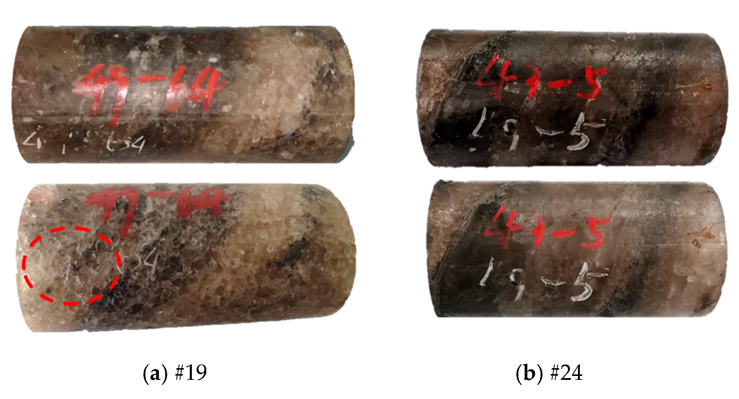
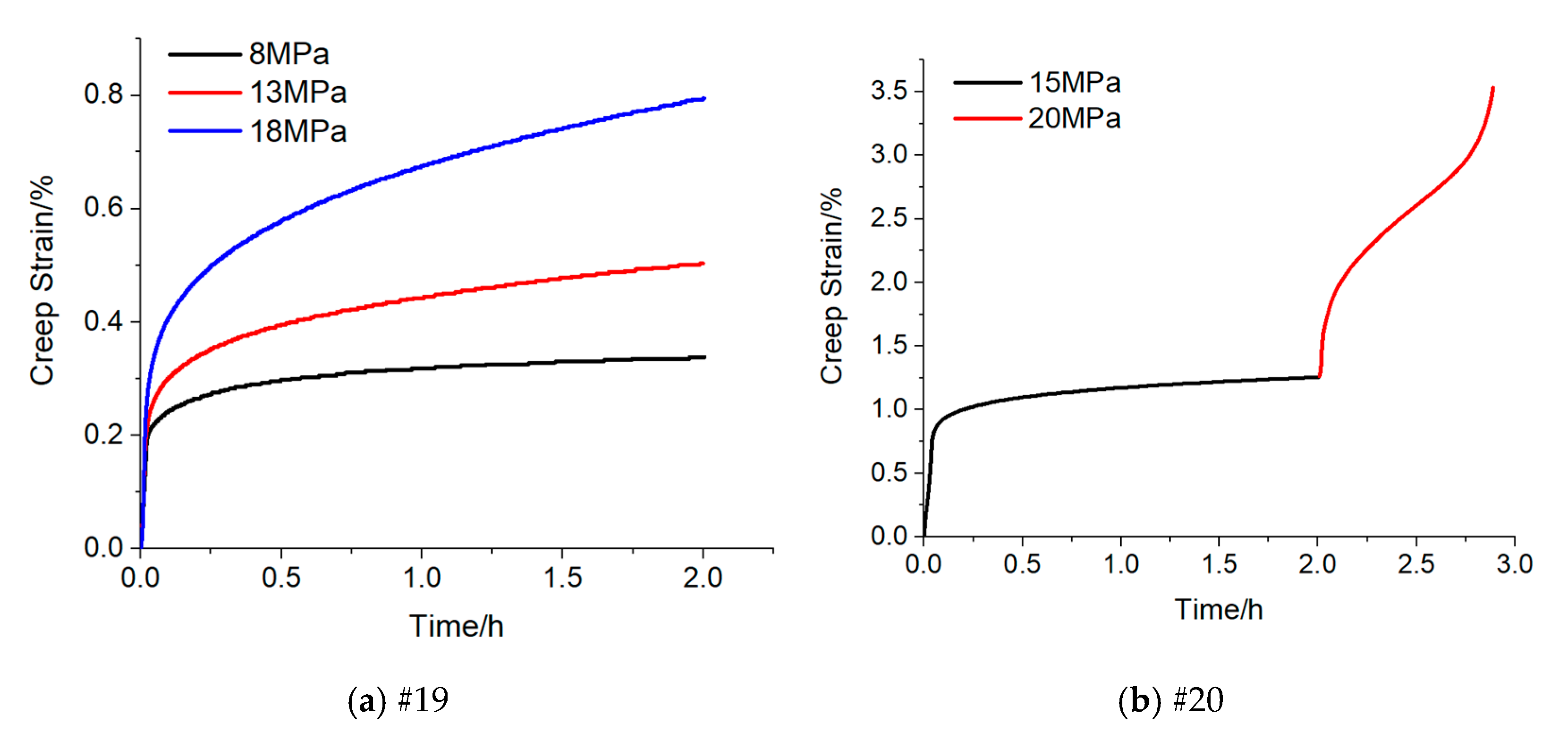
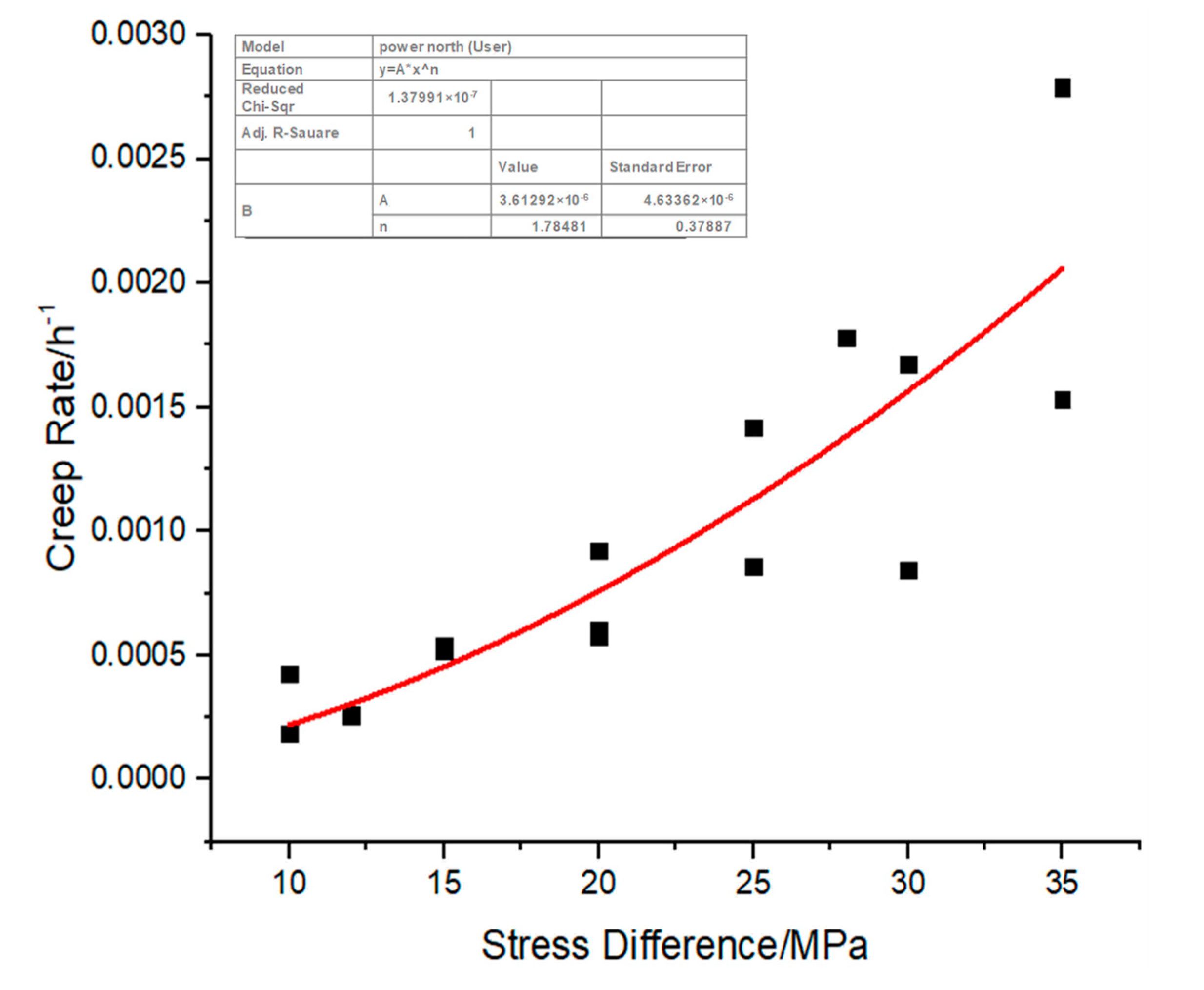
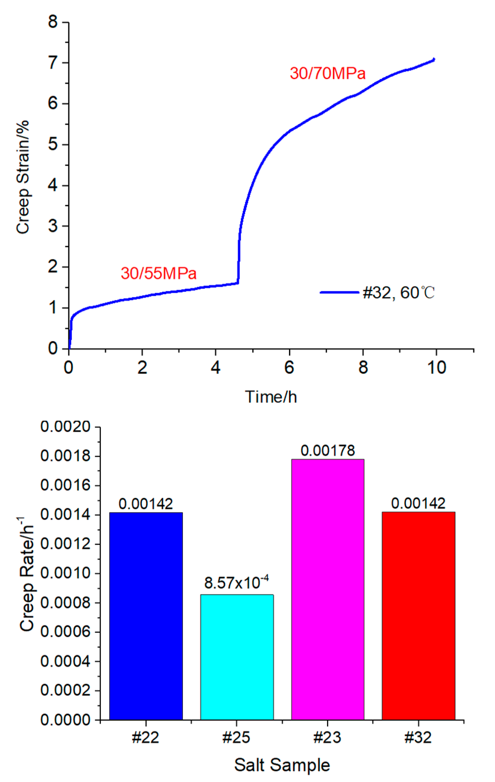
  • Whether under uniaxial or triaxial compression condition, the salt rock after creep test has no obvious collapse failure. With the increase of axial load, the accelerated creep of salt rock only occurs under uniaxial compression operation, indicating that the confining pressure has a certain inhibition effect on the creep of salt rock. The greater the deviatoric stress, the greater the creep rate of salt rock, which conforms to the power exponent relationship. An operating temperature of 60 °C has no obvious influence on the creep rate of the salt rock. On the whole, the salt rock of salt bearing strata in Sanshui Basin, Guangdong Province, shows good mechanical properties.
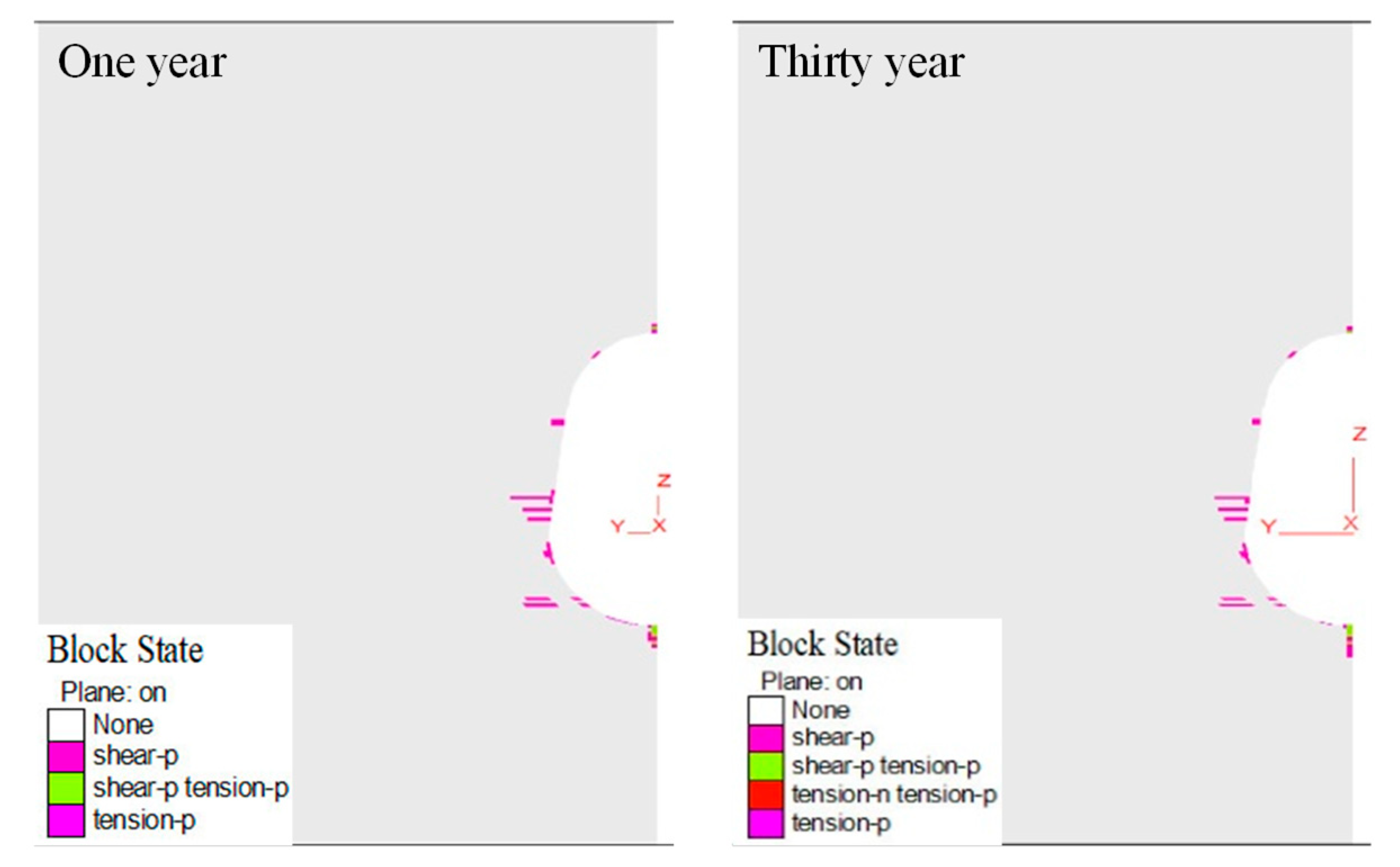
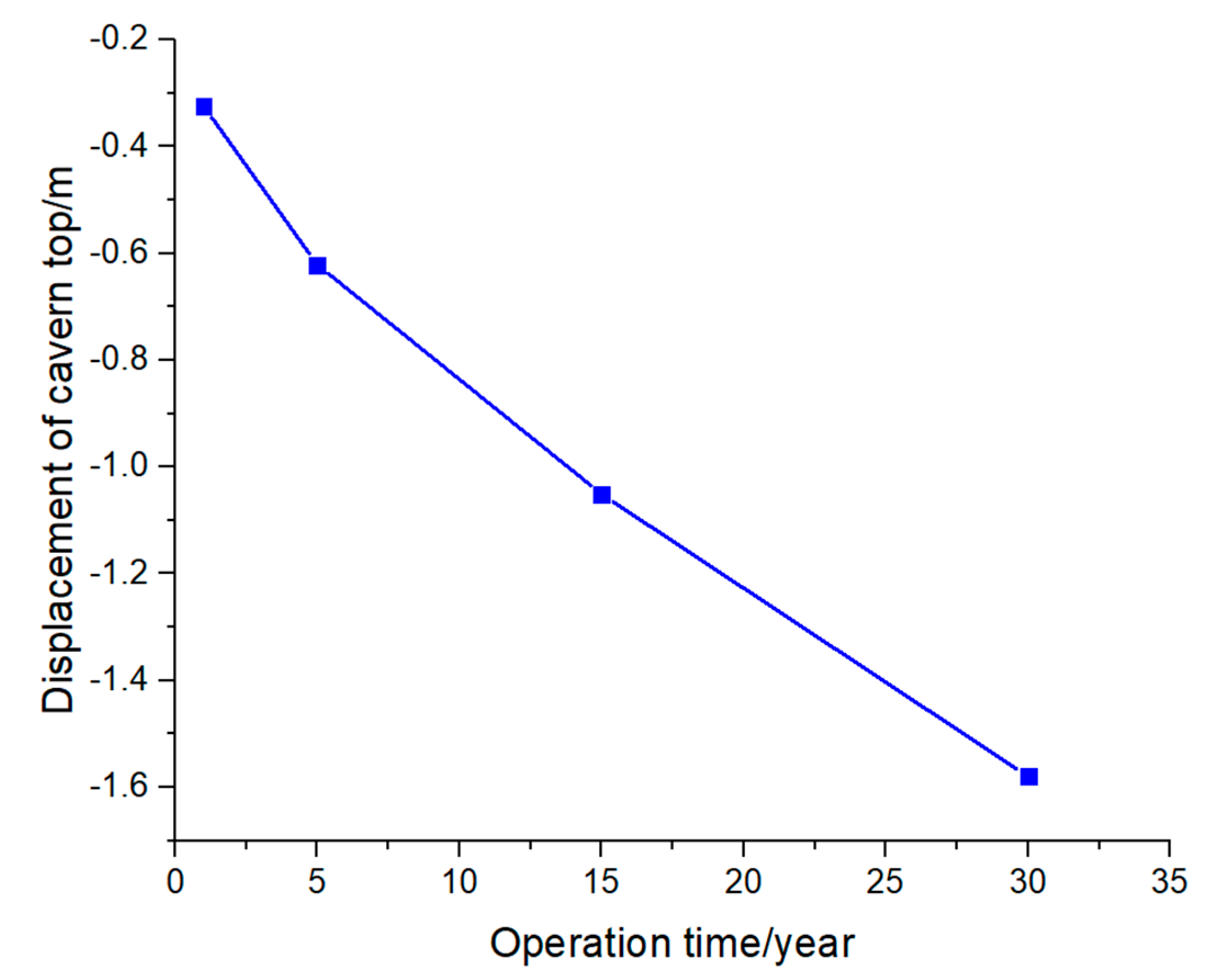
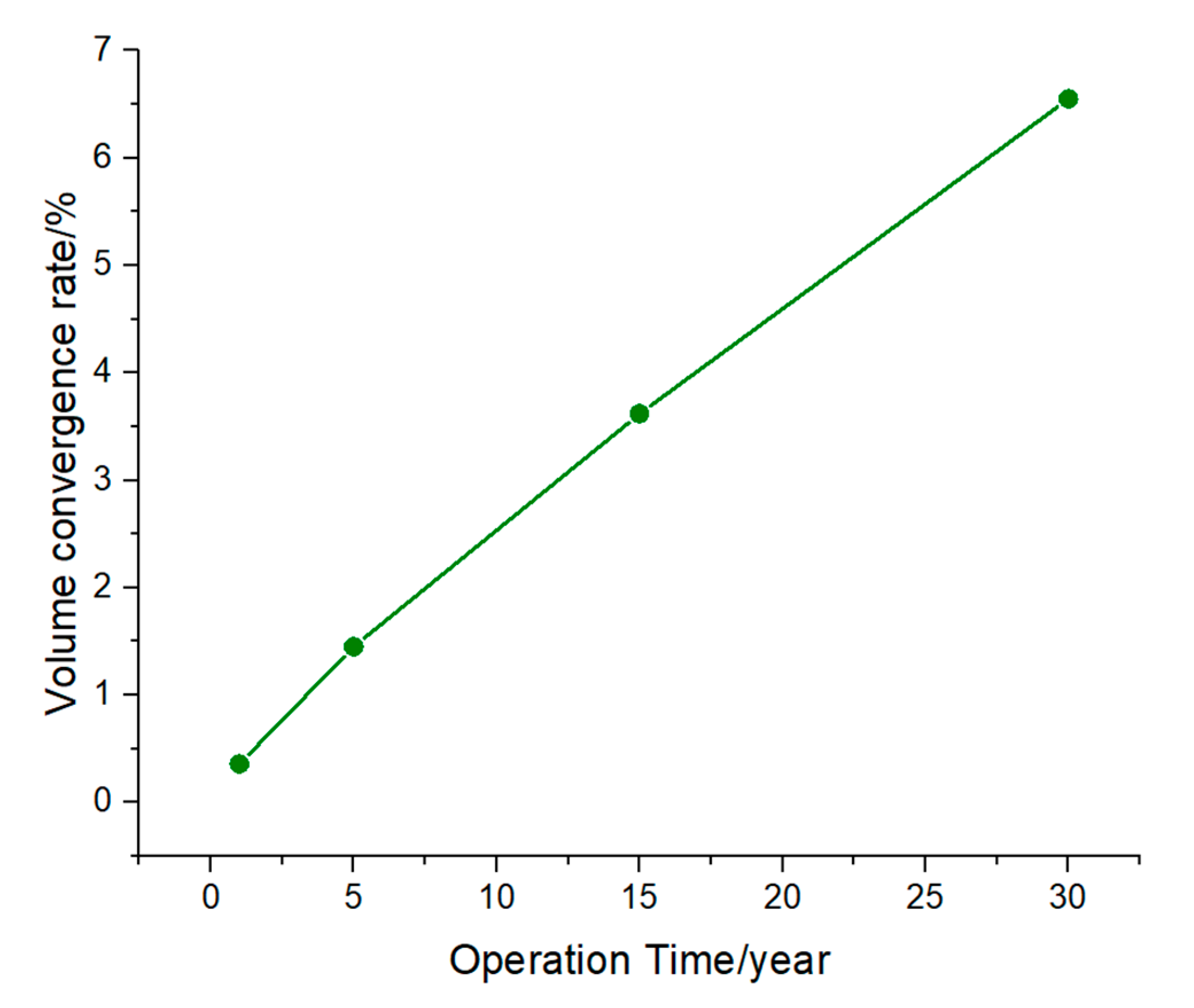
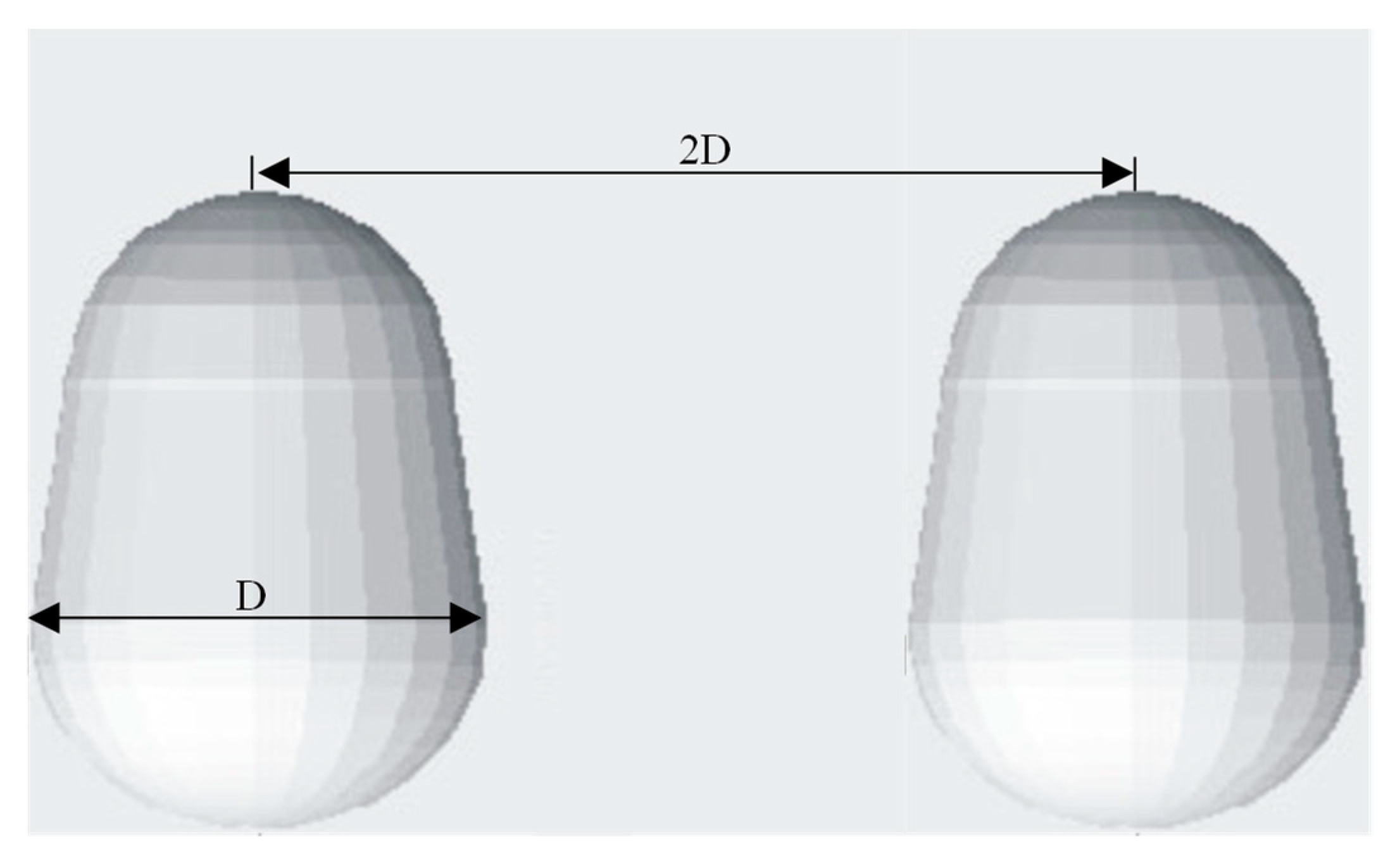
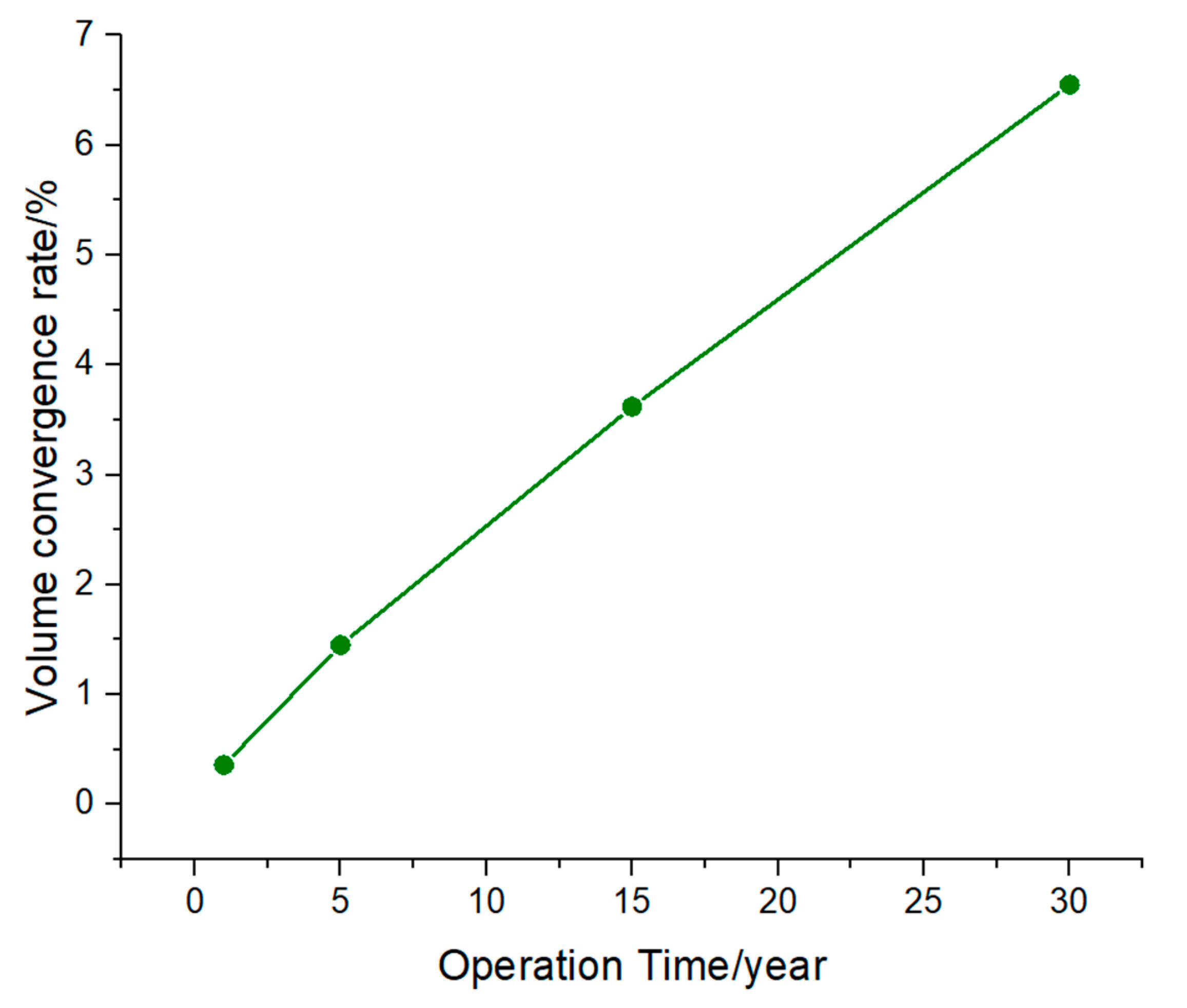
  • Under the operating pressure of 10–23 MPa, the roof settlement displacement and the volume convergence rate of the cavity are small. Moreover, the plastic area between two caverns is unconnected, and the overall stability of the salt cavity is good. Combined with the results of mechanical experiments and a stability analysis, the salt formation of Sanshui Basin in Guangdong Province has a good geomechanical condition, and it is suitable for the construction of underground salt cavern gas storage.

Author Contributions

Conceptualization, J.D.; Methodology, J.D.; Validation, K.L.; Formal analysis, Y.K., S.B. and J.W.; Investigation, H.L., K.L. and L.R.; Data curation, S.B.; Writing—original draft, H.L.; Writing—review & editing, Q.W. and Y.K.; Visualization, L.R. and J.W.; Supervision, G.D. All authors have read and agreed to the published version of the manuscript.

Funding

This research was funded by Major Scientific and Technological Projects of China, grant number No2022DJ8303.

Institutional Review Board Statement

Not applicable.

Informed Consent Statement

Not applicable.

Data Availability Statement

The study did not report any data.

Conflicts of Interest

The authors declare no conflict of interest.

References

  1. Ding, G.; Zhang, B.; Yang, C.; Xie, P.; Tian, G. The Creep Deformation Rule of Gas Storage Salt Cavern. Nat. Gas Ind. 2007, 27, 94–96. [Google Scholar]
  2. Crotogino, F.; Schneider, G.-S.; Evans, D.J. Renewable energy storage in geological formations. Proc. Inst. Mech. Eng. Part A J. Power Energy 2017, 232, 100–114. [Google Scholar] [CrossRef]
  3. Ran, L.N.; Zheng, D.W.; Han, B.J.; Wang, Y.; Kou, Y.X. Overview and Development of Energy Storage Using Salt Caverns in the World. In Proceedings of the 2013 National Natural Gas Academic Annual Conference, Kunming, Yunnan, China, 14–15 August 2013; pp. 440–445. [Google Scholar]
  4. Zheng, Y.L.; Zhao, Y.J. General Situation of Salt Cavern Gas Storage Worldwide. Oil Gas Storage Transp. 2010, 29, 652–655. [Google Scholar]
  5. Li, N.N.; Zhao, Y.Q.; Wang, T.T.; Yang, C.H. Trends Observation: Strategy and Development of International Salt Cavern Energy Storage Research. Bull. Chin. Acad. Sci. 2021, 36, 1248–1252. [Google Scholar]
  6. Khan, S.A.; Igoshin, A.I.; Sokhranskiy, V.B. Some Technological Aspect of Compressed Helium Storage in Salt Caverns. In Proceedings of the SMRI Spring 2011 Technical Conference, Galveston, TX, USA, 18–19 April 2011. [Google Scholar]
  7. IEA U.S. Underground Natural Gas Storage Capacity 2020 [EB/OL]. Available online: https://www.eia.gov/dnav/ng/ng_stor_cap_dcu_nus_a.htm (accessed on 25 December 2020).
  8. Zhang, B.; Lv, B.L.; Wu, Y.H.; Cui, L.H.; Zhou, S.Q. Development and Trend of Salt-Cavern Gas Storage in Domestic and Abroad. China Well Rock Salt 2021, 52, 21–24. [Google Scholar]
  9. Sedaee, B.; Mohammadi, M.; Esfahanizadeh, L.; Fathi, Y. Comprehensive modeling and developing a software for salt cavern underground gas storage. J. Energy Storage 2019, 25, 100876. [Google Scholar] [CrossRef]
  10. Moghadam, S.N.; Nazokkar, K.; Chalaturnyk, R.J.; Mirzabozorg, H. Parametric assessment of salt cavern performance using a creep model describing dilatancy and failure. Int. J. Rock Mech. Min. Sci. 2015, 79, 250–267. [Google Scholar] [CrossRef]
  11. Stern, N.; Xie, C. China’s new growth story: Linking the 14th Five-Year Plan with the 2060 carbon neutrality pledge. J. Chin. Econ. Bus. Stud. 2022, 2022, 1–21. [Google Scholar] [CrossRef]
  12. Bruno, M.S.; Durseault, M.B. Geomechanical Analysis of Pressure Limits for Thin Bedded Salt Caverns. In Proceedings of the SMRI Spring Technical Meeting, Banff, AB, Canada, 29–30 April 2002. [Google Scholar]
  13. Bruno, M.S. Geomechanical Analysis and Design Considerations for Thin-Bedded Salt Caverns: Final Report; Terralog Technologies: Arcadia, CA, USA, 2005. [Google Scholar]
  14. Bruno, M.; Dorfmann, L.; Han, G.; Lao, K.; Young, J. 3D geomechanical analysis of multiple caverns in bedded salt. In Proceedings of the SMRI Fall Technical Meeting, Nancy, France, 1–5 October 2005. [Google Scholar]
  15. B’Erest, P.; Brouard, B. Safety of salt caverns used for underground gas storage blow out; mechanical instability; seepage; cavern abandonment. Oil Gas Sci. Technol. 2003, 58, 361–384. [Google Scholar] [CrossRef] [Green Version]
  16. Ma, H.; Yang, C.; Li, Y.; Guo, E.; Liu, J. Experimental and theoretical research on yield and failure characteristics of salt rock. Chin. J. Rock Mech. Eng. 2012, 31, 3747–3756. [Google Scholar]
  17. Liu, X.R.; Guo, J.Q.; Wang, J.B.; Li, P.; Zhang, Q.Q. Investigation on mechanical properties and failure criterion of salt rock based on energy principles. Rock Soil Mech. 2013, 34, 305–310, 315. [Google Scholar]
  18. Alkan, H.; Cinar, Y.; Pusch, G. Rock salt dilatancy boundary from combined acoustic emission and triaxial compression tests. J. Rock Mech. Min. Sci. 2007, 44, 108–119. [Google Scholar] [CrossRef]
  19. Yang, C.; Zeng, Y.; Wu, W.; Chen, F. Constitutive relationship of deep salt rock and its application to petroleum drilling engineering. Chin. J. Rock Mech. Eng. 2003, 22, 1678–1682. [Google Scholar]
  20. Li, Y.; Jiang, W.; Liu, J.; Chen, J.; Yang, C. Direct shear tests for layered salt rocks of Yunying salt mine in Hubei province. Chin. J. Rock Mech. Eng. 2007, 26, 1767–1772. [Google Scholar]
  21. Mansouri, H.; Ajalloeian, R. Mechanical behavior of salt rock under uniaxial compression and creep tests. Int. J. Rock Mech. Min. Sci. 2018, 110, 19–27. [Google Scholar] [CrossRef]
  22. Wanyan, Q.Q.; Wu, J.P.; Wang, Z.Y.; Zheng, Y.L. Experimental study on creep mechanical behaviors of salt rock in gas storage. In Proceedings of the Advances in Rheology—The 11th National Academic Conference on Rheology, Langfang, China, 17–18 October 2012; pp. 281–285. [Google Scholar]
  23. Liu, J. Experimental Investigation and Theoretic Analysis on the Mechanical Properties of Layered Salt Rock; Institute of rock and soil mechanics, Graduate University of Chinese Academy of Sciences: Wuhan, China, 2006. [Google Scholar]
  24. Jiang, D.; Ren, T.; Chen, J.; Ren, S.; Yang, C. Experimental study of mechanical characteristics of molded salt rock with weak interlayer. Chin. J. Rock Mech. Eng. 2012, 31, 1797–1803. [Google Scholar]
  25. Wang, A.M.; Li, X.G.; Yang, C.H.; Huang, Z.Q. Study of interaction between creep deformation of bedded salt rock. Rock Soil Mech. 2010, 31, 3964–3970. [Google Scholar]
  26. Gao, X.P.; Yang, C.H.; Wu, W.; Liu, J. Experimental studies on temperature effect of mechanical properties of salt rock. Rock Soil Mech. 2005, 26, 84–87. [Google Scholar]
  27. Li, Z.; Ma, H.L.; Yao, Y.F. A preliminary study on basic mechanical properties of salt rock at high temperature and high pressure. Chin. J. Undergr. Space Eng. 2013, 9, 981–985. [Google Scholar]
  28. Liang, W.G.; Zhao, Y.S.; Xu, S.G. Testing study on physical and mechanical properties of heated salt rock within 240 °C. Chin. J. Rock Mech. Eng. 2004, 23, 2365–2369. [Google Scholar]
  29. Chen, J.W. Studies on Temperature Effect of Mechanical Properties and Micro Mechanism of Salt Rock; Institute of rock and soil mechanics, Graduate University of Chinese Academy of Sciences: Wuhan, China, 2008. [Google Scholar]
  30. Wang, T.; Yang, C.; Ma, H.; Daemen, J.; Wu, H. Safety evaluation of gas storage caverns located close to a tectonic fault. J. Nat. Gas Sci. Eng. 2015, 23, 281–293. [Google Scholar] [CrossRef]
  31. Yang, C.; Wang, T.; Li, Y.; Yang, H.; Li, J.; Qu, D.; Xu, B.; Yang, Y.; Daemen, J.J.K. Feasibility analysis of using abandoned salt caverns for large-scale underground energy storage in China. Appl. Energy 2015, 137, 467–481. [Google Scholar] [CrossRef]
  32. Liu, J.; Yang, C.; Wen, W.U.; Yinping, L.I. Experiment study on short-term strength and deformation properties of salt rocks. Chin. J. Rock Mech. Eng. 2006, 25, 3104–3109. [Google Scholar]
  33. Liu, D.K.; Li, K.G. The discussion on effect of cohesion and internal frictional angle on the peak strength of rock. Conserv. Util. Miner. Recourses 2015, 3, 16–19. [Google Scholar]
  34. Yang, C.H.; Li, Y.P.; Qu, D.A.; Cheng, F.; Yin, X.Y. Advances in researches of the mechanical behaviors of bedded salt rocks. Adv. Mech. 2008, 38, 484–494. [Google Scholar]
  35. Wang, A.M. The Deformation Mechanism and Nonlinear Creep Constitutive Model of Bedded Salt Rock; Institute of rock and soil mechanics, Graduate University of Chinese Academy of Sciences: Wuhan, China, 2008. [Google Scholar]
  36. Itasca Consulting Group Inc. FLAC3D Version 6.0 Users’ Manual; Itasca Consulting Group Inc.: Minneapolis, MN, USA, 2019. [Google Scholar]
  37. Cyran, K.; Kowalski, M. Shape Modelling and Volume Optimization of Salt Caverns for Energy Storage. Appl. Sci. 2021, 11, 423. [Google Scholar] [CrossRef]
  38. Cyran, K. Insight into a shape of salt storage caverns. Arch. Min. Sci. 2020, 65, 363–398. [Google Scholar]
  39. Onal, E. Stability Analyses of Differently Shaped Salt Caverns for Underground Natural Gas Storage. Master’s Thesis, The Penn-Sylvania State University, State College, PA, USA, 2013. [Google Scholar]
  40. Wang, T.; Yang, C.; Chen, J.; Daemen JJ, K. Geomechanical investigation of roof failure of China’s first gas storage salt cavern. Eng. Geol. 2018, 243, 59–69. [Google Scholar] [CrossRef]
  41. Wang, T.T.; Yan, X.Z.; Yang, H.L.; Yang, X.J. Stability analysis of pillars between bedded salt cavern gas storages. J. China Coal Soc. 2011, 36, 790–795. [Google Scholar]
  42. Li, H.; Deng, J.; Wanyan, Q.; Feng, Y.; Lenwoue, A.; Luo, C.; Hui, C. Numerical Investigation on Shape Optimization of Small-Spacing Twin-Well for Salt Cavern Gas Storage in Ultra-Deep Formation. Energies 2021, 14, 2859. [Google Scholar] [CrossRef]
Figure 1. Core pillar and standard rock sample for experiment (a) for core pillar, (b) for standard core.
Eng 03 00048 g001
Figure 2. Schematic diagram of tensile test (a) for direct tensile, (b) for indirect tensile.
Eng 03 00048 g002
Figure 3. Tensile test photos of salt rock. (a) #5 direct tension (b) #1 indirect tension (left Before experiment, right after experiment).
Eng 03 00048 g003
Figure 4. Photos of some rock cores before and after uniaxial and triaxial compression test. The upper part is before the test, and the corresponding lower part is after the test.
Eng 03 00048 g004
Figure 5. Uniaxial and triaxial stress-strain curves of salt rock in Sanshui Basin.
Eng 03 00048 g005
Figure 6. Relationship between stress and axial strain under different confining pressures in triaxial compression test.
Eng 03 00048 g006
Figure 7. Triaxial compression experimental data of salt rock at high temperature.
Eng 03 00048 g007
Figure 8. Comparison of axial strain and volumetric strain of salt rock at room temperature and high temperatures under confining pressure of 30 MPa.
Eng 03 00048 g008
Figure 9. Photos of some salt rocks before and after creep tests under uniaxial and triaxial conditions.
Eng 03 00048 g009
Figure 10. Results of uniaxial creep tests.
Eng 03 00048 g010
Figure 11. Fitting of creep rate dependence on stress difference under confining pressure of 30 MPa.
Eng 03 00048 g011
Figure 12. Experimental curve of triaxial creep of salt rock samples at high temperature, and the comparison of its creep rate with that at normal temperature.
Eng 03 00048 g012
Figure 13. Comparison of creep strain rates under different stress difference.
Eng 03 00048 g013
Figure 14. Geomechanical model of salt cavern gas storage (half model).
Eng 03 00048 g014
Figure 15. Pressure scheme of injection and production operation (one cycle).
Eng 03 00048 g015
Figure 16. Displacement distribution of salt cavern under the different operation times.
Eng 03 00048 g016
Figure 17. Plastic zone distribution of salt cavern under the different operation times.
Eng 03 00048 g017
Figure 18. Displacement change of cavern top over the 30 year operational time.
Eng 03 00048 g018
Figure 19. Volume convergence rate of salt cavern over the 30 year operational time.
Eng 03 00048 g019
Figure 20. Pillar width of two caverns.
Eng 03 00048 g020
Figure 21. Vertical stress distribution under different operation time.
Eng 03 00048 g021
Figure 22. Plastic zone distribution under different operation time.
Eng 03 00048 g022
Figure 23. Volume convergence rate of cavern group over the operational time of 30 years.
Eng 03 00048 g023
Table 1. Physical parameters and experimental scheme of salt rock.
No.Density
/g/cm3
Diameter
/mm
P-Wave Slowness-Time
/us/ft
S-Wave Slowness-Time
/us/ft
Temperature/°CMethods
12.2450.09//25Indirect Tension
22.2050.05//
32.2550.06//
42.2350.12//
52.2349.7677.25146.86Direct Tension
62.2150.0478.16152.35
72.4349.9968.96113.93Uniaxial Compression
82.2250.2568.86121.04
92.4150.1778.23142.16
102.2149.6869.09122.06
112.2350.1570.04127.80
122.2049.9665.13131.06Triaxial Compression
132.2950.0365.93106.04
142.3450.0169.56123.93
152.1749.9875.56135.67
162.2149.8971.000125.24
172.3350.0976.88147.35Uniaxial Creep
182.3650.0977.79152.84
192.1550.3070.44129.59
202.2350.1572.86130.47
212.1750.1568.46132.35
222.1650.0370.20118.21Triaxial Creep
232.1550.0569.15125.08
242.1750.0670.22118.79
252.1750.0475.19142.20
262.2350.0376.23146.41
272.1549.9868.25129.4660High Temperature Triaxial Compression
281.9749.8671.92138.38
292.4650.12111.59184.04
302.2049.8067.6124.82
312.2750.0769.83135.27
322.1920.1669.47128.66High Temperature Triaxial Creep
Note: The size of indirect tensile core is small, and no acoustic test was conducted. For simplicity and clarity, the core numbering in the table is rearranged.
Table 2. Tensile test data.
NoDensity
(g/cm3)
Maximum Load
(N)
Uniaxial Tensile Strength (MPa)Average Strength
(MPa)
12.2425051.271.51
22.2026901.36
32.2540002.02
42.23N/AN/A
52.2321301.54
62.2119401.38
Note: N/A indicates that the core is damaged at the beginning of test.
Table 3. Resultant for the uniaxial compression test.
NoDensity
(g/cm3)
Peak Strength (MPa)Elastic Modulus (GPa)Poisson’s Ratio
72.4325.748.890.33
82.2228.557.630.3
92.4128.186.480.23
102.2122.876.230.3
112.2324.861.560.32
Average/26.046.160.296
Table 4. Resultant data for the triaxial compression test.
NoDensity
(g/cm3)
Confining Pressure (MPa)Peak Strength (MPa)Elastic Modulus (GPa)
122.203072.8710.93
132.291055.918.46
142.341566.948.04
152.173076.278.67
162.211565.657.37
Table 5. Experimental data of salt rock under triaxial compression at high temperatures.
NoDensity
(g/cm3)
Confining Pressure (MPa)Peak Strength (Mpa)Elastic Modulus (Gpa)
272.153069.287.21
281.973067.459.98
292.461053.815.23
302.201561.377.63
312.271563.028.12
Table 6. Creep test results of salt rock in Sanshui Basin.
NoDensity
(g/cm3)
Confining Pressure
(MPa)
Stress Difference
(MPa)
Creep Rate
(h−1)
172.330100.000186
180.000418
250.000696
182.36120.000315
180.000664
24/
192.1580.00023
130.000676
180.000978
202.23150.000954
20/
212.17100.00036
150.000962
200.001523
222.1630150.000539
250.001419
350.00279
232.15120.00026
200.000921
280.001782
242.17100.000187
200.000606
300.001672
252.17150.000518
250.000857
350.001533
262.23100.000424
200.000579
300.000846
Table 7. Comparison of strength parameters of salt rock from Sanshui, Yingcheng and Jintan salt mines.
Core fromCohesion (MPa)Internal Friction Angle
(°)
Sanshui8.3228.1
Yunying4.3639.9
Jintan6.2928.6
Table 8. Comparison of creep model parameters of salt rock from Sanshui, Yingcheng and Jintan salt mines.
Core from A (MPa−n/h) n
Sanshui3.61 × 10−61.78
Yunying3.56 × 10−103.68
Jintan1.98 × 10−83.50
Table 9. The parameters of rock mass layers.
LithologyElastic Modulus (GPa)Poisson’s RatioCohesion (MPa)Friction Angle (°)Tensile Strength (MPa)A
(MPa−n/h)
n
Rock salt6.160.38.3228.11.513.61 × 10−61.78
Mudstone 160.27526.43.232.5 × 10−71.5
Publisher’s Note: MDPI stays neutral with regard to jurisdictional claims in published maps and institutional affiliations.

