Article

The Role of Hybrid Battery–SMES Energy Storage in Enriching the Permanence of PV–Wind DC Microgrids: A Case Study

1
Department of Electric Power Engineering, Budapest University of Technology and Economics, 1111 Budapest, Hungary
2
Department of Electrical Engineering, Faculty of Engineering, Aswan University, Aswan 81542, Egypt
3
Department of Electrical Power and Machines Engineering, Faculty of Engineering, Tanta University, Tanta 31527, Egypt
*
Author to whom correspondence should be addressed.
Eng 2022, 3(2), 207-223; https://doi.org/10.3390/eng3020016
Submission received: 19 December 2021 / Revised: 7 March 2022 / Accepted: 11 March 2022 / Published: 28 March 2022
(This article belongs to the Section Electrical and Electronic Engineering)

Abstract

:
The superior access to renewable sources in modern power systems increases the fluctuations in system voltage and power. Additionally, the central dilemmas in using renewable energy sources (RESs) are the intermittent nature of and dependence on wind speed and solar irradiance for wind and photovoltaic (PV) systems, respectively. Therefore, utilizing a vigorous and effective energy storage system (ESS) with RESs is crucial to overcoming such challenges and dilemmas. This paper describes the impacts of using a battery storage system (BSS) and superconducting magnetic energy storage (SMES) system on a DC bus microgrid-integrated hybrid solar–wind system. The proposed method employs a combination of BSS and SMES to improve the microgrid stability during different events, such as wind variation, shadow, wind turbine (WT) connection, and sudden PV outage events. Distinct control approaches are proposed to control the system’s different components in order to increase overall system stability and power exchange. Both the PV and wind systems are further equipped with unique maximum power point tracking (MPPT) controllers. Additionally, each of the ESSs is controlled using a proposed control method to supervise the interchange of the active power within the system and to keep the DC bus voltage constant during the different examined instabilities. Furthermore, to maintain the load voltage /frequency constant, the prime inverter is controlled using the proposed inverter control unit. The simulation results performed with Matlab/Simulink show that the hybrid BSS + SMES system successfully achieves the main targets, i.e., DC voltage, interchange power, and load voltage/frequency are improved and smoothed out. Moreover, a comparison among three case studies is presented, namely without using ESSs, using the BSS only, and once more using both BSS and SMES systems. The findings prove the efficacy of the proposed control method based on the hybrid BSS + SMES approach over BSS only in preserving the modern power system’s stability and reliability during the variable events.

1. Introduction

Nowadays, the use of renewable energy sources (RESs) is increasing globally to overcome the challenges of electrical power systems. One of the most critical challenges is found in assisting the use of traditional energy sources, such as in the different coal and natural gas power plants, which is decreasing day by day. Moreover, another challenge is to feed power to different types of loads according to various developments in society, industry, and countries. In addition, the traditional energy sources have many disadvantages compared to RESs, such as the high costs, high levels of pollution, rapid depletion rates, and strict regulations associated with greenhouse emissions [1]. In contrast, RESs have many advantages over the traditional energy sources, such as being friendly to the environment and economical, requiring less maintenance, and the fact that they are not depleted when used [2]. Therefore, most countries worldwide aim to depend on RESs, such as solar, wind, wave, and hydroelectric sources [3] for different applications, e.g., for electricity, transportation, and heating. The photovoltaic (PV) and wind turbine (WT) systems are considered the most significant types for many applications. Due to the progressively decreasing acquisition costs and time accessibility, RESs are considered the most popular choice [4]. The International Energy Agency (IEA) provides the latest statistics for the RESs, as presented in Figure 1 [5]. Based on this report, the RESs have produced around 8300 TWh of energy, with the highest growth rate since 1970.
Moreover, PV and wind account for the highest electricity production rates among the other RESs types, accounting for around 70% of the total RES production. Regarding countries, China accounts for the highest production percentage at 50%, followed by the United States, then the European Union, India, and the remaining countries, as presented in Figure 1a. Meanwhile, wind systems have shown the highest growth rate in RES production at around 275 TWh in 2021, which is very high compared with 2020. Additionally, the Chinese market is the largest PV production market in the world. Due to COVID-19-related delays, PV production decreased in 2020. Figure 1b shows the electricity production rates for the different RES technologies [5]. As is known, wind turbines and PV systems depend on wind speed and solar irradiation, respectively, as the sources of energy generation. Therefore, these are considered unreliable sources, leading to intermittent power generation, and consequently causing instabilities in both voltage and frequency in modern power systems [6,7].
One of the essential methods used to overcome the challenges posed by using RESs is the application of controlled energy storage systems (CESSs). The prominent role of the CESSs in modern power systems is to level the power exchange between RESs and modern power systems to improve the stability of the network. There are many types of ESSs, such as the battery, the flywheel, the supercapacitor, and the superconducting magnetic energy storage (SMES), as listed in [8]. To handle the problems caused by RESs and exploit the benefits of RESs, efficiency, fast response, and lifetime are to be measured as the most vital parameters when choosing ESSs [4].
In this study, the SMES system was chosen to improve the DC microgrid containing solar panels, a permanent-magnet-synchronous-generator (PMSG)-based wind turbine system, and a battery. An SMES unit based on fuzzy logic control was used with electric vehicles to enhance functioning of the system, along with distinct integration methods with PV systems [9,10]. Each of the energy storage technologies was addressed individually in distinctive case studies. In [11], the authors proposed a control procedure built by utilizing PI controllers to control the operation of a standalone PV-WT DC microgrid. A similar study for providing a rural islanded area with electricity was presented in [12], where a BSS was integrated with a PV-WT microgrid. BSS application was also presented in [13] to illustrate the applicability of BSS sizing resolutions and reduce the system expansion planning costs using a proposed load frequency control. Additionally, the authors in [14] introduced a state of charge control by employing the droop position altering technique in the load frequency control to allow battery operation change under load demand and photovoltaic power changes.
The applications of SMES in power systems were also addressed in many investigations for different objectives. In [15], the authors utilized the SMES system to handle frequency instability issues using an optimized fractional-order proportional-integral controller. Additionally, they simulated systems with various amounts of inertia to ensure the frequency stability with the proposed control technique, including several parameters, such as overshoot, undershoot, and settling time. Another study that utilized the SMES system was presented in [16] to immediately distribute and soak up active power to stabilize production and load powers and thus monitor the system’s frequency. The lessening of both frequency and wind power abnormalities were utilized as objective functions for the WT PI controller, while the diesel frequency and power deviations were utilized as objective functions for enhancing the gains of the SMES control system. In [17], a power insufficiency forecast and distribution technique was proposed in a microgrid to efficiently supply and consume the power and loads and achieve the collaborative management of microgrid components using SMES and BSS individually. The SMES was also employed in [18], where the authors proposed a virtual synchronous-generator-based SMES unit to quickly imitate the necessary inertia power and, therefore, alleviate the system frequency during various disruptions. The proposed method was employed to enhance the frequency permanence of an actual hybrid power network with elevated RESs access amounts, nonlinearity, and uncertainty.
Meanwhile, a battery and an SMES system were used as a hybrid ESS to assure a seamless mode-switch for the microgrid during an outside fault and to decrease the fault current in the coupling point to avert a superfluous standalone performance under internal faults [19]. The authors proposed an effective control technique based on fuzzy logic control (FLC) with SMES to lessen the frequency and voltage instabilities in the presence of wind turbines and electric vehicles [20]. The combined application of a battery and SMES was proposed in [21]. Based on a bidirectional Z-source inverter, the power between the SMES and BSS is distributed by fuzzy logic control. The authors in [22] proposed a model predictive control with an SMES and PV system to improve grid reliability. In [23], the authors developed a new nonlinear vigorous partial-order control of a BSS-SMES hybrid ESS used in electric vehicles to manage the power demand optimally. The authors in [24] used the PSCAD/EMTDC to propose a hybrid energy storage system composed of a BSS and an SMES system. They presented new and pragmatic collaborative mechanisms to solidify power variation by manipulating the intense power and energy competencies of the SMES and the BSS within the practical operating limit of hybrid energy storage. To better illuminate the discrepancies between the different addressed studies, Table 1 compares the investigated research studies and the current work.
Due to the high energy density and quick response time or high-power capability, reimbursement of intermittent power of RESs is carried out with the help of the SMES unit. Moreover, based on the literature survey, most of the research studies focused on utilizing a single ESS; however, integrating hybrid ESSs could enhance the energy system performance and reduce the stress on single ESS, consequently lengthening the ESSs’ lifespan. Since the power capacity of the SMES is higher than that of batteries, and the batteries have a higher energy density than the SMES, both can be integrated together to form a hybrid ESS to achieve better performance during the different kinds of instabilities. Additionally, the integration of SMES and batteries will increase the lifetime of each of them due to the reduction in the length of charging/discharging periods as well as the minimization of the different types of stress that can impact their robust operation. Therefore, the main contributions of the presented study can be summarized as follows:
  • Introducing a comparative study between utilizing the battery only and using a hybrid battery-SMES system to unify their merits in enriching the DC microgrid overall performance. This approach is seldomly addressed in the literature.
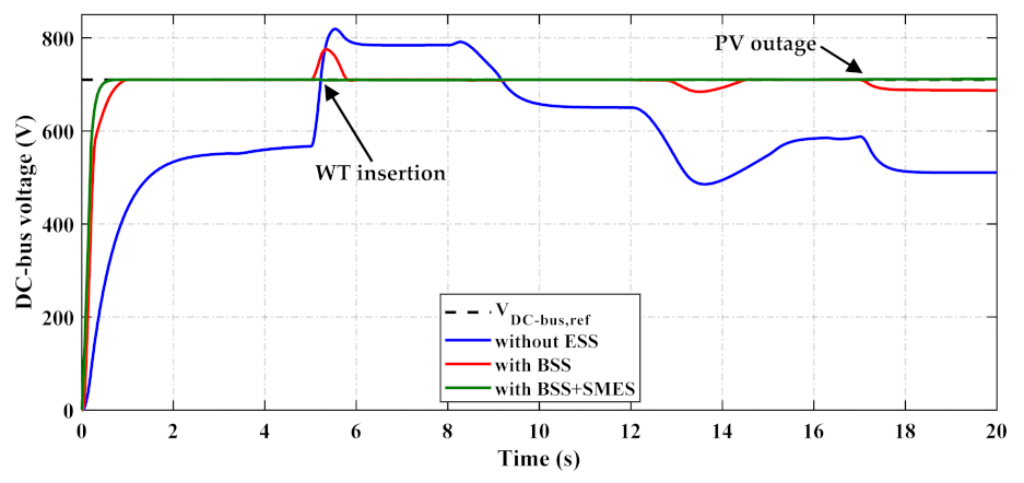
  • Mitigating the distinct instabilities of DC bus voltage and leveling the load power demand using the proposed control approach. The proposed control schemes for both battery and SMES offer simple implementation and high efficiency against the weather changes and RES insertion/outage.
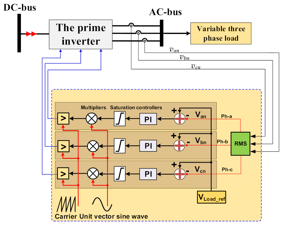
  • Keeping the load voltage/frequency steady using the proposed load controller is accomplished using the system inverter during weather changes and RES insertion/outage instants.
The remaining parts of the paper are as follows. Section 2 describes the overall system and its components and introduces the modeling scheme. Section 3 shows the overall proposed control method for each element in the studied system, while Section 4 presents the results and their discussion. Finally, conclusions are drawn in Section 5.

2. System and Methods

This study examined a network (Figure 2) which has a hybrid PV–wind power source combined with a hybrid BSS + SMES storage system. Each element of the system is discussed in detail below.

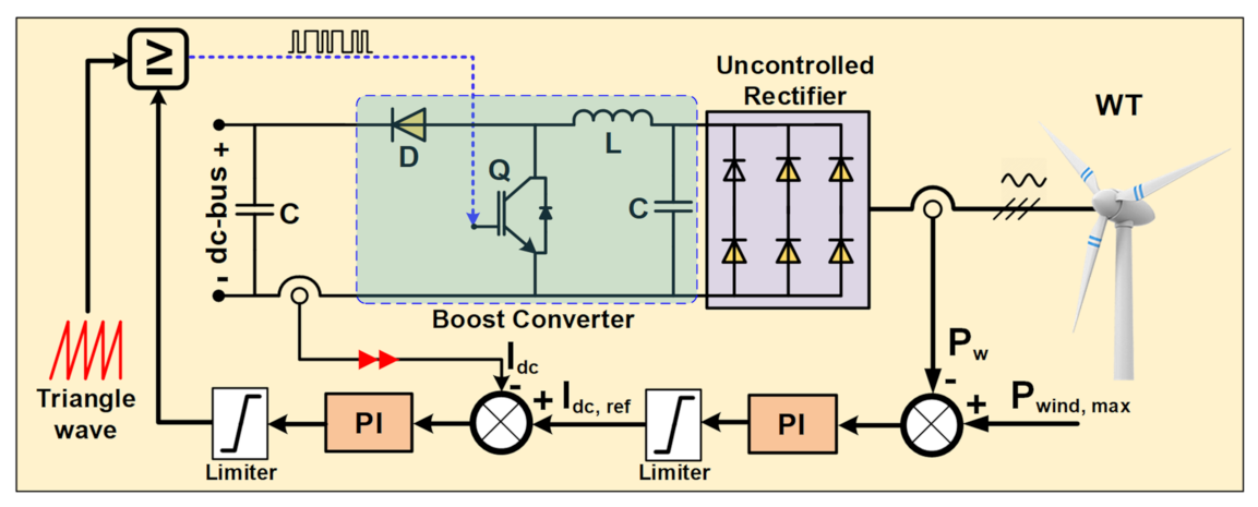
2.1. The Wind System

The wind system used in this study is based on PMSG. The output 3-phase voltage is converted to DC voltage by an uncontrolled rectifier, which is then controlled by a boost converter to hold the voltage at the DC bus voltage value. Additionally, the boost converter is used to obtain the maximum power from the wind-based PMSG at variable wind speeds. The different specifications of wind energy production are tabulated in Table 2.

2.2. The PV System

A PV system of 6.1 kW is employed in this system (Table 3); the PV array is linked with a boost converter to match its voltage with the voltage of the DC bus. Moreover, the boost converter performs the utilized MPPT based on the control method presented in Section 3.2.

2.3. Battery Energy Storage System (BSS)

The battery model implemented in the current study is based on the battery’s general model, which defines the state of charge (SoC) as a state variable to deal with the complex computation [31]. The battery is represented as a regulated voltage source based on a fixed resistance, as in Equations (1) and (2) [31].
E = E 0 P v C B S S C B S S 0 t i d t + A exp ( B 0 t i B S S d t )
V B S S = E R i . I B S S
In the previous equations, E is the battery open-circuit voltage, E0 is the battery fixed voltage, CBSS is the battery capacity, Pv is the polarization voltage value, x is the amplitude of the exponential zone, ∫ iBSS dt is the actual charge of the battery, y is the time constant inverse of the exponential zone, VBSS is the battery terminal voltage, iBSS is the battery current, and Ri is the internal resistance. The rated ampere hour (Ah) used in this study equaled 50 Ah, and a lead–acid battery was utilized in the hybrid DC microgrid. The battery’s capacity can be computed from Equation (3) [32], where (Ed/hr) is the energy supplied to the load during an hour, and (DoD) is the battery depth of discharge. The value of VBSS is set to 200 V while the DoD is set to 0.6.
C B S S = E d / h r V B S S * D o D

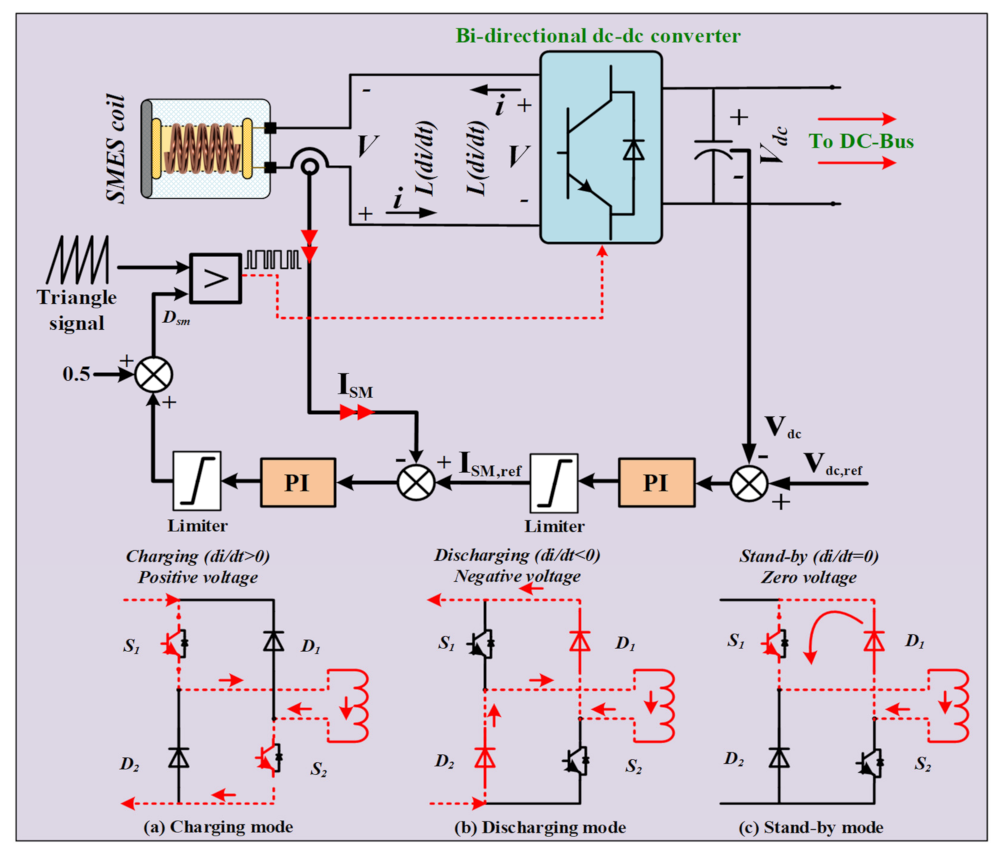
2.4. Superconducting Magnetic Energy Storage System (SMES)

The ESS concept converts the energy from electricity to a form based on the ESS type utilized. The SMES system stores the electrical energy in a magnetic field generated by a circulating current in the superconducting coil [33]. The main components of the SMES system are the superconducting coil, the cryogenic system, the power conversion–conditioning system (PCS), the protection system, and the control system [34]. The heart of the SMES system is the superconducting coil that is responsible for storing the energy. This coil is kept cold by the cryogenic refrigerator system to sustain the superconducting state in the wires. The PCS serves as a link between the stored energy and the AC in the power grid. Additionally, it regulates the charging/discharging of the SMES coil. Contrarily to other energy storage methods, the superconducting coil conducts the current in a unified way at all levels of operation. During the charging state, the PCS produces a +ve voltage across the SMES coil, which causes the current to rise. When the coil is in discharging mode, the PCS generates a −ve voltage, which causes the current to drop.
The protection system protects the SMES unit from unpredictable events. The control system connects power needs from/to the grid to/from the SMES unit [35]. Since the cooling system and coil material of SMES are still complex, the cost of SMES system installation is the highest compared to supercapacitors and batteries [36]. However, advanced research progress is currently addressing the development of high-temperature superconducting (HTS) materials [37] to reduce the cost of the SMES cooling system. Moreover, from the economic perspective, considering the economic information supplied in [38], the SMES has a reasonable cost compared to other ESSs. Moreover, the SMES has a favorable power density cost compared to other EESs. Similarly, the maintenance and operating costs of SMES systems are fairly low compared with different ESSs.
Since the service lifespan of the battery is restricted, relying on the intermittent behavior of RESs, a typical BSS in a typical microgrid may encounter various short-term charge and discharge cycles. Furthermore, the battery has a much lower power density than the SMES. The matter hinders the BSS from coping with high-frequency oscillations/instabilities. Since the SMES is distinguished by a superior power density and its ability to react to power needs quickly, it can play a vital role in the hybrid BSS + SMES system. In a hybrid BSS + SMES energy storage system, short-term high-frequency power oscillation is recognized and ingested by the SMES. Hence, batteries experience significantly fewer small-scale cycles than the individual utilization of BSS. In addition, in the individual utilization of BSS, the higher peak-to-peak current implies that the batteries experience more current with no contribution from additional energy storage devices such as the SMES. This, in turn, results in extending the battery lifespan and enhancing the efficiency of the whole system.
Table 4 summarizes the SMES unit parameters SMES power ( P s m ) and SMES energy ( E s m ), which are calculated by Equations (4) and (5), respectively, where V s m   is the SMES terminal voltage, I s m is the SMES current passed across the coil, and L s m is the SMES inductance.
P s m = V s m I s m
E s m = 1 2 L s m I s m 2

3. Control Approaches

The proposed control approach applied in this study plays a vital role in the performance of the studied system. The suggested control technique for each element is discussed in detail below.

3.1. Control of the Wind System

The wind system output power injected into the system at a no-load condition is presented in Equation (6) [39]. The value depends on the area swept by the rotor (A), air density (ρ), cubic wind speed (Vw3), and the wind power coefficient (Cp), which is computed by Equation (7) [32]. The coefficients from ca to cg are given in [39]. The wind speed signal performs a crucial role in designing the wind system MPPT. Cp is computed using Equations (7) and (8). The Cp depends on the blade pitch angle (β) and the tip-speed ratio (λ).
P W = 0.5   ρ A   V w 3 C p
C p ( λ , β ) = C a ( C b λ i C c β C d ) e C f λ i + C g λ
1 λ i = 1 λ + 0.08 β 0.035 β 3 + 1 , λ = R ω r V w
The (Cp) characteristics are presented in Figure 3, which describe the maximum value of λ, which is called the optimum tip-speed ratio (λopt). The maximum Cp, is called (Cpopt). Therefore, to maintain the value of λ at its optimum value, the generator speed must be set together with the variable wind speed. When the maximum value of the Cp is achieved, the maximum power from the wind system can be acquired (Pwmax). The MPPT of the wind system is illustrated in Figure 4, where the maximum reference power Pwmax is compared with the real generated power from the WT (Pw). The designed control system computes the boost converter duty cycle at different values of wind speeds.

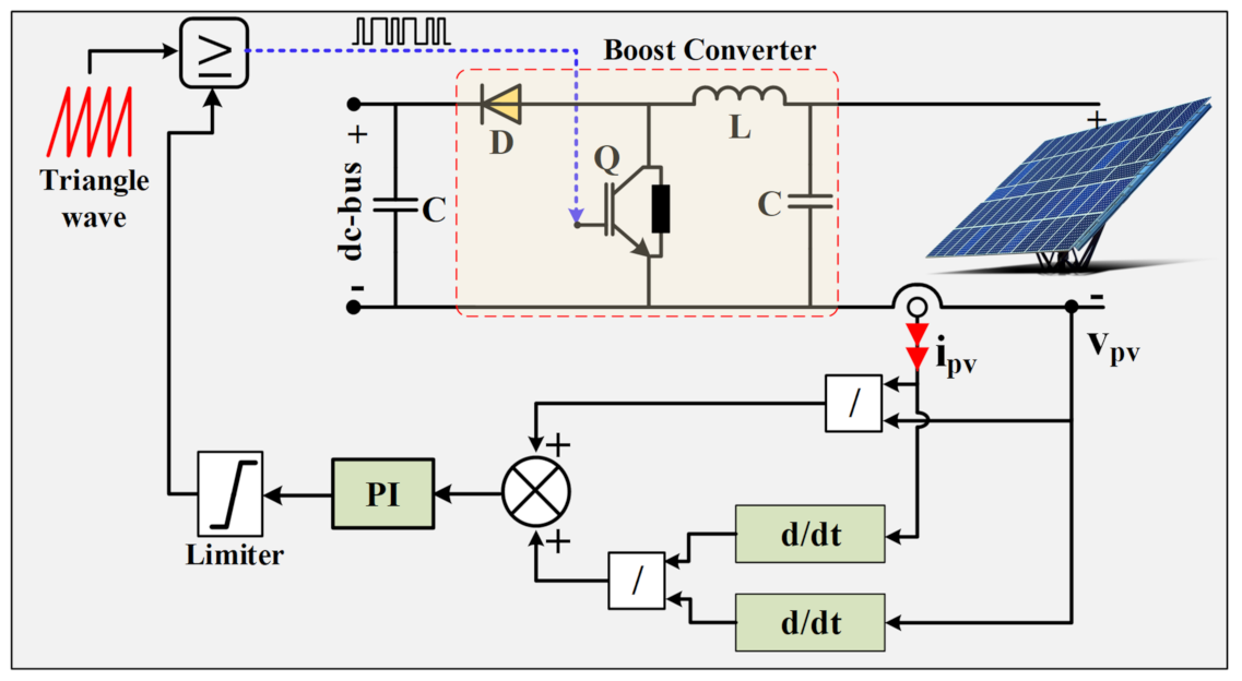
3.2. Control of the PV System

The interfaced converter boosts the voltage generated by the PV array to the inverter’s high DC bus voltage. The converter boosts the DC voltage of the array from 290 V to 1 kV by using the incremental conductance (INC) technique to adjust the switching duty cycle. The setpoint of the duty cycle is adjusted automatically by the MPPT-based INC technique to obtain the desired voltage and consequently achieve the main target that aims to obtain the maximum possible power from the solar PVs. The INC technique has a more significant performance in tracking the peak output of the PV module and in enhancing dynamic performance in quickly changing circumstances [40]. The voltage and current at the PV array terminals are measured first by the INC algorithm. After that, the INC technique produces the inductor current reference value that relies on the indications of variation in power and voltage compared to the previous step. At each step, the incremental value is used to define the new value of the inductor current reference, where it was chosen as a trade-off between the power oscillation and the speed of the MPPT. Equations (9) and (10) show the behavior and main idea of the INC technique operation by using the ideal P-V curve of a typical PV. If Equation (9) is achieved, the PV is operating at the highest point of the P-V curve, and consequently, the measured values of both voltage and current at the MPPT are recorded in Table 2.
Meanwhile, if Equation (3) is not achieved, the voltage and current values are far from the reference values. Hence, the incremental value driven by the controller is used to force the voltage and current value to follow the reference value in the direction of the P-V curve top point. So, the MPPT controller modifies the boost converter duty cycle to achieve the MPP operation from the PV system. The MPPT controller of the PV system applied in the current work is shown in the schematic diagram in Figure 5.
d P P V d V P V = 0 I P V + V P V d I P V d V P V = 0
d I P V d V P V = I P V V P V

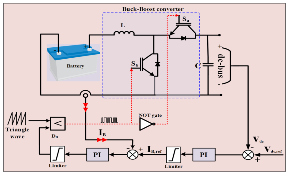
3.3. The Battery Control System

It is urgent to keep the voltage at the DC bus as steady as possible, because the load voltage follows all variations within the DC bus. Consequently, preserving the DC bus voltage at a constant value is necessary. The battery control system has a vital role in achieving this target; moreover, the battery can aid the power flow control in the system during abnormal conditions and variable generated power from the RESs. The difference between the actual value of the DC bus voltage and its reference value is used as an indicator for the battery operation and triggers the battery operation mode. When the produced power becomes higher than the load demand, the actual DC bus voltage value becomes higher than the reference value, and the battery operates in the charging mode through the duty cycle (DB) to reduce the gap between the reference and the DC bus voltage. Meanwhile, when the load power becomes higher than the generated power, the actual value of the DC bus voltage is lower than its reference value, the battery operates in the discharging mode and tries to reduce the DC bus voltage error. The whole battery control technique is displayed in Figure 6, where the battery’s actual current value is compared with the reference value generated from the previous control loop using PI controllers.

3.4. The SMES Control System

One of the most important parts of the SMES system is the bidirectional converter with a suitable controller. The primary function of the bidirectional converter applying a PI controller is to define the state of the SMES operation, as shown in Figure 6. The SMES has three modes of operation; the charging mode is achieved by applying a positive voltage across the SMES coil through firing the switches (S1 and S2), as shown in Figure 7a. Then, the duty cycle (Dsm) is more than 0.5 and less than 1.0. In this case, the power is provided from the grid to the SMES system. The discharging mode is achieved by applying a negative voltage within the coil of the SMES through D1 and D2, as shown in Figure 7b. The Dsm is less than 0.5 and more than zero; thus, the power is supplied from the SMES to the grid. The standby mode or the freewheeling mode is present when the values of S1 and D1 are 1 or the values of S2, and D2 are 1. In that case, the voltage across the coil is equal to zero, and there is no power transfer from the SMES system to the grid, as shown in Figure 7c where the Dsm equals 0.5. The discussed control method is performed through dual PI controllers, as presented in Figure 7. The first PI controller is used to minimize the error of the DC voltage; then, its output is used as a reference for the SMES current in the second PI controller. Finally, the Dsm is matched with the carrier signal to produce the corresponding firing angles for the converter switches.

3.5. The Inverter Control System

The three-phase inverter was used in this study to isolate the voltage and frequency of the load side far from the abnormal conditions, such as intermittent generation power from the RESs. Equation (11) is used to compute the load line voltages [41,42]. As shown by Equation (11), the DC bus voltage and the phase modulation index (mph,x; α refers to each of the phases) are used to regulate the voltages of the three-phase lines. Figure 8 indicates the overall control process of the three-phase inverter. The rms voltage value is compared with its reference value used to generate the mph,x. After that, the inverter switches are fired based on the mph,x to keep the load voltage as constant as possible, whatever the generation power is.
V L L = 0.6123   m p h , x   V D C b u s

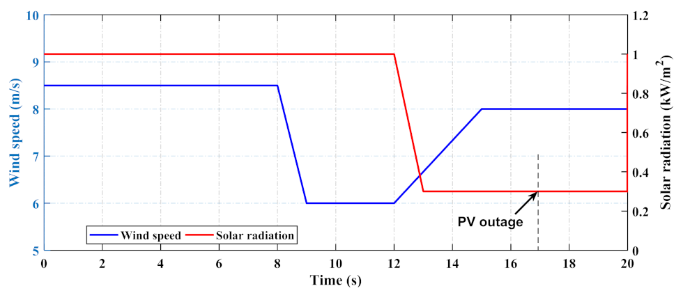
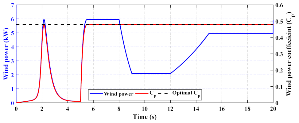
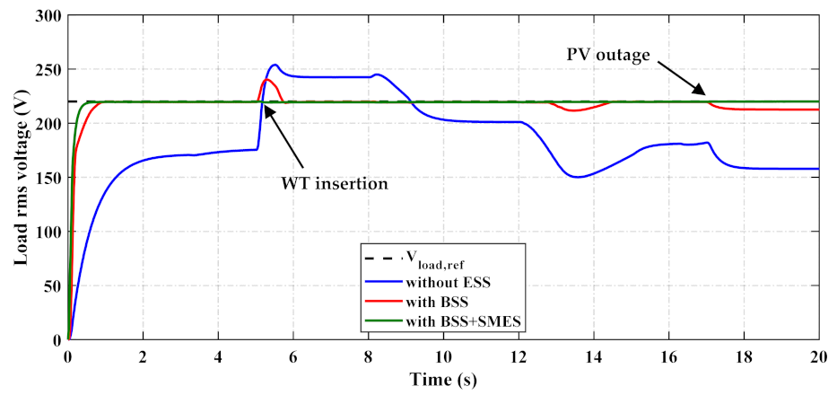
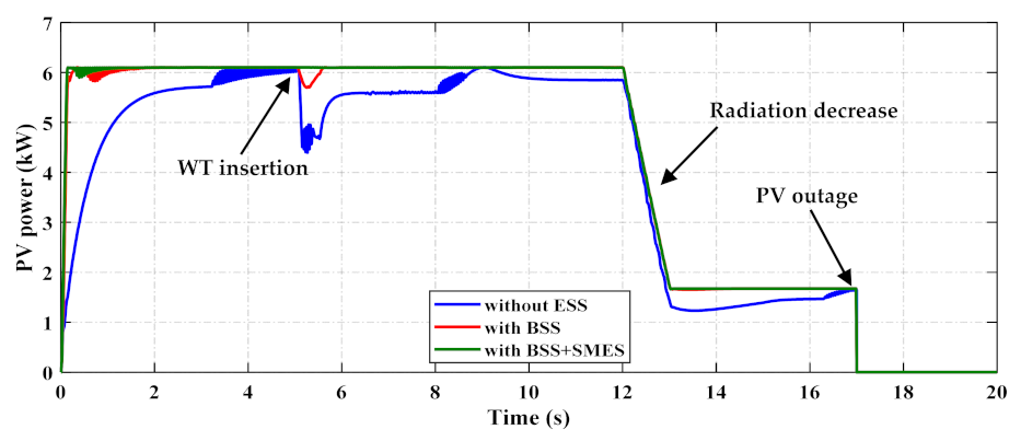
4. Results and Discussion

Since the primary aim of the current work is to evaluate the performance of the DC microgrid without ESS, with BSS only, and using hybrid BSS + SMES, different instabilities were examined in the system in the same simulation period. The wind energy system was considered disconnected from the MG system during the first five seconds to investigate the effectiveness of the hybrid BSS + SMES in alleviating the expected fluctuations from both the absence and connection of the wind energy system. Besides, wind speed and solar radiation variations were also addressed by simultaneously varying the wind speed and solar radiation profiles. Finally, the DC microgrid was also investigated under a PV outage, which could happen in a natural system through faults or due to by thick clouds. The main results that describe the microgrid system’s performance, including its distinct components, are presented below.
The system’s performance was analyzed by varying wind speed and solar irradiation, as displayed in Figure 9. The proposed MPPT control approaches to the wind system were effectively implemented throughout the wind speed deviations as indicated in Figure 10, where the wind power coefficient successfully tracked the optimal value despite the changes in wind speed. Besides, the MPPT approach of the PV system was efficiently implemented and shown in Figure 11; however, in the case of using only BSS, the PV power contained undershooting at the moment of connecting the WT. Meanwhile, when using the hybrid BSS + SMES, the PV power was smoothed out due to the swift response of the SMES system.
It can be seen from Figure 12 that the proposed BSS + SMES aided by the proposed control strategies successfully maintained the DC bus voltage throughout the examined variabilities. The figure shows that the suggested control techniques utilizing BSS + SMES are exceptional when contrasted with only BSS and without ESS. The enhancement of DC bus voltage is also displayed on the load rms voltage and load, as demonstrated in Figure 13 and Figure 14, respectively. The integration of the SMES efficiently smoothed out the load power compared to only using the battery. This is due to the efficient reply of the SMES in mitigating the instabilities significantly by a fast charge and discharge action. The behavior of the battery in terms of power, current, and SoC using only the battery and using the hybrid BSS + SMES can be seen in Figure 15, Figure 16 and Figure 17. It can be recognized that the battery performance changed with the inclusion of the SMES. The BSS stayed in the discharging mode for much longer in the presence of SMES, since the SMES started discharging at the instances of disturbances. The SMES behavior in terms of SMES current and energy is displayed in Figure 18, in which it can be recognized that the SMES remained in charging mode after the insertion of the WT. However, it started discharging after the outage of the PV system to aid the battery in supplying the load demand. The load voltage and frequency were also kept constant using both BSS only and BSS + SMES, but a superior performance was achieved with the integration of the hybrid ESS. This can be seen in Figure 19, Figure 20 and Figure 21, in which the instantaneous load voltage is displayed for the three examined cases. The hybrid BSS + SMES aided by the inverter control approach successfully upheld the load voltage and frequency compared to the battery only case.

5. Conclusions

The present study examined developed control methods for assessing the behavior of a solar PV-wind DC microgrid integrating (i) a battery storage system; or (ii) a hybrid energy storage comprising a battery and an SMES system through simulations. Comparisons were made for the baseline case, in which no ESS was applied. The developed work investigated controlling the active power in DC microgrids to regulate the voltage and power exchange. The PV, WT, BSS, or SMES were connected to the same DC bus, where a prime inverter converted the DC electricity to AC. The microgrid performance was compared in the three cases: without ESS, only BSS, and hybrid BSS + SMES systems.
Different mechanisms were offered; first, for obtaining the maximum possible power from the solar PV and the WT systems, MPPT control approaches were proposed. Second, the exchangeable power between the microgrid elements and the energy storage systems was controlled using the suggested control method of the bidirectional converters. The regulators were constructed to expedite the BSS and SMES systems to effectively charge and discharge power to compensate for the unpredictability of DC bus voltages during the examined instabilities. Third, the load voltage and frequency were kept steady using the proposed prime inverter, which continuously monitors the load voltages concerning the reference values.
The obtained results reveal the effectiveness of using the hybrid BSS + SMES over the BSS only during the examined instabilities. The hybrid BSS + SMES aided by the projected control approaches succeeded in lessening the DC bus and load voltages and augmenting the power conversation among the microgrid elements during the WT connection, the random variations of solar irradiance and wind speeds, and during the PV outage. The superior BSS + SMES transformed the control aims to immediately charge or discharge energy across the examined variations. This, in succession, assisted in enriching the DC bus and load voltages to acceptable limits, which justifies the significance of the proposed control approaches for the hybrid energy storage system. The outlook work is directed towards implementing a cooperative relationship between the battery and SMES systems through establishing an efficient, coordinated energy management system. This should assist in providing operating flexibility for both ESSs. Moreover, the hybrid ESS can be controlled using other advanced control techniques, such as fuzzy logic control, model predictive control, and AI-based methods.

Author Contributions

Conceptualization, H.S.S. and K.M.K.; methodology, H.S.S. and K.M.K.; software, K.M.K.; validation, H.S.S., I.V. and A.D.; formal analysis, H.S.S. and K.M.K.; investigation, H.S.S. and K.M.K.; resources, I.V. and A.D.; data curation, K.M.K.; writing—original draft preparation, H.S.S.; writing—review and editing, H.S.S. and K.M.K.; supervision, I.V. and A.D. All authors have read and agreed to the published version of the manuscript.

Funding

This research received no external funding.

Institutional Review Board Statement

Not applicable.

Informed Consent Statement

Not applicable.

Data Availability Statement

Not applicable.

Acknowledgments

The authors would like to thank M. F. Elmorshedy for his valuable cooperation over the course of the work. The researchers Hossam S. Salama and Kotb M. Kotb are funded by a scholarship under the joint executive program between the Arab Republic of Egypt and Hungary.

Conflicts of Interest

The authors declare no conflict of interest.

References

  1. Abdalla, A.N.; Nazir, M.S.; Tao, H.; Cao, S.; Ji, R.; Jiang, M.; Yao, L. Integration of energy storage system and renewable energy sources based on artificial intelligence: An overview. J. Energy Storage 2021, 40, 102811. [Google Scholar] [CrossRef]
  2. Al-Ismail, F.S. DC Microgrid Planning, Operation, and Control: A Comprehensive Review. IEEE Access 2021, 9, 36154–36172. [Google Scholar] [CrossRef]
  3. Chen, X.; Xiao, J.; Yuan, J.; Xiao, Z.; Gang, W. Application and performance analysis of 100% renewable energy systems serving low-density communities. Renew. Energy 2021, 176, 433–446. [Google Scholar] [CrossRef]
  4. Elmorshedy, M.F.; Elkadeem, M.R.; Kotb, K.M.; Taha, I.B.; Mazzeo, D. Optimal design and energy management of an isolated fully renewable energy system integrating batteries and supercapacitors. Energy Convers. Manag. 2021, 245, 114584. [Google Scholar] [CrossRef]
  5. IEA. Global Energy Review 2021. Available online: https://www.iea.org/reports/global-energy-review-2021 (accessed on 25 October 2021).
  6. Salama, H.S.; Vokony, I. Voltage and Frequency Control of Balanced/Unbalanced Distribution System Using the SMES System in the Presence of Wind Energy. Electricity 2021, 2, 205–224. [Google Scholar] [CrossRef]
  7. Salama, H.S.; Aly, M.M.; Abdel-Akher, M.; Vokony, I. Frequency and voltage control of Microgrid with high WECS penetration during wind gusts using superconducting magnetic energy storage. Electr. Eng. 2019, 1013, 771–786. [Google Scholar] [CrossRef]
  8. Koohi-Fayegh, S.; Rosen, M.A. A review of energy storage types, applications and recent developments. J. Energy Storage 2020, 27, 101047. [Google Scholar] [CrossRef]
  9. Salama, H.S.; Vokony, I. Comparison of different electric vehicle integration approaches in presence of photovoltaic and superconducting magnetic energy storage systems. J. Clean. Prod. 2020, 260, 121099. [Google Scholar] [CrossRef]
  10. Salama, H.S.; Vokony, I. Application of controlled SMES with Integrating PV System and Electric Vehicles into Power System. In Proceedings of the 2019 7th International Youth Conference on Energy (IYCE), Bled, Slovenia, 3–6 July 2019. [Google Scholar] [CrossRef]
  11. Elmorshedy, M.F.; Kotb, K.M.; Dan, A. Hybrid Renewable Microgrid System Based DC-bus Scheme for Residential Load Applications. In Proceedings of the 2019 22nd International Conference on Electrical Machines and Systems (ICEMS), Harbin, China, 11–14 August 2019. [Google Scholar] [CrossRef]
  12. Juma, M.I.; Mwinyiwiwa, B.M.M.; Msigwa, C.J.; Mushi, A.T. Design of a Hybrid Energy System with Energy Storage for Standalone DC Microgrid Application. Energies 2021, 14, 5994. [Google Scholar] [CrossRef]
  13. Sitompul, S.; Fujita, G. Impact of Advanced Load-Frequency Control on Optimal Size of Battery Energy Storage in Islanded Microgrid System. Energies 2021, 14, 2213. [Google Scholar] [CrossRef]
  14. Sitompul, S.; Hanawa, Y.; Bupphaves, V.; Fujita, G. State of Charge Control Integrated with Load Frequency Control for BESS in Islanded Microgrid. Energies 2020, 13, 4657. [Google Scholar] [CrossRef]
  15. Alam, M.S.; Al-Ismail, F.S.; Abido, M.A. PV/Wind-Integrated Low-Inertia System Frequency Control: PSO-Optimized Fractional-Order PI-Based SMES Approach. Sustainability 2021, 13, 7622. [Google Scholar] [CrossRef]
  16. Alattar, A.H.; Selem, S.I.; Metwally, H.; Ibrahim, A.; Aboelsaud, R.; Tolba, M.A.; El-Rifaie, A.M. Performance enhancement of micro grid system with SMES storage system based on mine blast optimization algorithm. Energies 2019, 12, 3110. [Google Scholar] [CrossRef] [Green Version]
  17. Gu, W.; Liu, W.; Wu, Z.; Zhao, B.; Chen, W. Cooperative control to enhance the frequency stability of islanded microgrids with DFIG-SMES. Energies 2013, 6, 3951–3971. [Google Scholar] [CrossRef]
  18. Magdy, G.; Bakeer, A.; Nour, M.; Petlenkov, E. A New Virtual Synchronous Generator Design Based on the SMES System for Frequency Stability of Low-Inertia Power Grids. Energies 2020, 13, 5641. [Google Scholar] [CrossRef]
  19. Chen, L.; Chen, H.; Li, Y.; Li, G.; Yang, J.; Liu, X.; Xu, Y.; Ren, L.; Tang, Y. SMES-Battery Energy Storage System for the Stabilization of a Photovoltaic-Based Microgrid. IEEE Trans. Appl. Supercond. 2018, 28, 1–7. [Google Scholar] [CrossRef]
  20. Salama, H.S.; Said, S.M.; Aly, M.; Vokony, I.; Hartmann, B. Studying impacts of electric vehicle functionalities in wind energy-powered utility grids with energy storage device. IEEE Access 2021, 9, 45754–45769. [Google Scholar] [CrossRef]
  21. Omran, K.C.; Mosallanejad, A. SMES/battery hybrid energy storage system based on bidirectional Z-source inverter for electric vehicles. IET Electr. Syst. Transp. 2018, 8, 215–220. [Google Scholar] [CrossRef]
  22. Bakeer, A.; Salama, H.S.; Vokony, I. Integration of PV system with SMES based on model predictive control for utility grid reliability improvement. Prot. Control Mod. Power Syst. 2021, 6, 1–13. [Google Scholar] [CrossRef]
  23. Yang, B.; Zhu, T.; Zhang, X.; Wang, J.; Shu, H.; Li, S.; He, T.; Yang, L.; Yu, T. Design and implementation of Battery/SMES hybrid energy storage systems used in electric vehicles: A nonlinear robust fractional-order control approach. Energy 2020, 191, 116510. [Google Scholar] [CrossRef]
  24. Shim, J.W.; Cho, Y.; Kim, S.J.; Min, S.W.; Hur, K. Synergistic control of SMES and battery energy storage for enabling dispatchability of renewable energy sources. IEEE Trans. Appl. Supercond. 2013, 23, 5701205. [Google Scholar] [CrossRef]
  25. Elmorshedy, M.; Amin, M.M.; El-Sousy, F.F.; Mohammed, O.A. DC-Bus Voltage Control of MPPT-based Wind Generation System Using Hybrid BESS-SMES System for Pulse Loads in Ship Power Applications. In Proceedings of the 2021 IEEE Applied Power Electronics Conference and Exposition (APEC), Phoenix, AZ, USA, 14–17 June 2021; pp. 76–82. [Google Scholar] [CrossRef]
  26. Jin, J.X.; Wang, J.; Yang, R.H.; Zhang, T.L.; Mu, S.; Fan, Y.J.; Xing, Y.Q. A superconducting magnetic energy storage with dual functions of active filtering and power fluctuation suppression for photovoltaic microgrid. J. Energy Storage 2021, 38, 102508. [Google Scholar] [CrossRef]
  27. Chen, L.; Zhang, X.; Han, P.; Chen, H.; Xu, Y.; Ren, L.; Tang, Y. Optimization of SMES-Battery Hybrid Energy Storage System for Wind Power Smoothing. In Proceedings of the 2020 IEEE International Conference on Applied Superconductivity and Electromagnetic Devices (ASEMD), Tianjin, China, 16–18 October 2020; pp. 1–2. [Google Scholar] [CrossRef]
  28. Rajapakse, G.; Jayasinghe, S.; Fleming, A. Power Management of an Oscillating Water Column Wave Energy Converter with Battery/Supercapacitor Hybrid Energy Storage. In Proceedings of the 2018 8th International Conference on Power and Energy Systems (ICPES), Colombo, Sri Lanka, 21–22 December 2018; pp. 246–251. [Google Scholar] [CrossRef]
  29. Rout, T.; Maharana, M.K.; Chowdhury, A.; Samal, S. A Comparative study of Stand-alone Photo-Voltaic System with Battery storage system and Battery Supercapacitor storage system. In Proceedings of the 2018 4th International Conference on Electrical Energy Systems (ICEES), Chennai, India, 7–9 February 2018; pp. 77–81. [Google Scholar] [CrossRef]
  30. Wongdet, P.; Marungsri, B. Hybrid Energy Storage System in Standalone DC Microgrid with Ramp Rate Limitation for Extending the Lifespan of Battery. In Proceedings of the 2018 International Electrical Engineering Congress (iEECON), Krabi, Thailand, 7–9 March 2018; pp. 1–4. [Google Scholar] [CrossRef]
  31. Tremblay, O.; Dessaint, L.A.; Dekkiche, A.I. A generic battery model for the dynamic simulation of hybrid electric vehicles. In Proceedings of the VPPC 2007—2007 IEEE Vehicle Power and Propulsion Conference, Arlington, TX, USA, 9–12 September 2007; pp. 284–289. [Google Scholar] [CrossRef]
  32. Allam, S.M.; Elmorshedy, M.F.; Rashad, E.M. Load Power and State-of-Charge Management Strategy with MPPT of Wind-Driven Isolated PMSG. In Proceedings of the 22nd International Conference on Electrical Machines (ICEM), Lausanne, Switzerland, 4–7 September 2016; pp. 1098–1104. [Google Scholar]
  33. Salama, H.S.; Abdel-Akher, M.; Aly, M.M. Development energy management strategy of SMES-based Microgrid for stable islanding transition. In Proceedings of the 2016 Eighteenth International Middle East Power Systems Conference (MEPCON), Cairo, Egypt, 27–29 December 2016; pp. 413–418. [Google Scholar] [CrossRef]
  34. Salama, H.S.; Vokony, I. Power Stability Enhancement of SCIG and DFIG Based Wind Turbine Using Controlled-SMES. Int. J. Renew. Energy Res. 2019, 9, 147–156. [Google Scholar]
  35. Yang, Y.; Wei, B.; Chen, P.; Zhang, H.; Qiu, M.; Zhang, D. The quench protection system for superconducting magnetic energy storage. IEEE Trans. Appl. Supercond. 2012, 23, 4700704. [Google Scholar] [CrossRef]
  36. Faisal, M.; Hannan, M.A.; Ker, P.J.; Hussain, A.; Mansor, M.B.; Blaabjerg, F. Review of energy storage system technologies in microgrid applications: Issues and challenges. IEEE Access 2018, 6, 35143–35164. [Google Scholar] [CrossRef]
  37. Melhem, Z. (Ed.) High Temperature Superconductors (HTS) for Energy Applications; Elsevier: Amsterdam, The Netherlands, 2011. [Google Scholar]
  38. Johnson, S.C.; Davidson, F.T.; Rhodes, J.D.; Coleman, J.L.; Bragg-Sitton, S.M.; Dufek, E.J.; Webber, M.E. Selecting favorable energy storage technologies for nuclear power. In Storage and Hybridization of Nuclear Energy; Academic Press: Cambridge, MA, USA, 2019; pp. 119–175. [Google Scholar]
  39. Kotb, K.M.; Elkadeem, M.R.; Elmorshedy, M.F.; Dán, A. Coordinated power management and optimized techno-enviro-economic design of an autonomous hybrid renewable microgrid: A case study in Egypt. Energy Convers. Manag. 2020, 221, 113185. [Google Scholar] [CrossRef]
  40. Liu, F.; Duan, S.; Liu, F.; Liu, B.; Kang, Y. A variable step size INC MPPT method for PV systems. IEEE Trans. Ind. Electron. 2008, 55, 2622–2628. [Google Scholar] [CrossRef] [Green Version]
  41. Kotb, K.M.; Elmorshedy, M.F.; Dán, A. Performance Assessment of Integrating SMES and Battery Storage Systems with Renewable DC-bus Microgrids: A Comparison. Period. Polytech. Electr. Eng. Comput. Sci. 2021, 65, 382–393. [Google Scholar] [CrossRef]
  42. Kotb, K.M.; Elmorshedy, M.F.; Salama, H.S.; Dán, A. Enriching the stability of solar/wind DC microgrids using battery and superconducting magnetic energy storage based fuzzy logic control. J. Energy Storag. 2022, 45, 103751. [Google Scholar] [CrossRef]
Figure 1. RESs’ production growth by (a) RESs types and country in 2020–2021, and (b) types in 2019–2020 and 2020–2021 [5].
Eng 03 00016 g001aEng 03 00016 g001b
Figure 2. Schematic diagram of the whole system with the proposed controllers.
Eng 03 00016 g002
Figure 3. The relation between Cp and λ at distinct values of blade pitch angles (β).
Eng 03 00016 g003
Figure 4. MPPT of the wind system.
Eng 03 00016 g004
Figure 5. MPPT control of the PV system.
Eng 03 00016 g005
Figure 6. The battery control system.
Eng 03 00016 g006
Figure 7. The SMES control modes: (a) charging mode, (b) discharging mode, and (c) stand-by mode.
Eng 03 00016 g007
Figure 8. The prime inverter control system.
Eng 03 00016 g008
Figure 9. Wind speed and solar irradiation profiles.
Eng 03 00016 g009
Figure 10. Wind power and its coefficient confirms the effectiveness of the WT-MPPT.
Eng 03 00016 g010
Figure 11. PV power during the three examined cases.
Eng 03 00016 g011
Figure 12. DC bus voltage during the three examined cases.
Eng 03 00016 g012
Figure 13. Load rms voltage during the three examined cases.
Eng 03 00016 g013
Figure 14. Load power during the three examined cases.
Eng 03 00016 g014
Figure 15. The battery power using battery only and using BSS + SMES.
Eng 03 00016 g015
Figure 16. Battery current and SoC using battery only.
Eng 03 00016 g016
Figure 17. Battery current and SoC using BSS + SMES.
Eng 03 00016 g017
Figure 18. SMES current and energy using BSS + SMES.
Eng 03 00016 g018
Figure 19. Load instantaneous voltage without using ESS.
Eng 03 00016 g019
Figure 20. Load instantaneous voltage using BSS only.
Eng 03 00016 g020
Figure 21. Load instantaneous voltage using BSS + SMES.
Eng 03 00016 g021
Table 1. Comparison of the most featured studies in the literature with the current study.
Ref.Utilized RESsBUS TypeGrid-Utilized Hybrid ESSESS ControllerCase Studies
PVWTOnOff
[25]-DC-Battery + SMESPIVariable wind speed
[26]-AC-Battery + SMESPI + FLCLoad change
[27]-AC-Battery + SMESPIVariable wind speed
[28]-DC-Battery + SupercapacitorPIVariable wind speed
[29]-DC-Battery + SupercapacitorRule-Based Controller (RBC)Variable solar irradiation and load change
[30]DC-Battery + SupercapacitorRamp Rate Limitation (RRL)Load change
Current studyDC-Battery + SMESPIPV outage, WT insertion, variable solar radiation and wind speed
Table 2. Specifications of the wind energy production system.
The WTThe PMSG
ParameterValueParameterValue
Rated power7 kWRated power6.1 kW
Blades radius3.2 mRated torque40 N m
Cut-in wind speed4 m/sRated speed153 rad/s
Cut-out wind speed12 m/sRated current12 A
Friction coefficient0.06 N m s/radResistance of armature0.4 Ω
Inertia7.5 kg m2Inductance of stator8.4 mH
Table 3. The PV system parameters.
ParameterValue
Open-circuit voltage321 V
Short-circuit current18.4 A
Max. power point voltage Vmp273.5 V
Max. power point current Imp22.32 A
Parallel strings4
Series modules/string5
Table 4. The SMES system parameters.
ParameterValue
Esm120 kJ
Lsm2 H
Ism350 A
Publisher’s Note: MDPI stays neutral with regard to jurisdictional claims in published maps and institutional affiliations.

