1. Introduction
The rapid evolution of additive manufacturing in the construction industry has introduced a transformative technique known as 3DCP [
1]. This layer-by-layer construction method offers advantages such as reduced material waste, formwork-free fabrication, accelerated construction times, and architectural flexibility [
2,
3,
4]. Despite its growing use in infrastructure and architectural projects, questions remain about the long-term performance of 3DPC, especially under environmental conditions like freeze–thaw cycles. Freeze–thaw resistance is a critical criterion for concrete durability in regions exposed to cyclic freezing and thawing, which is especially damaging due to the expansive pressure caused by water freezing within pores [
5,
6,
7,
8]. The deterioration appears as microcracking, surface scaling, and the eventual loss of mechanical integrity [
9,
10,
11]. Traditional cast concrete generally benefits from internal vibrations during casting, leading to a relatively dense and homogeneous matrix with fewer weak planes [
12]. In contrast, 3D-printed concrete lacks vibration and is formed through sequential filament deposition, resulting in anisotropic structures with pronounced interfacial zones between layers. These features introduce additional vulnerabilities under F–T conditions, such as increased porosity, weak bonding, and directional cracking tendencies. In 3DPC, the absence of vibration during placement, and the anisotropic nature of layer interfaces introduce additional vulnerabilities, particularly at the interfacial zones [
13,
14]. Such distinct differences between traditional and 3DPC necessitate a differentiated understanding of the mechanisms of F–T degradation and the corresponding mitigation strategies. These special features make 3DPC different from regular concrete and require specific studies on how it handles freeze–thaw conditions.
Understanding the mechanisms of ice formation in concrete pores is fundamental to evaluating F–T durability, especially in hydraulic structures exposed to harsh environments. Cai and Liu [
15] demonstrated that most frost damage in ordinary concrete occurs between 0 °C and −10 °C due to the rapid freezing of the pore solution, which generates significant internal hydraulic pressure. Their study used electrical conductivity measurements to monitor the freezing process and revealed that further ice formation below −10 °C, although present, contributes negligibly to damage in conventional concrete. This insight highlights the critical importance of pore size distribution and freezing kinetics in assessing frost resistance, particularly for optimizing the performance of 3DPC with varied microstructural characteristics.
The F–T durability of concrete is closely influenced by the properties of its constituent materials, particularly aggregate porosity and the water-to-cement ratio. Bogas et al. [
16] investigated the performance of concrete by incorporating fine recycled concrete aggregates (FRCA) under 300 F–T cycles, revealing that while normal-strength concrete suffered significant deterioration, high-strength mixes maintained good durability. The study highlighted that FRCA did not inherently reduce internal F–T resistance; instead, surface scaling was more severe due to weaker recycled mortar. Interestingly, the high permeability of FRCA may aid in dissipating internal pressures during freezing, which suggests potential parallels for 3DPC systems utilizing porous or recycled aggregates.
The F–T durability of Ultra-High Performance Concrete (UHPC) is highly sensitive to its mix composition, particularly the water-to-binder ratio. Lu et al. [
17] demonstrated that a lower water-to-binder ratio significantly enhances freeze–thaw resistance by reducing average pore size and cumulative pore volume, thereby limiting internal stresses during freezing cycles. Moreover, the addition of steel fibers, silica fume, and fly ash at optimal dosages further improved performance by refining pore structure and enhancing matrix densification. Their study utilized scanning electron microscopy (SEM) and mercury intrusion porosimetry (MIP) to reveal the microstructural mechanisms and employed grey correlation entropy analysis to quantify the relative influence of each component, identifying the water–binder ratio as the most critical factor affecting F–T resistance.
In a recent study, He and Lu [
18] explored the incorporation of thermo-expansive polymeric microspheres as an alternative to conventional air-entraining agents (AEA) to enhance the F–T durability of concrete. Their findings revealed that polymeric microspheres entrained a finer and more uniformly distributed air void system, leading to improved dynamic modulus retention and significantly reduced surface scaling under F–T cycles. Unlike AEA, which often compromises compressive strength, the microsphere-modified concretes exhibited slightly enhanced strength due to internal curing and nucleation effects. These results highlight the potential of polymeric microspheres in achieving robust freeze–thaw resistance while mitigating the common drawbacks associated with traditional AEAs.
Recent advancements have also explored the role of nanomaterials in enhancing the durability of 3DPC. Bradshaw et al. [
19] highlighted that the inclusion of nano-silica and other nano-modifiers can significantly reduce interlayer porosity and refine the microstructure, thereby improving resistance to aggressive agents such as chlorides and sulfates. For instance, a combination of metakaolin and 1% nano-silica resulted in a 56.9% reduction in porosity compared to control mixes, directly enhancing the long-term durability of 3DPC structures.
Several recent studies have sought to characterize and improve the F–T durability of 3DPC. GivKashi and Tohidloo [
20] studied air-entrained 3DPC under freeze–thaw cycles and found that the small air bubbles created by air-entraining agents (AEAs) helped reduce internal stress. As a result, the compressive strength of the air-entrained samples dropped 1.4–5.3% less than that of the control samples. Similarly, Tarhan and Şahin [
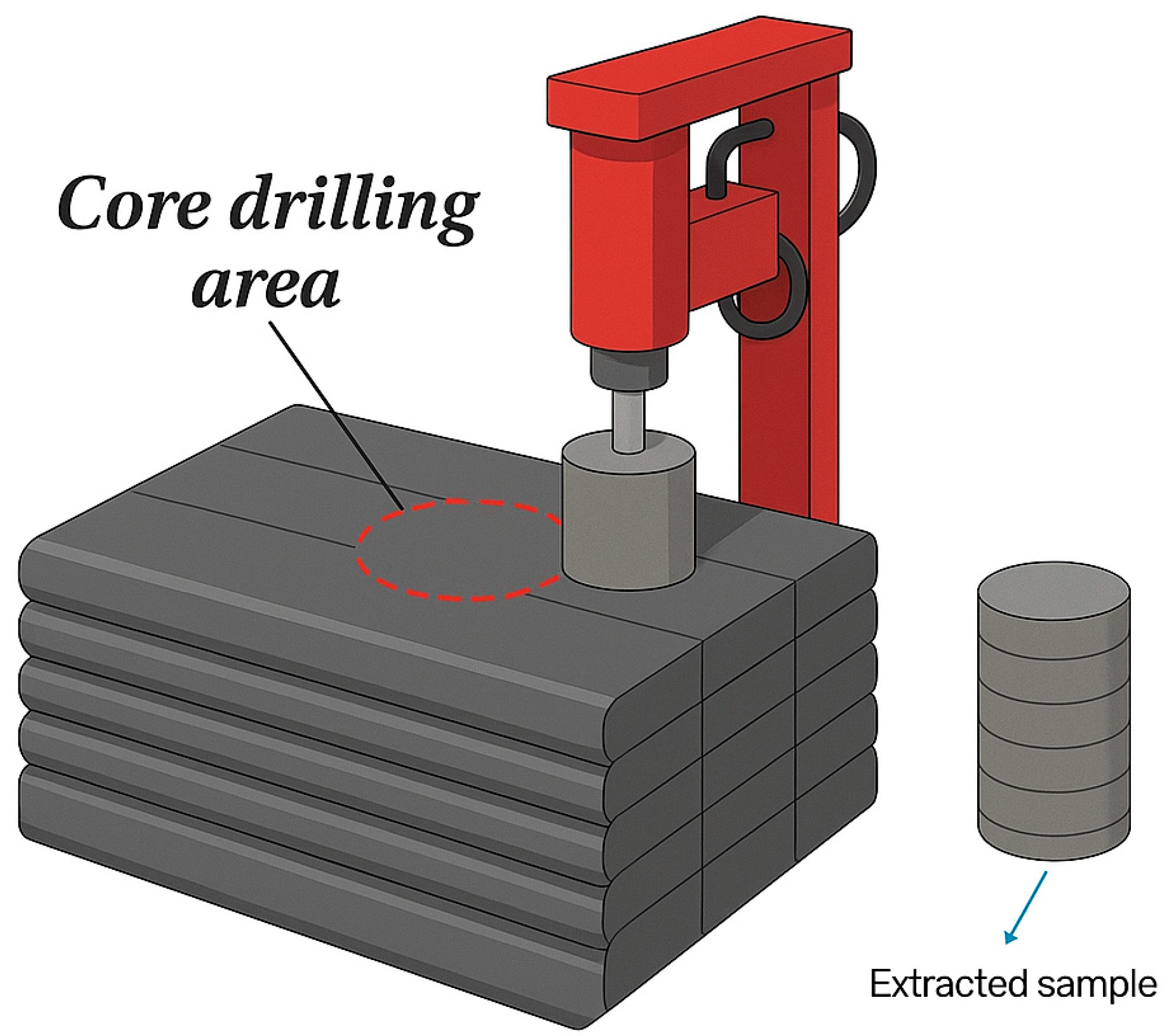
21] analyzed core specimens from different print orientations and concluded that horizontally cored samples with 0.1% AEA exhibited a 15% increase in dynamic modulus of elasticity compared to control samples and survived up to 300 F–T cycles without notable degradation. A schematic of horizontal and vertical cored samples is shown in
Figure 1.
The microstructural implications of these additives and process parameters were further explored using imaging techniques like X-ray computed tomography and scanning electron microscopy. Liu et al. [
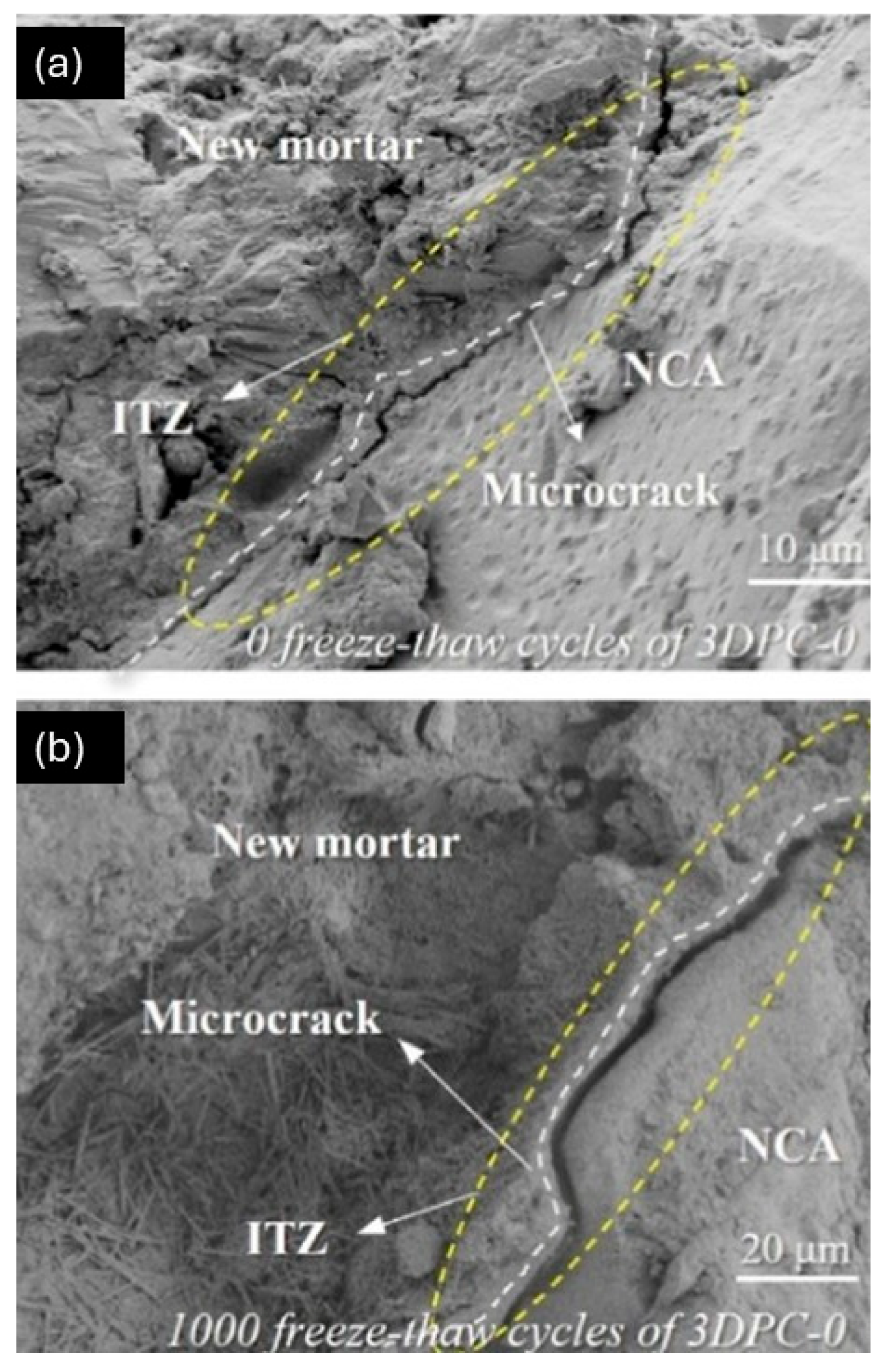
22] employed these tools to correlate the pore structure in 3D-printed recycled aggregate concrete with mass loss and dynamic modulus of elasticity decline under F–T cycles, revealing that ellipsoidal pores and porous interfacial transition zones (ITZ) worsened degradation. Wang et al. [
23] confirmed that 3DPC had fewer large pores compared to cast concrete, showing that the extrusion and layering process made the concrete more compact; however, it had more total pores overall, meaning it contained more small pores than cast concrete. Also, the inter-filaments (vertical direction) were more likely to be damaged by freeze–thaw cycles than the inter-layers (horizontal direction), and both were more affected than regular cast concrete.
Furthermore, the orientation of printing layers has emerged as a key factor affecting F–T resistance. The anisotropic nature of layer interfaces often causes preferential crack development. Assaad et al. [
24] demonstrated that polymer modification, particularly with styrene-butadiene rubber (SBR), can outperform traditional AEAs by enhancing flexibility and accommodating interface deformations during F–T cycles. This highlights the potential for hybrid admixture systems to address both interfacial and matrix vulnerabilities.
Additionally, the integration of locally sourced alternative materials like aeolian sand and recycled aggregates has been explored for sustainable 3DPC production. Dong et al. [
25] and Wang et al. [
26] showed that such materials, when properly proportioned, can maintain acceptable mechanical and F–T resistance, though the porosity and strength loss generally increase with F–T cycling. Muy et al. [
27] emphasized that even after 91 cycles, 3DPC with 100% recycled fine aggregates exhibited minimal spalling, suggesting its potential for urban applications with moderate environmental exposure. Moreover, the use of advanced nanomaterials has introduced new opportunities for enhancing durability. Tanyildizi et al. [
28] demonstrated that the inclusion of 0.5% nano-zinc oxide in geopolymer-based 3DPC significantly increased F–T resistance, with compressive strength retention rates exceeding 95%.
Although advancements in material science and processing techniques have yielded encouraging results, there is no standard test system to evaluate the freeze–thaw degradation behavior of 3DPC in different construction orientations. Existing standards for conventional concrete fail to capture the anisotropic and layer-dependent responses of printed structures. Furthermore, variability in testing procedures, such as cycle duration, saturation conditions, and orientation of specimens, and even the type of testing complicates cross-study comparisons.
This review aims to systematically examine the state-of-the-art understanding of freeze–thaw performance in 3D-printed concrete, highlight the governing mechanisms of degradation, evaluate current mitigation strategies, and identify knowledge gaps. The goal is to provide insights that inform durable mix designs and processing techniques for 3DPC in cold regions, thereby promoting its wider adoption in structural and non-structural applications.
2. Overview of Freeze–Thaw Mechanism in Concrete
Concrete in cold climates is highly susceptible to deterioration from freeze–thaw cycles. This degradation stems from the freezing of pore water, which expands by approximately 9% in volume, exerting internal stresses that lead to microcracking, delamination, and eventual surface scaling [
29]. The process is particularly damaging when the concrete’s pores are nearly saturated, as even minor temperature drops can result in critical stress accumulation.
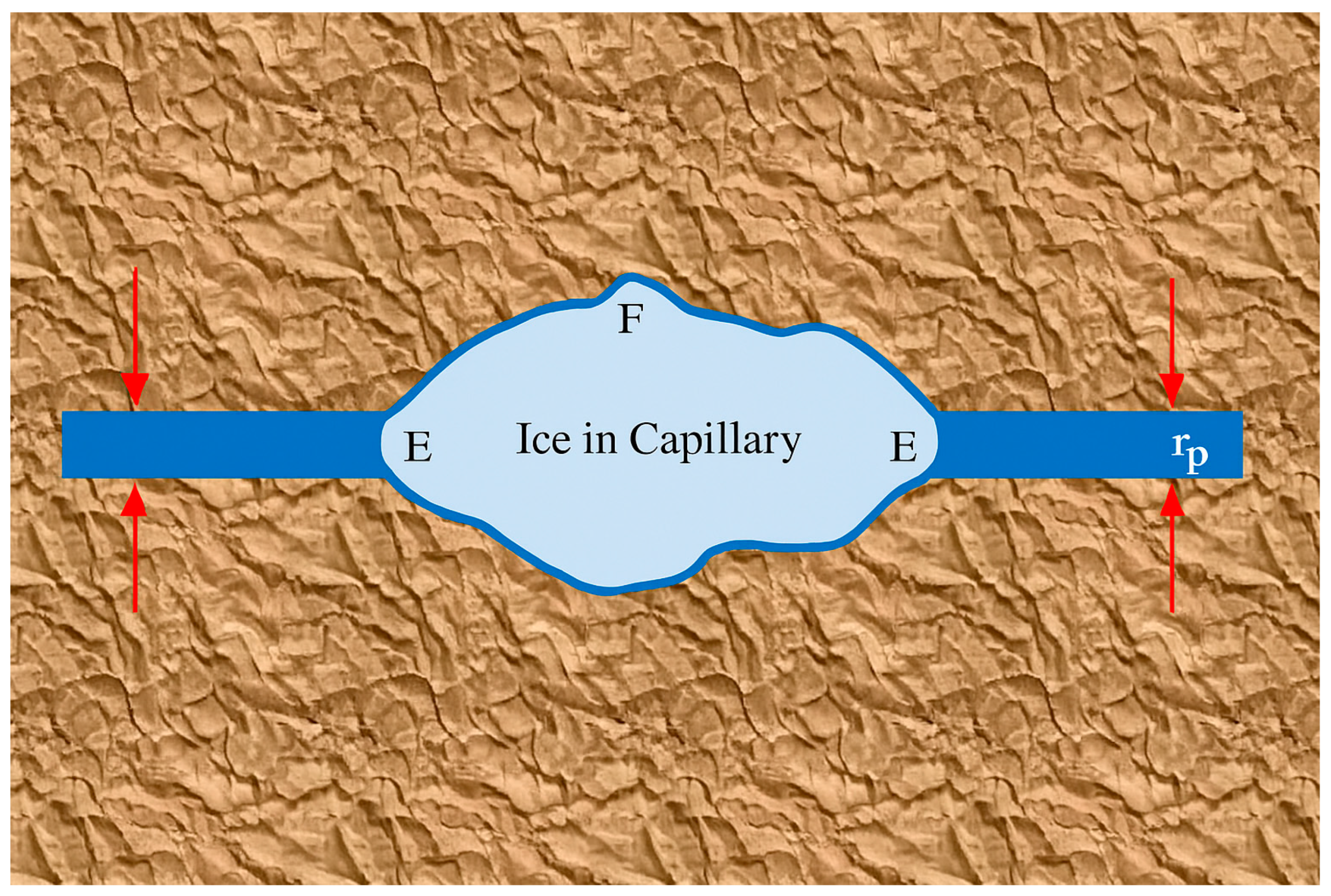
Figure 2 shows a schematic of ice forming in a capillary cavity [
30]. Furthermore, Luo et al. [
31] highlighted that the presence of salts exacerbates F–T damage due to salt-induced osmotic gradients and crystallization pressure. The combination of freezing water and crystallizing salt particles accelerates matrix degradation, especially near the surface. Two prevailing theories explain the internal mechanisms of F–T damage: the critical saturation theory and the pressure release void theory. The critical saturation theory posits that concrete begins to experience F–T damage when its degree of saturation exceeds a critical threshold (typically around 85–91%) [
32,
33,
34]; beyond this level, the pressure generated by ice formation within the pores cannot be accommodated, leading to cracking. The pressure release void theory, on the other hand, suggests that entrained air voids in the concrete act as safety reservoirs. These microscopic voids allow expanding ice and water to enter during freezing, thereby mitigating internal stresses and preventing microstructural damage [
35]. Both theories remain applicable to 3DPC but require adjustment due to its unique microstructure. The lack of vibration during 3D printing typically results in higher porosity and non-uniform pore distribution, which may affect the critical saturation level. Additionally, the anisotropic layer-by-layer deposition and weak interfacial zones in 3DPC reduce the efficiency of pressure relief mechanisms; therefore, the effectiveness of air-entraining admixtures in 3DPC relies not only on void distribution but also on void connectivity and placement relative to interlayer interfaces. These factors complicate the direct application of traditional theories and necessitate further investigation tailored to 3DPC systems. In 3DPC, these effects are amplified due to its distinct microstructure. Hassan Khan et al. [
36] concluded that poor interlayer bonding significantly reduces freeze–thaw resilience in 3DPC specimens. The layer-by-layer deposition method introduces anisotropic bonding interfaces and increased porosity compared to cast concrete [
37]. These mechanisms are further explained by Liu et al. [
22], who identified interfacial pore concentration as a key degradation driver. Similarly, Wang et al. [
4] and Wang et al. [
26] observed that the orientation of print layers significantly influences degradation, with vertical planes (PS-Y direction) experiencing higher porosity increases and faster modulus loss. The incorporation of air-entraining agents remains one of the most effective methods to mitigate F–T damage [
38]. These agents introduce microscopic air voids that act as pressure-relief zones, absorbing the expansion of freezing water [
39]. GivKashi et al. [
20] reported that AEAs reduced strength loss by up to 5.3% in 3DPC after F–T exposure, while Tarhan and Şahin [
21] found a 15% improvement in dynamic modulus for horizontally cored 3DPC with 0.1% AEA. Recent studies have highlighted that beyond conventional air-entraining techniques, nanomaterials like nano-silica (NS) and colloidal nano-silica (CNS) play a promising role in mitigating freeze–thaw damage. According to Huang et al. [
40], the incorporation of CNS into concrete not only enhances the air void system by stabilizing smaller bubbles but also densifies the matrix by refining pore structure. The increased air void content coupled with smaller average void size effectively dissipates internal pressure during freezing.
Despite these improvements, the combination of poor interlayer bonding, heterogeneity, and directional weaknesses in 3DPC calls for more targeted durability strategies [
41]. Conventional models like hydraulic and osmotic pressure theories still explain most of the observed damage mechanisms, but additional care is needed when applying them to 3D-printed structures. As highlighted by Assaad et al. [
24] and Muy et al. [
27], F–T cracks often initiate at interlayer zones, reinforcing the importance of optimizing both materials and printing technique. Understanding the microstructural evolution during F–T cycling, including pore expansion, interfacial delamination, and matrix cracking, is crucial for designing durable 3D-printed structures.
3. Unique Characteristics of 3D Printed Concrete Relevant to F–T Resistance
3DPC exhibits unique microstructural features that significantly influence its freeze–thaw durability. The layer-by-layer extrusion process creates directional anisotropy and weak interfacial zones between layers, which are more porous and less cohesive than the bulk matrix [
42,
43]. This structural discontinuity increases vulnerability to cracking and water ingress during freezing. Unlike cast concrete, which benefits from uniform compaction, 3DPC lacks vibration during placement, resulting in elevated capillary porosity and poor hydration at cold-joint surfaces [
44]. Studies by Wang et al. [
23,
26] and Tarhan and Sahin [
21] show that print orientation plays a critical role; vertical layer interfaces deteriorate faster due to weaker bonds and higher porosity. Assaad et al. [
24] further confirmed that cracking typically begins at these interfaces under F–T cycles. Lee et al. [
42] revealed that the interlayer bond strength of 3D-printed ultra-high performance concrete specimens was 10–33% lower than that of monolithic specimens, highlighting the severity of interface weakness. While automation and formwork-free construction are advantages of 3DPC, its inherent anisotropy and interface weakness require careful material design and process control to ensure resistance in freeze-prone environments.
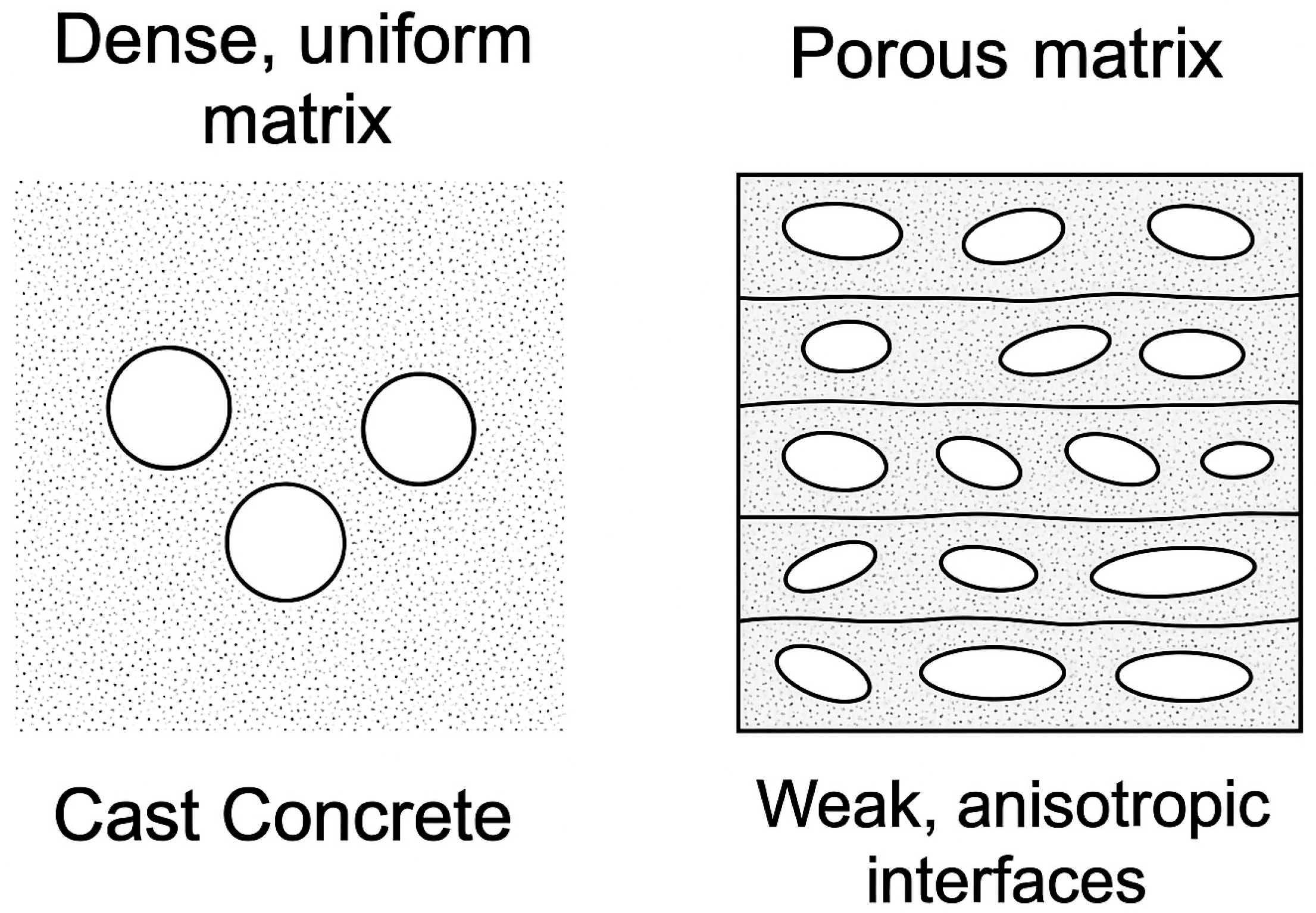
Figure 3 shows the comparative microstructural features of cast and 3D printed concrete.
The effect of freeze–thaw cycles on 3DPC is highly dependent on the heterogeneity introduced during the printing process. Differences in pore structure, moisture distribution, and bonding quality between layers lead to non-uniform internal stress development during freezing, which can accelerate localized damage. These heterogeneities are further amplified by the absence of vibration and the presence of cold joints, making printed elements more vulnerable to internal cracking and surface degradation. Moreover, sample size plays a crucial role in the freeze–thaw response. Smaller specimens often freeze more uniformly and may not represent the same damage mechanisms observed in larger printed components. Various studies in the literature have employed different specimen sizes and geometries, complicating the comparison of results. Therefore, there is a critical need for a comprehensive and standardized testing protocol specifically designed for 3DPC. Such a standard should not only consider the anisotropic structure and interfacial weaknesses of 3DPC but also provide clear recommendations on specimen size and shape to ensure consistent and comparable evaluation of freeze–thaw resistance across different studies.
In summary, the freeze–thaw durability of 3D-printed concrete is inherently challenged by its anisotropic microstructure, weak interlayer bonding, and high porosity at cold joints. These structural vulnerabilities result from the extrusion-based placement method and lack of compaction, distinguishing 3DPC from cast concrete. Understanding and addressing these unique characteristics through tailored materials and process optimization is essential for enhancing the resilience of 3DPC in cold climates.
4. Experimental Approaches and Durability Testing for 3DPC Under Freeze–Thaw
Assessing the freeze–thaw durability of 3DPC requires adapted testing strategies that reflect its anisotropic and layered structure. Traditional test methods like ASTM C666 [
45] or EN 12390-9 [
46], developed for cast concrete, are frequently employed but may inadequately capture the directional vulnerabilities and interfacial degradation specific to 3DPC. Nonetheless, these standards remain the foundation for durability investigations, with researchers often modifying them to consider printing orientation and build geometry.
Recent experimental programs have evaluated 3DPC durability under both laboratory-controlled and field-simulated F–T conditions. GivKashi et al. [
20] subjected air-entrained 3DPC specimens to ASTM C666 Procedure A, reporting the drop in compressive strength of air-entrained samples were 1.4–5.3% less compared to control specimens against the freezing and thawing cycles.
Tarhan and Sahin [
21] implemented a 360-cycle regime with horizontally and vertically cored specimens, finding enhanced durability in horizontal cores due to fewer interlayer defects. These directional differences are crucial in interpreting test outcomes and are often overlooked by conventional standards.
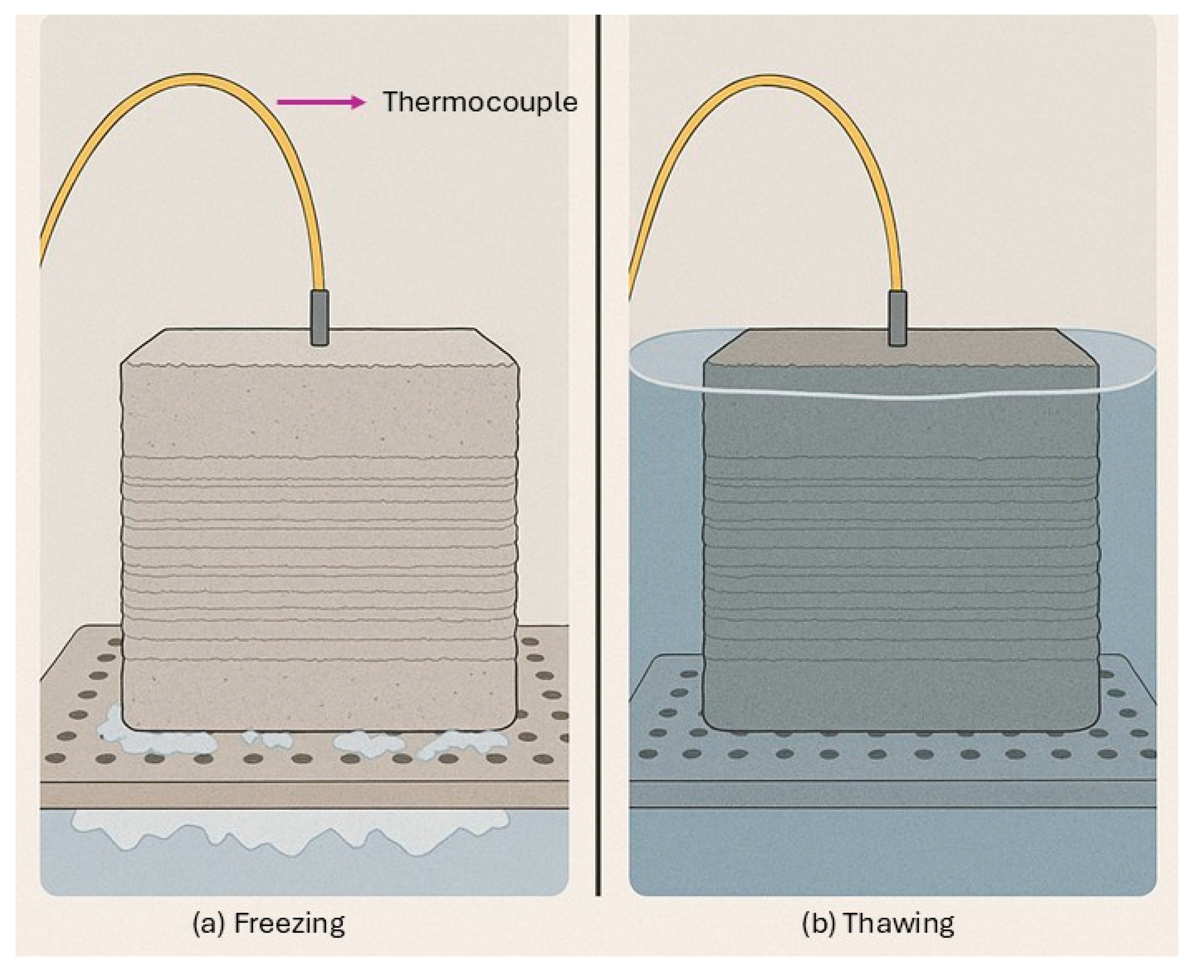
Figure 4 shows the experimental setup for F–T cycle exposure.
Liu et al. [
22] explored the use of X-ray CT and SEM to monitor pore structure evolution in 3D printed recycled aggregate concrete before and after F–T cycling. The analysis for X-CT was performed using an MS-Voxel 450 X-CT system (Tianjin Sanying Precision Instruments Co.) with a scanning resolution of 51.36 μm, a voxel size, a current of 1.3 mA, and a voltage of 385 kV. The acquired scan data were first reconstructed into tomographic images using VoxelStudio Recon 3D software. Then, parameters such as porosity distribution, pore volume, and three-dimensional pore geometry were extracted and analyzed using Avizo software. To enhance data accuracy, images from the top and bottom surfaces of the specimens were cropped, and a thin 2-voxel layer around the outer surface was removed to minimize potential edge artifacts caused by the cutting process.
Figure 5 illustrates the X-CT sample preparation. Their results showed that internal ellipsoidal pores and weakened ITZs significantly worsened mass loss and reduced the relative dynamic modulus, particularly at 100% RCA replacement.
Wang et al. [
23] used a 300-cycle exposure protocol to evaluate desert-sand-based 3DPC and highlighted progressive increases in porosity and reductions in matrix integrity, especially in printed vertical sections.
To support mechanical testing, microstructural analysis tools like Brunauer–Emmett–Teller (BET), mercury intrusion porosimetry (MIP), and low-field NMR are commonly used. These methods, as shown by Wang et al. [
26], help measure changes in porosity and matrix damage, making it possible to correlate them to the reduction in mechanical properties.
Similarly, Muy et al. [
27] quantified spalling mass over multiple intervals (7, 14, 28, 56, 91 cycles) to assess surface degradation in recycled fine aggregate 3DPC. In this study, the low mass loss observed during freeze–thaw cycles in 3DPC with 100% recycled fine aggregates (RFA) is attributed to the dense matrix formed by the low water-to-cement ratio (0.29), the high water absorption of RFA that enhanced internal curing [
47], and optimized printing parameters that improved interlayer bonding. These factors collectively reduced pore saturation and minimized stress concentrations during freezing, limiting microcracking and surface spalling even after 91 cycles.
Table 1 demonstrates a summary of freeze–thaw test protocols and performance indicators in recent 3DPC studies.
Overall, the diversity of experimental approaches underscores the need for F–T testing protocols tailored to 3DPC’s unique structural properties. Print orientation, interlayer properties, and material heterogeneity significantly influence degradation pathways. Current studies provide a valuable foundation but also highlight the necessity for standardized testing frameworks specific to additive construction, especially as 3DPC transitions from laboratory validation to structural-scale applications in cold climates. To conclude, current durability testing methods for 3DPC provide valuable insights but often fall short in accounting for its layered structure and directional weaknesses. While modified versions of conventional standards like ASTM C666 and imaging tools such as X-ray CT and SEM have been adopted, there remains a clear need for standardized testing protocols specifically designed for 3DPC. Such protocols should consider orientation effects, printing parameters, and specimen geometry to ensure reproducible and meaningful assessment of freeze–thaw performance.
5. Print Parameters and Process Optimization for F–T Durability
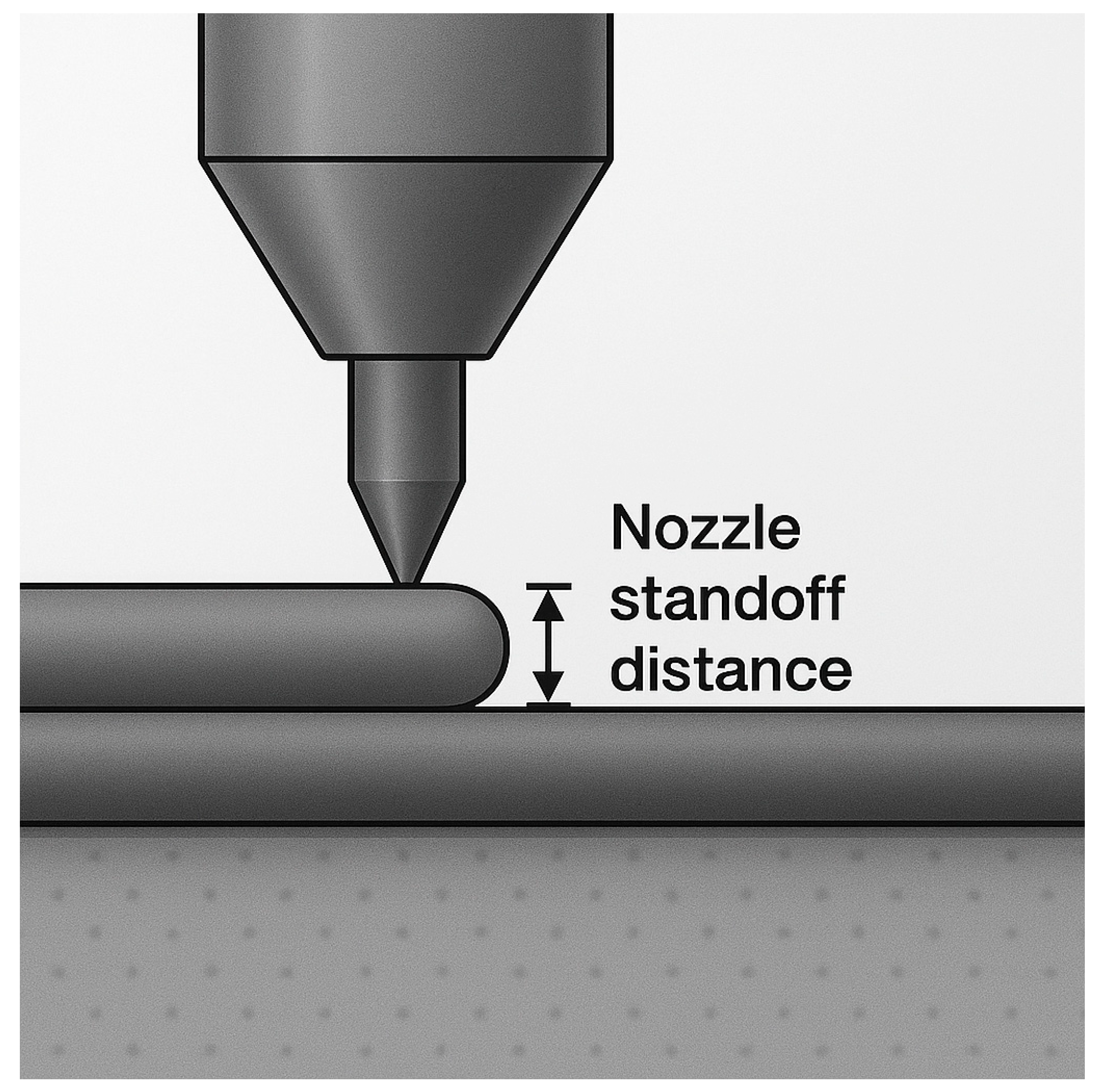
Freeze–thaw durability in 3DPC is strongly influenced by printing parameters such as nozzle standoff distance, printing speed, nozzle size, and build orientation. These factors affect interlayer bond strength, pore structure, and the overall homogeneity of the printed matrix. Nozzle Standoff Distance: The gap between the nozzle and the previously deposited layer determines the compaction level and bond quality. A larger standoff distance may lead to poor layer adhesion and increase interfacial porosity, which facilitates moisture penetration and accelerates F–T degradation. According to Wolfs et al. [
48], optimizing printing parameters such as interlayer interval time and surface dehydration significantly improves bond strength in 3DPC. Shorter interval times (e.g., 15 s) maintain higher tensile and flexural strengths, while prolonged delays (up to 24 h) reduce interlayer bonding, especially when surface drying occurs. Surface dehydration caused up to 51% strength loss, highlighting the need for controlled environmental conditions during printing. Nozzle height showed minimal effects compared to time and moisture control. Farahbakhsh et al. [
49] revealed that manipulating printing process parameters such as the nozzle standoff distance significantly enhances interlayer bond strength in 3D printing. They demonstrated that periodically varying to emulate localized compaction increased the interlayer bond strength by 41.2% on average. This optimization created interlocking geometries at the meso-scale, improving resistance to shear stress and mitigating cold joint vulnerabilities. According to Panda et al. [
50], reducing the time gap between layers from 20 min to 1 min increased tensile bond strength from approximately 0.25 MPa to 1.38 MPa. Similarly, decreasing nozzle standoff distance from 4 mm to 0 mm improved bond strength by over 60%. While varying the printing speed between 70 and 110 mm/s showed a minimal average effect, excessive speed introduced inconsistencies and reduced the reliability of bonding. A study by Huang et al. [
51] showed that the optimum combination, layer height of 8 mm, time gap of 10–15 min, and printing velocity of 1.6 m/min, led to a 7.6% and 6.2% increase in tensile and shear strength, respectively, compared to continuous printing (0 min time gap). Dong et al. [
25] observed better frost resistance when the standoff distance was minimized; they found that a layer height of 8 mm, 20 mm nozzle diameter, and 50 mm/s print speed resulted in minimal strength loss after 400 salt F–T cycles, highlighting the importance of consistent, well-compacted layering. Similarly, Wang et al. [
26] showed that smaller layer heights reduce porosity and improve interfacial adhesion, which is critical for limiting water ingress and microcracking. Printing Speed: Faster speeds may reduce deposition time and minimize cold joints, but they can also lead to poor fusion between filaments if not carefully managed. A moderate speed (e.g., 50 mm/s) as used by Dong et al. [
25], helps ensure consistent layer placement without compromising interface quality. Nozzle Size: Larger nozzles deposit more material per pass, potentially improving interlayer bonding due to increased pressure and extrusion rate; however, excessive diameter may cause surface defects and sagging. Build Orientation: The direction in which layers are built significantly affects F–T resistance. Vertically printed samples (Z-orientation) typically experience more interlayer cracking under F–T cycles due to weaker vertical bonding, as confirmed by Wang et al. [
23,
26]. Conversely, horizontally printed elements exhibit better resistance due to lower anisotropic stress.
To optimize these parameters for maximum F–T resistance, a stepwise empirical optimization approach was used. This method involved identifying key variables, systematically varying them through controlled experiments, and evaluating their impact on performance indicators such as mass loss, bond strength, and dynamic modulus retention after F–T cycling.
The optimization process can be described through the following algorithmic stages:
Step 1: Selection of influential printing parameters: Identify nozzle standoff distance, time gap between layers, and print speed as key variables affecting F–T durability.
Step 2: Experimental design and parameter variation: Conduct parametric studies varying each parameter within practical ranges (e.g., standoff distance: 3–30 mm; time gap: 0–30 min; print speed: 500–10,000 mm/min).
Step 3: Performance evaluation: Measure outcomes such as interlayer bond strength, porosity, compressive strength retention, dynamic modulus retention, and surface scaling after freeze–thaw cycles (up to 400 cycles in some cases).
Step 4: Multi-objective optimization: Analyze results to determine combinations yielding minimal degradation. For example, reduced time gaps and standoff distances improved bond strength by up to 60% and reduced surface scaling by over 50%.
Step 5: Iteration and validation: Validate optimal settings through repeated tests under different mix designs and environmental conditions.
It is worth mentioning that these factors are correlated to each other and by changing one of them, the optimal value of other parameters will change.
Figure 6 shows a schematic illustration of 3D printed concrete layers and the nozzle standoff distance.
7. Challenges, Limitations, and Future Perspectives
Despite the growing interest in enhancing freeze–thaw durability of 3DPC, several critical challenges and research gaps remain. The absence of standardized durability testing protocols tailored to the anisotropic and layered nature of 3DPC leads to inconsistent evaluations across studies, limiting comparability and practical implementation. Most existing research focuses on small-scale specimens under laboratory-controlled conditions, whereas real-world applications must address large-scale behavior, environmental variability, and long-term exposure. Additionally, the interplay between print parameters and material design is not fully understood, particularly in relation to interlayer bonding and pore network evolution under cyclic F–T loading. Numerical results from various studies demonstrate the variability of F–T performance. For instance, Tarhan and Şahin [
21] reported a 15% increase in residual dynamic modulus for horizontally cored specimens compared to vertical ones, demonstrating the directional dependence of durability. Similarly, Muy et al. [
27] showed that 3DPC with 100% recycled fine aggregates exhibited less than 1% surface spalling mass loss after 91 cycles, suggesting that properly designed 3DPC mixtures can offer excellent durability even with sustainable materials. Dong et al. [
25] demonstrated that optimized printing parameters and the inclusion of ferrochrome slag led to compressive strength loss of less than 8% after 400 salt F–T cycles, indicating promising resistance in aggressive environments. Future research should aim to develop unified testing standards for F–T resistance in 3DPC, investigate the combined effects of mechanical loads and environmental stressors, and utilize advanced imaging and digital modeling to optimize material–print–process interactions. Moreover, full-scale field trials and performance-based design approaches are essential to validate laboratory findings and ensure the resilience of 3D-printed infrastructure in cold climates. For future studies, the authors of this review paper suggest developing a comprehensive standard for evaluating the F–T resistance of 3DPC. This standard should include tests such as inter-layer bond strength reduction, shear strength loss, and mass loss after exposure to F–T cycles.
It would be valuable to develop a model that correlates the inter-layer bond strength of 3DPC before F–T exposure with its overall F–T resistance. This correlation should consider factors such as mixture proportioning and be based on a tailored F–T testing protocol. Advanced modeling approaches, such as artificial neural networks, could be used to predict a freeze–thaw resistance factor for commercially available 3D printing concretes using inputs like bond strength and material composition. The results synthesized in this review underscore the potential of optimized printing parameters, admixture selection, and microstructural control in enhancing the F–T resistance of 3DPC for cold-region construction. The identified strategies, such as reduced nozzle standoff distance, integration of nano-additives, and optimized interlayer timing, can directly inform the development of durable structural and non-structural elements in transportation infrastructure, housing, and precast facade panels.
8. Conclusions
This review highlights the key factors influencing freeze–thaw durability in 3D-printed concrete, with a focus on the role of material selection, print parameters, and microstructural characteristics. Compared to cast concrete, 3DPC is more vulnerable to F–T damage due to its anisotropic layering and weak interfacial bonding. Among the various strategies reviewed, the use of nanomaterials, like nano-zinc oxide, has shown remarkable potential in enhancing durability. Nano-ZnO acts as a microstructural densifier and nucleation agent, reducing interfacial porosity and refining the pore network, which are critical factors for improving F–T resistance. Experimental findings have shown that compressive strength retention rates exceeding 95% are achievable using 0.5% nano-ZnO in geopolymer-based 3DPC, while AEAs have limited strength loss to only 1.4–5.3% under standard freeze–thaw regimes. Additionally, optimized printing parameters such as reduced layer height and minimized idle time resulted in surface scaling reduction by over 50% in some studies. Additionally, advanced imaging techniques like X-ray CT and SEM have proven valuable in identifying pore structures and degradation pathways, guiding the design of more durable 3DPC. Despite progress, several limitations remain. The practical implications of the reviewed findings suggest that carefully selected mix designs, including the use of recycled aggregates and nano-modified binders, combined with optimized printing strategies, can significantly improve the freeze–thaw durability of 3DPC. These insights can be translated into actionable practices for printing durable sidewalk panels, retaining walls, and precast facade components in cold climates. Current testing protocols are not well-suited to capture the directional vulnerabilities of 3DPC, and most studies are confined to lab-scale evaluations. To ensure long-term performance in cold climates, future research should focus on developing standardized test methods, conducting full-scale trials, and integrating microstructural modeling with mechanical performance metrics. A comprehensive approach that combines optimized materials, printing parameters, and evaluation methods is essential to unlock the full potential of 3DPC in freeze–thaw environments and promote its safe and durable use in real-world construction.

