1. Introduction
Flooding and other hydraulic causes of bridge failure are of prime concern all over the world. The AASHTO LRFD Bridge Design Specifications (2010) states that “A majority of bridge failures in the United States and elsewhere are the result of scour” (C2.6.4.4.2) [
1,
2]. Scour caused by the erosion of streambed material due to flowing water was responsible for more than 53% of bridge failures in the United States [
3]. Cook et al. [
2,
4] estimated an annual hydraulic collapse frequency of approximately 1/5000, and there are about 504,000 bridges over the waterways in the United States [
5]. As per the Federal Highway Administration (FHWA) national bridge scour evaluation program, each state needs to evaluate its bridges for potential flood damage for a 100 to 500 year return period [
6], and scour susceptible bridges need to be retrofitted or replaced based upon the existing condition of the bridge. Researchers all over the world have recognized the importance of reliable scour monitoring methods and frequent bridge scour vulnerability assessments of the existing bridges.
Scour resulting from hydrostatic and hydrodynamic forces at the streambed and channel margins that remove soil and alluvial sediments surrounding bridge piers, exposes the bridge foundation and subjects the bridge structure to preemptive structural interventions or earlier than anticipated infrastructure replacement results. The properties of the soil and alluvial sediments surrounding the bridge foundation can determine the degree of scouring. However, the conventional analysis of bridge scour treats scour depth as the prime or major parameter of scour analysis [
2].
Several studies have been conducted to study the effect of scour on the performance of bridge substructure and superstructures: Avent and Alawady [
7] and Lin et al. [
8] studied the effects of scour on the buckling capacity of a bridge pier; McConnell and Cann [
9] investigated scour effects on the pushover behavior of a bridge; Klinga et al. [
10] conducted buckling, longitudinal and transverse pushover analyses, and modal analyses of a scoured bridge; and Alipour et al. [
11] considered earthquake and scour scenarios to determine the probability of bridge failure under extreme conditions. Antonopoulos et al. [
12] studied the dynamic response of bridges with shallow foundations under scour and earthquake conditions.
In the literatures, most researchers would differentiate between the impacts of scour on the lateral behavior of piles as either cohesive or non-cohesive soil cases [
8,
12,
13]. This is because scour hole formation (mass losses surrounding a bridge pier) in cohesionless soil can attain maximum depth within a few days, whereas, in cohesive soils, this process can take months or even years. Lin et al. [
14] demonstrated the importance of considering the stress history of cohesionless soil to accurately determine the lateral behavior of pile. Jiang et al. [
15] proposed an improved analytical method (IAM) to analyze laterally loaded pile groups in sand considering various scour hole dimensions. Liang et al. [
16] studied the effects of extreme scour on the buckling of bridge piles considering the stress history of soft clay. Finally, Ben et al. [
13] demonstrated the impact of stress history in evaluating scour effects on the lateral behavior of monopiles in soft clay.
Most of the research conducted were primarily focused on local scour surrounding single piles. In the majority of cases, these piles were analyzed for vertical load or lateral loads, separately. Where combined loading is considered in the literature, there is a conflict in opinions on the predicted behavior of drilled shafts: Jain et al. [
17] and Phillips and Lehane [
18] reported a reduction in the lateral displacement due to the presence of a vertical load, whereas other studies suggested an increase in lateral deflection under vertical load [
19,
20]. Achmus et al. and Hung et al. [
21,
22] observed that there was an interaction between axial and lateral loads in cohesive soils, which can indicate that the axial and lateral load interactions are soil type dependent. Unfortunately, there are insufficient case studies to definitively differentiate the combined load effects on piles on different soil types.
It is important to point out that scour is a complex, multi-physics problem involving several factors, including river hydraulics, the geometry and stiffness of the embedded structure (pier) and the sites geological conditions.
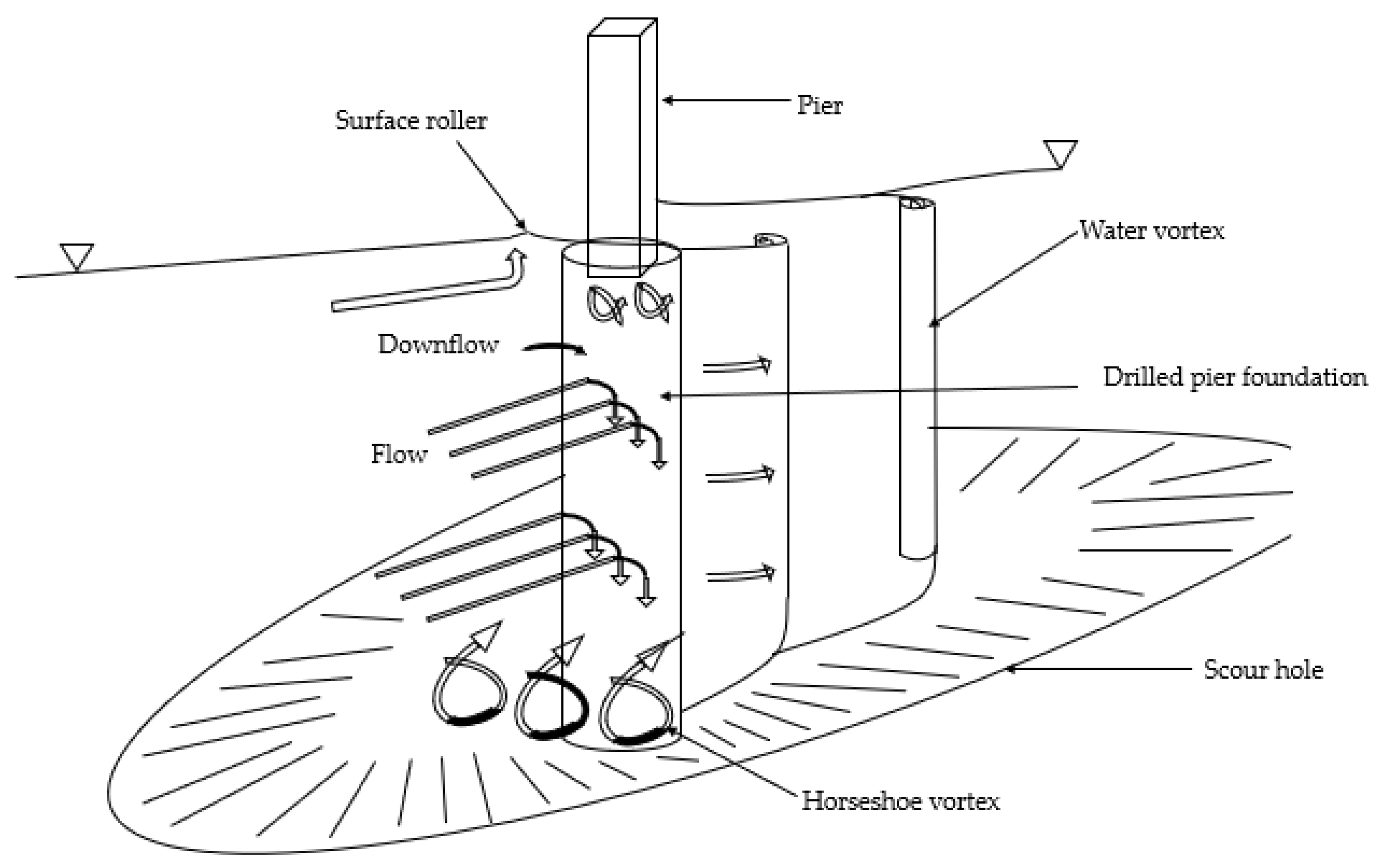
Figure 1 shows the schematic of a scour hole formation surrounding a single pier, where the rapid moving water flowing against the pier forms vortices and scour generally occurs in an area at the base of the piers affected by the vortices. For example, a horseshoe shaped vortex resulting from a pileup of water on the upstream side and the acceleration of flow at the nose of the pier, removes bed material around the pier base and scoops a hole around the pier (scour hole). The local scour around the bridge pier from the horseshoe vortex is due to the high bed shear stresses created by the acceleration of the flow near the pier. With increasing flooding events, this scour hole gets deeper and further washes out the soil around the adjacent piles. As a result, the scour hole extends around the pile, and the scour depth increases over time.
If the local scour problem is not corrected, the flow pattern around a pier can become altered further, resulting in the expansion of local scour holes forming a global or combined scour that can cause the loss of supporting soil between piers. Unfortunately, only limited studies have been published on the subject of combined or global scour effects on bridge piers: notably, Ismail et al. [
23] conducted laboratory experiments to compare the scour depths and patterns around a single pier and two piers in a side-by-side arrangement. They concluded that the local scour process is mainly governed by pier spacing, the horseshoe vortex and reinforcement elements around the piers. Several laboratory studies have been carried out to investigate the relationship between pier spacing and maximum scour depth around two piers in a side-by-side arrangement [
24,
25,
26]. To the best of the authors’ knowledge, there is no literature on the effect of scouring between two side-by-side piers with consideration of the loading on piles. Thus, the aim of this study is to investigate the effects of local scour around the single pier located on banks. This study is further extended to investigate the effects of the potential widening of local scour holes (combined scour) on pile behavior.
In this paper, numerical analysis using the finite element (FE) modeling technique is used to study the combined scour effects between two piers-on-bank bridges for the Phillips Road bridge in Charlotte, North Carolina. The scour problem for piers-on-bank is usually not considered because it is always assumed that the waterway basin is sufficiently deep to accommodate the design flow of the stream water. Piers-on-bank bridges are common for auto crossings over small streams with sites not suitable for culverts.
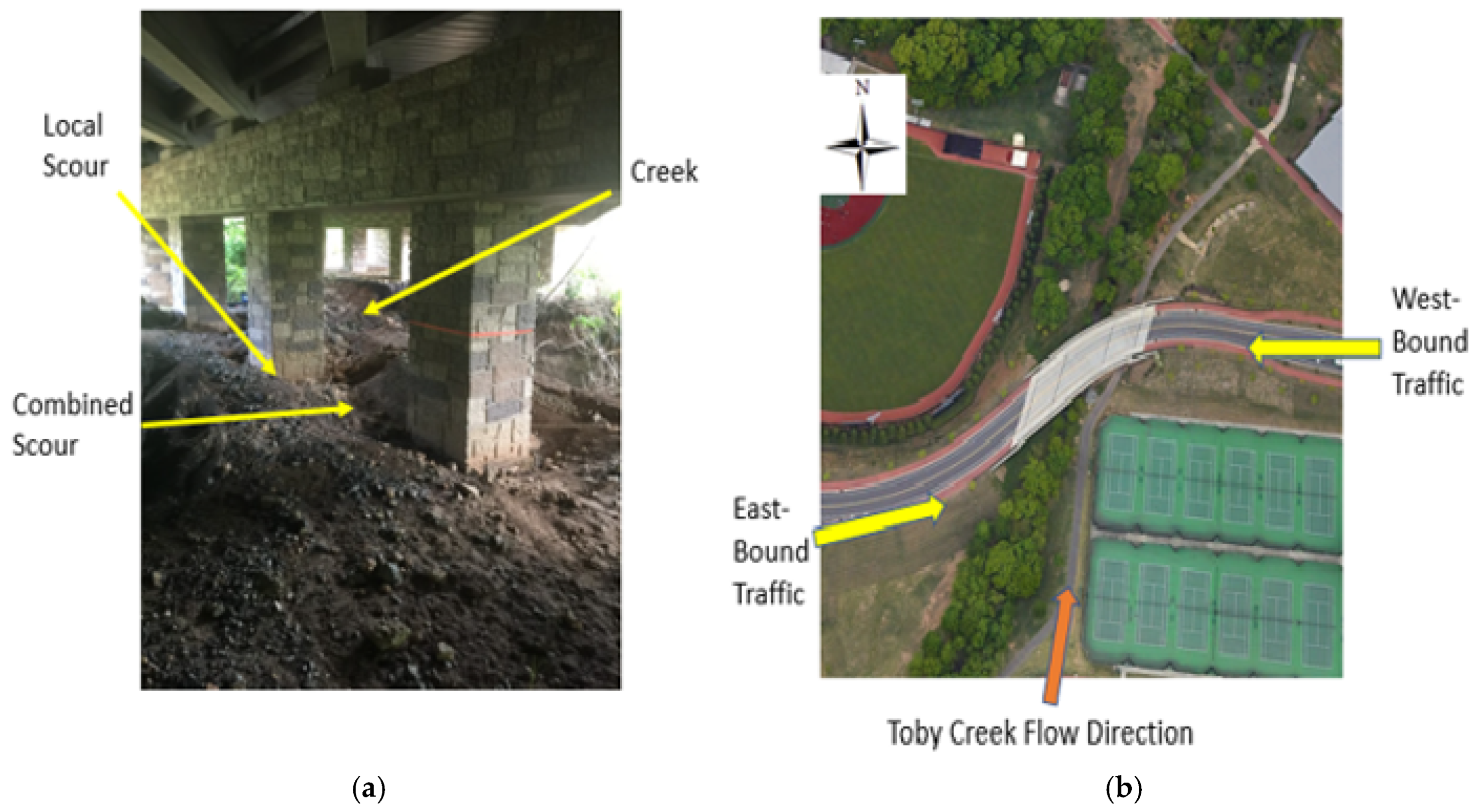
Figure 2 shows the Phillips Road bridge and the scoured piers. The bridge spans across the Toby Creek and accommodates a four-lane traffic pattern. In the case of Phillips Road bridge, frequent high flows resulting from low to moderate return rainfall events immersed most of the active channel and channel margins underneath the bridge, resulting in significant scour around multiple bridge piers. The numerical modeling simulated the local and combined scours between two adjacent piers-on-bank for three different loading scenarios and the results are presented within. The objective of the present study is to investigate the potential effects of the premature scours on the bridge piers.
1.1. Local and Combined Scour of the Phillips Road Bridge
Local scour is commonly seen around bridge piers located in the riverbed. However, local scour holes are also frequently visible near the piers located on the riverbank (piers-on-bank). At the Phillips Road bridge site, repetitive cycles of heavy flooding cause the overtopping of the floodplains and the rapid flood water scooped scour holes around the piers on the embankments (
Figure 2a). Phillips Road bridge sits above Toby Creek, which is a headwater tributary that rises in the Newell community of Charlotte, North Carolina. The creek drains approximately 13.3 km
2, and discharges into the Mallard Creek, which is a tributary of the Yadkin–PeeDee River system. Toby Creek has an estimated average discharge of 0.17 m
3/s and a mean flow velocity of 0.274 m/s [
27]. The total stream length is 6.68 km. The width of the creek at the bridge at the low flow stage is approximately 3.0 m and has a maximum bank full depth of 2.14 m. The constricted river cross section underneath the bridge, combined with high flow velocities during episodic runoff events, has resulted in significant bank erosion and has induced localized scour at the piers on both streambanks.
As the flooding recedes, unlike for the piers-in-the-river case, these scour holes at the Phillips Road bridge piers do not get filled in with sediments. As a result, large areas of soil between the adjacent piers were exposed to further erosions. Eventually, the erosion of soil over a widened area between the adjacent piers resulted in a groove formation between the piers, which is termed as “combined scour”.
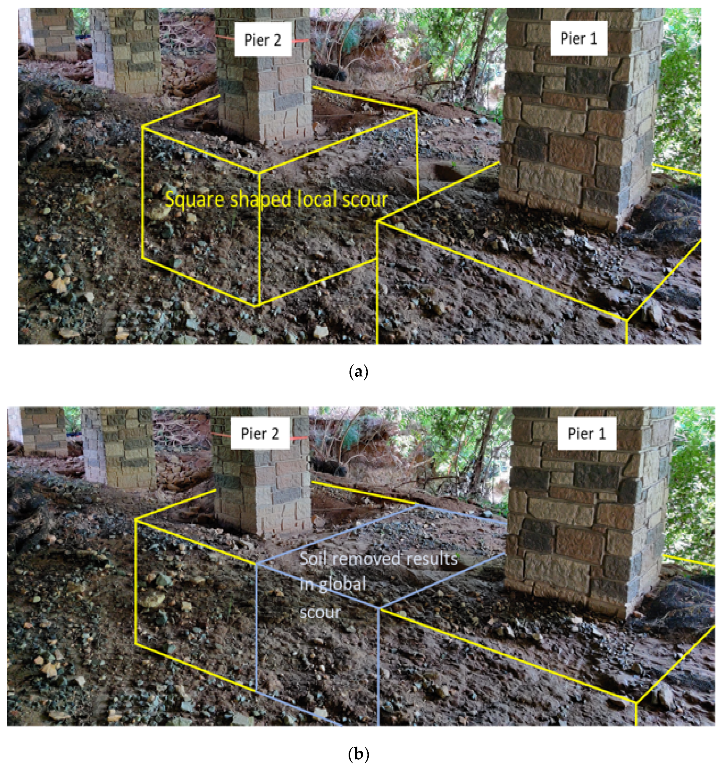
Figure 3 shows close-ups of the scours at the Phillips Road bridge. Specifically, the scours occurred at the west side of the north-flowing creek.
Figure 3a shows the marked square-shaped local scour and
Figure 3b shows the indication of the connection of the local scours to form the combined scour. The square-shaped local scour assumption is to provide ease in the numerical modeling. The actual scour is more rounded and complicated by loose sand and coarse gravel. Subsequent numerical models are built, based on these two pier scenarios.
Current scour evaluation methods are based on observations and predictive evaluations and have relied on a single parameter: “scour depth”. Most of the studies on scour depth estimates are based on empirical equations and various equations have been proposed to determine the scour depth based on historical data [
28,
29]. The depth equation proposed in Hydraulic Engineering Circular No.18 (HEC18) [
30] is the most commonly used, which is expressed as:
where
ds is the scour depth,
b is the pier width and
y is flow depth at the upstream of the pier.
K1,
K2 and
K3 are the correction factors for the pier nose shape, angle of attack flow and bed condition, respectively, and
F = Froude number.
Phillips Road bridge (
Figure 2) is a three-span continuous bridge that spans Toby Creek (south to north flowing). The bridge has a total length of 50.6 m with two end bents and two intermediate bents. Bent 1 consists of six bridge piers connected through a pier cap and supported by drilled shaft foundations. Bent 2 is made up of five piers connected through a pier cap. Two end bents are founded on steel pile-supported strip footing. Phillips Road bridge has a clear roadway width of 9.8 m and supports two traffic lanes, each with 4.9 m width. The overall width of the bridge deck is 15.5 m.
1.2. Numerical Modeling of Scour around Bridge Piers—A Brief Review
Numerical analysis methods, such as the finite difference (FD) and the finite element (FE) methods, have been used extensively in the study of soil–pile interactions [
21,
31]. A review on the different techniques for bridge scour analysis, which include the p–y method, beam on Winkler method and soil spring method, shows that the most widely used technique is the p–y method of analysis of laterally loaded piles. Klinga and Alipour and Lin et al. [
10,
32] developed p–y curves from full-scale test results. However, the p–y method and the more classical beam on Winkler foundation methods do not consider the three-dimensional nature of the pile–soil behavior and its effect on the performance of the pile. As a result, more robust FE methods have been used: Mardfekri et al. [
33], Strömblad [
34], Salim [
35] and Youssouf et al. [
36], are some of the studies that employed three-dimensional FE methods to study the effect of soil–pile interaction on laterally loaded piles. Senturk and Pul [
37] performed three-dimensional finite element push-over analyses of bridge piers considering the nonlinear behavior of reinforced concrete and soil under quasi-static loading. Khodair et al. [
31] compared the results obtained from the finite difference (FD) method and FE method to study the effect of pile–soil interaction under axial and lateral loads.
2. Development of Finite Element Model
The problem to be investigated can be best described as the effect of local and combined scours on two in-line drilled shafts. A comprehensive finite element model of the case study bridge pier was prepared using finite element analysis (FEA) software, ABAQUS [
38], where one individual drilled shaft was first modeled using 3D, solid deformable elements and then a two-drilled shaft model was developed. These drilled shafts were protruded 15.24 cm above the ground level and were embedded through multilayered alluvial and residual soil deposits that were identified at the Toby Creek site. The distance between these two piers is 4.2 m. To minimize boundary effects, the soil domain was modeled up to 10 times of the diameter of the pile from the center. As suggested in previous studies [
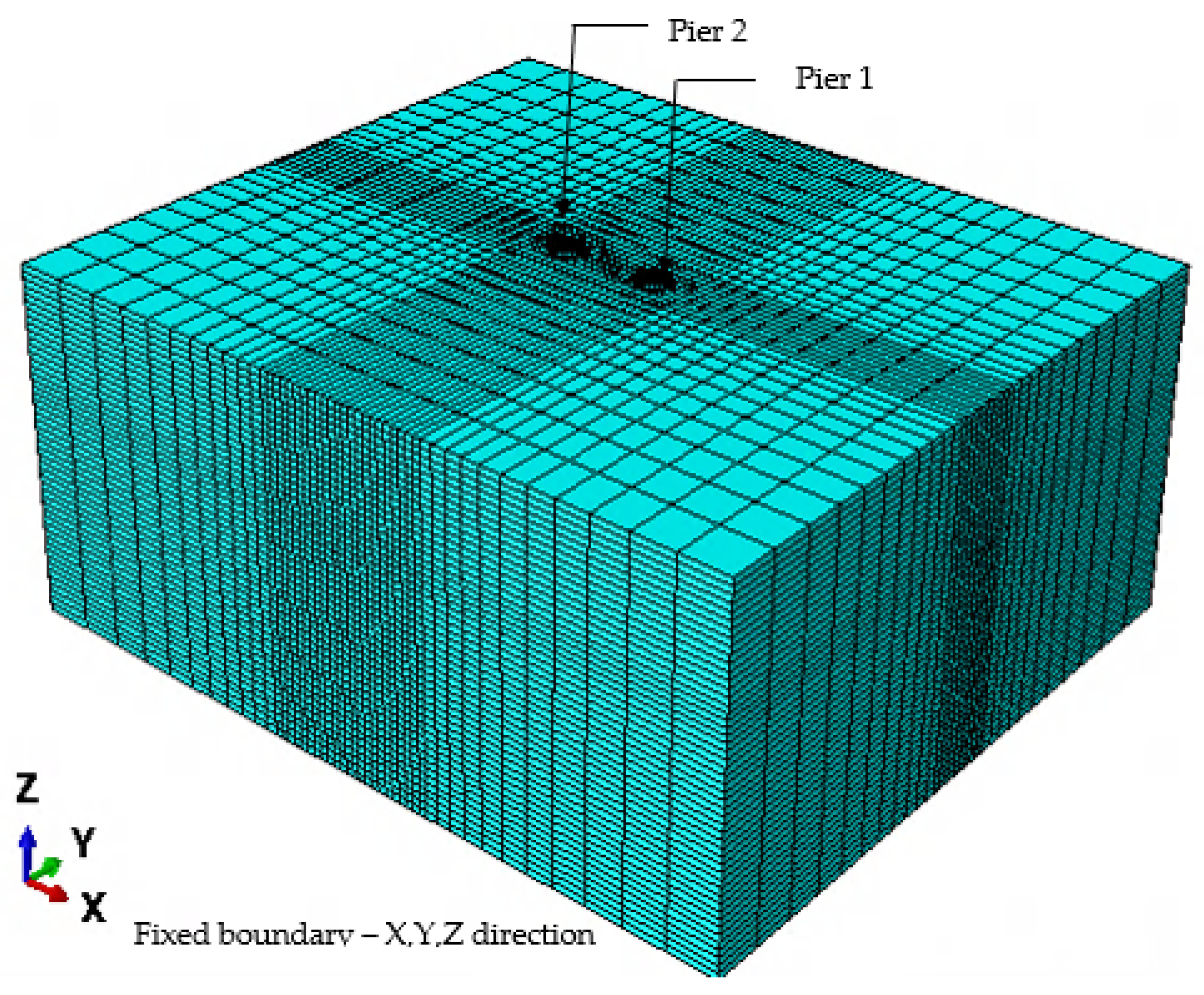
39], the modeling of the soil for a more considerable distance would help to avoid boundary effect on simulation results. Soil is extended to 2.13 m below the actual length of the shaft. The size of the FE model domain is therefore 38.4 m × 33.5 m ×15.1 m. The bottom of the pile was fixed to simulate the embedment of pile in weathered rock at its tip. The lateral and bottom sides of the model domain were fixed and restrained against translation in all directions.
Figure 4 shows the full FE model defining the problematic piers and surrounding soils. Additionally, the modeling of the local and combined scour scenarios are shown in
Figure 4.
Pile–soil interaction is a three-dimensional problem, and the effect of scour on the pile is highly dependent on pile–soil behavior. By removing the soil around the pile, scour significantly reduces the stiffness of the soil. Soil is highly anisotropic and exhibits different behavior in different directions. Thus, to model the 3D continuum nature of the soil, both pile and soil are modeled using 3D, eight-node, reduced integration elements. The longitudinal and transverse reinforcement of the pier was modeled using one-dimensional rebar elements. These solid and rebar elements were defined by first-order linear interpolation. The FE model comprised of a total 79,866 linear continuum brick elements (C3D8R) defined for the piles and soil. To minimize the computational time, a finer mesh was selected for the soil region near the pile and relatively coarser mesh was created towards the boundary of the soil block.
2.1. Geometry and Material Properties
2.1.1. Drilled Shaft Properties
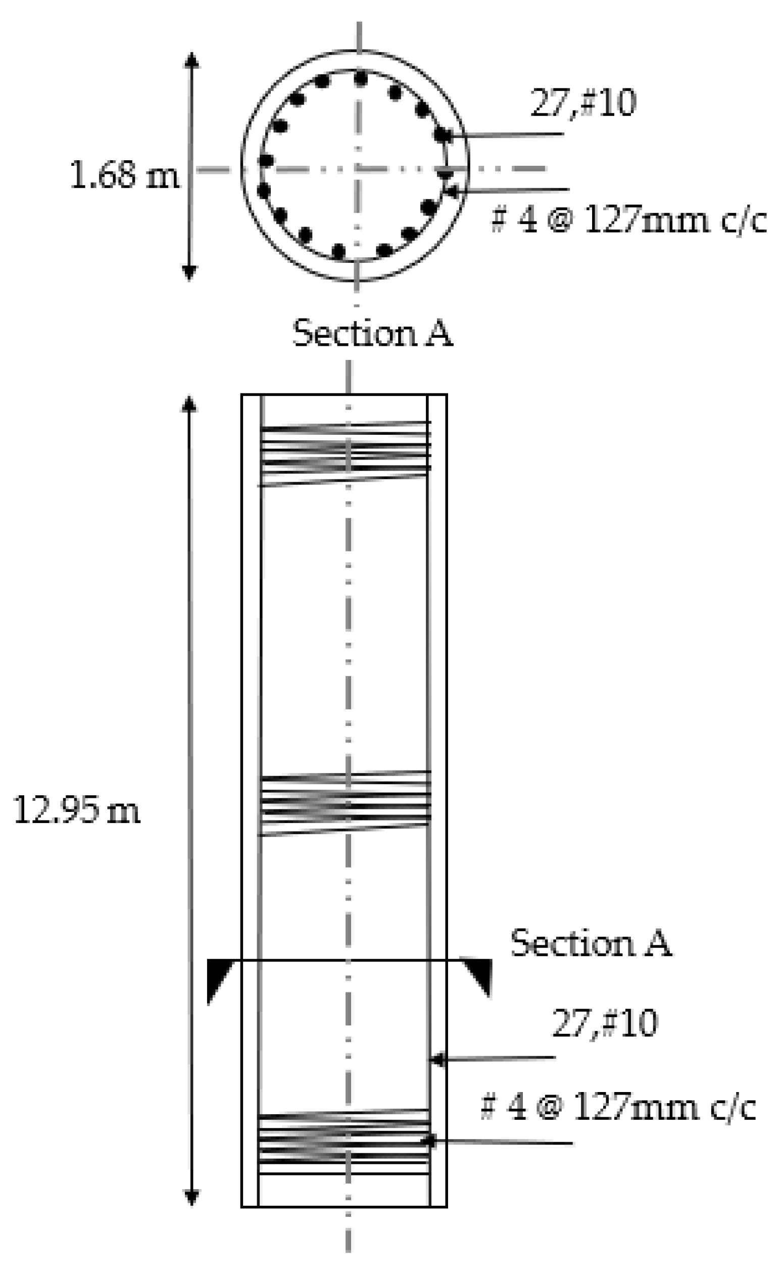
The reinforced concrete drilled shafts are 1.68 m in diameter and 12.95 m in length. The cross section of the pier is shown in
Figure 5. The “embedded region” constraint in ABAQUS was used to model the longitudinal and transverse reinforcements of the piles. The pile reinforcements comprise of 27 #10 longitudinal rebars with a clear cover of 127 mm. The shaft’s transverse reinforcement or lateral ties are #4 deformed bars spaced at 127 mm c/c. A bridge pile is typically assumed to behave non-elastically up to a significant deflection level and, thus for this study, the pile material is considered elastic. Hence, the nonlinear behavior is dominated by soil deformation behaviors. This consideration can reduce the computational time during the analysis. The material properties of the reinforced concrete and steel are depicted in
Table 1.
2.1.2. Soil Material Model
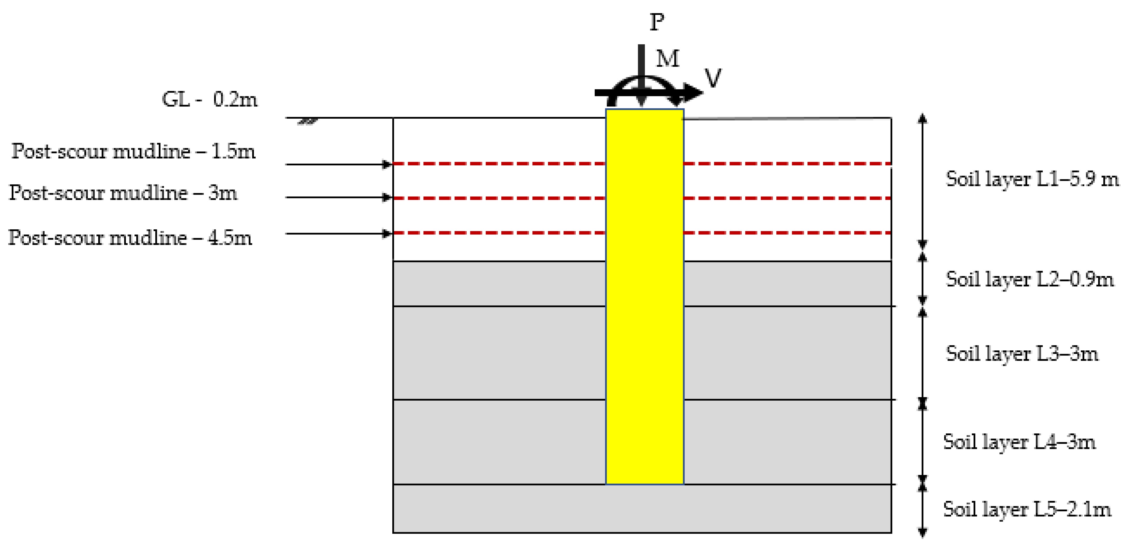
The typical behavior of laterally loaded shafts includes nonlinearities in the soil and pile resistance. Soil nonlinear behavior is modeled using the Mohr–Coulomb plasticity model in ABAQUS. As described earlier, the soil domain is assumed as multi-layered geo-materials comprised of five layers of alluvial soil, residual soil and with the bottom layer of weathered rock, as shown in
Figure 6.
Table 2 shows the material properties used in the models.
2.1.3. Pile–Soil Interaction
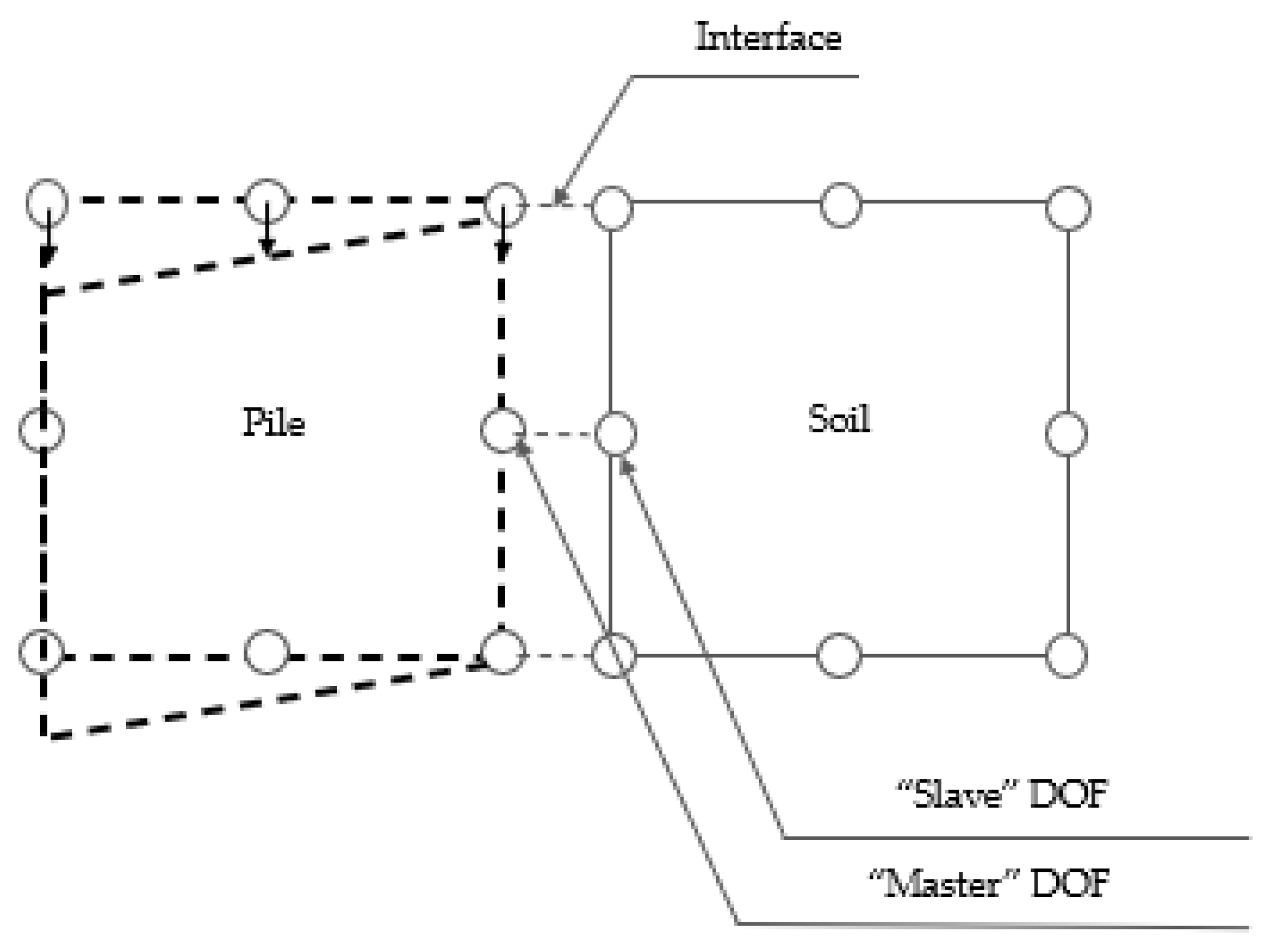
The pile–soil interface was modeled using ABAQUS contact features with identified master (pile) and slave (soil) sides, which allows soil pile separation and models the frictional behavior at the interface. The master–slave contact pair formulation allows the simulation of the load transfer between the pile and soil, as show in
Figure 7. As can be observed, the piles being stiffer was selected as the master surface, while the soil domain was the slave surface. The separation between the soil and pile contact interface is a critical feature of the modeling technique that models the actual scenario of the bridge piers.
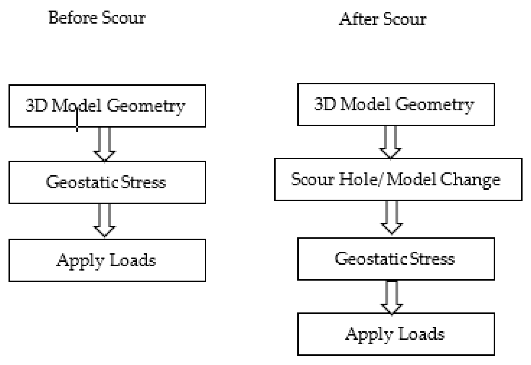
In ABAQUS, surface-to-surface contact discretization can be applied between two material types and, in the current modeling, a penalty enforcement method was selected to assure the proper load transfer between the pile and the soil. The penalty method enforces the load transfer in the normal direction by constraining the contact interface. In this study, a default stiffness value (defined as a ratio to the element material stiffness) was selected for the linear contact stiffness. The shear behavior between pile and soil was described using a Coulomb friction coefficient of 0.3. No limit penalty friction formulation was used to depict the tangential behavior between contact surfaces. The FE analysis of the scour simulation was performed using multiple steps, as shown in
Figure 8. In order to ensure equilibrium, the “geostatic” option is applied prior to and after the scour condition simulation. This step ensures that the geostatic stresses are in equilibrium.
2.1.4. Scour Simulation
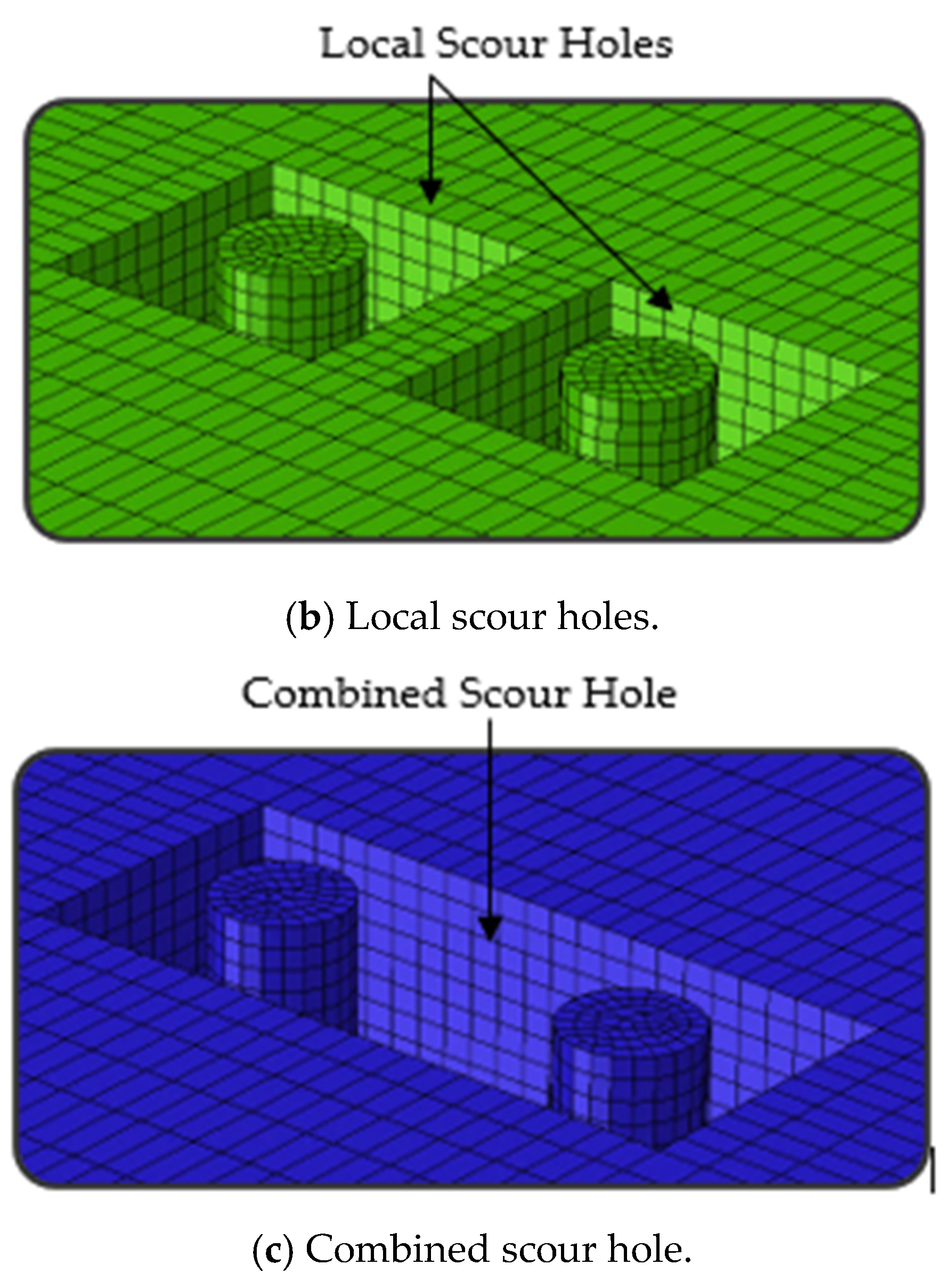
Scour holes of a rectangular shape were created in ABAQUS using an element removal “ER” technique, in which elements were removed surrounding each pile. This approach ignored the hydrodynamic effects in scouring and represent an instantaneous loss of soil around the piers. The general static step using the “model change” option was employed so that the initial model could be further analyzed after ER. Before the defined ER step, ABAQUS stored the forces exerted by the scour hole region on the remaining part of the soil domain at the boundary nodes. The nodal variables of the removed elements were not changed directly when the elements were removed [
35]. The element removal method used to simulate scouring represents a permanent soil mass loss and these elements were not reactivated again for the remaining analysis. Hence, the corresponding master–slave contact pair was removed to avoid any convergence issue.
Figure 9 shows the results of ER in the numerical models:
Figure 9a shows the surrounding soil sans the piles and
Figure 9b,c show the local scour holes and the combined scour hole with the two piles in place.
Initial stresses in the soil were simulated by applying geostatic stress in ABAQUS. The user-specified predefined stress field was created by defining the effective vertical stress between any two points within each soil layer, with the lateral earth pressure coefficient and vertical effective stresses calculated using the following equations, respectively:
where
γsat = saturated unit weight of the soil,
h = depth to the soil layer of interest,
ϕ = coefficient of friction for ith soil layer and
k0 = the lateral earth pressure coefficient, which is determined and used as data input in the calculation of the lateral effective stresses in the soil.
2.1.5. Loading Scenarios
In contrast to conventional design practices of considering separately the axial and lateral loads on the pile top, this study considered the combined effects of loading applied to the bridge piers, which is a better representation of the actual condition of existing bridges. In the actual working conditions, ongoing traffic would subject the bridge piers to different combinations of axial loads, lateral loads and moments, as a result of traffic coming from both (westbound and eastbound) directions. Different load combinations pertaining to maximum axial, maximum lateral and maximum moment cases considered in the original design of the bridge shafts were analyzed for evaluating scour effects in this study. The static loadings, shown in
Table 3, were applied to each pier through a reference point identified at the top of the pier’s cross-section.
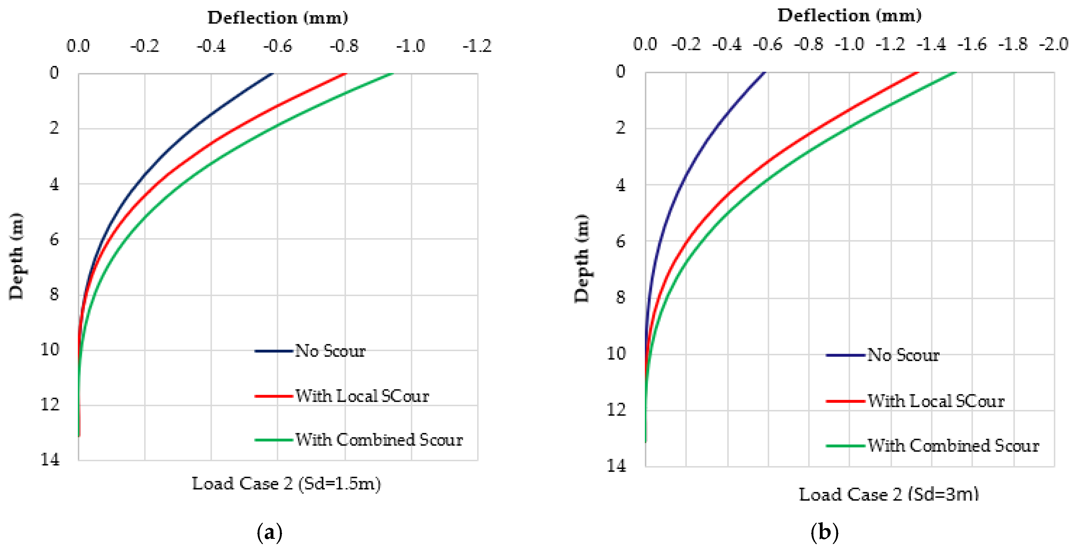
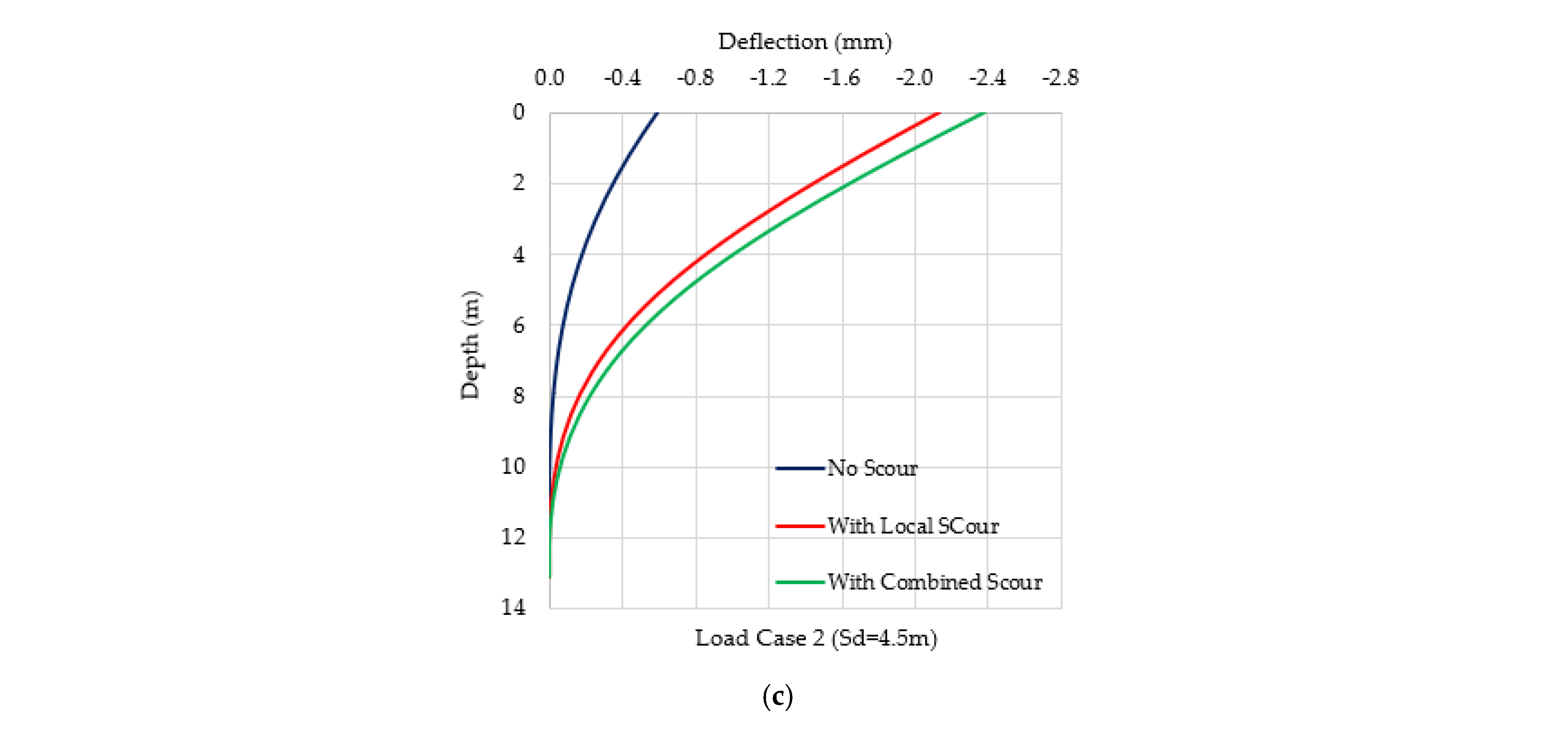
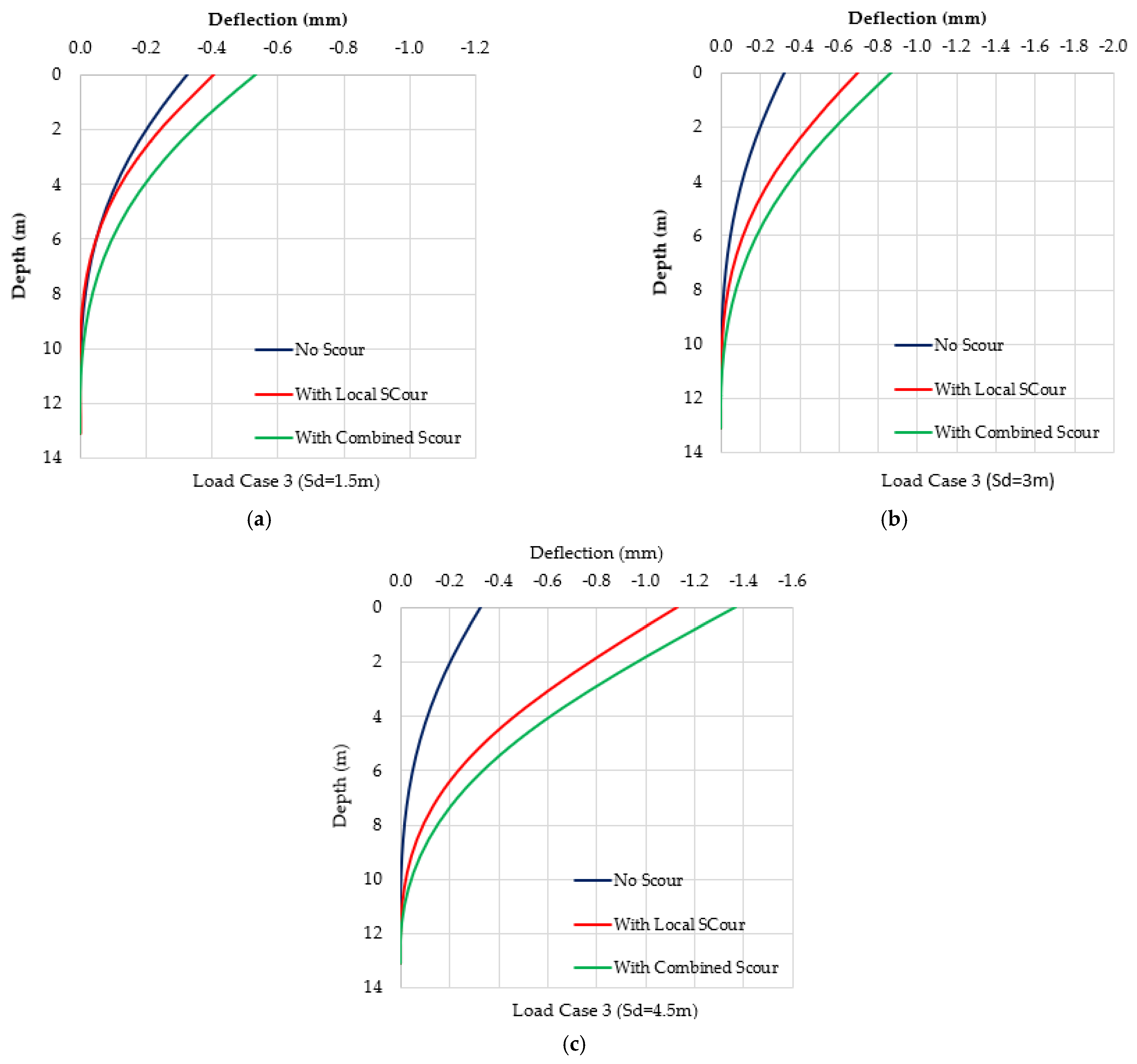
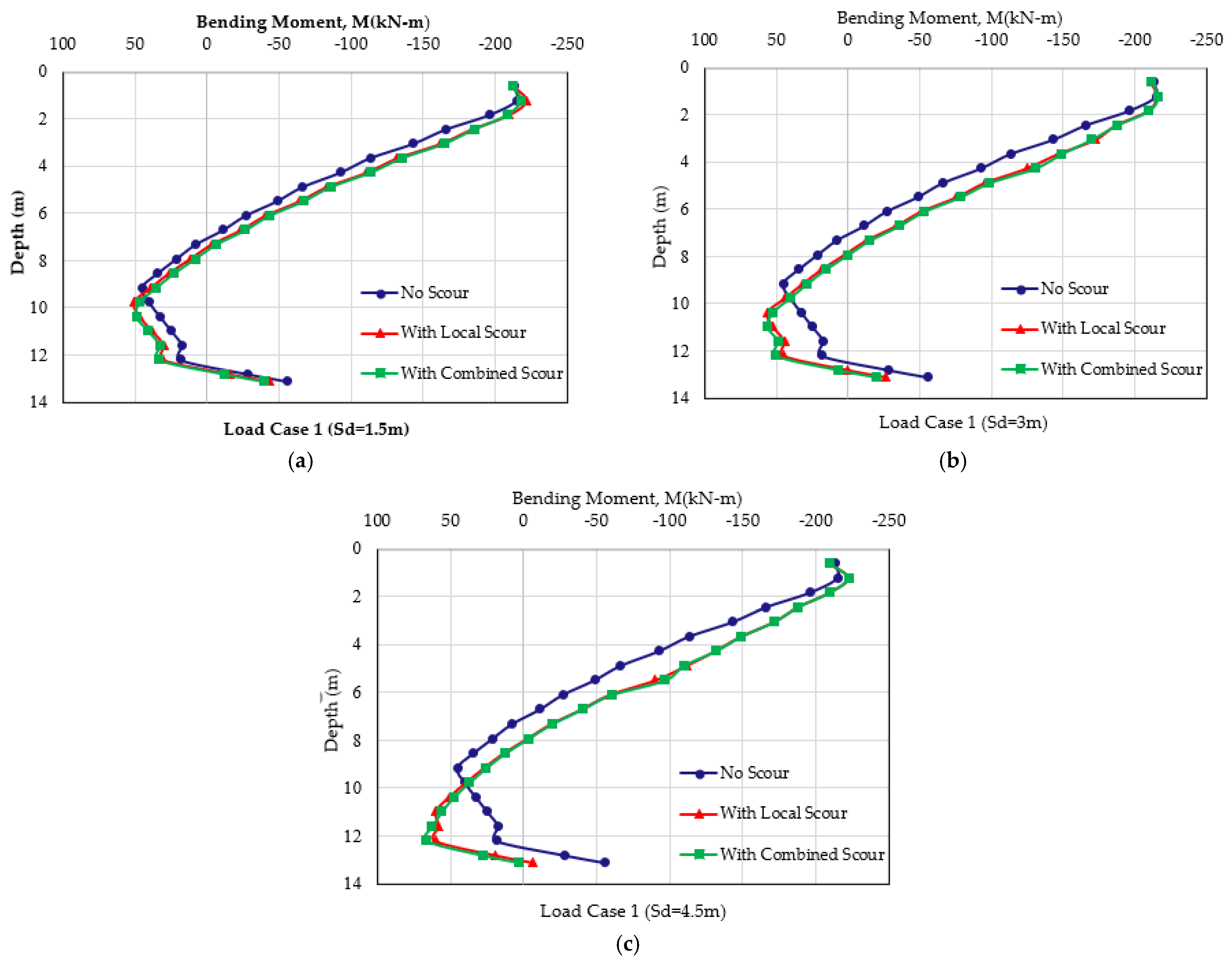
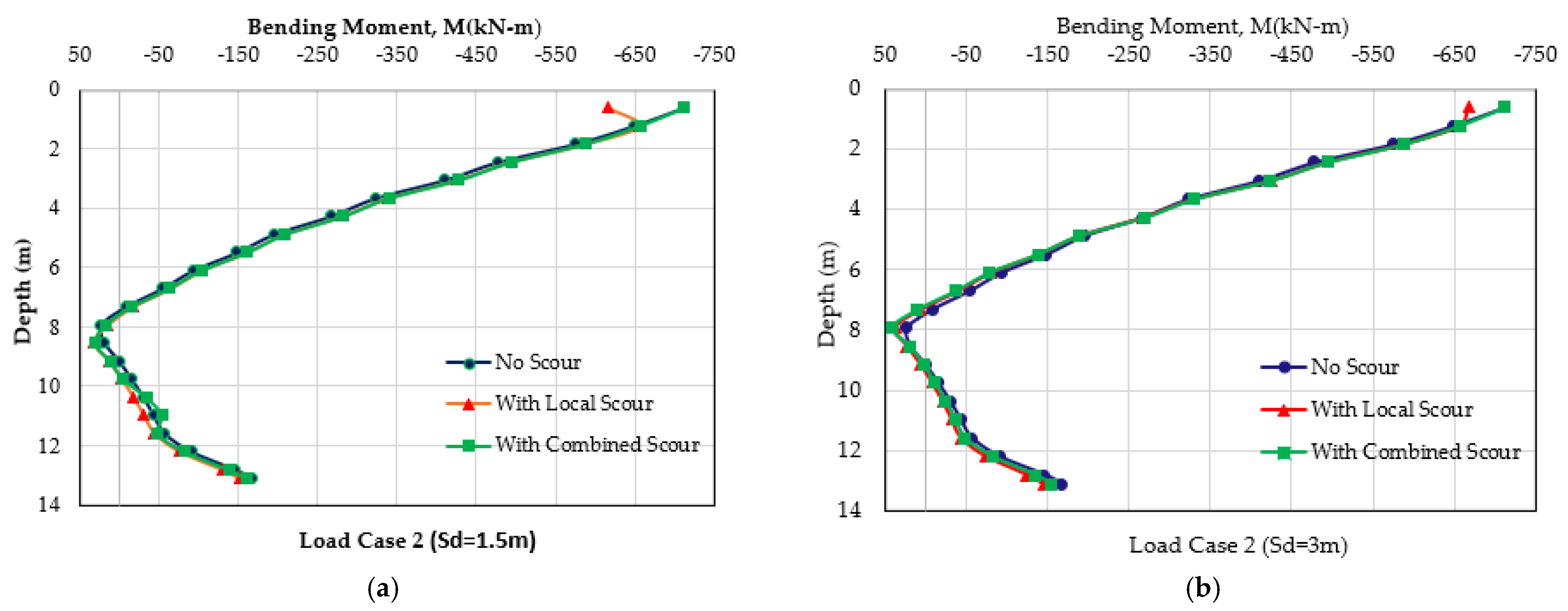
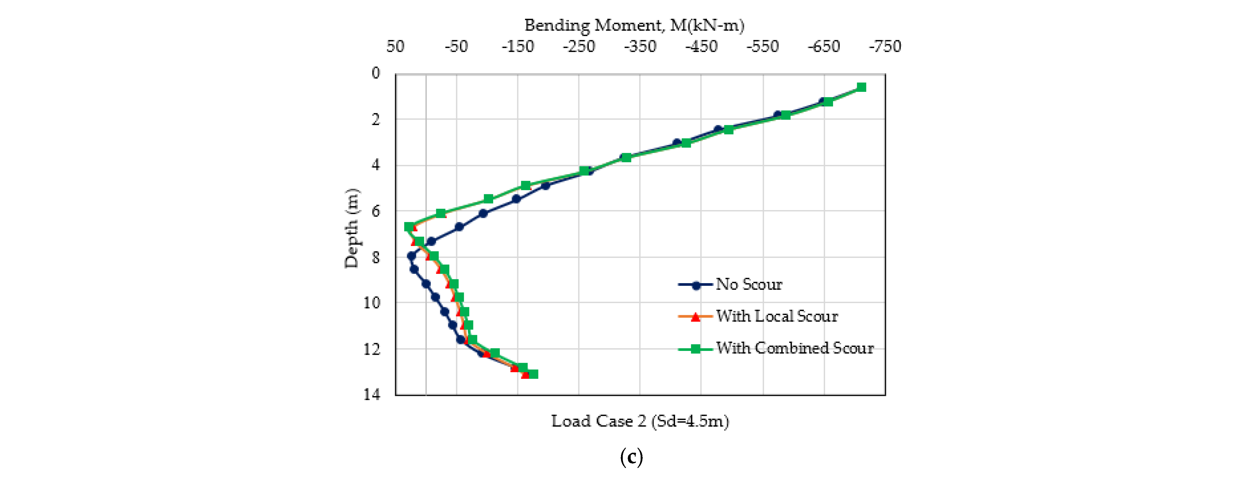
A total of three load cases are considered in order to generate the maximum axial stress and deformation (load case 1), the maximum lateral pressures (load case 2) and the maximum bending moment in the piers (load case 3).
To investigate the combined scour effect, two piers were considered in the current study. A parametric study has been performed considering different scour depths, including existing scour depths at the Phillips Road bridge. The degrees of freedom of the elements at the top of the pier were constrained using a kinematic coupling to limit the motion of the coupling nodes to the reference node.
4. Conclusions
In this paper, three-dimensional nonlinear FE models with scours were used to analyze the effects of scouring on a pier-on-bank bridge with congested waterways and frequent over bank flooding. Spanning Toby Creek, Phillips Road bridge has experienced scouring problems despite its piers-on-bank design. Specifically, this paper investigated the impact of local and combined scours on two adjacent drilled piles under the combined actions of axial load, lateral load and moments. The scour was modeled using the element removal (ER) method in ABAQUS and the nonlinear behavior of the soil element was modeled as elastic-plastic. Both pile displacements and bending moments from the numerical modeling were compared and the results show the clear impacts of scour on the bridge piers. We can conclude that the investigation of scour potentials for piers-on-bank should be considered in bridge design as it can result in the early failure of similar bridges.
Based on the numerical simulation results discussed above, the following conclusions can be drawn:
Scours have been observed to result in an increase in the bending moments in the piles and can significantly impact the bending moment capacity of the bridge foundations. For example, with an increase in scour depth from 3 m to 4.5 m, an average bending moment increases along with the pile that increases by about 45–60%. While this increase in the bending moment does not exceed the maximum design capacity of the bridge pier, the long-term implication of early failures is of concern, should the problem not be rectified.
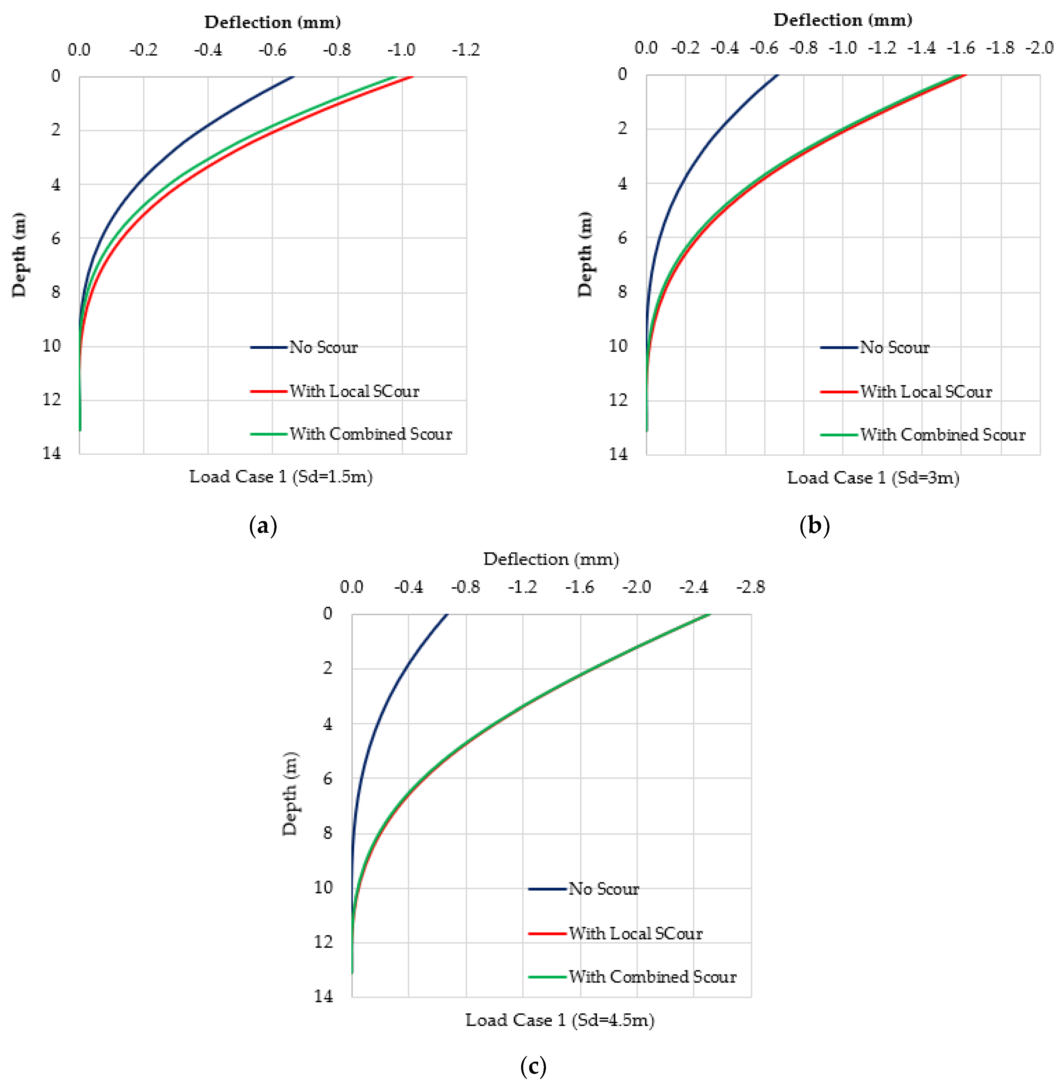
For the load case scenarios assessed in this study, the pile head (ground level) deflection increases exponentially from 55% to 278% for local scour depths ranging from a 1.5 m to 5 m depth. This, again, was deemed critical to the long-term performance of the bridge.
When comparing local and combined scours, the combined scour only increased the average bending moments from the local scour cases by an additional 5–6% (worst case scenario), and, hence, is deemed not significant for contributing to the increase in bending moments.
The conventional design of bridges with piers-on-bank foundations usually ignores the potential for significant scouring problems. Using the Phillips Road bridge as a case study, we demonstrated that an unmanaged scour problem can result in a significant increase in the lateral displacement of the pier head and bending moments, even for piers-on-bank bridges. Hence, timely preventive measures are needed to rectify the scour problem at the initial stage of local scour development in order to avoid the further widening of scour holes resulting in the weakening of the bridge support.
While the last observation shows limited effects from the combined scour case to the Phillips Road bridge foundation, this can be due to the close spacing between the bridge piers. Further studies should be conducted to determine if the effects of combined scour can be worsened with wider bridge pier spacings.


 ,
, 


