
Alkali Iodide Deep Eutectic Solvents as Alternative Electrolytes for Dye Sensitized Solar Cells


Abstract
1. Introduction
- (1)
- the first one, comprises an aqueous electrolyte (15 wt%) based on choline iodide and glycerol (ChI:Gly) as eutectic mixture (solid at room temperature) as part of the electrolyte composition for DSSCs. Ref. [43] The reported electrolyte contains 0.2 M of iodine (I2), 0.5 M of N-methylbenzimidazole in a mixture of 1-propyl-3-methylimidazolium iodide ([PMIM]I) and the prepared binary mixture (v/v, 13:7). The selected sensitizer dye was the metal-free indoline dye D149, because it is more suitably mixed with the highly viscous electrolyte. The reported DSSCs showed an open circuit voltage (VOC) of 0.533 V, short circuit current density (Jsc) of 12.0 mA·cm−2, a fill factor of 0.582 and 3.88% of energy conversion efficiency under AM 1.5, 100 mW/cm2 illuminations [43];
- (2)
- a similar approach using an aqueous electrolyte (40% w/w water content) that was composed by choline chloride and glycerol eutectic mixtures (ChCl/Gly, 1:2 mol/mol) as an effective electrolyte solvent for DSSCs have been reported. Ref. [44] The selected sensitizer dye corresponds to the hydrophilic PTZ-TEG dye. The authors reported that the best DSSCs performance was obtained using a 2 M of 1-propyl-3-methylimidazolium iodide ([PMIM]I), 0.1 M of guanidinium thiocyanate (GuSCN) in a 40% aqueous solution of ChCl:Gly. In this case, the DSSCs showed VOC of 0.504 V, JSC of 5.1 mA·cm−2, FF of 0.66, and an overall power conversion efficiency (PCE) of 1.7%;
- (3)
- later, the same authors reported a hydrophobic eutectic solvent composed by DL-menthol and acetic acid as an eco-friendly passive electrolyte medium for DSSCs [45]; and,
- (4)
- more recently, natural deep eutectic solvents (NADES) as effective electrolyte solutions for DSSCs have been also reported. Ref. [46] These aqueous (20–30 wt%) NADES are composed by sugars (e.g., Glucose, Sorbitol, Fructose, and mannose) and choline chloride (ChCl). The authors investigated the potential active involvement of DES media with a selected phenothiazine-based sensitizer, which is composed by a glucose functionality, and a glucose based-co-adsorbent (glucuronic acid) to improve the photovoltaic performance. The reported electrolyte was composed by iodine (20 mM), 2 M [PMIM]I in different aqueous NADESs.
2. Results and Discussion
- (1)
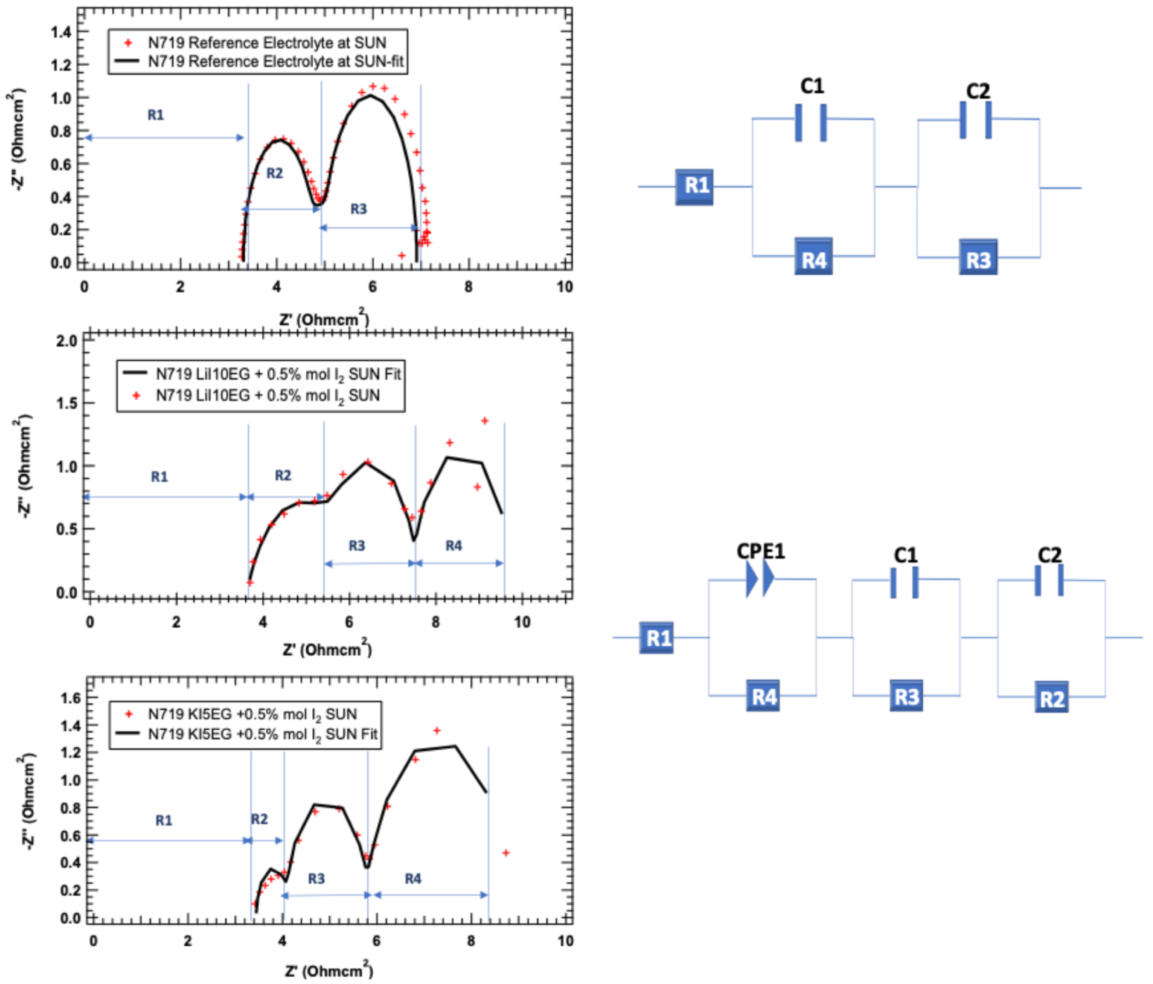
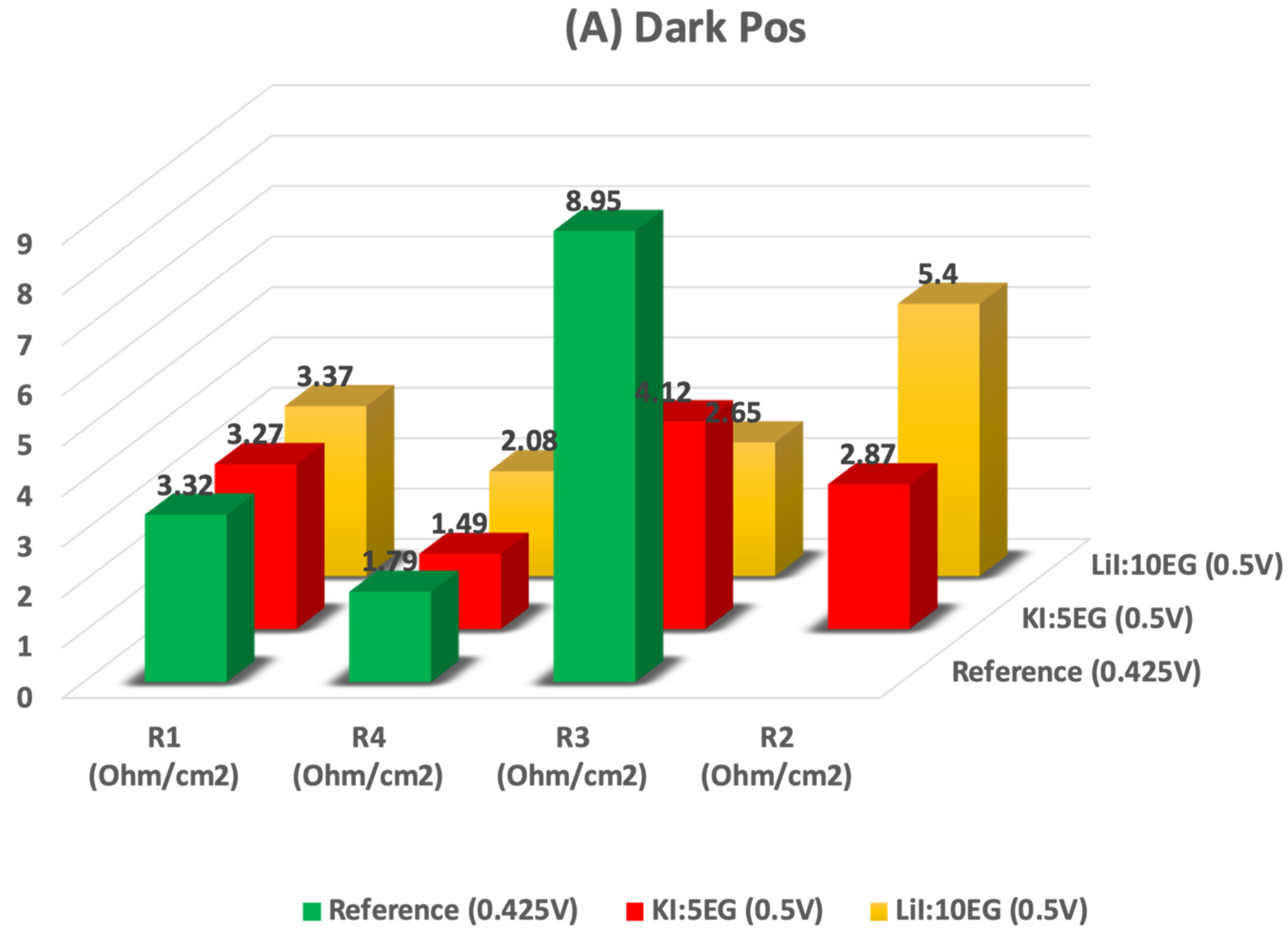
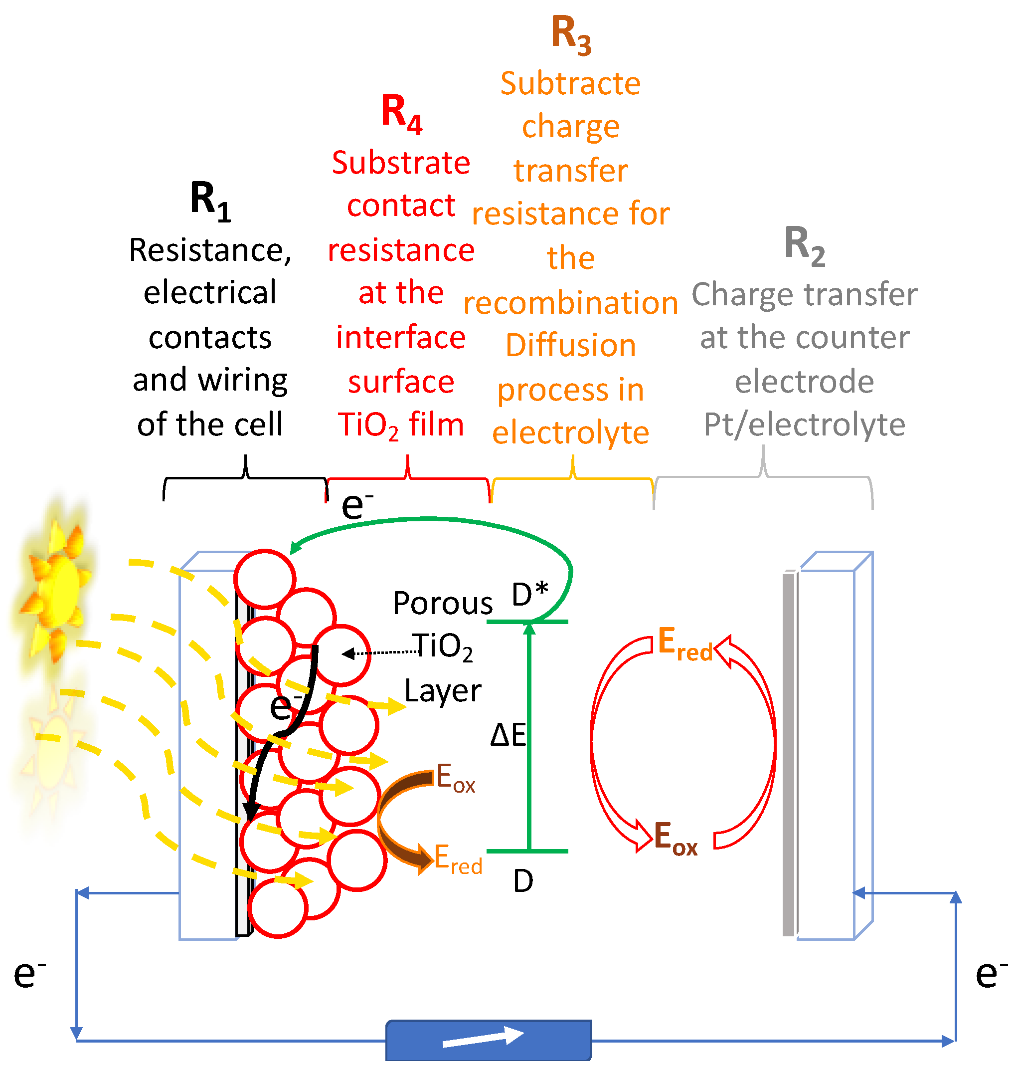
- In the case of R1, the resistance that can be attributed to the materials used, including cables, is almost the same for all electrolytes studied, i.e., the electrolyte does not influence this parameter.
- (2)
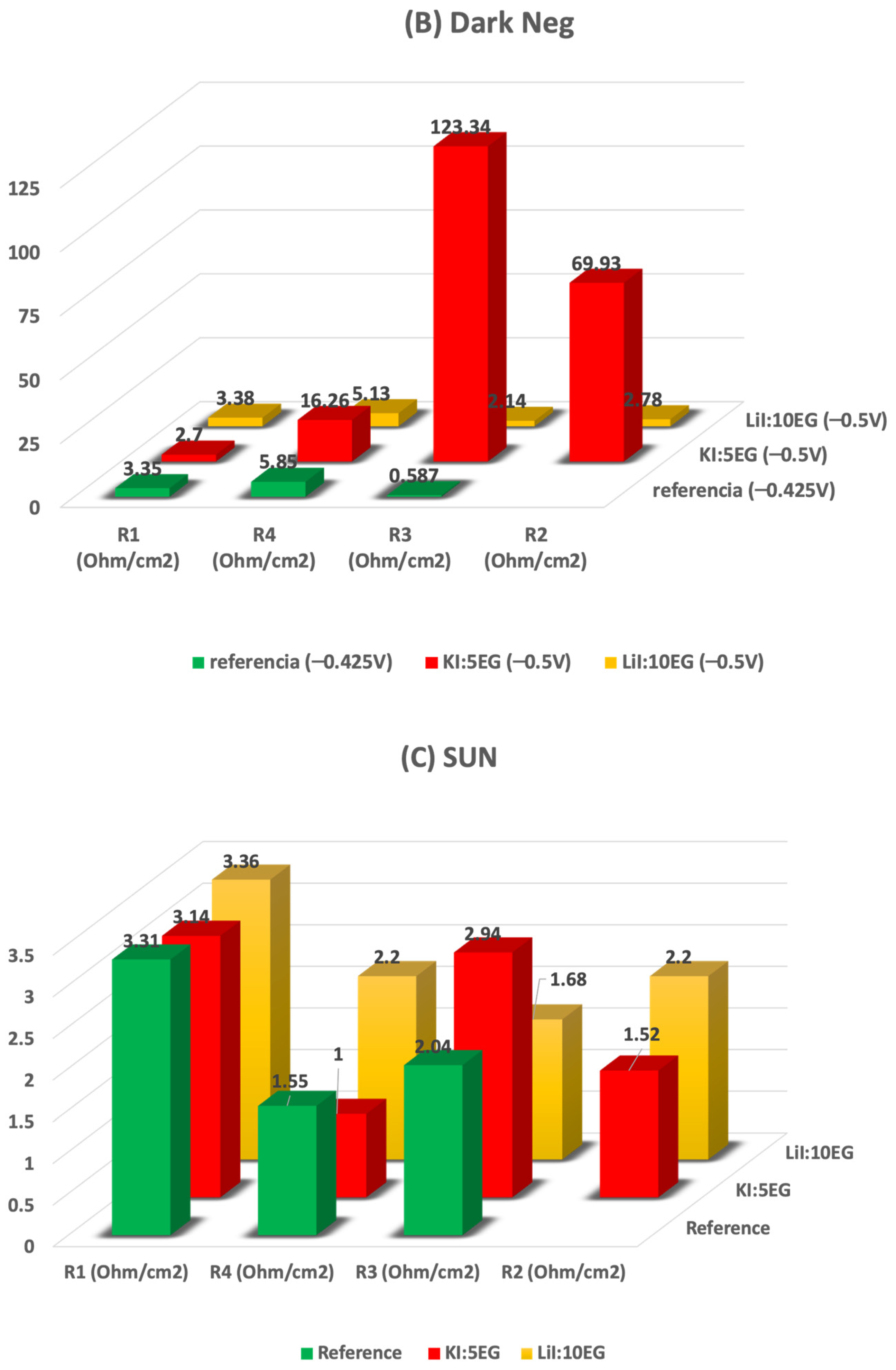
- R2, (above 1 KHz) is related with the resistance to the charge transfer at counter electrode (Pt/electrolyte) interface and redox couple regeneration at the counter-electrode. This phenomenon can be observed in Figure 4, and the following trend for the electrolytes studied was verified: KI:5EG + 0.5 mol% I2 < Reference < LiI:10EG + 0.5 mol% I2. This could be related to the bulkier K+ cation. The cation bulkier radius allows lower resistance to the regeneration of the redox couple. While Li+, a smaller cation, can be more easily found in the vicinity of the electrode and the redox pair stabilizing them, thus increasing the resistance to the regeneration process. This is even more significant in the presence of the EG.
- (3)
- R3 (1 Hz to 1 KHz), associated to the electron transfer process (transport) in the TiO2 layer, the recombination and dye regeneration, LiI:10EG + 0.5 mol% I2 < Reference < KI:5EG + 0.5 mol% I2. In this case, the DES LiI:10EG + 0.5 mol% I2 allows a faster regeneration of the dye, probably due to the amount of Li+ cation that can intercalate with the dye/TiO2 nanomaterial, even when comparing with Reference (lower amounts of Li+). Moreover, in the presence of high concentrations of EG, a strong interaction between Li+:EG might be occurring, leaving the redox pair more available for dye regeneration. The bulkier K+ cation could act as an umbrella, lowering the intercalation process and, consequently, the number of photo-injected electrons on the TiO2 nanomaterial when compared with the Li+ cation, as expected.
- (4)
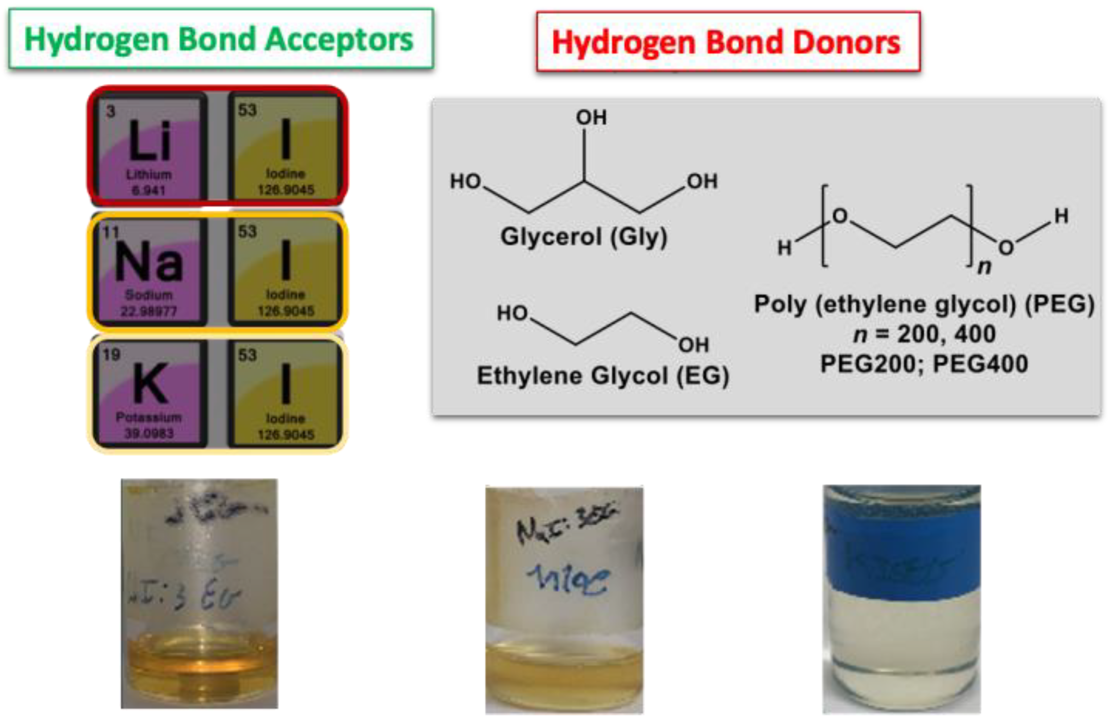
- R4 (<1 Hz), is related to the diffusion of the species into the electrolyte. This particular process and, as expected for a well-studied Reference electrolyte, is so fast that it is not observed in terms of resistance to the process, as in Table 2. This electrolyte allows for a fast diffusion of the species, as can be seen from Figure 4. In the case of the DES based electrolyte KI:5EG + 0.5 mol% I2 < LiI:10EG + 0.5 mol% I2, some unexpected results were obtained. The bulkier K+ cation allows for a better diffusion process then the Li+, a smaller cation in the presence of EG, although being the same cation used in the reference (which presents no resistance to the diffusion process). Additionally, increasing the amount of EG from K+ to Li+ should lower the viscosity, thus increasing the diffusion process, which is the opposite of what was experimentally observed. This could be related with the formation of LiI:10EG + 0.5 mol% I2 by the self-complexation (Hydrogen bonds (HB) between the iodide and the alcohol of the Ethylene Glycol) leaving the Li+ relatively free. R4 (<1 Hz) is related to the diffusion of the species into the electrolyte. This particular process and, as expected for a well-studied Reference electrolyte, is so fast that it is not observed in terms of resistance to the process, as shown in Table 2. This electrolyte allows for a fast diffusion of the species, as can be seen from Figure 4. In the case of the DES based electrolyte KI:5EG + 0.5 mol% I2 < LiI:10EG + 0.5 mol% I2 some unexpected results were obtained. The bulkier K+ cation allows a better diffusion process then when the Li+, a smaller cation in the presence of EG, despite being the same cation used in the reference (which presents no resistance to the diffusion process). Additionally, increasing the amount of EG from K+ to Li+ should lower the viscosity thus increasing the diffusion process, which is the opposite of what was experimentally observed. This could be related with the formation of LiI:10EG + 0.5 mol% I2 by the self-complexation (Hydrogen bonds [HB] between the iodide and the alcohol of the Ethylene Glycol) leaving the Li+ relatively free.
3. Experimental
3.1. Chemicals
3.2. Synthesis of DES
3.3. Electrochemical Measurements
3-electrode Configuration Cyclic Voltammetry
3.4. Electrochemical Impedance Spectroscopy (EIS)
3.5. DSSCs Fabrication and Photovoltaic Characterization
3.6. Photoelectrochemical Measurements
4. Conclusions
Author Contributions
Funding
Institutional Review Board Statement
Informed Consent Statement
Data Availability Statement
Acknowledgments
Conflicts of Interest
References
- Armaroli, N.; Balzani, V. Solar Electricity and Solar Fuels: Status and Perspectives in the Context of the Energy Transition. Chem. A Eur. J. 2016, 22, 32–57. [Google Scholar] [CrossRef] [PubMed]
- Su’Ait, M.; Rahman, M.; Ahmad, A. Review on polymer electrolyte in dye-sensitized solar cells (DSSCs). Sol. Energy 2015, 115, 452–470. [Google Scholar] [CrossRef]
- Susanti, D.; Nafi, M.; Purwaningsih, H.; Fajarin, R.; Kusuma, G.E. The Preparation of Dye Sensitized Solar Cell (DSSC) from TiO2 and Tamarillo Extract. Procedia Chem. 2014, 9, 3–10. [Google Scholar] [CrossRef]
- O’Regan, B.; Grätzel, M.; Gr, M. A low-cost, high-efficiency solar cell based on dye-sensitized colloidal TiO2 films. Nature 1991, 353, 737–740. [Google Scholar] [CrossRef]
- Hagberg, D.P.; Yum, J.-H.; Lee, H.; De Angelis, F.; Marinado, T.; Karlsson, K.M.; Humphry-Baker, R.; Sun, L.; Hagfeldt, A.; Grätzel, M.; et al. Molecular Engineering of Organic Sensitizers for Dye-Sensitized Solar Cell Applications. J. Am. Chem. Soc. 2008, 130, 6259–6266. [Google Scholar] [CrossRef] [PubMed]
- Grätzel, M. Photoelectrochemical cells. Nature 2001, 414, 338–344. [Google Scholar] [CrossRef] [PubMed]
- Grätzel, M. Solar Energy Conversion by Dye-Sensitized Photovoltaic Cells. Inorg. Chem. 2005, 44, 6841–6851. [Google Scholar] [CrossRef] [PubMed]
- Nazeeruddin, M.K.; Liska, P.; Moser, J.; Vlachopoulos, N.; Grätzel, M. Conversion of Light into Electricity with Trinuclear Ru-thenium Complexes Adsorbed on Textured TiO, Film. Helv. Chim. Acta 1990, 73, 1788–1803. [Google Scholar] [CrossRef]
- Wang, Q.; Moser, A.J.-E.; Grätzel, M. Electrochemical Impedance Spectroscopic Analysis of Dye-Sensitized Solar Cells. J. Phys. Chem. B 2005, 109, 14945–14953. [Google Scholar] [CrossRef]
- Higashino, T.; Imahori, H. Porphyrins as excellent dyes for dye-sensitized solar cells: Recent developments and insights. Dalton Trans. 2014, 44, 448–463. [Google Scholar] [CrossRef]
- Kay, A.; Graetzel, M. Artificial photosynthesis. 1. Photosensitization of titania solar cells with chlorophyll derivatives and related natural porphyrins. J. Phys. Chem. 1993, 97, 6272–6277. [Google Scholar] [CrossRef]
- Campbell, W.M.; Jolley, K.W.; Wagner, P.; Wagner, K.; Walsh, P.J.; Gordon, K.C.; Schmidt-Mende, L.; Nazeeruddin, M.K.; Wang, Q.; Grätzel, M.; et al. Highly Efficient Porphyrin Sensitizers for Dye-Sensitized Solar Cells. J. Phys. Chem. C 2007, 111, 11760–11762. [Google Scholar] [CrossRef]
- Cherepy, N.J.; Smestad, G.P.; Grätzel, A.M.; Zhang, J.Z. Ultrafast Electron Injection: Implications for a Photoelectrochemical Cell Utilizing an Anthocyanin Dye-Sensitized TiO2 Nanocrystalline Electrode. J. Phys. Chem. B 1997, 101, 9342–9351. [Google Scholar] [CrossRef]
- Calogero, G.; Di Marco, G.; Caramori, S.; Cazzanti, S.; Argazzi, R.; Bignozzi, C.A. Natural dye senstizers for photoelectrochemical cells. Energy Environ. Sci. 2009, 2, 1162–1172. [Google Scholar] [CrossRef]
- Calogero, G.; Yum, J.-H.; Sinopoli, A.; Di Marco, G.; Grätzel, M.; Nazeeruddin, M.K. Anthocyanins and betalains as light-harvesting pigments for dye-sensitized solar cells. Sol. Energy 2012, 86, 1563–1575. [Google Scholar] [CrossRef]
- Calogero, G.; Sinopoli, A.; Citro, I.; Di Marco, G.; Petrov, V.; Diniz, A.M.; Parola, A.J.; Pina, F. Synthetic analogues of anthocyanins as sensitizers for dye-sensitized solar cells. Photochem. Photobiol. Sci. 2013, 12, 883–894. [Google Scholar] [CrossRef]
- Calogero, G.; Bartolotta, A.; Di Marco, G.; Di Carlo, A.; Bonaccorso, F. Vegetable-based dye-sensitized solar cells. Chem. Soc. Rev. 2015, 44, 3244–3294. [Google Scholar] [CrossRef]
- Pinto, A.L.; Cruz, L.; Gomes, V.; Cruz, H.; Calogero, G.; De Freitas, V.; Pina, F.; Parola, A.J.; Lima, J.C. Catechol versus carboxyl linkage impact on DSSC performance of synthetic pyranoflavylium salts. Dye. Pigment. 2019, 170, 107577. [Google Scholar] [CrossRef]
- Santra, P.K.; Kamat, P.V. Mn-Doped Quantum Dot Sensitized Solar Cells: A Strategy to Boost Efficiency over 5%. J. Am. Chem. Soc. 2012, 134, 2508–2511. [Google Scholar] [CrossRef]
- Jeon, N.J.; Noh, J.H.; Yang, W.S.; Kim, Y.C.; Ryu, S.; Seo, J.; Seok, S.I. Compositional engineering of perovskite materials for high-performance solar cells. Nat. Cell Biol. 2015, 517, 476–480. [Google Scholar] [CrossRef] [PubMed]
- Gao, P.; Grätzel, M.; Nazeeruddin, M.K. Organohalide lead perovskites for photovoltaic applications. Energy Environ. Sci. 2014, 7, 2448–2463. [Google Scholar] [CrossRef]
- He, M.; Zheng, D.; Wang, M.; Lin, C.; Lin, Z. High efficiency perovskite solar cells: From complex nanostructure to planar heterojunction. J. Mater. Chem. A 2014, 2, 5994–6003. [Google Scholar] [CrossRef]
- Law, C.; Pathirana, S.C.; Li, X.; Anderson, A.Y.; Barnes, P.R.F.; Listorti, A.; Ghaddar, T.H.; O′regan, B.C. Water-Based Electrolytes for Dye-Sensitized Solar Cells. Adv. Mater. 2010, 22, 4505–4509. [Google Scholar] [CrossRef]
- Mahmood, A. Recent research progress on quasi-solid-state electrolytes for dye-sensitized solar cells. J. Energy Chem. 2015, 24, 686–692. [Google Scholar] [CrossRef]
- Mishra, A.; Fischer, M.K.R.; Bäuerle, P. Metal-Free Organic Dyes for Dye-Sensitized Solar Cells: From Structure: Property Relationships to Design Rules. Angew. Chem. Int. Ed. 2009, 48, 2474–2499. [Google Scholar] [CrossRef] [PubMed]
- Abbott, A.P.; Capper, G.; Davies, D.L.; Rasheed, R.K. Ionic Liquid Analogues Formed from Hydrated Metal Salts. Chem. A Eur. J. 2004, 10, 3769–3774. [Google Scholar] [CrossRef] [PubMed]
- Smith, E.L.; Abbott, A.P.; Ryder, K.S. Deep Eutectic Solvents (DESs) and Their Applications. Chem. Rev. 2014, 114, 11060–11082. [Google Scholar] [CrossRef]
- Yang, Q.; Zhang, Z.; Sun, X.-G.; Hu, Y.-S.; Xing, H.; Dai, S. Ionic liquids and derived materials for lithium and sodium batteries. Chem. Soc. Rev. 2018, 47, 2020–2064. [Google Scholar] [CrossRef] [PubMed]
- Sakita, A.M.P.; Della Noce, R.; Fugivara, C.S.; Benedetti, A.V. On the cobalt and cobalt oxide electrodeposition from a glyceline deep eutectic solvent. Phys. Chem. Chem. Phys. 2016, 18, 25048–25057. [Google Scholar] [CrossRef] [PubMed]
- Miller, M.A.; Wainright, J.S.; Savinell, R.F. Iron Electrodeposition in a Deep Eutectic Solvent for Flow Batteries. J. Electrochem. Soc. 2017, 164, A796–A803. [Google Scholar] [CrossRef]
- Mondal, D.; Sharma, M.; Wang, C.-H.; Lin, Y.-C.; Huang, H.-C.; Saha, A.; Nataraj, S.K.; Prasad, K. Deep eutectic solvent promoted one step sustainable conversion of fresh seaweed biomass to functionalized graphene as a potential electrocatalyst. Green Chem. 2016, 18, 2819–2826. [Google Scholar] [CrossRef]
- Bhatt, J.; Mondal, D.; Bhojani, G.; Chatterjee, S.; Prasad, K. Preparation of bio-deep eutectic solvent triggered cephalopod shaped silver chloride-DNA hybrid material having antibacterial and bactericidal activity. Mater. Sci. Eng. C 2015, 56, 125–131. [Google Scholar] [CrossRef] [PubMed]
- Mukesh, C.; Gupta, R.; Srivastava, D.N.; Nataraj, S.K.; Prasad, K. Preparation of a natural deep eutectic solvent mediated self polymerized highly flexible transparent gel having super capacitive behaviour. RSC Adv. 2016, 6, 28586–28592. [Google Scholar] [CrossRef]
- Chakrabarti, M.H.; Mjalli, F.S.; AlNashef, I.M.; Hashim, M.A.; Hussain, M.A.; Bahadori, L.; Low, C.T.J. Prospects of applying ionic liquids and deep eutectic solvents for renewable energy storage by means of redox flow batteries. Renew. Sustain. Energy Rev. 2014, 30, 254–270. [Google Scholar] [CrossRef]
- Zhang, C.; Ding, Y.; Zhang, L.; Wang, X.; Zhao, Y.; Zhang, X.; Yu, G. A Sustainable Redox-Flow Battery with an Aluminum-Based, Deep-Eutectic-Solvent Anolyte. Angew. Chem. Int. Ed. 2017, 56, 7454–7459. [Google Scholar] [CrossRef] [PubMed]
- Liu, P.; Hao, J.-W.; Mo, L.-P.; Zhang, Z.-H. Recent advances in the application of deep eutectic solvents as sustainable media as well as catalysts in organic reactions. RSC Adv. 2015, 5, 48675–48704. [Google Scholar] [CrossRef]
- Parnham, E.R.; Morris, R.E. Ionothermal Synthesis of Zeolites, Metal–Organic Frameworks, and Inorganic–Organic Hybrids. Accounts Chem. Res. 2007, 40, 1005–1013. [Google Scholar] [CrossRef] [PubMed]
- Carriazo, D.; Serrano, M.C.; Gutiérrez, M.C.; Ferrer, M.L.; Del Monte, F. Deep-eutectic solvents playing multiple roles in the synthesis of polymers and related materials. Chem. Soc. Rev. 2012, 41, 4996–5014. [Google Scholar] [CrossRef] [PubMed]
- Cruz, H.; Jordão, N.; Branco, L.C. Deep eutectic solvents (DESs) as low-cost and green electrolytes for electrochromic devices. Green Chem. 2017, 19, 1653–1658. [Google Scholar] [CrossRef]
- Cruz, H.; Jordão, N.; Amorim, P.; Dionísio, M.; Branco, L.C. Deep Eutectic Solvents as Suitable Electrolytes for Electrochromic Devices. ACS Sustain. Chem. Eng. 2017, 6, 2240–2249. [Google Scholar] [CrossRef]
- Jordão, N.; Cruz, H.; Pina, F.; Branco, L.C. Studies of bipyridinium ionic liquids and deep eutectic solvents as electrolytes for electrochromic devices. Electrochim. Acta 2018, 283, 718–726. [Google Scholar] [CrossRef]
- Cruz, H.; Jordão, N.; Dionísio, M.; Pina, F.; Branco, L.C. Intrinsically Electrochromic Deep Eutectic Solvents. ChemistrySelect 2019, 4, 1530–1534. [Google Scholar] [CrossRef]
- Jhong, H.-R.; Wong, D.S.-H.; Wan, C.-C.; Wang, Y.-Y.; Wei, T.-C. A novel deep eutectic solvent-based ionic liquid used as electrolyte for dye-sensitized solar cells. Electrochem. Commun. 2009, 11, 209–211. [Google Scholar] [CrossRef]
- Boldrini, C.L.; Manfredi, N.; Perna, F.M.; Trifiletti, V.; Capriati, V.; Abbotto, A. Dye-Sensitized Solar Cells that use an Aqueous Choline Chloride-Based Deep Eutectic Solvent as Effective Electrolyte Solution. Energy Technol. 2017, 5, 345–353. [Google Scholar] [CrossRef]
- Boldrini, C.L.; Manfredi, N.; Perna, F.M.; Capriati, V.; Abbotto, A. Designing Eco-Sustainable Dye-Sensitized Solar Cells by the Use of a Menthol-Based Hydrophobic Eutectic Solvent as an Effective Electrolyte Medium. Chem. Eur. J. 2018, 24, 17656–17659. [Google Scholar] [CrossRef] [PubMed]
- Boldrini, C.L.; Manfredi, N.; Perna, F.M.; Capriati, V.; Abbotto, A. Eco-Friendly Sugar-Based Natural Deep Eutectic Solvents as Effective Electrolyte Solutions for Dye-Sensitized Solar Cells. ChemElectroChem 2020, 7, 1707–1712. [Google Scholar] [CrossRef]
- Jennings, J.R.; Wang, Q. Influence of Lithium Ion Concentration on Electron Injection, Transport, and Recombination in Dye-Sensitized Solar Cells. J. Phys. Chem. C 2009, 114, 1715–1724. [Google Scholar] [CrossRef]
- Jiang, K.; Yanagida, S. Optimization of Redox Mediators and Electrolytes. In Dye-Sensitized Solar Cells; Kalyanasundaram, K., Ed.; EPFL Press: Lausanne, Switzerland, 2010; p. 117. [Google Scholar]
- Barnes, P.R.F.; Anderson, A.Y.; Juozapavicius, M.; Liu, L.; Liu, X.; Palomares, E.; Forneli, A.; O’Regan, B.C. Factors controlling charge recombination under dark and light conditions in dye sensitised solar cells. Phys. Chem. Chem. Phys. 2011, 13, 3547. [Google Scholar] [CrossRef]
- Cruz, H.; Jordao, N.; Pinto, A.L.; Dionisio, M.; Neves, L.A.; Branco, L.C. Alkaline Iodide-Based Deep Eutectic Solvents for Electrochemical Applications. ACS Sustain. Chem. Eng. 2020, 8, 10653–10663. [Google Scholar] [CrossRef]
- Cruz, H.; Pinto, A.L.; Lima, J.C.; Branco, L.C.; Gago, S. Application of polyoxometalate-ionic liquids (POM-ILs) in dye-sensitized solar cells (DSSCs). Mater. Lett. X 2020, 6, 100033. [Google Scholar] [CrossRef]


| Electrolyte | VOC (mV) | JSC (mA/cm2) | Vmax (mV) | Jmax (mA/cm2) | FF | η (%) |
|---|---|---|---|---|---|---|
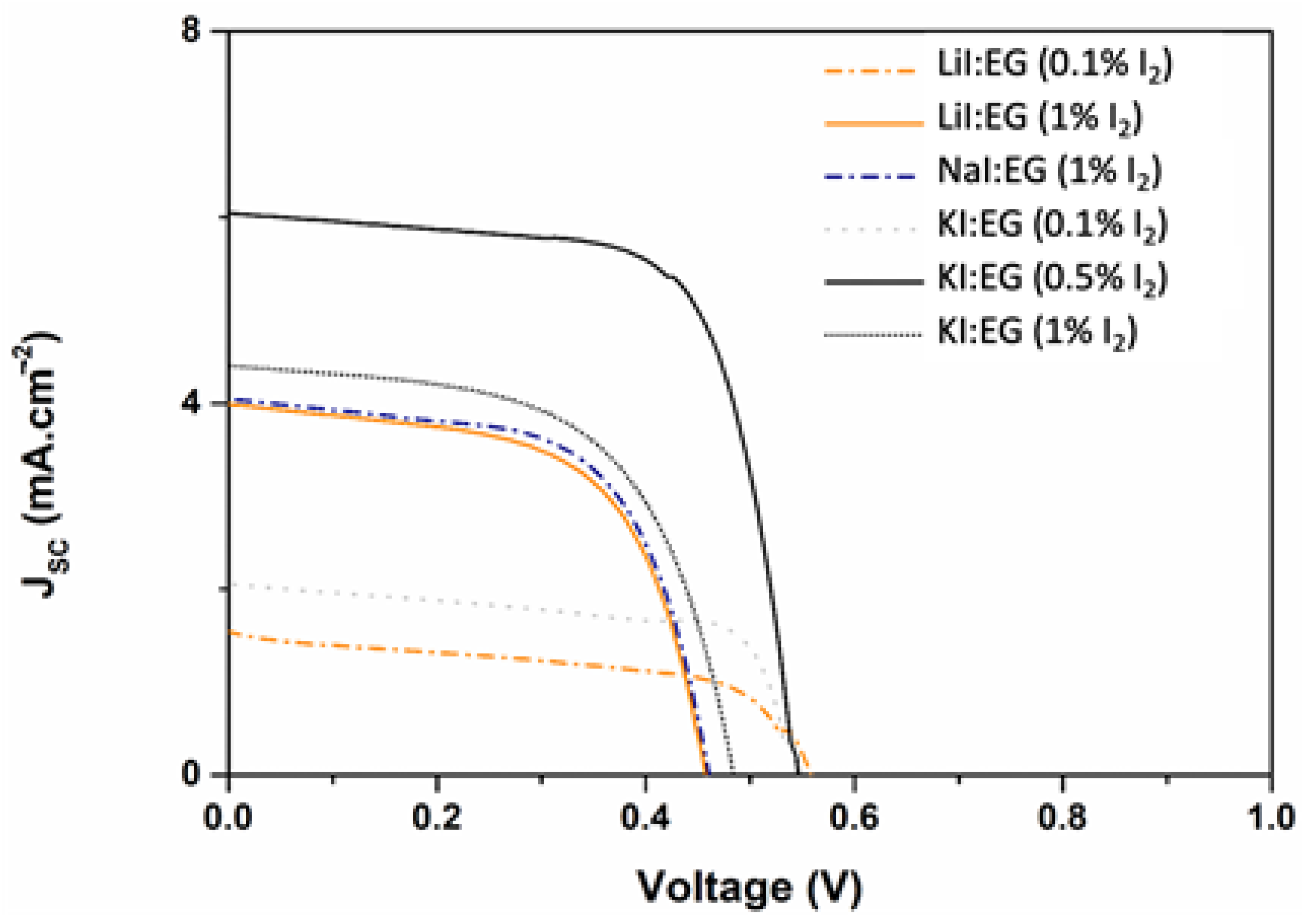
| LiI:3EG (plus 1 mol% I2) | 457 | 4.00 | 346 | 3.21 | 0.60 | 1.12 |
| NaI:3EG (plus 1 mol% I2) | 460 | 4.05 | 347 | 3.32 | 0.62 | 1.16 |
| KI:5EG (plus 0.1 mol% I2) | 543 | 2.07 | 467 | 1.63 | 0.67 | 0.77 |
| KI:5EG (plus 0.5 mol% I2) | 545 | 6.05 | 433 | 5.26 | 0.69 | 2.30 |
| KI:5EG (plus 1 mol% I2) | 483 | 4.42 | 356 | 3.52 | 0.59 | 1.27 |
| KI:5EG (plus 2.5 mol% I2) | 493 | 3.86 | 367 | 3.06 | 0.59 | 1.14 |
| KI:5EG (plus 10 mol% I2) | 51 | 0.13 | 26 | 0.05 | 0.27 | 0.00 |
| LiI:10EG (plus 0.5 mol% I2) | 572 | 4.50 | 446 | 3.57 | 0.62 | 1.61 |
| LiI:10EG (plus 1 mol% I2) | 560 | 4.42 | 427 | 3.57 | 0.62 | 1.55 |
| Electrolyte | Potential [(V)] | Resistance (Ω·cm2) | |||
|---|---|---|---|---|---|
| R1 | R4 | R3 | R2 | ||
| Reference | SUN | 3.31 | 1.55 | 2.04 | - |
| DARK (−425 mV) | 3.35 | 5.85 | 0.587 | - | |
| DARK (425 mV) | 3.32 | 1.79 | 8.95 | - | |
| KI:5EG + 0.5 mol% I2 | SUN | 3.14 | 1.00 | 2.94 | 1.52 |
| DARK (−500 mV) | 2.70 | 16.26 | 123.34 | 69.93 | |
| DARK (500 mV) | 3.27 | 1.49 | 4.12 | 2.87 | |
| LiI:10EG + 0.5 mol% I2 | SUN | 3.36 | 2.20 | 1.68 | 2.20 |
| DARK (−500 mV) | 3.38 | 5.13 | 2.14 | 2.78 | |
| DARK (500 mV) | 3.37 | 2.08 | 2.65 | 5.40 | |
Publisher’s Note: MDPI stays neutral with regard to jurisdictional claims in published maps and institutional affiliations. |
© 2021 by the authors. Licensee MDPI, Basel, Switzerland. This article is an open access article distributed under the terms and conditions of the Creative Commons Attribution (CC BY) license (https://creativecommons.org/licenses/by/4.0/).
Share and Cite
Cruz, H.; Pinto, A.L.; Jordão, N.; Neves, L.A.; Branco, L.C. Alkali Iodide Deep Eutectic Solvents as Alternative Electrolytes for Dye Sensitized Solar Cells. Sustain. Chem. 2021, 2, 222-236. https://doi.org/10.3390/suschem2020013
Cruz H, Pinto AL, Jordão N, Neves LA, Branco LC. Alkali Iodide Deep Eutectic Solvents as Alternative Electrolytes for Dye Sensitized Solar Cells. Sustainable Chemistry. 2021; 2(2):222-236. https://doi.org/10.3390/suschem2020013
Chicago/Turabian StyleCruz, Hugo, Ana Lucia Pinto, Noémi Jordão, Luísa A. Neves, and Luís C. Branco. 2021. "Alkali Iodide Deep Eutectic Solvents as Alternative Electrolytes for Dye Sensitized Solar Cells" Sustainable Chemistry 2, no. 2: 222-236. https://doi.org/10.3390/suschem2020013
APA StyleCruz, H., Pinto, A. L., Jordão, N., Neves, L. A., & Branco, L. C. (2021). Alkali Iodide Deep Eutectic Solvents as Alternative Electrolytes for Dye Sensitized Solar Cells. Sustainable Chemistry, 2(2), 222-236. https://doi.org/10.3390/suschem2020013