2. Problems of Real-Time Train Control and Monitoring
Real-time train control has been available since the inception of rail transport [
15]. Currently, train movement is almost universally monitored and regulated [
16] primarily through signalling, interlocking, and blocking systems (SIBs). SIBs can perform important tasks such as selecting the direction of travel and determining a safe distance between trains. Train safety depends on defining a safe zone in real time around each train and ensuring that no other trains are within these zones [
17]. A train route on a railway can be viewed as a sequence of track sections. Each track section is shown to be occupied, and the travel time is calculated in the literature. These intermediate values depend on the length, speed, stopping time, and many other factors of the moving train. In rail transport, due to the limited number of track sections and sections, it is advisable to take into account or calculate the time after the train begins moving to its destination. This allows for the assessment of the impact of unexpected train delays on the movement of other trains [
18]. A pressing issue in train traffic management on a section is the need to determine the route sequence and make planning decisions to minimise the impact of delays.
The main goal of automating the centralised dispatch system (CDS) is to improve train schedules and expand the capabilities of station route generation based on them [
19]. At the same time, taking into account train priority, it will be necessary to reduce the mutual influence of train schedules and eliminate various types of interference [
20]. This will minimise train schedule delays [
21].
When operationally managing train traffic on rail transport, it is necessary to consider train routes, track occupancy times, and potential conflict situations [
22]. To this end, alongside expanding the functionality of train dispatcher (DNC) traffic management systems [
23] that manage transportation processes [
24], several mathematical models and algorithmic methods are used to model the process and solve problems [
25]. First, we will examine how a system based on the mathematical theory of blocking time, an alternative graph model, and search algorithms enables the detection and resolution of conflict situations that arise in train traffic [
26].
Train traffic safety involves creating a safe zone around each train and preventing other trains from entering this zone [
8]. Railroad traffic can be viewed as a sequence of sections and segments [
27]. Each section and segment takes a certain amount of time, which depends on the train’s length, speed, stopping time, and other factors [
28]. A key task in traffic management is to minimise the impact of one train’s delays on the movement of others. Mathematical models are used for this purpose, including blocking time theory, the alternative graph model, and the tabu search algorithm [
12,
25]. These methods allow for the identification and resolution of potential traffic conflicts. According to safety requirements, when a train passes through a certain section of track, that section is completely blocked and cannot be used by other trains. Blocking time is defined as the interval from the moment a train occupies the blocking section until it is completely cleared and a safe distance is established. For the mathematical description, the model takes into account additional time intervals:
driver’s perception and reaction time ;
traffic light change time ;
reserve time .
Their sum forms the value of the blocking time for each section in the following Expression (1).
is considered as
To incorporate the above laws into a mathematical model, we use the alternative graph theory. This model is one of the main mathematical models for constructing train schedules. It was first proposed by Mascis and Pacciarelli [
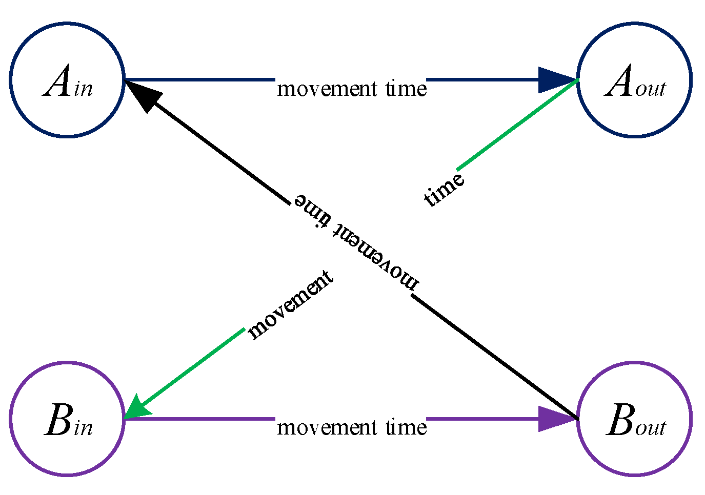
14]. In alternative graph theory, the events of each train entering and leaving a block section are described by a separate graph. The train’s sequential passage through block sections along the route is regulated by directional arcs (arcs reflect the duration of the train’s travel along the block section). If the calculation determines that two or more trains will arrive at a certain section simultaneously, a pair of arcs with opposite directions is added to account for possible conflicts (
Figure 1).
Figure 1.
Alternative graph model.
Figure 1.
Alternative graph model.
where —the event of Trains A and B arriving at the block section, and —the event of Trains A and B leaving the block section. Arcs directed in different directions represent two different options:
- -
In the black directed arc, Train A goes first, and Train B follows;
- -
In the green directed arc, Train B goes first, and Train A follows.
When one of the alternatively directed arcs is selected, the conflict is resolved, and the other directed arc is automatically rejected.
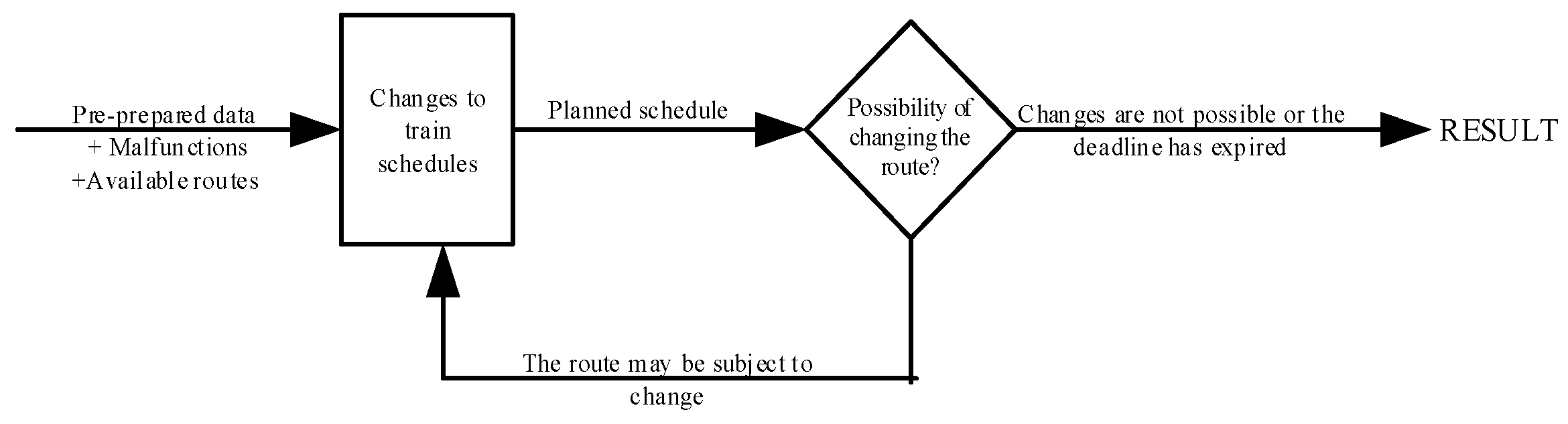
The tabu search algorithm has also been used in scientific research. Tabu search is one of the most common approaches to solving complex problems [
2]. A special search method for rerouting trains has been described in the literature (
Figure 2).
Initially, a planned train schedule is generated. In this case, the selected route is given priority to allow each train to pass through the station without stopping on the main track. The detection algorithm then selects an alternative route for each train. It also rebuilds the new schedule. If the result improves, it accepts it; otherwise, it moves on to another option. The reason for choosing this algorithm is that it includes tried options in a list of prohibited ones, thereby preventing the same solution from being tried twice. As a result, the calculation time is somewhat reduced.
Based on the above, the control problem in a distributed computing system can be expressed as a discrete optimisation problem. The goal is to minimise the longest path length in the graph, i.e., to minimise the longest delay.
Formal model of an automaton
We model the possibilities of installing each available route at a line station (LS), which is a station-level control object that includes switches, signals, and track sections managed as a single interlocking unit using control theory based on finite-state automata. Automata (2) consists of six components. We describe the collection as follows:
where
—a set that defines the state of route objects in the LS (input alphabet);
—multiple memory management;
—set of states of the machine;
—transition function;
—output function; and
—multiple output signals.
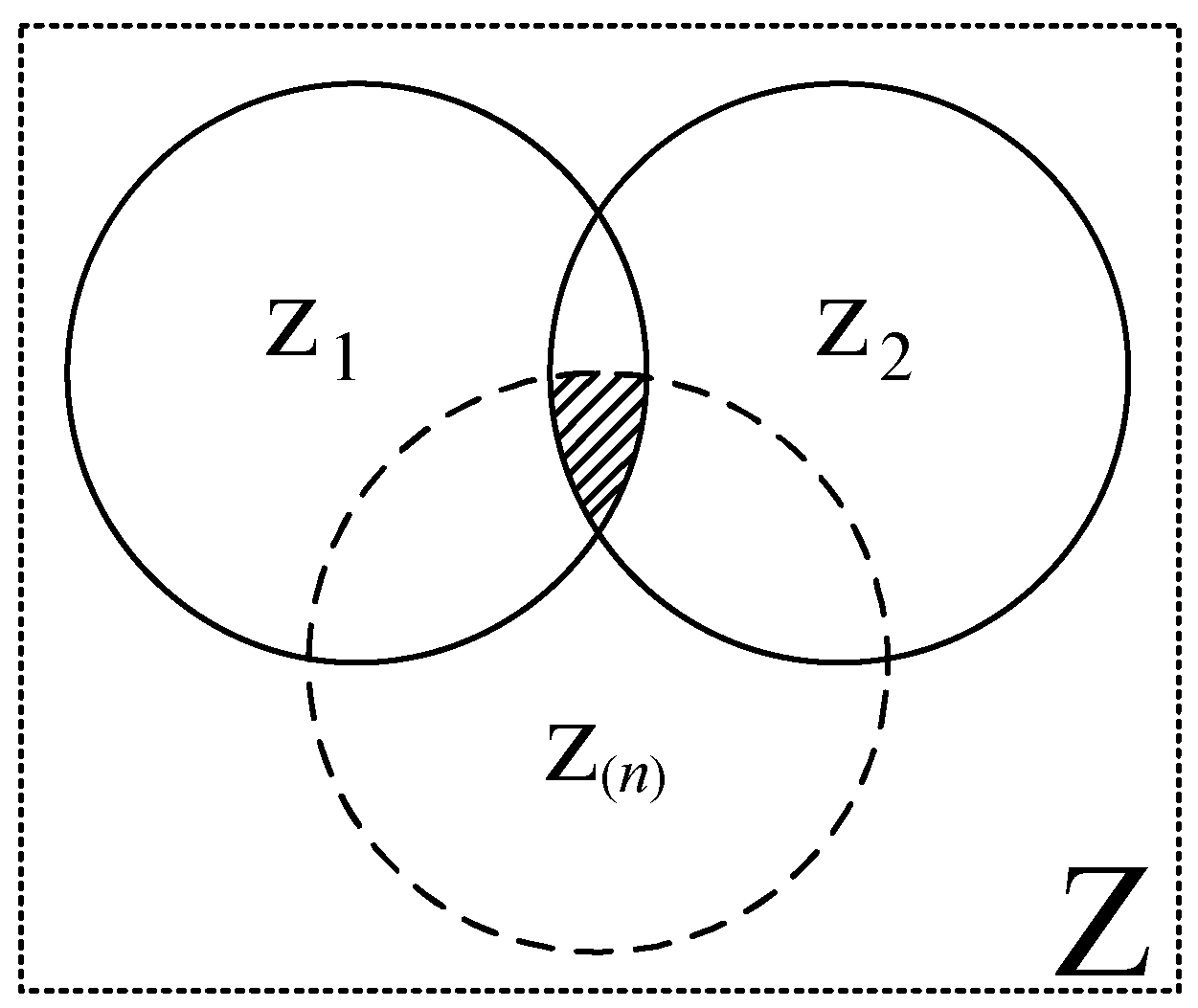
The route structure of the LS includes all information about switches, traffic lights, sections with and without switches, and paths. Z was collected into a set (
Figure 3).
One railroad switch, as well as switch and non-switch sections, may participate in more than one route; this situation is illustrated by the shaded area in
Figure 3.
The route structure of the LS includes all information about railway switches, signals, and sections with railway switches and without switches, as well as tracks. The Z elements are collected into a set.
where
—the state of the railway switch,
—the state of the traffic light, and
—the state of the section and tracks.
A railway switch can be in five possible states (
Table 1).
For the traffic lights, there are mainly two possible states: permissive () and prohibitive ().
Sections and tracks can be in four possible states (
Table 2).
The set of input signals Z represents a collection of discrete tele-signals received from the route objects of the line station and characterising their current physical state, including the occupancy of the railway switch and non-switch sections, the position and control of the railway switches, and the presence or absence of safety violations. These signals form the input alphabet of the Mealy automaton and are used to determine transitions between its states.
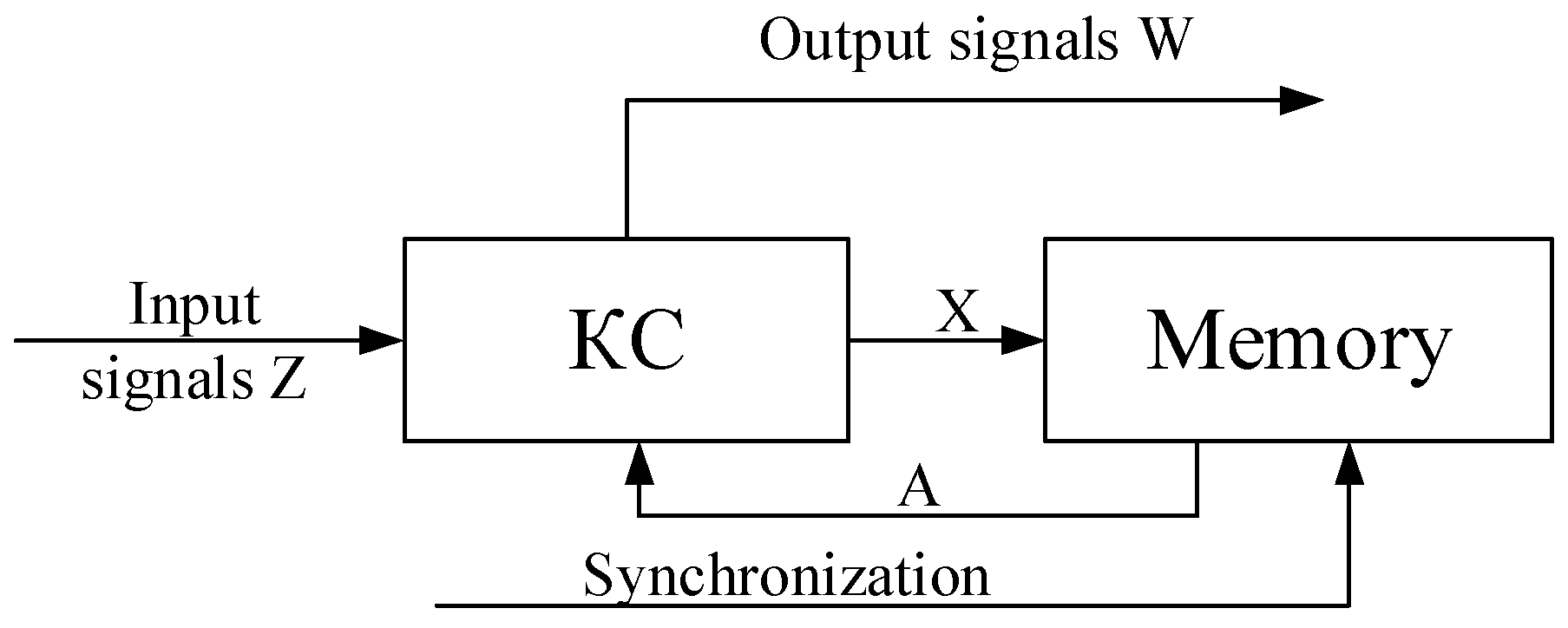
The generalised structural diagram of automaton C is shown in
Figure 4.
In
Figure 4, the automaton C consists of two functional blocks. The combinational circuit (KC) generates the automaton’s output signal and the memory control signal. The automaton memory is represented by a set of flip-flops.
When constructing a route, the state of the LS also depends on events occurring at the object. Since the output signal is directly related to the current input signal and state, we use a Mealy machine, given its ability to respond quickly. According to the Mealy machine, the transition and output functions are expressed as follows:
The set of states of machine
Let us take a closer look. The main goal is to express combinations of previously established/unestablished routes and their compliance with safety requirements as formal cases for selected route segments. Within this model, we identify four main cases and describe them as shown in
Table 3.
We create a transition table and output function for the machine (
Table 4):
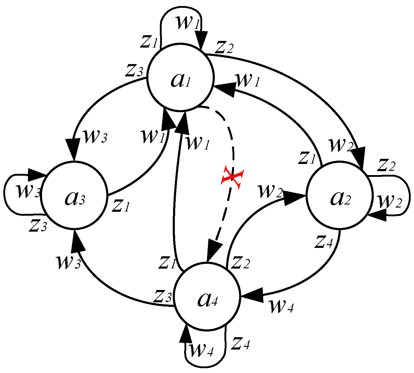
Using
Table 4, a graphical representation of the machine shown in
Figure 5 is provided.
The graph shows four states and transitions between them. The initial state is considered. If the route is specified in the LP, the machine makes a transition to the state . On the other hand, if a section of the route becomes occupied without any route being established or one of the switches involved in the route loses control, the machine goes into the state . Technically, switch or non-switch sections will not be blocked, and a section will not be occupied without a route established. In this model of the machine, the condition determines the impossibility of a direct transition from the state to the state When the route is set and the train begins to sequentially occupy block sections, the machine makes a transition to the state , which reflects the formalisation of the route occupation process in the model. After the section is vacated by a train, the machine, in accordance with the adopted route release scheme, performs a transition, in the case of a route release, to the state , and when opened separately, to the state , which ensures the formalisation of the process of returning the system to an acceptable state. Thus, the Mealy automaton model allowed us to formally identify four main states and strictly define the patterns of their transitions. This made it possible to represent the process of preparing a selected route in the centralised dispatch system as a mathematical automaton model, which increases the accuracy and reliability of the analysis. The output signals of the automaton states are interpreted as follows: in state , the signal shows a proceed (permissive) indication, allowing the train to move; in states and , w1 = w3, the signal shows a stop (prohibitive) indication. In state , the prohibitive signal remains on, but the train continues moving along the route.
Integrated Model: Variables and Constraints
Thus, two key components—the alternative graph model, which provides real-time traffic control, and the Mealy automaton, which formalises the logic of tele-signalling (TS) and remote control (RC) signals—are combined into a single integrated mathematical model. In this model, the times of occupation and release of switch and non-switch sections, as well as block sections, are considered as control variables of the dispatcher’s decisions; while the Mealy automaton introduces a system of constraints, the violation of which is excluded due to safety requirements.
Key variables: for each train and each block section,
is the train reservation time for sections with and without switches and block sections on routes, and
is the clearance time. If, before entering block
b, train
t has successively passed through switch or switchless sections or block sections of route
b − 1, a corresponding sequential blocking time is introduced to ensure safety.
where
—represents the time it takes a train to traverse a switch or switchless section or a block section of route
. This inequality formalises the chronological consistency of each train route and ensures the correctness of the time sequence.
According to safety requirements, two trains cannot occupy the same block section at the same time. In the model, this requirement is expressed by choosing alternative edges in the alternatives graph. Formally, if trains
and
have the possibility of conflict on a switch or switchless section or block section of route b, a restriction is imposed in the form of condition (7):
where
—denotes the minimum time interval that must be maintained after train
t leaves a switch or switchless section or a block section of route b until the train enters
. The value of this interval is determined by the blocking time, calculated depending on the characteristics of the components. The above logical “OR” (
) the condition means that initially the train
passes first and
enters it after a specified time interval, or
first and then
. The model can introduce a suitable alternative variable for making this decision and represent both cases by a system of separate linear inequalities (7).
where
is the sequence of trains in a switch or switchless section or block section on route b, and
is a constant. Using the constant
, two alternative constraints are written down, representing a discrete choice, and only one of them becomes “active” depending on the value
. The M value depends on the travel time of trains in a switch or switchless section or block section on route B. The M value is determined by Formula (9):
where
T is a set of trains operating on the section in question, and
B is a multitude of switch and non-switch sections, as well as block sections included in the section under consideration.
As a result, for each pair of these representations, one arc with the opposite direction is selected, which guarantees the absence of cycles in the graph. This constraint constitutes a fundamental part of the train dispatcher’s decisions (DNC)—it is precisely what determines which train will be given priority.
An essential component of the model is the constraints associated with signal states. Their introduction is necessary to ensure compliance with the operating rules of the Mealy machine. The model identifies two main conditions that determine acceptable signal states:
1. Route Setting Condition: For a train to enter a switch or non-switch section or a block section, a route must be established in advance for that section (otherwise, the signal will not display a permissive aspect, and the train will not be able to proceed along the route). In the model, this condition is directly related to the conflict constraints between trains t and t′: if train t proceeds first, it means that before the arrival of train t′, the route for train t has already been established, and the corresponding switch or non-switch section or block section is occupied; otherwise, priority is given to train t′, and train t waits. The decision for the variable is allowed only when the route has been pre-established specifically for train t (state a2). According to the Mealy automaton, granting the train dispatcher permission to set a route for the train corresponds to a transition of the automaton from state a1 to state a2. If the model assigns a time to train t without allocating the corresponding route, this is considered an inadmissible event (transition , which is forbidden), and such a solution is regarded as incorrect. Therefore, in constructing the model, the possibility of a direct transition to state a4 is excluded: the combined action of conflict constraints and route conditions eliminates this option.
2. The condition for the occupancy of a railway switch, switchless section or block section is formulated as follows: after a train enters a given section, until it is vacated, it is impossible to assign another train to pass the corresponding route elements. This condition follows directly from the system of conflicting inequalities: if train t is on route section b, then another train cannot be assigned a time to pass the same section. In the logic of the Mealy machine, this situation corresponds to the state , the duration of which limits the possibility of transition to a state for other trains. In the integrated model, this constraint is guaranteed for all pairs of trains, since for any pair , a time interval D must be observed between the moments of exit and entry, which excludes the possibility of simultaneous entry.
The above conditions are implemented in the integrated model in the form of state constraints formalised using mathematical functions of the automaton and graph constraints. Ultimately, the model combines two key components: (i) directed selection of train movement timing parameters based on an alternative graph approach; (ii) verification of each control command for compliance with safety requirements using Mealy automaton constraints.
The structure of the proposed system
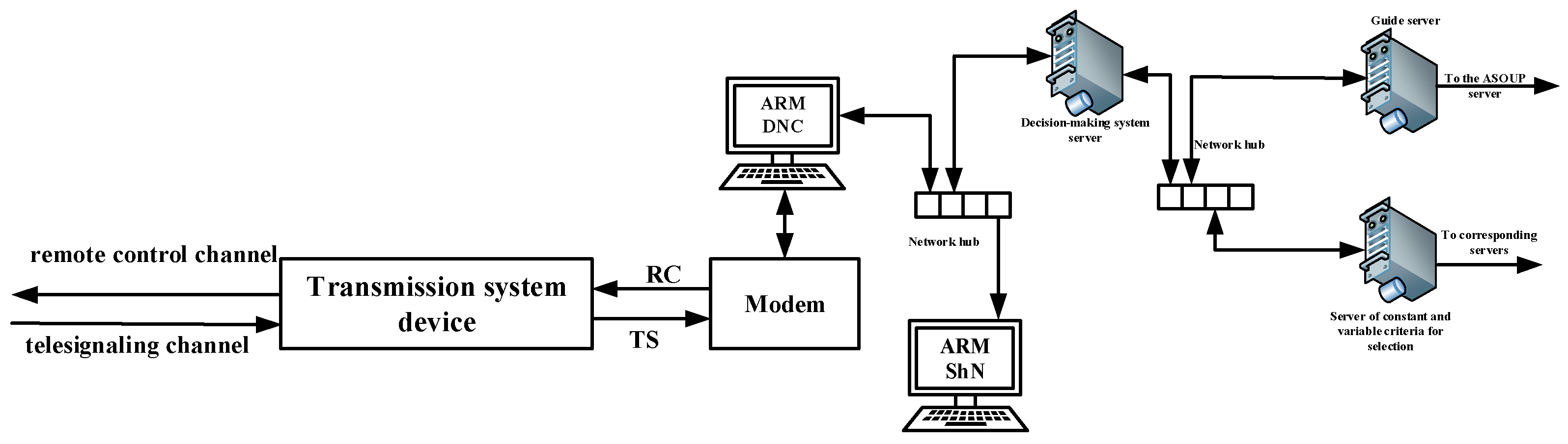
The structural diagram of the system is shown in
Figure 6.
The transmission system device shown in the diagram is part of a complex that provides communication between the central control station (CC) and the line station (LS). The DNC automated control system serves as an interface for monitoring train status along the section and as the central hub for generating control commands. Using signals received via the TS channel, a visual representation of the section status is generated. Information received from the LS is first processed by the DNC automated control system and then made available to the relevant personnel via the local network. It should be noted that the indications displayed on the electromechanical (SHN) control system are identical to those on the DNC automated control system. This enables monitoring of troubleshooting activities at the LS and provides a means for initial technical consultation.
Data on the train number, weight, length, destination, locomotive, and locomotive crew are received from the Train Schedule Server (TSS). This information is essential for determining the category and priority of each train. To support decision-making, additional information is generated by the fixed and variable criteria server, including the track profile, technological windows provided by the relevant companies, trackside warnings, and other operational data. All information affecting train movement is collected in the system’s decision-making server, where a route sequence is generated and transmitted to the DNC automated workstation. After the proposed decision is approved by the DNC, the corresponding command is sent from the DNC automated workstation to the LS via the transmission device and the RC channel.
To ensure reliable information exchange between the LS and the CP, additional communication protocols have been implemented, including packet verification using CRC codes and synchronous response mechanisms. For example, after a command is sent from the CP, the LS acknowledges its receipt and, upon execution, reports the result via the TC channel. The CP also periodically sends synchronous requests (SRs), enabling complete visualisation of the current state of the LS. Upon receiving such a request, the LS PLC aggregates key information (e.g., the occupancy of all track sections and the status of all signals) and transmits it to the CP in the form of an RC signal. Thus, the CP always maintains up-to-date information about the system state. If changes to the operational plan are required (for example, if a train is significantly delayed and track availability must be reassigned), the CP recalculates the solution using the alternative graph model and generates an updated decision. The corresponding sequence of commands is transmitted to the LS, where it is executed using Moore machine logic, ensuring secure and consistent signal exchange.
This centralised automated control forms a closed-loop structure: optimisation algorithm → commands → field devices → measurements → optimisation. As a result, the system adapts rapidly in real time to dynamic changes (such as delays or equipment malfunctions), ensuring safe and efficient traffic management.
Crossing two trains on a single-track section at one station
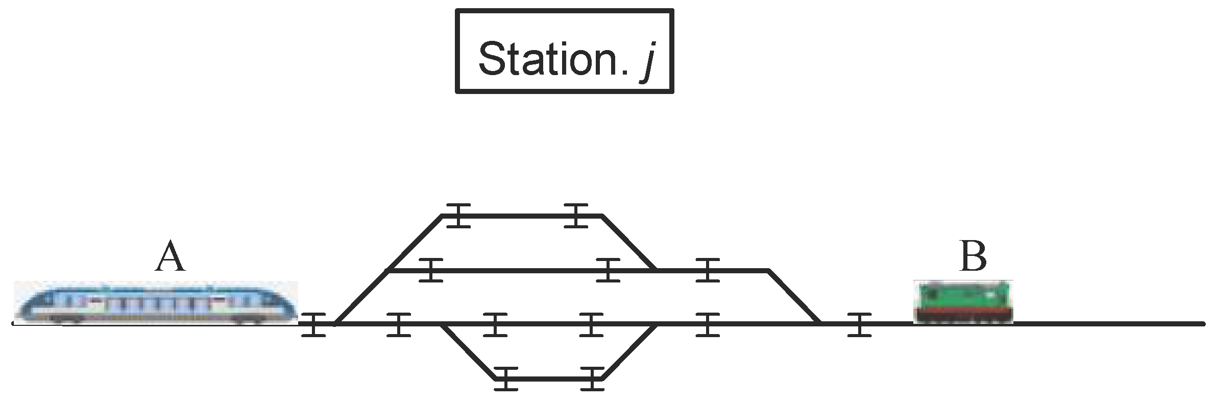
Let us consider a situation where two trains moving towards each other must cross on a single-track section within a station
(see
Figure 7).
There is no established route at the station in question—the system is in a state Within the alternative graph model, the question of which train will be allowed to proceed first is decided. Let us say that priority in the graph is given to Train A, while Train B is designated as waiting. The arrival times of the trains at the station are designated as and and are checked by the condition . The model then automatically imposes the appropriate restrictions. Since Train B is considered waiting, it is accepted onto the side track, while Train A receives priority passage on the main track.
In this case, the Mili A machine is intended for the train.
moves automatically when Train A arrives at the station.
Train A waits on the siding until Train A has fully entered the station. The conflict constraint in Model (8) guarantees exactly this order: Train A cannot depart until Train A has fully entered the station. In this situation, the Mealy automaton for Train A implements the transition to state
, and after Train A enters the station, the transition to the state
Until Train A fully enters the station, Train B is forced to wait on a side track. Conflict constraint (9) built into the model guarantees this order: until Train A is fully cleared, Train B is prevented from exiting:
where
—is the last common section on the route of Train A and the first common section on the route of Train B.
After Train A has cleared section m, the machine on its side at the moment of time returns to state . For Train B, the conflict situation is resolved, and a command to open a route for Train B is transmitted from the central control unit to the central control unit, which causes the automatic control unit on its side to switch to the state . Train B starts moving and, having occupied the first section, switches the machine to the state . Once the section is released, the machine returns to the state . Thus, the integrated model demonstrates an optimal and safe solution: priority for Train A is determined by both safety requirements and the desirability of minimising delays. All commands are exchanged in strict accordance with the rules of the Mealy automaton. If the priority of Trains A and B changes and they cross, for example, at station j, Train A will be accepted onto the main track and wait.
Real-time schedule adjustments when a train is late
Another area of application for the model is dynamic adaptation to deviations from the original schedule. For example, of two trains scheduled to arrive at a station in sequence, one (Train 1) is delayed due to technical issues. According to the original schedule, Train 1 was supposed to enter the station first, with Train 2 following. However, due to the delay, Train 2 arrives earlier. In this situation, the integrated model in the centralised dispatch system promptly recalculates a new solution. According to the alternative graph, swapping the priority between the late Train 1 and the on-time Train 2 minimises delays, allowing Train 2 to proceed first and delaying Train 1 (with minimal impact on other trains). The model generates a route plan for Train 2 (selecting the corresponding alternative arc). As a result, the traffic lights near the station indicate that Train 2 is permitted to proceed. Train 2 passes the station, and then a track is opened for Train 1. The entire process is supported by constant communication with the central control centre: delays are monitored via the TS channel, the alternative schedule model is recalculated, and a decision is made, which is approved by the DNC dispatcher and transmitted via the TU channel. At the line station, the PLC ensures the safe execution of the command. This example demonstrates the ability of the integrated model to support adaptive dispatching decisions in real-world conditions. This ensures the interconnection between planning and control signals, allowing traffic to be organised even when changes occur on the line.
3. Theoretical Justification of the Model’s Stability and Adaptability
The proposed integrated dispatching framework is formulated as a discrete-time dynamic control system (11):
where
—system state (route states, block occupancy, signal configuration);
—control decision (priority selection, route assignment); and
—external disturbance (traffic increase, delay, failure).
To further evaluate the stability and adaptability of the proposed integrated model based on the alternative graph and Mealy automaton, additional computational experiments were conducted under various operational scenarios.
Train intensity on the section is calculated based on the following Expression (12):
If the initial train intensity on the section is assumed to be λ0 = 18 trains/hour and, due to an increase in traffic flow, the intensity rises to λ1 = 25 trains/hour, this condition is considered a high-train-traffic-intensity scenario.
To evaluate delay times, the following time indicators are taken into account (13):
where
—number of trains under analysis (units);
—delay of the i-th train; and
—overall average delay (minutes or seconds).
The delay time is determined using the following Expression (14):
where
—scheduled (planned) time (s or min);
—actual time (s or min).
If only train delays (late arrivals) are taken into account, the expression is written as follows: .
This approach is more commonly used in operational analysis.
In addition, the variance of the delay time is calculated as follows (15):
This indicates the degree of dispersion of train delays within the section: the smaller the value, the more stable the dispatching system operates.
If delays are detected on railway sections due to technical failures or signalling system malfunctions, train movement on the section is reorganised by introducing a rescheduling time parameter (16):
where
—computation time of the algorithm in the k-th scenario (seconds);
—average computation time (seconds).
This indicator evaluates the computational complexity of the train traffic control algorithm and its suitability for real-time operation.
In this case, determining the number of train conflict situations also allows assessment of the safety performance and overall efficiency of the dispatching system (17).
where
—indicator function (equals 1 if a conflict occurs, otherwise 0);
—analysed time interval; and
—total number of conflicts (units).
Taking into account the factors affecting train movement on railway sections, the calculation of the throughput indicator reflects the ability of the dispatching system to operate while considering possible failures (18).
where
—number of trains served;
—time interval (hours); and
—trains/hour.
The probability of safe operation of signalling, interlocking, and blocking systems is determined based on laboratory tests, taking into account the components that constitute the system and their interconnections. The smaller the value of the safety violation probability, the safer the system operates (19).
where
—number of safety rule violation cases;
—total number of examined cases; and
—probability (dimensionless, in the 0–1 interval).
The calculation of the relative improvement (%) of the developed mathematical model demonstrates the efficiency of the proposed model compared to existing models (20).
where
—indicator of the conventional method;
—indicator of the proposed model.
The formal proof of the system stability is established based on the Lyapunov function (21):
If then the system is asymptotically stable. This guarantees the stability of the discrete system. The conducted mathematical modelling, formal proof, and numerical calculation results fully confirm the efficiency, stability, and safety of the proposed integrated (graph + Mealy automaton) model.
Dynamic stability was formally proven based on the Lyapunov function. The satisfaction of the spectral radius condition for the discrete system matrix ensures the asymptotic stability of the system. This theoretically guarantees reliable operation of the model even under high load and failure conditions.
The proposed integrated approach—combining graph theory and the Mealy automaton framework—unifies route planning, conflict resolution, and safety constraint enforcement within a single formal system.
From a theoretical perspective, the model was formulated as a discrete dynamic system, and its stability was proven based on the Lyapunov function. The satisfaction of the spectral radius condition ensures the asymptotic stability of the system. At the same time, by formally incorporating safety constraints into the optimisation problem, it is guaranteed that control decisions are generated outside the “forbidden state space.” This confirms the model’s ability to ensure safety not empirically but on a strict mathematical basis.
The results of numerical calculations and multi-scenario simulations demonstrated the robustness and adaptability of the integrated approach. Even under conditions of high traffic density and system disturbances, stable system operation was observed, along with a significant reduction in delays and a decrease in the number of conflicts. Comparative analysis results showed that the proposed model outperforms conventional and graph-based methods across all key performance indicators.
An important theoretical result is that the integration of automata theory with graph-based resource modelling made it possible to formulate the railway dispatching problem as a constrained discrete optimal control problem. This approach enables the development of a scalable, formally verifiable architecture compatible with digital control platforms.
Thus, the research findings provide a theoretical foundation for developing formal, safe, and efficient models in the field of intelligent railway traffic control. Future research is planned to investigate probabilistic stability analysis considering stochastic disturbances and to optimise computational complexity for large-scale networks.



 ,
,