Article

Exploring a Cost-Effective Approach to AGV Solutions: A Case Study in the Textile Industry


by
Predrag Pecev
1,
Zdravko Ivanković
1,
Vladimir Todorović
2,*,
Marinko Maslarić
3,*,
Sanja Bojić
3 and
Anita Milosavljević
4
1
College of Applied Studies—Sirmium, Zmaj Jovina 29, 22000 Sremska Mitrovica, Serbia
2
Faculty of Project and Innovation Management, Educons University, Bože Jankovića 14, 11010 Belgrade, Serbia
3
Faculty of Technical Sciences, University of Novi Sad, Trg Dositeja Obradovića 6, 21000 Novi Sad, Serbia
4
Technical Faculty “Mihajlo Pupin”, University of Novi Sad, Đure Đakovića BB, 23000 Zrenjanin, Serbia
*
Authors to whom correspondence should be addressed.
Automation 2025, 6(4), 72; https://doi.org/10.3390/automation6040072
Submission received: 5 September 2025 / Revised: 21 October 2025 / Accepted: 3 November 2025 / Published: 10 November 2025

Abstract

This paper explores cost-effective solutions for automated guided vehicle (AGV) through the design and implementation of a low-cost, hoverboard-based line-following AGV tailored for textile manufacturing environments, specifically within sewing plants. The designed AGV leverages the capability of a commercial hoverboard as its mobility platform, significantly reducing development costs while maintaining effective operational performance. Utilizing affordable sensors such as infrared line detectors and ultrasonic sensors, the AGV autonomously navigates pre-defined pathways marked on the factory floor. Its primary function is transporting materials such as fabric bundles and partially or finished products between workstations, addressing common logistical challenges in dynamic and labor-intensive textile production settings. The system is designed for easy integration with both existing plant layouts and information and communication environment, requiring minimal infrastructural changes. Field testing demonstrated the AGV’s reliability, maneuverability, and responsiveness in real-world sewing plant conditions. The proposed solution underscores the potential of retrofitting existing consumer electronics for industrial automation, offering a scalable and economically viable alternative for small- to medium-sized textile enterprises seeking to enhance productivity and workflow efficiency.

1. Introduction

The growing need for automation technologies in manufacturing industries, particularly in labor-intensive sectors, is well recognized. Automation technologies are designed to replace or complement human labour by using machine to perform specific tasks within economic processes [1]. Such technologies help optimize processes, increase efficiency and productivity, and enable higher production volumes while ensuring consistent output quality. Although automation requires an initial capital investment, it can reduce operational costs over time compared to an equivalent human workforce [2].
The textile industry faces challenges such as high market volatility, low predictability, increasing competition and low profit margin due to downward pressure of prices. To address these challenges, textile manufacturer need faster and more flexible production systems, which in turn underscores the necessity for effective operational planning and optimization of a production system [3] using new technologies as well as cost-effective automation solutions. In response to this needs, the present study details the development and deployment of a hoverboard-based, line-following AGV specifically designed for integration into sewing plant operations.
AGVs have emerged as a key enabler for automating internal material handling in many industries and countries [4]. However, off-the shelf AGV system often entail high costs and limited adaptability to industry specific needs. For small and medium-sized (SME) textile manufacturers in particular, investing in standard AGV solutions can be financially prohibitive [5], while the unique layout, product diversity and production dynamics frequently demand customized solutions. Despite the growing interest in automation, there is limited research on developing cost-effective, tailor made AGVs, especially those based on retrofitting existing system and equipment, an approach that can also significantly reduce electronic waste. This paper addresses this gap by exploring a practical approach to designing and implementing customized AGV solutions for the textile industry. The AGV was develop under the research project AGVFlexTex, carried out with support of the DIH–WORLD initiative, for the case company Alpha (the real name of the company has been withheld to maintain confidentiality). Through an in-dept case study, this paper examine how an affordable, adaptable AGV system was conceptualized and integrated in to case company Alpha. The study combines empirical observation, technical evaluation, and engineering prototyping to capture both the design rationale and the practical challenges of development and deployment in a real industrial setting. By highlighting key design considerations and technical implementation, this paper addresses the following main questions: (1) can retrofitted hoverboard-based equipment provide a viable solutions for AGV construction in industrial environments, and (2) to what extent such and AGV improve the productivity and resource management of an SME textile company? In addition to answering these questions, the study explores the broader implications for textile production optimization and cost reduction, system scalability, and adaptability in other low-margin manufacturing contexts. By situating the findings within the existing literature and comparable existing technological initiatives, the paper offers insights that can inform both future research and industry adoption.
The remainder of the paper is structure as follows: Section 2 reviews related work on AGV construction and applications in manufacturing; Section 3 describes the case study context and provides an in-dept analysis of the AGV hardware and software elements; Section 4 presents and discusses the findings from the perspectives of production improvements, based on relevant KPIs; and Section 5 concludes with practical implications and directions for future research.

2. Related Works

The field of AGV design remains far from fully explored, as new applications and innovative products continue to emerge. Despite growing investments in smart manufacturing and efforts to boost industrial competitiveness, research and development of AGV solutions for critical areas such as SMEs still lag behind [4]. According to the same authors, the first step of AGV operation is the correct path, which is why many papers address this challenge. For example, paper [6] proposes a MIMO simulated annealing (SA)-based Q-learning method to control a line follower robot. Similarly, paper [7] present a line follower for warehouse automation, while paper [8] studies the leader-follower motion control of two line-following AGVs using the PID algorithm. On other hand, paper [9] presents a fuzzy-PID approach in their paper, whereas paper [10] proposes a fuzzy logic algorithm using the Sugeno method. The design and implementation of an RFID line-follower robot system with color detection capability using fuzzy logic is shown in the work of paper [11]. The authors in paper [12] applied PID control to a unicycle-type AGV using an RGB camera to follow a trajectory line while avoiding oscillations in its movements. The design and development of an AGV with a line follower concept using IR sensors is depicted in paper [13], while paper [14] also focuses on the design and control of line-follower AGVs.
Applications of line-following robots in specific environments have also been explored. Paper [15] describes an application in a hospital environment, paper [16] does something similar for an office environment; and paper [17] presents an application of a line follower robot for surveillance in college hallways. Paper [18] introduces an approach that enables a line follower robot to autonomously follow a path with straight lines, curves, 90-degree bends, T-junctions, and cross (+) junctions using a minimal number of sensors. Also, the paper [19] points out common technical issues and challenges in building a line-following robot.
The authors of paper [20] emphasize the significance of AGVs for in-house transportation of jobs within a factory through simulations using CoppeliaSim software. Paper [21] presents a line-following robot that uses an IoT-based RFID system for location determination, while paper [22] employs a fixed ceiling-mounted camera and color markers to navigate AGVs. In papers [23,24], the authors present an AGV with dual functionality, line following and obstacle avoidance, that can be switched on demand via a mobile application, Bluetooth controller, or the Developers’ IoT app. Finally, paper [25] showcases a guided ant colony optimization algorithm for conflict-free routing and scheduling of AGVs, which can be used to upgrade the solution presented in this paper.
A number of papers address the design and construction of AGVs in general. For example, paper [26] demonstrate how to design and fabricate AGVs for industrial product transportation with high load capacity. A summary of the main differences between simple mechanical machines, automated machines, and robots is presented in paper [27], while paper [28,29] provide reviews of AGV design and methodology. More than 100 publications between 1990 and 2022 on AGVs in warehouses have been summarized and evaluated in the paper [30], with the aim of developing a flexible automated warehouse model and highlighting best practices.
Paper [31] presents a software-based approach for accurate AGV guide wire tracking under challenging lighting, combining enhanced image processing, edge detection, and fuzzy sliding mode control while paper [32] proposes a low-cost AGV line-scan algorithm using an Arduino and CMUcam 5 Pixy2 vision sensor for route and color-code recognition, enabling flexible path tracking and driving commands without traditional optical sensors. Amid growing demand for smarter AGV systems, paper [33] explores the viability of USB cameras for position sensing and control, offering a detailed analysis of image processing settings and sensor configurations through experiments on a prototype AGV navigating a figure-eight path. In pursuit of a low-cost, intelligent AGV system, paper [34] presents a vision-based guiding method using consumer-grade webcams and easy-to-produce fiduciary markers, achieving a 98.87% recognition rate for directional and alphanumeric signs in indoor navigation.
Existing AGVs (some of them are mentioned in this section) are capable of performing tasks aligned with the requirements of a sewing plant layout [4]. However, they are often not viable in practice due to the following limitations. First, ‘off-the-shelf’ solutions have an unfavorable return on investment (ROI) for the textile industry. Textile and garment production operates with low margin and short production cycles. AGV system require a high upfront investment, and the payback period is too long compared to industry expectations [35,36]. Second, most sewing factories are SMEs with limited budget and flexible, labor-intensive workflows. Commercial AGV vendors primarily serve large industries, and this is reflected not only in pricing but also in delivery and integration times. Since large AGV vendors often prioritize bigger clients, SMEs in the textile sector face extended lead times for delivery, customization and full system integration. This process can take months, which is impractical in a fast-changing production environment. Finally, sewing plants frequently rearrange workstations to accommodate new orders, styles, etc. Existing AGV systems usually require extensive infrastructure modifications and software reconfiguration, which add new cost and delay full system integration. Therefore, the development of a completely new AGV was motivated by the need for a low-cost alternative tailored to the requirements of SME textile companies, similar to the motivations stated in [37,38]. This was achieved by utilizing salvaged and repurposed consumer electronics, with the aim of creating a customizable and adaptable system tailored to the specific operational conditions of the textile industry.
All of the aforementioned solutions bear resemblance to the one presented in this paper, as all the AGVs discussed are line followers that differ in implementation, features, and intended applications (warehouses, hospitals, offices, college hallways, etc.). When comparing the solution presented in this paper to those mentioned in the chapter, it stands out because it uses a stock hoverboard for AGV mobility along with a Raspberry Pi as the computing and connectivity platform, making the proposed solution an IoT robot compatible with the Industry 4.0 paradigm. Additionally, the map navigation approach differs from similar solutions through its unique structure of a junction square, which is presented later in this paper.

3. Case Study

The following case study presents the development and implementation of a hoverboard-based line-following AGV, referred to as the cartbot (see Figure 1). The AGV operates as an autonomous guided vehicle designed to navigate predefined routes within the production environment using a combination of infrared and ultrasonic sensors. These sensors enable line-following along factory floor markings, obstacle avoidance, and accurate path execution based on a floor-drawn navigation map. Navigation routes are dynamically assigned through a custom-developed web application that manages work orders and converts them into actionable delivery instructions for the AGV. Wireless communication ensures real-time synchronization between the AGV and the application, enabling responsive and adaptive material transport workflows. This integration supports the automation of intra logistics, significantly reducing manual handling and enhancing overall throughput within the manufacturing cycle.

3.1. General Description of the Case Study Technological Procedures

The case study examines a real-life pilot implementation of AGVs in Alpha, a company specialized in designing and producing high-quality woven and knitted garments, located in the city of Blace in the southwestern part of the Republic of Serbia. The company has a highly diverse production program that includes ten main product groups. Each group includes 5 to 10 different models, and every model is produced in multiple colors and sizes. Variations in size and color do not significantly complicate the production system, as they do not affect process time. However, switching between different models has a considerable impact because each models requires different processes and processing times. Material flow through the Alpha’s company production system moves through four departments: knitting, washing and ironing, cutting/tailoring, and sewing/confectioning. Due to the complexity of the production system and the fact that the knitting and washing are automatized in great amount, that cutting/tailoring does not consume a lot of workers and equipment, it was concluded that robotization efforts should be focused on the sewing department. This department is characterized by processes that are highly labor-intensive and only minimally technologically supported. As a result, optimal production planning and line balancing represents the greatest challenges. The sewing department covers an area of 1819 square meters (107 × 17 m), and its layouts is shown in Figure 2.
A detailed analysis of the sewing department and its processes showed several key challenges in production planning and realization at Alpha. The main issues are: manually moved garment units between workstations; inefficient coordination among workstations (manual coordination based on production planning schedule made by production manager); high production lead time and consequently high WIP (Work in Progress) inventory due to reason of complex production procedures that requires repetitive steps in production line, as well as low visibility of material flow within the production line system (poor production line monitoring). There was no real time tracking of products through during production; tracking was only performed at the end of the process. As a result, data on the average WIP levels and the average time products spent in the system were not monitored regularly, but only occasually causing the production lead time to be significantly longer. Additionaly, operational line balancing was carried out based on the shift leader’s personal knowlegde and experince, rather than through a systematic approach.
In the original operational setup, material flow was organized in batches of 50 pieces, which were manually manipulated between workstations by a dedicated worker. Pedometer measurements showed that this worker walked between 14.000 and 19.000 m per shift (7.5 h). Under this setup, the average production output was 1000 pieces/shift with an average lead time of 49.5 h/batch.
Therefore, Alpha requires a production system solution that enables flexible interconnection of sewing workstations, supported by digitally managed and controlled manufacturing systems. To achieve this, Alpha launched an experiment (pilot project) in which tailor-made AGVs, integrated with custom-built software, are used to automate and optimize material flow through the production system in line with flexible and lean manufacturing principles. To establish a flexible working environment and an automated material handling system, the proposed solution includes AGVs that provide the necessary flexibility and interconnectivity within the production process. The AGVs will be controlled by a specially developed manufacturing control system and will use optical guidance to follow predefined paths. This solution will help the SME create a low batch size assembly system based on AGVs that can quickly move sub-assemblies through various assembly operations. The developed software will dynamically control material flow, allowing the movement of materials to be easily adjusted between operators and operations without requiring a fixed path through the plant. In this way, production cycle times can be reduced and WIP inventories minimized, as there will be minimal work queued behind each operation or workstation.

3.2. AGV Development Process

The development of the hardware and software components of the AGV was carried out in parallel. In this case study, a top-down approach was used to define the requirements that served as input for designing and building the AGV. This approach included the following phases: design requirements, behavioral requirements specification, functional requirements specification, structural modeling, software integration, and prototype development. The final structure of the AGV consisted of subsystems such as [39]: dimensions (size, weight, load capacity, transfer height, turning radius), power supply system (battery capacity, voltage, charging method), motion and navigation system (wheels, motors, guidance system, steering system, computing platform, stopping accuracy, traveling direction), and control system (brake, sensors and cameras, robot interface controllers), which were defined. Figure 3 illustrate the AGV prototype development process.

3.2.1. AGV Dimensions, Specifications and Cost

The optimal number and specific characteristics of the AGV were determined through a conceptual solution and appropriate simulation modelling, which are beyond the scope of this paper and therefore will not be elaborated further. For the reader’s convenience, this subchapter presents the specifications of the developed AGV in a tabular format (Table 1). A more detailed, segment-by-segment analysis of the AGV’s development is provided in the following subchapters.
Table 2 presents the lists of components used to construct the proposed AGV along with the actual costs for each item. The total cost (that can be increased up to 20% for more quality components) serves as a basis for comparison with commercial of-the-shelf solutions and demonstrates the potential cost-effectiveness of the developed system. It should be emphasized that additional expenses related to the proper functioning of the AGV, such as installation, putting the AGV into service, and transport may apply. However, no supplementary costs for infrastructure modification or hall adaptation are required, which further strengthens the economic justification of the solution.

3.2.2. Control Strategy, PID Controller and Mathematical Background

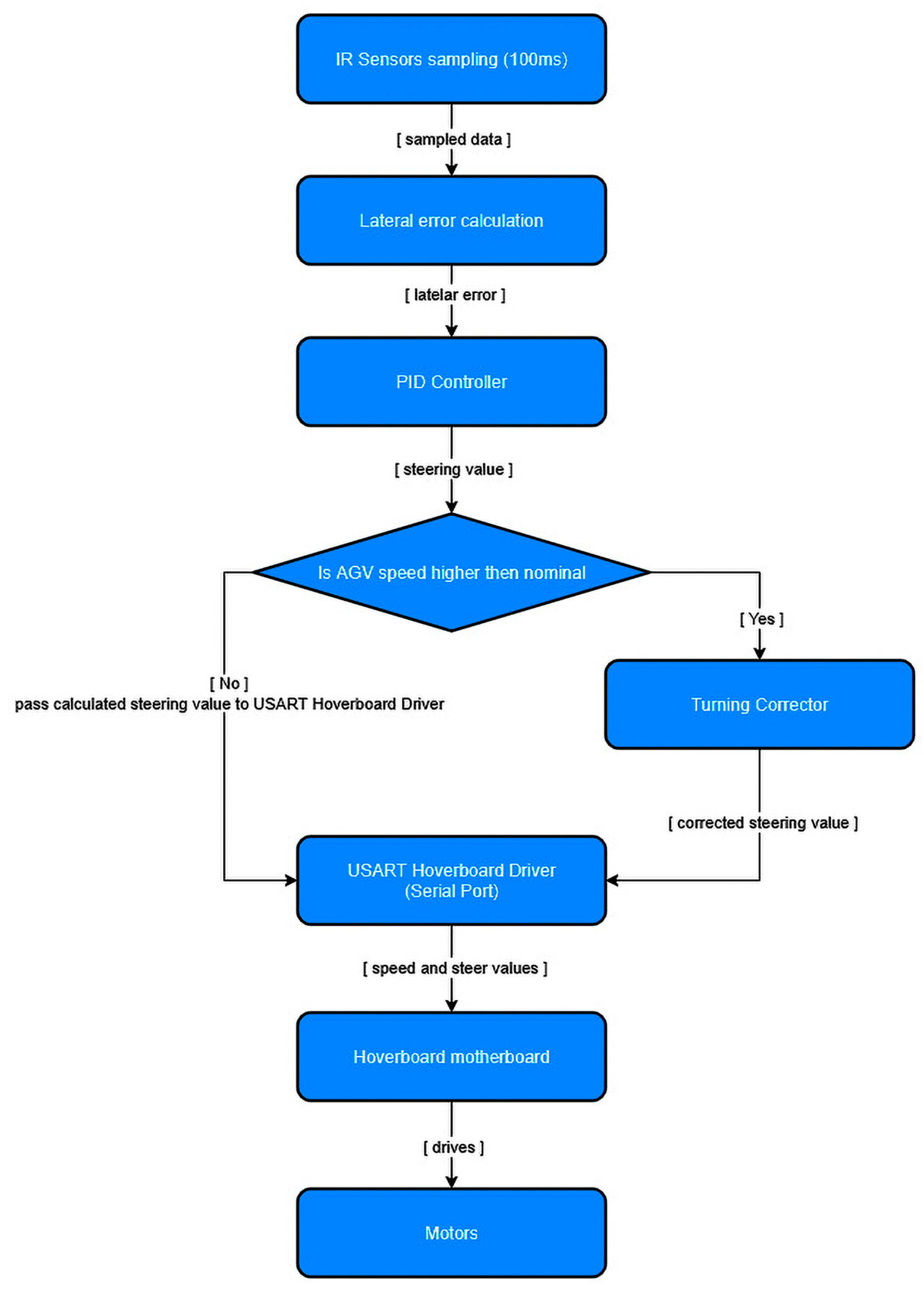
This section presents the mathematical foundations, tuning methodology, and modeling assumptions underlying the PID control [40] used to navigate the developed AGV. The AGV is a differential drive mobile platform that follows a predefined line using infrared (IR) sensors and a hoverboard-based drive system. The PID controller computes speed and steer values based on the deviation of the AGV from the desired trajectory, while a secondary correction layer (Turning Corrector) compensates for dynamic effects due to inertia at higher (non-optimal) speeds. It is important to note that speed and steer values are clamped at maximum of 250 hoverboard units, values higher than 200 units where rarely used, while nominal speed of 0.8 m/s is achieved at 115 units. Higher speeds are used in cases when there is a need to speed up production due to short deadlines or delays in production. Based on previously stated, it is evident that most of the time PID controller is the one diving the AGV while Turning Corrector intervenes if needed only in stated situations.
The AGV platform employs a differential drive configuration with two independently actuated wheels. The kinematic model of such a system can be represented using the unicycle model, which approximates the platform’s behavior under the assumption of no wheel slip and flat ground motion:
x = v cos(θ)
y = v sin(θ)
θ = ω
where x, y represent the position of the AGV in the global frame, θ is the orientation, v is the linear velocity, and ω is the angular velocity. The angular velocity ω is derived from the differential wheel speeds v r (right wheel) and v l (left wheel) using the relation:
ω = v r v l L
with L = 0.36 m being the distance between the wheels.
The control system receives feedback from a linear array of infrared sensors placed approximately 0.35 m in front of the center of mass. This placement ensures anticipation in trajectory tracking, enabling timely corrective actions.
A standard discrete-time Proportional-Integral-Derivative (PID) controller was implemented to generate control commands for the AGV based on the line position error detected by the IR sensors:
u [ k ] = K p e [ k ] + K i T s i = 0 k   e [ i ] + K d e [ k ] e [ k 1 ] T s
where T s is the sampling period, e [ k ] is the control error, and K p , K i , K d are the proportional, integral, and derivative gains respectively. The output u [ k ] represents the desired steering correction at time step k, which is mapped to differential drive values (speed and steer) and communicated over a serial interface to the hoverboard motor controller.
The Ziegler-Nichols tuning method [41] was initially used to obtain an approximate range of PID parameters based on the system’s critical gain and oscillation period. The tuning was then refined using empirical (mostly manual) testing due to the nonlinear and dynamic nature of the hoverboard-based drive and mass-related inertia of the AGV, especially at higher speeds. The goal of PID tuning was to ensure:
  • Precise line tracking within ±2.5 cm (half the tracking line width). This ensures that most of the time center IR sensors (later labeled IR#3 and IR#4) are always aligned on top the tracking line.
  • Rapid correction from a lateral offset of up to 6 cm from the ideal center of the tracking line and up to 3.5 cm to the left and right of the edge of the tracking line.
  • Correction time within 2 s at nominal speed (0.8 m/s).
  • Optimal sensitivity to sensor noise or latency (sensors sampled every 100 ms to match serial port (USART) frequency of sending control commands).
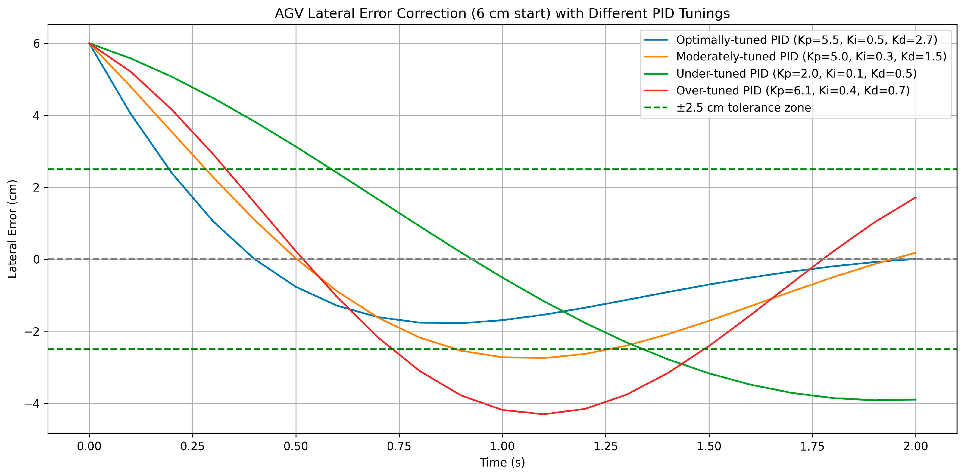
An open-loop step response was measured by applying incremental control efforts and observing the error decay. Based on this, the following groups of PID parameters were selected and labeled based on their performance:
  • Optimally-tuned PID: K p   = 5.5, K i   = 0.5, K d = 2.7 (the smoothest line tracking)
  • Moderately-tuned PID: K p   = 5.0, K i = 0.3, K d = 1.5 (provides good line tracking as well)
  • Under-tuned PID: K p = 2.0, K i = 0.1, K d = 0.5
  • Over-tuned PID: K p = 6.1, K i = 0.4, K d = 0.7
Comparison of stated groups of PID parameters is presented in Figure 4.
Optimized PID values resulted in stable line following behavior with minimal overshoot and acceptable rise time. The system responded well to moderate curvature without requiring Turning Corrector intervention.
Due to the AGV’s relatively high mass (38 kg) and centralized wheelbase (wheels located 0.3 m from both the front and rear), the system experiences inertia-related understeering during sharp turns at higher velocities. To mitigate this effect, a secondary correction mechanism referred to as Turning Corrector was introduced. While the turning corrector functionality could be integrated into the PID controller via a damping coefficient, it was intentionally implemented as a separate control layer. This design choice provides an independent mechanism that enhances stability during high-speed operation and enables additional control during AGV rotation, beyond standard line-tracking behavior.
Turning Corrector operates on raw IR input and adjusts the PID output dynamically when significant trajectory deviation is detected and vehicle speed exceeds a predefined threshold. It applies a proportional correction to the turn command to compensate for the lag in physical steering response. Under nominal conditions (normal speeds and moderate turns), Turning Corrector remains inactive, allowing the PID to maintain full control. Figure 5 sums control algorithm presented in this section.

3.2.3. AGV Navigation System

The following parts presents the sewing plant layout along with the JSON-based AGV trajectory map and the algorithm that guides the AGV from point A to point B using this map. First, a section of the sewing plant layout, including the AGV trajectory map and its elements, is introduced and examined. Next, the structure of a JSON map is detailed, followed by an explanation of the pathfinding algorithm that, besides finding an optimal route between given points A and B, creates a list of actions that the AGV needs to execute to get from point A to point B. Navigational aspects such as turning at junctions, rotation at delivery points, rotation at charging station and AGV navigation based on map elements are also discussed.
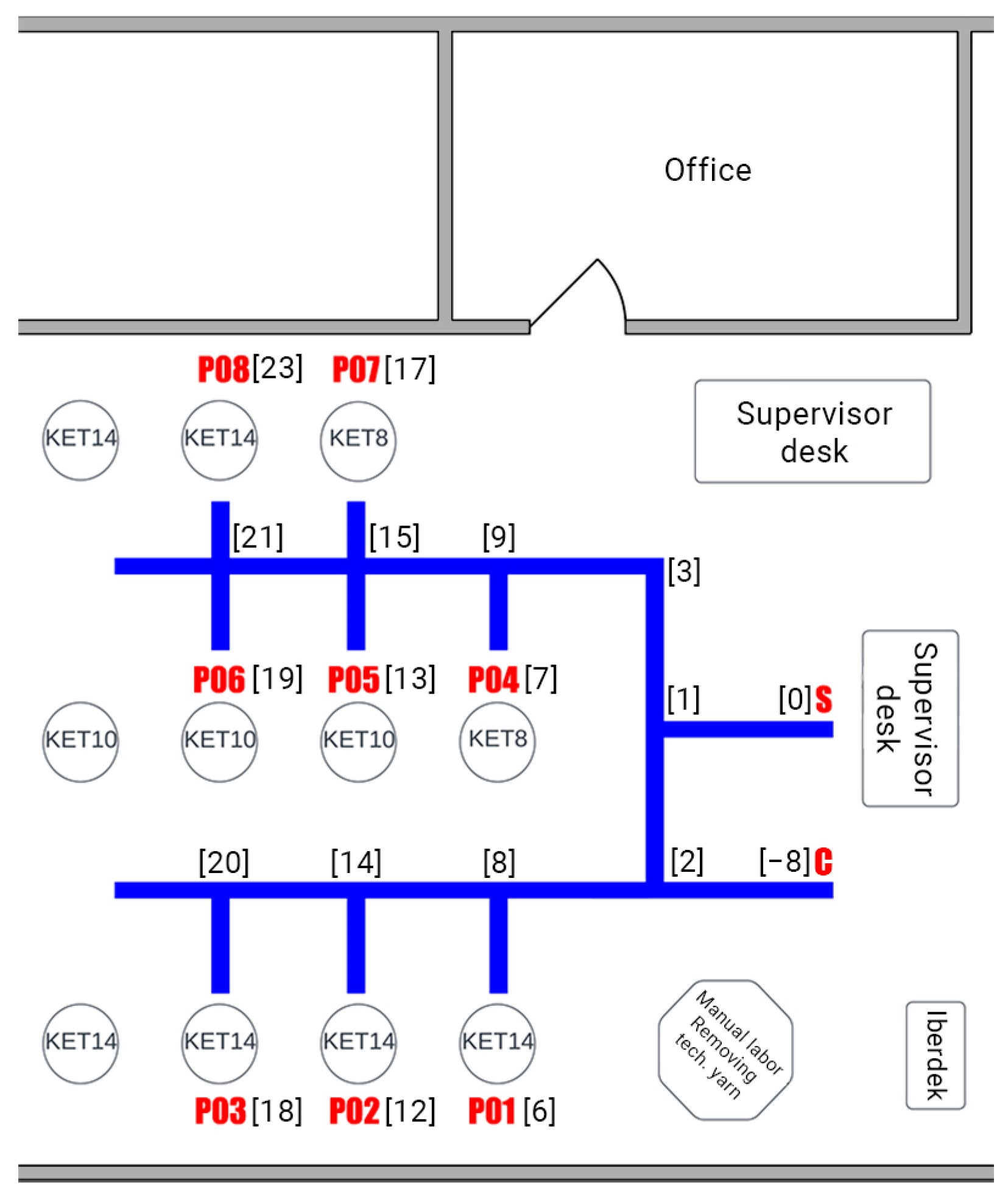
The part of sewing plant layout, overlaid with the AGV’s trajectory map (highlighted in blue), is shown in Figure 6. The trajectory itself is depicted in black on a white background; however, due to the light color of the actual factory floor, the white background was not required in practice. Delivery and pickup points are labeled as P# (where # ranges from 1 to N). The AGV’s initial position, marked with the letter S, and the charging point, marked with the letter C, are located near the supervisor’s desk (see Figure 6). The supervisor monitors the production process and issues work orders, which are used to generate corresponding AGV routes. Each route entails moving the AGV from one delivery point to another, starting from its current location. For example, as shown in Figure 6, one route might involve transporting a garment from point P08 to point P04 for finishing processes at another workstation. Another route could involve moving the item from point P04 back to the supervisor at point S for final inspection or dispatch.
The AGV trajectory map consists of junctions, delivery points, and a designated starting and charging point. From a structural standpoint, the starting point is treated as a specialized delivery point; however, it also serves to initialize the AGV’s compass orientation and provides a location for delivering finished products. The charging point is structurally identical to the starting and delivery points but provides charging functionality when the AGV backs up to the charging station.
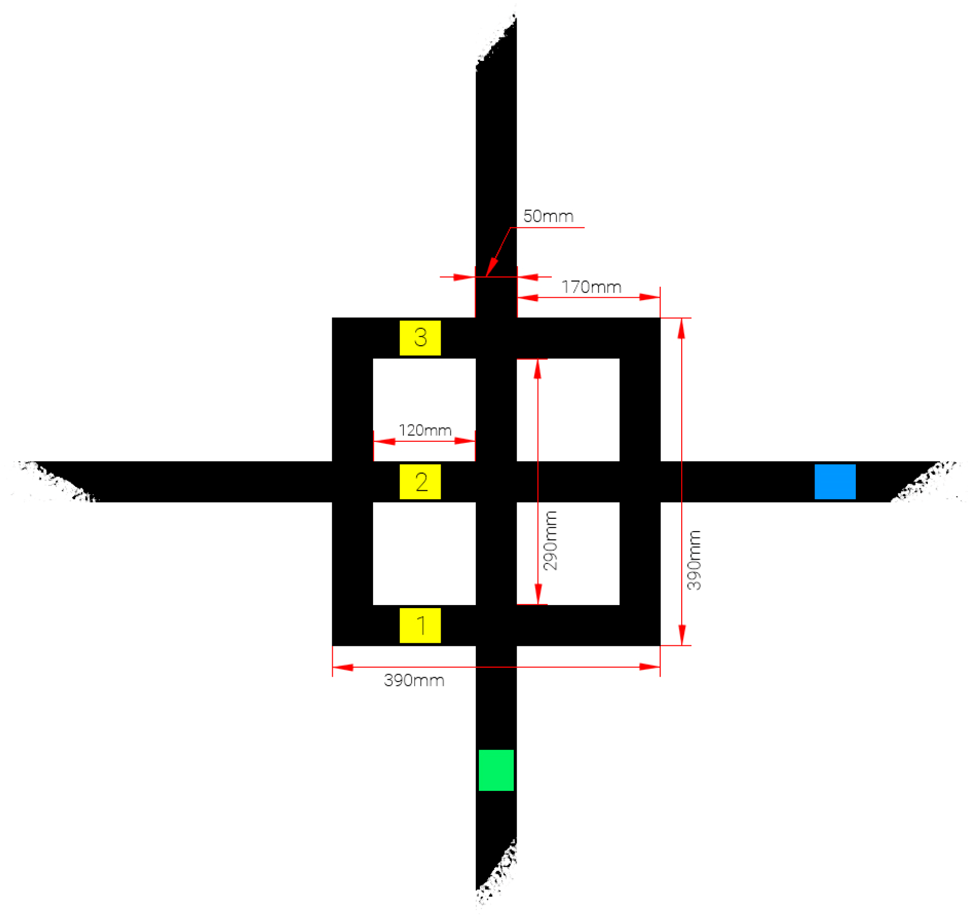
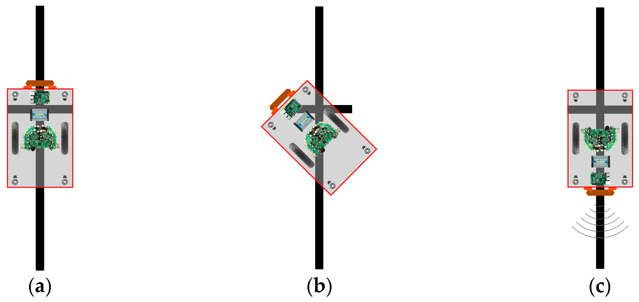
Junctions represent locations within the trajectory map where trajectory lines intersect. As the AGV approaches a junction via a trajectory line, it encounters one to three possible exit trajectories. Each exit trajectory may lead to another junction, a delivery point, or a dead end. The structural layout of a junction is illustrated in Figure 7. Trajectory lines are 50 mm in width and intersect at 90-degree angles. The intersection is enclosed by a junction square, whose sides measure 390 mm and have the same width as the trajectory lines. The center of the junction square aligns precisely with the center of the intersecting trajectory lines. When examining a junction and selecting an entry point (entry trajectory), the junction square forms three parallel lines (marked with yellow stripes and labeled 1 to 3 in Figure 7 with the trajectory line that intersects the entry trajectory (shown in blue in Figure 7). The entry trajectory itself is indicated in green. These parallel lines carry specific significance for the AGV and are detected when all six of the AGV’s infrared line-following sensors are activated. The first line (from the junction square) signals the AGV to reduce its speed in anticipation of a junction. The second line (from the intersecting trajectory line) commands the AGV to stop. The third line (again from the junction square) indicates the optimal position for the AGV to initiate a rotational movement. This junction structure is consistent, regardless of whether the junction has one, two, or three exits. If an exit does not connect to another junction or a delivery point, it is marked as a dead end. Such exits are excluded from consideration during the AGV’s pathfinding process.
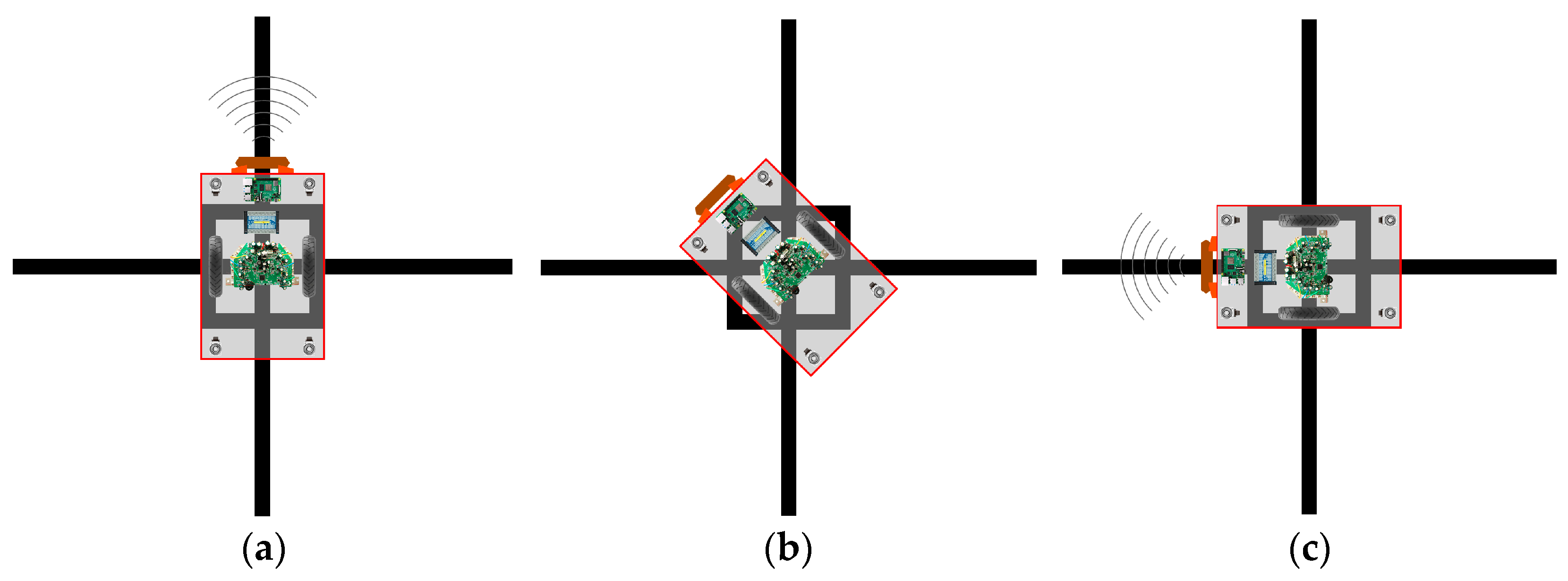
An example of an AGV performing a 90-degree left turn at a junction is illustrated in Figure 8, across subfigures (a) to (c). Figure 8a shows the AGV positioned and ready to begin the turn. At this point, the AGV’s obstacle detection system is temporarily disabled to prevent nearby workers or furniture from being incorrectly identified as obstacles, which could interfere with the turning maneuver. Figure 8b depicts the AGV in the process of making the left turn with the obstacle detection system still disabled. Finally, Figure 8c shows the AGV having completed the 90-degree left turn, with its obstacle detection system re-enabled. Throughout these maneuvers, the AGV’s compass orientation is continuously tracked, with the initial heading at the starting position aligned to the magnetic north.
Delivery points are designated locations positioned near sewing machines. Structurally, each delivery point is marked by a minimal design consisting of a single orthogonal line intersecting a trajectory line, as illustrated in Figure 9. When an AGV departs from a junction and follows a trajectory toward a delivery point, its obstacle detection system is temporarily disabled. This allows the AGV to approach the sewing machine as closely as possible without interruption.
Figure 9a illustrates the AGV arriving at the delivery point with its obstacle detection system deactivated. Upon arrival, detected by the AGV’s infrared (IR) sensors identifying the orthogonal line, the AGV comes to a stop and performs a 180-degree turn to the left. This maneuver is shown in Figure 9b, with the completed rotation illustrated in Figure 9c. In the new orientation, the AGV remains stationary until it receives a new routing assignment and a departure confirmation. This confirmation can be issued by a sewing machine operator either through an Android application or by pressing a designated button on the AGV.
Once the AGV is assigned a new route and departs from the delivery point, the obstacle detection system is reactivated to resume normal navigation, as shown in Figure 9c. The complete process of arriving at a designated delivery point and the AGV performing a 180-degree turn is illustrated in Figure 9 and its corresponding subfigures.
As previously stated, the charging point is structurally identical to the delivery point, and therefore the same behavior applies when approaching it, with one slight difference. Once the AGV has executed all maneuvers as it would when approaching a delivery point, and after completing a 180-degree turn (as shown in Figure 9c), it slowly backs up to the charger. As soon as the AGV connects to the charging port, it stops and remains in that position until charging is complete. Once charging is complete, it sends a notification to the web application and moves slightly forward to disconnect from the charger. At this point, any destination point (path) can be assigned to the AGV, allowing it to resume its tasks within the sewing plant’s production process.
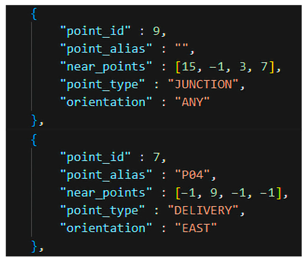
The AGV map is implemented as a JSON file, in which each junction, delivery point, and starting point is explicitly defined. The structure of a map point is illustrated in Figure 10 and is defined by five attributes:
  • point_id: A unique identifier assigned to each point. As shown in Figure 6, every point (regardless of its function) is assigned a numerical identifier displayed within square brackets. The identifier generation system for a given map is inspired by the structure of a binary search tree (BST). As illustrated, points with odd identifiers are positioned to the right, while those with even identifiers are placed to the left. Furthermore, a consistent spatial relationship can be observed: in front of any given point is another point whose identifier is greater by 6; to its left, a point with an identifier 2 less; to its right, a point with an identifier 2 greater; and behind it, a point with an identifier 6 less. This spatial logic is leveraged by the pathfinding algorithm to construct navigation paths between designated start and end points. A special case is the charging point, which has a negative identifier of −8 and is accessible through point 2.
  • point_alias: A descriptive label assigned to the point. This field is left empty for junctions; otherwise, it indicates either a starting point (denoted by “S”), charging point (denoted by “C”) or a delivery point (e.g., “P01,” “P02,” etc.).
  • near_points: An array containing four elements, each representing the unique identifier of a neighboring point that is reachable from the current point. A value of −1 indicates a dead end (e.g., an exit from a junction that does not lead to another point). The identifiers are ordered according to compass directions in the following sequence: North, East, South, and West. For instance, in the case of the point with ID 9, the array indicates that heading north leads to point 15, east to a dead end, south to point 3, and west to point 7—a delivery point. Point 7, in contrast, has −1 values for all directions except east, which leads back to point 9. Based on this configuration, it can be concluded that a delivery point functions as a junction where the entrance and exit are aligned.
  • point_type: Specifies the functional classification of the point. Valid values include junction, delivery, and start.
  • orientation: Indicates the compass direction in which the AGV is oriented at a given point. Possible values include north, east, south, west, and any, the latter being the default value assigned to junctions.
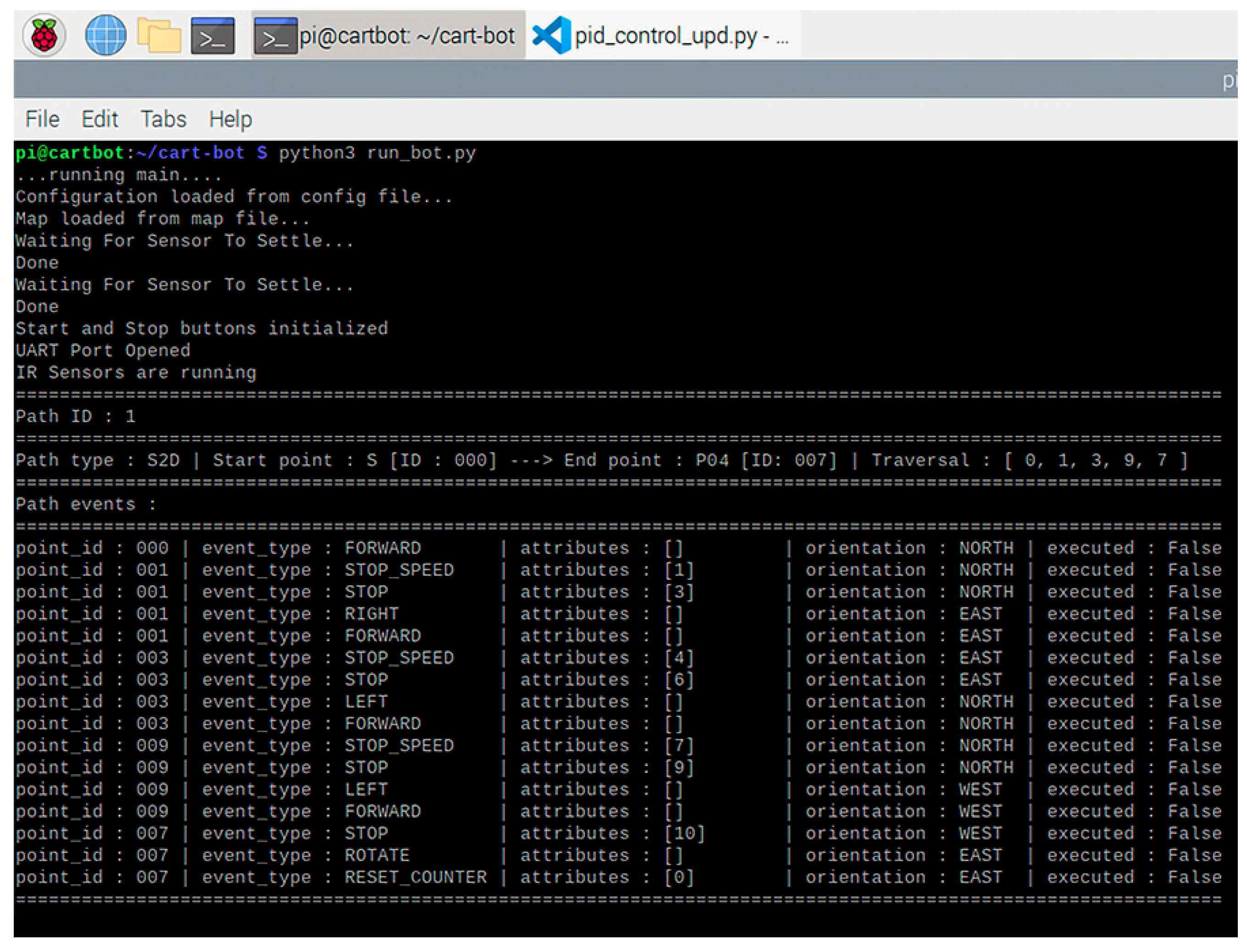
Figure 11 presents a terminal running the AGV control software, demonstrating the pathfinding algorithm for a route assigned to the AGV via a web application. During the AGV’s startup sequence, the configuration and map files are first loaded. Subsequently, the ultrasonic sensors, control buttons, UART port, and infrared (IR) sensors are initialized. Once initialization is complete, the AGV enters a standby state until a route is assigned.
When a route is assigned, the AGV determines the traversal points based on its internal map and the specified start and end locations. Along with these traversal points, the actions that the AGV must execute at specific locations, referred to as event types (as illustrated in Figure 11), are also defined. During traversal, as a method of control, the AGV keeps track of the number of orthogonal lines it crosses at junctions. As previously mentioned, each junction contains three orthogonal lines. For example, to reach point P04 from the starting point S (see Figure 6), the AGV must pass through three junctions and stop at P04, which is a delivery point containing a single orthogonal line. This results in a total of ten orthogonal lines being crossed. Once the AGV performs a rotation at a delivery point, this counter is reset.

3.2.4. Computing Platform and Connectivity

The Raspberry Pi 4 Model B was selected as the central computing platform for integrating all hardware components into a functional unit. It was chosen due to its extensive 40-pin GPIO header, high-performance CPU, sufficient RAM, and versatile interfacing capabilities. Both the LAN and wireless network interfaces proved valuable during software development (conducted using the xRDP protocol over LAN) and during testing, which was performed over a Wi-Fi network.
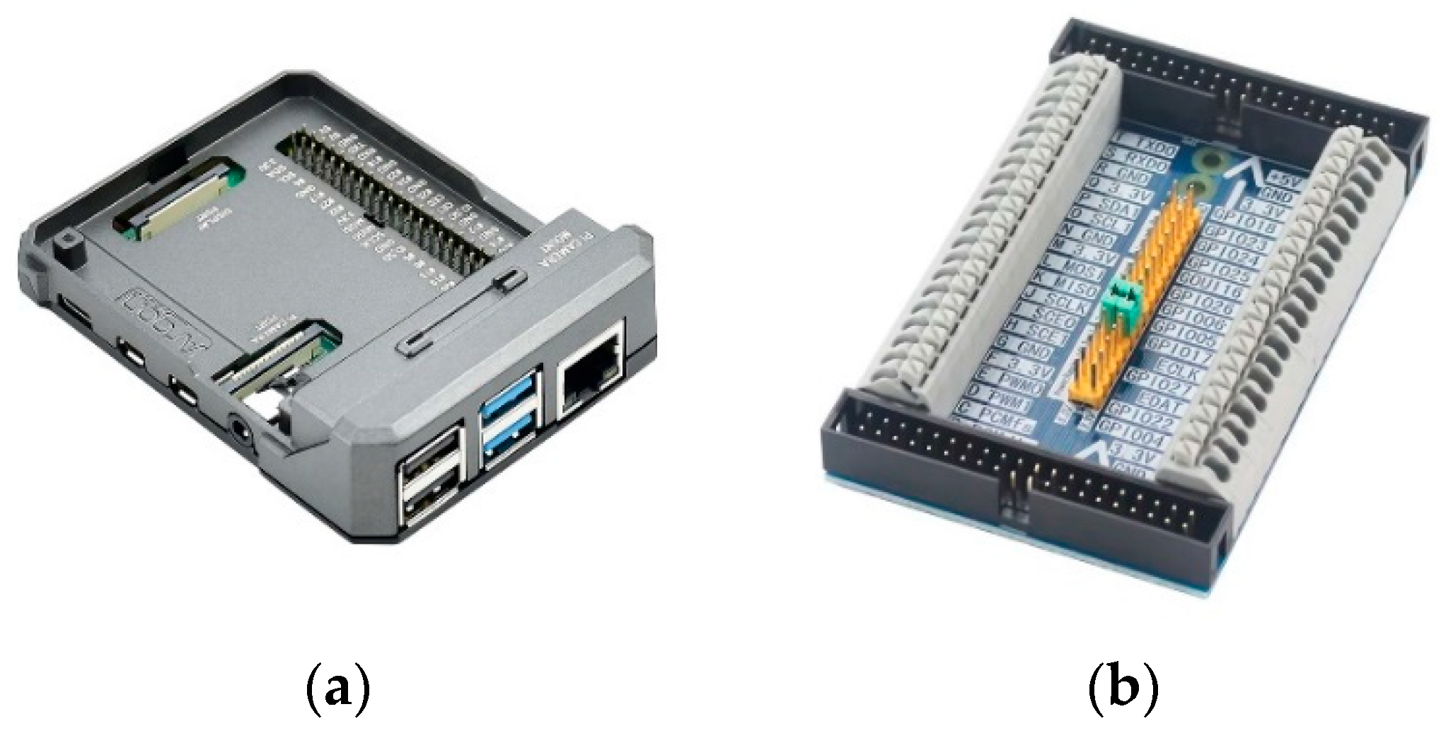
To ensure system stability, the Raspberry Pi OS (Debian version 10, Buster) was used as the operating system. The entire Raspberry Pi 4 Model B unit was housed in an Argon NEO aluminum case which provides passive cooling to prevent overheating. For improved accessibility to the GPIO header, a GPIO Pin Header Expansion Cascade Expander with quick couplers was employed. Stated elements are shown in Figure 12.

3.2.5. AGV’s Motion System

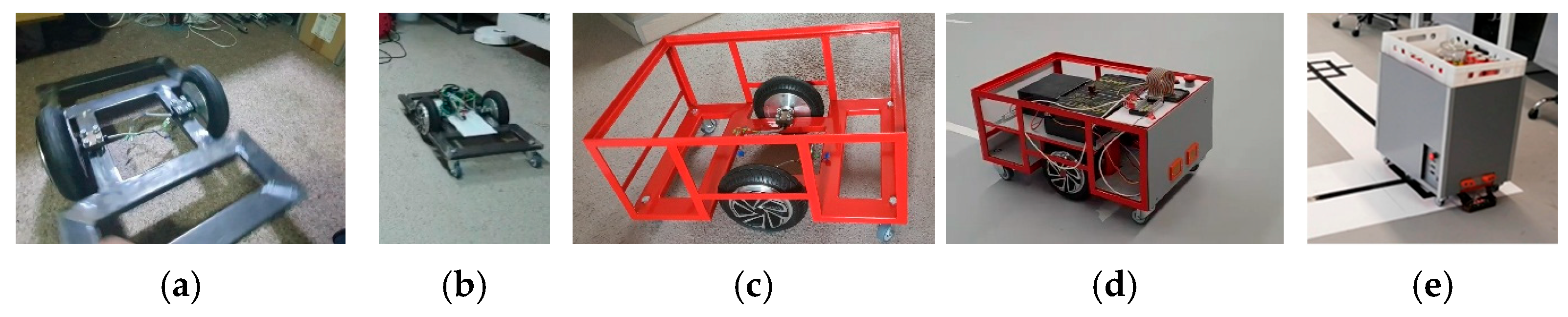
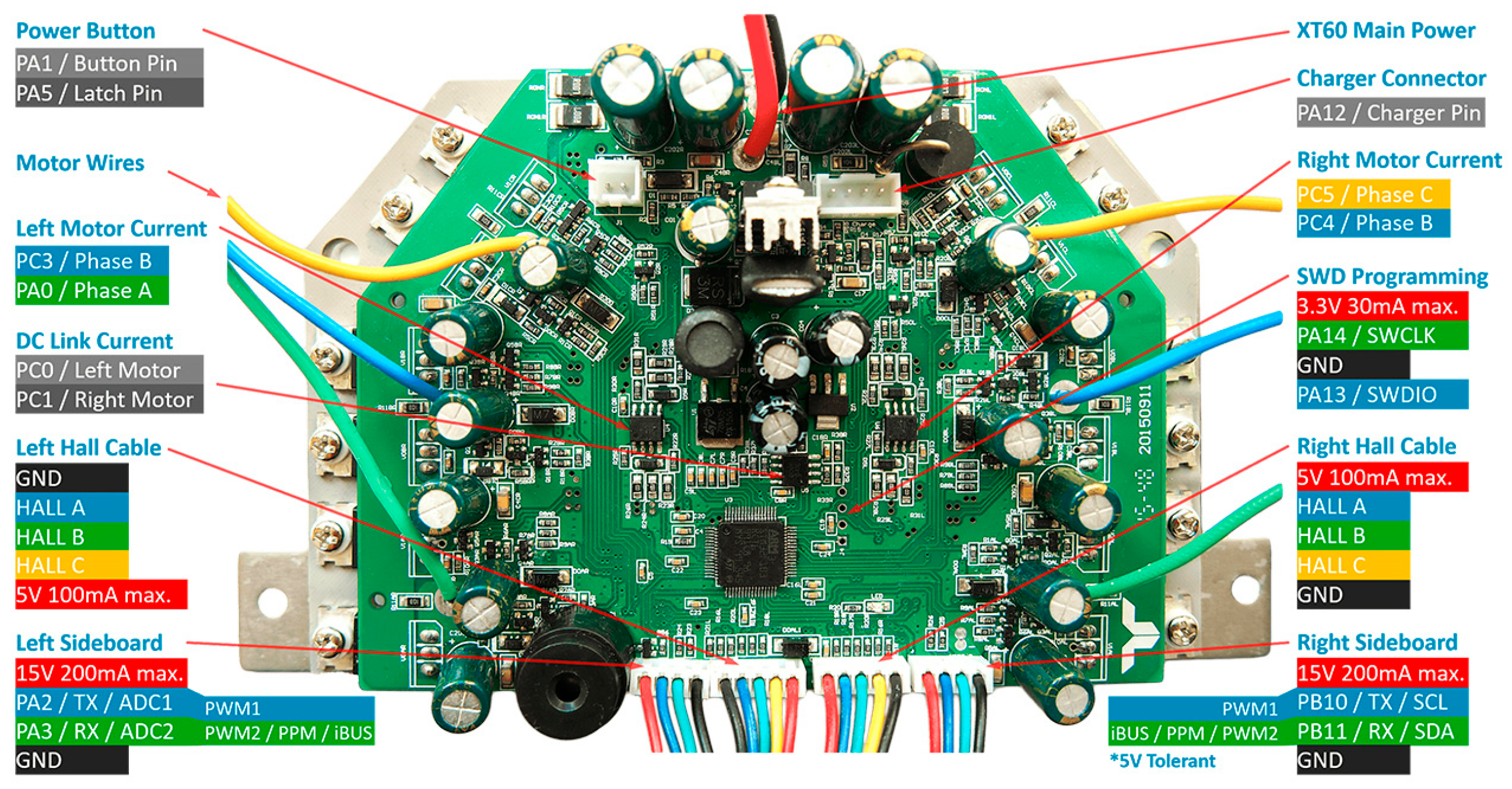
A used hoverboard was selected as the basis for the AGV due to its two high-torque motors, which provide strong load-bearing capacity, good maneuverability, and controllable speed. The motors used are brushless DC (BLDC) motors with three phases, 15 pole pairs, Wye/Star winding configuration, a resolution of 4 degrees, and integrated Hall sensors positioned 120 degrees apart. The wheels have a diameter of 8 inches and use solid tires with dimensions of 200 × 50 mm. The rated power of each motor ranges between 200 and 300 W. To integrate the system into the AGV design, the hoverboard was disassembled, and its wheels (with motors inside) and mainboard (shown in Figure 13) were mounted onto a custom-built AGV bearing frame. Having this in mind, since the only hoverboard parts that where not used are its battery, battery management system, casing and frame, we have labeled our solution “hoverboard-based” since in its base, developed AGV has a fully functional hoverboard that is perfectly balanced using small caster wheels.
To control the hoverboard (and by extension, the AGV) it was essential to understand the features and architecture of the hoverboard’s mainboard. For this purpose, the firmware modification developed by [42] was employed. The hoverboard mainboard typically features an STM32F103RCT6 microcontroller. However, some versions utilize the GD32F103RCT6 microcontroller, which is also supported by the aforementioned firmware. Both microcontrollers are based on a 32-bit ARM Cortex-M3 CPU and differ primarily in clock speed, flash memory, and SRAM capacity with the GD32F103RCT6 offering superior specifications in these areas. In terms of peripherals, both microcontrollers include 3 × 12-bit analog-to-digital converters (ADCs) and 2 × 12-bit digital-to-analog converters (DACs). For interfacing, they support 2 × I2C, 3 × SPI, CAN 2.0B, USB 2.0, SDIO, and 5 × USART/UART communication interfaces.
To upload hoverboard firmware modification given by [42], it was first necessary to unlock and erase the flash memory of the STM32F103RCT6 microcontroller using the STM32CubeProgrammer. Subsequently, the modified firmware (configured for the USART communication variant) was compiled and uploaded via the serial interface using Visual Studio Code and the PlatformIO plugin. This process enabled serial communication with the hoverboard. The next step involved establishing a UART connection between the hoverboard and the Raspberry Pi 4 Model B. Due to the high baud rate requirement of 115,200 bps for reliable communication with the hoverboard via UART, it was necessary to use the PL011 UART controller (mapped by default to/dev/serial1 or ttyAMA0), which provides better throughput and stability than the Mini UART (ttyS0, mapped to/dev/serial0). Mini UART’s clock source is tied to the VPU (VideoCore) core frequency, which fluctuates during operation and may consequently alter the UART baud rate, leading to unstable communication and potential data corruption.
By default, the Mini UART (ttyS0) is assigned to the TX and RX GPIO pins (GPIO14 and GPIO15), while PL011 (ttyAMA0) is used for the onboard Bluetooth module. To enable reliable serial communication on GPIO14 and GPIO15 using the PL011 interface, it was necessary to reassign ttyAMA0 to these pins. This was achieved by disabling the onboard Bluetooth module, which caused the UART interfaces to be remapped: ttyAMA0 was redirected to the serial GPIO pins (as/dev/serial0), while ttyS0 was reassigned to the disabled Bluetooth interface (as/dev/serial1). Although this remapping can also be achieved without disabling Bluetooth (by including a specific configuration directive in the boot configuration) it was decided to disable Bluetooth entirely, as it was not required for the application.
To interface with the hoverboard via serial communication, a custom serial controller was developed in Python version 3.11 based on [40]. The hoverboard’s USART interface is configured by default to operate at 115,200 baud, with 8 data bits, no parity, and 1 stop bit (8N1 configuration). Control is achieved by sending binary command frames that follow structure defined in [42], formatted as little-endian byte arrays, every 100 milliseconds. Hoverboard is run using a custom serial controller that has two threads: one for sending steer and speed values to a hoverboard every 100 milliseconds and one for receiving feedback from the hoverboard. Stated steer and speed values range from −1000 to 1000 indicating that 0 is a standstill value and that the higher the value the larger the intensity of an action. Negative values for steer turn the hoverboard to the left, while positive values turn him to the right. Same analogy applies to moving a hoverboard backward and forward. During the project there was never any need to use values larger than 200 units (positive or negative depending on the task at hand) even when AGV was transporting a load with maximum predicted weight.

3.2.6. AGV’s Guidance System: Line Following

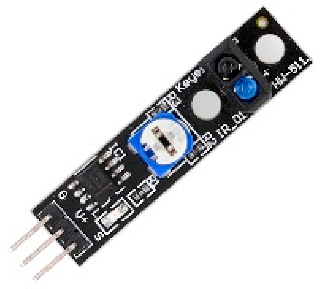
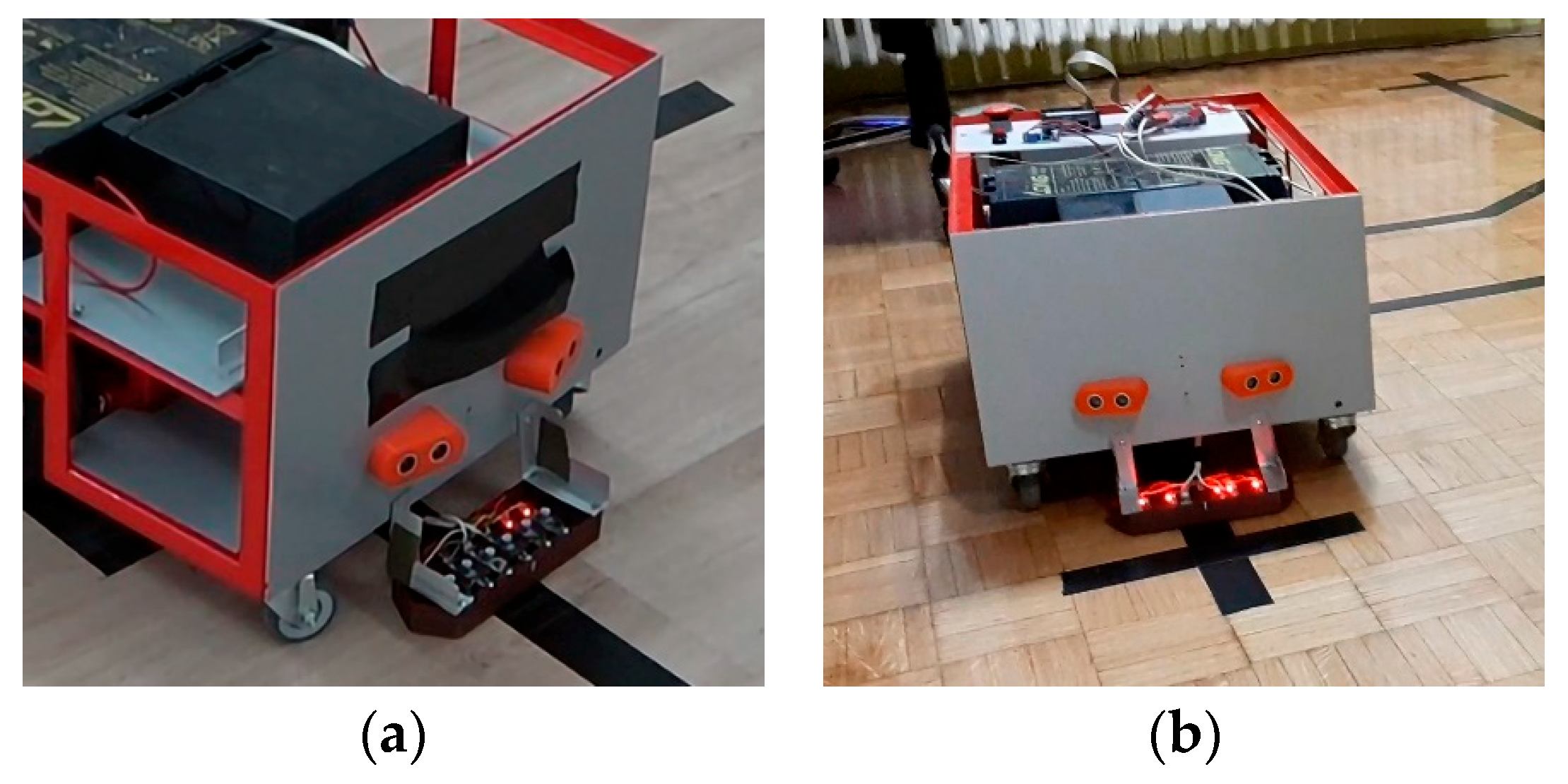
To enable line following, six TCRT5000 infrared (IR) sensors (shown in Figure 14) were mounted in a linear arrangement on a 3D-printed holder positioned at the front of the AGV (shown in Figure 15). Each sensor is labeled IR# (where # ranges from 1 to 6). For ease of calibration while mounted, each sensor was modified in a manner that the IR emitter and receiver face downward toward the tracking line, while the distance-adjustment trimpots face upward, allowing for convenient access.
The polling rate of the IR sensors is set to 100 ms. The sensor readings (lateral error calculation) are continuously transmitted to a PID (Proportional-Integral-Derivative) controller [40], which governs the AGV’s steering behavior. With this setup, the AGV is capable of following tracking lines of arbitrary curvature. However, due to the layout constraints within the sewing plant, only straight tracking lines were implemented. Where tracking lines intersect, they do so at orthogonal (90-degree) angles. The structure of these junctions and their role in navigation will be discussed in a subsequent section.
The functionality of the IR sensors varies depending on the AGV’s current action: line following using the PID controller, executing 90-degree turns (left or right), or performing a 180-degree rotation when entering or exiting a delivery point. During standard line following, the sensors are used to maintain the AGV’s alignment with a 5 cm-wide tracking line. Sensors IR3 and IR4 are positioned over the center of the line and are primarily responsible for keeping the AGV on course. Sensors IR2 and IR5 serve as early indicators of deviation; they detect when the AGV begins to drift off the line. If either IR1 or IR6 detects the tracking line, it indicates a significant deviation. In such cases, the AGV halts and performs a recovery maneuver: it steers in the opposite direction while moving forward slowly until IR2 or IR5 realigns with the tracking line.
A 90-degree rotation requires switching from tracking mode to rotation mode. When initiating a left turn from a tracking line, IR1 and IR2 are triggered sequentially, indicating they have crossed the orthogonal line. This is followed by IR3 and IR4 becoming active, signifying that the AGV is aligned with the new tracking line. For a right turn, the same sequence occurs with IR6 and IR5 activating first, followed by IR3 and IR4. Once the turn is completed and the AGV realigns with the tracking line, the system switches back to tracking mode.
During rotation, the AGV’s speed is set to zero, while the steering value is set to −160 for left turns and 160 for right turns. The rotational speed is dynamically adjusted based on sensor input: activation of IR1 or IR6 reduces speed by 50%, activation of IR2 or IR5 reduces it by 25%, and when both IR3 and IR4 are triggered, the steering value is set to zero and the AGV stops, completing the rotation. Occasionally, due to inertial effects, the AGV may overshoot slightly during rotation, causing IR3 or IR4 to move off the tracking line. To address this, a previously stated corrective module, referred to as the Turning Corrector, was implemented. Although the PID controller realigns the AGV upon resuming movement, the Turning Corrector provides immediate post-rotation alignment, ensuring precise repositioning. While not strictly necessary this feature has become a standard component of the AGV’s control architecture.
A 180-degree rotation follows the same principles and logic as a 90-degree turn, with the distinction that it occurs exclusively at delivery points. Consequently, the AGV remains on the same line before and after the turn.

3.2.7. Obstacle Avoidance

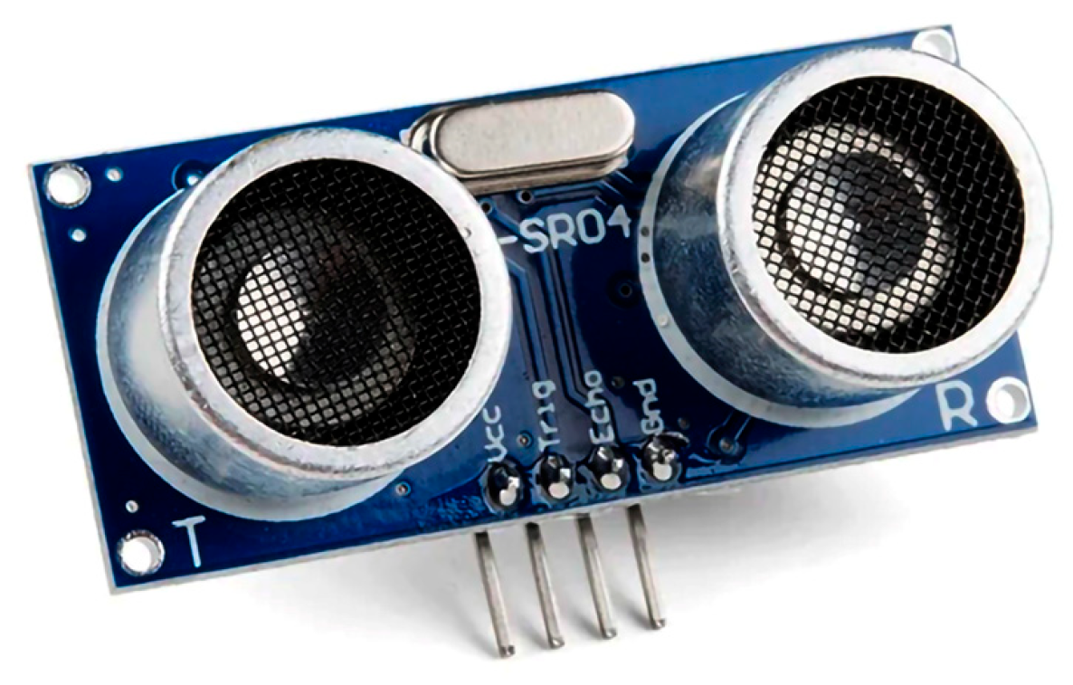
To ensure safe operation in the sewing plant environment and prevent collisions with personnel, two HC-SR04 ultrasonic sensors (shown in Figure 16) were mounted on the front of the AGV using a custom 3D-printed housing (shown in Figure 15). Given that the AGV operates exclusively in a forward-moving, line-following mode, front-facing obstacle detection was deemed sufficient.
When an obstacle is detected (e.g., a worker steps in front of the AGV), the AGV immediately halts. Once the obstacle is cleared (i.e., the path becomes unobstructed), the AGV gradually accelerates back to the speed it was traveling at prior to the interruption. The HC-SR04 sensors have a nominal field of view of approximately 50–60 degrees, with an effective detection angle of around 30 degrees. To maximize forward and peripheral detection coverage, the sensors were mounted at an outward angle of 30 degrees from the AGV’s centerline. This configuration allows for the detection of obstacles not only directly in front of the AGV but also slightly to the sides—an essential feature in dynamic environments where individuals may approach the AGV from lateral directions, similar to pedestrians crossing a path.
Given this coverage, additional sensors on the sides or rear of the AGV were deemed unnecessary. The ultrasonic sensors operate with a refresh interval of 100 milliseconds and trigger a stop command if an object is detected within a 40 cm range.

3.2.8. Bearing Frame and Supply Power

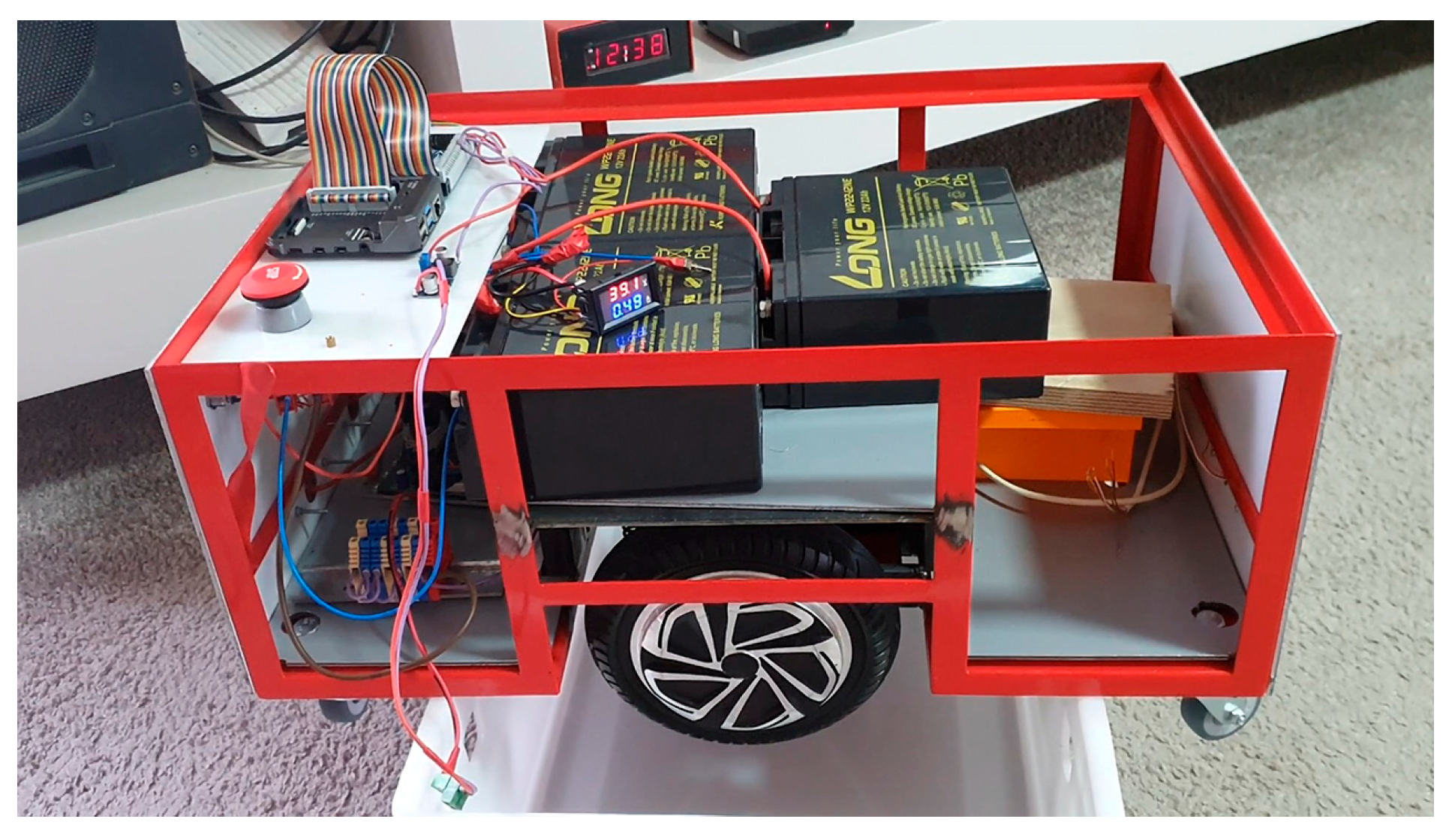
The components described in the previous sections are assembled onto a custom-designed bearing frame, which, with most of the hardware installed, is shown in Figure 17. The frame dimensions are 235 mm in height, 395 mm in width, and 590 mm in length. The hoverboard wheels are mounted on a centrally positioned load-bearing platform, supported by springs to improve shock absorption and weight distribution. Additionally, small caster wheels are installed at each corner of the frame to enhance the AGV’s stability. With the hoverboard and caster wheels included, the total height of the AGV is 310 mm. With the load-bearing box added, the overall height increases to 600 mm.
To support its intended function of transporting materials and both partial and finished products, a lightweight load-carrying frame with an attached cargo box is mounted on top of the AGV, as illustrated in Figure 1. Power is supplied by three Long WP22-12NE 12 V 22 Ah lead-acid batteries connected in series, providing a total output of 36 V that is sufficient to power the hoverboard motors. The Raspberry Pi 4 Model B and its connected sensors are powered from the same battery system using an LM2596S DC-DC step-down converter, which reduces the voltage from 36 V to the 5 V required for stable operation of the computing platform.

3.2.9. Charging System

The AGV is equipped with a dedicated charging interface integrated directly with its onboard battery pack. Recharging is accomplished via a custom-designed charging station (shown in Figure 18), which functions both as a custom-built charger and as a docking interface that is tailored to the voltage and current requirements of the AGV’s battery system. Stated charging station is also designed to regulate charging parameters such as current limit, voltage cut-off, and thermal protection to ensure battery safety, efficiency, and longevity.
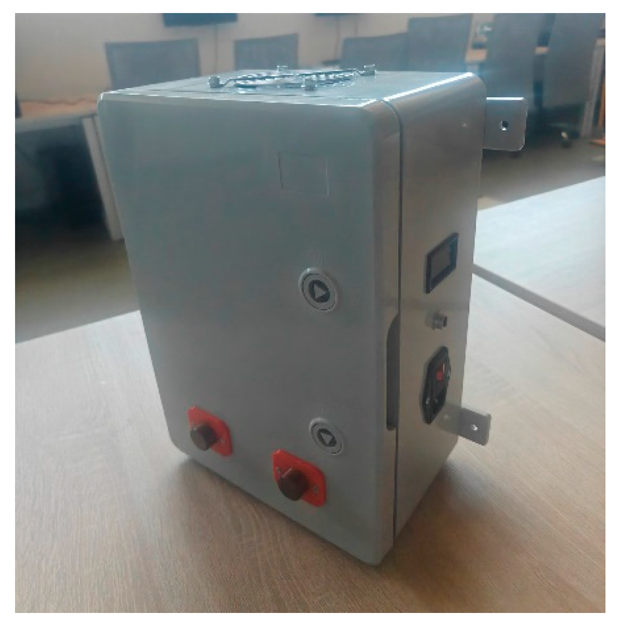
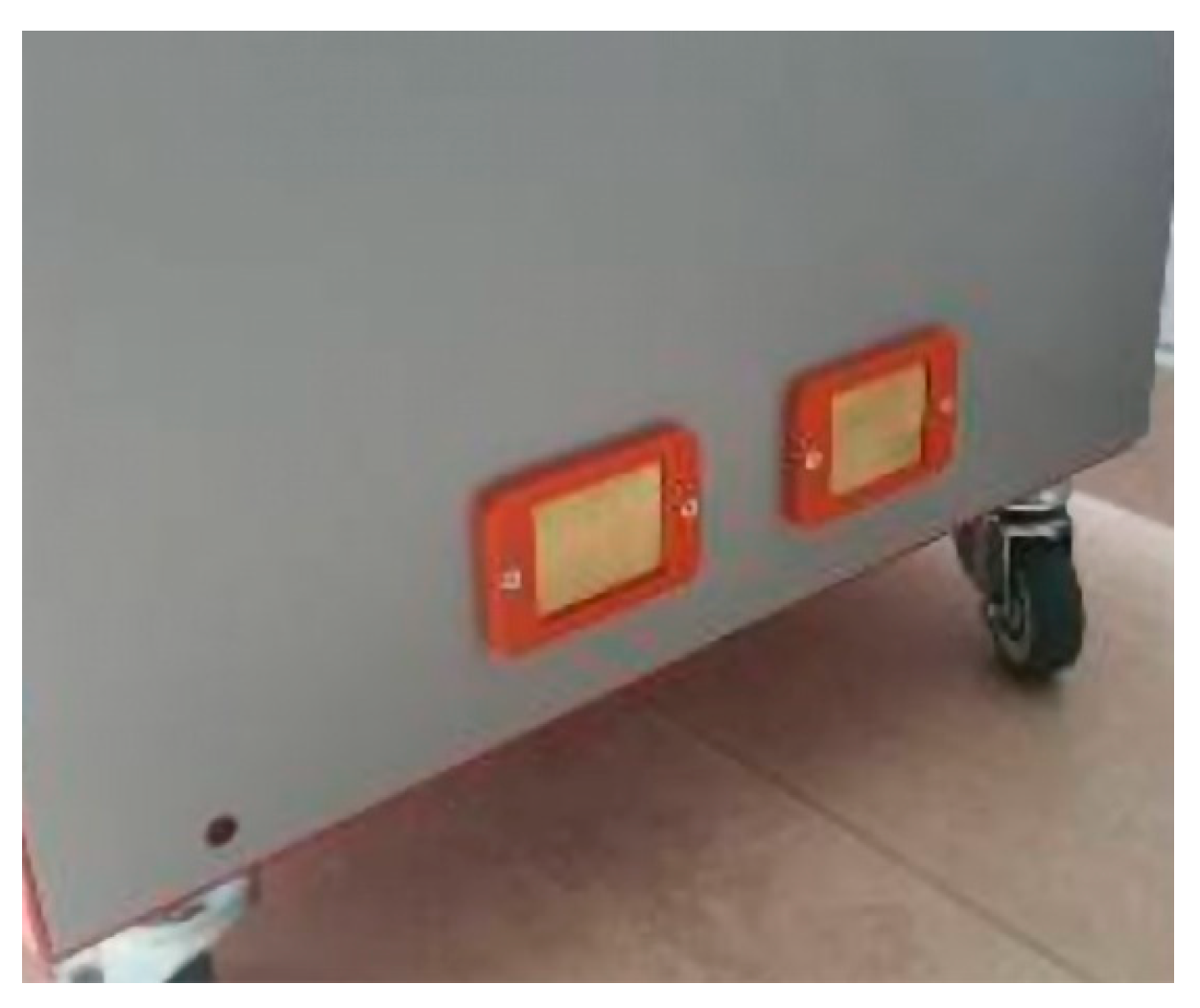
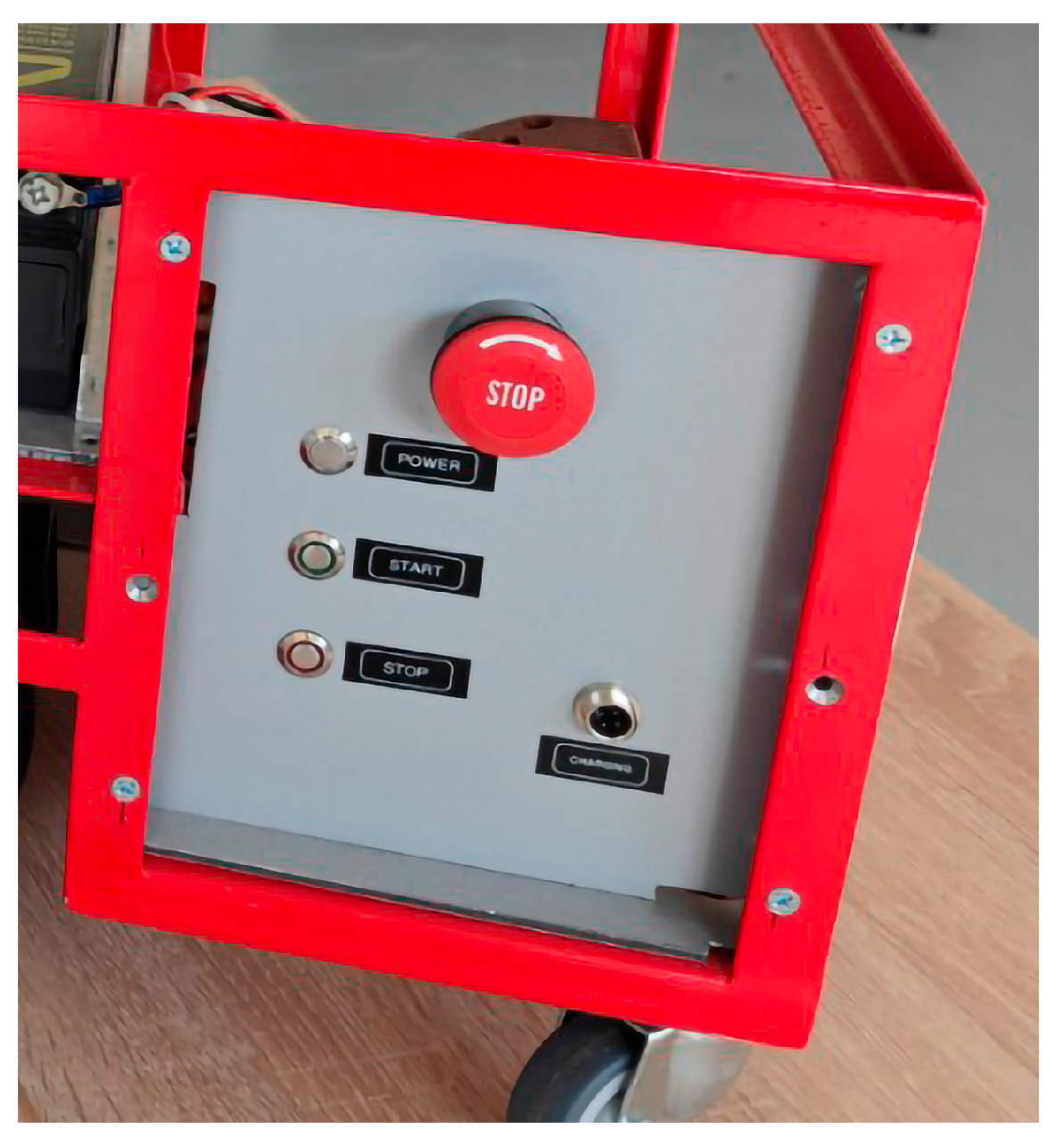
The AGV is designed to autonomously reverse into the charging station to initiate the charging process. Electrical connection between the AGV and the charging station is established through a passive contact-based mechanism, which ensures both mechanical simplicity and electrical reliability. Specifically, the rear end of the AGV is fitted with two copper contact plates (shown in Figure 19), which align and make physical contact with two corresponding copper knobs mounted on the charging station. The contact-based design eliminates the need for active connectors or human intervention, facilitating a fully automated and repeatable charging process. The system ensures precise alignment during docking, typically aided by the AGV’s IR sensors and control algorithms. Figure 20 illustrates a dedicated, custom-built charging port located adjacent to the AGV’s control panel. This port enables the charging station to function as a conventional charger.

3.2.10. Control Panel

The developed AGV is equipped with four hardware control buttons, as illustrated in Figure 20. Three of these are metallic push button switches (labeled Power, Start and Stop), while one is an emergency stop button featuring a mushroom head and turn-to-release mechanism. The function of each button is as follows:
  • Emergency Stop Button—When turned, it enables power delivery from the batteries to the AGV. When pushed, it cuts off battery power to the entire system. This button is essential for safety and must be released (i.e., turned) before any other system can be activated.
  • Power Button—When pressed, it powers on the AGV if it is not already active. Specifically, it initiates startup of the Raspberry Pi 4 Model B and the hoverboard motor controller, allowing the AGV to initialize correctly. This button is used immediately after the emergency stop is released, as part of the standard startup sequence.
  • Start Button—When pressed, the AGV begins executing its assigned path. It assumes that the AGV is already powered on and has received a path command.
  • Stop Button—When pressed, it stops the AGV from executing its current path and places the system in a waiting state, ready to receive a new assignment.
By following the prototyping procedures presented in Section 3.2, this research directly addresses the first research question: whether retrofitted, hoverboard-based equipment can serve as a viable foundation for construction AGV system in industrial environments. The successful integration of salvaged consumer electronics, combined with functional mobility, navigation, and control features, demonstrates that such an approach is not only technically feasible but also economically advantageous for SMEs. This validates the premise that low-cost, repurposed platforms can be transformed into operational AGVs without requiring major infrastructural changes, thereby opening new possibilities for affordable automation in resource-constrained manufacturing settings.

3.3. AGV Control Software

As already mentioned, the development of the hardware and software components of the AGV was carried out in parallel. The AGV software architecture comprises two primary components: the system software (discussed in detail in the previous subchapters) and a web application that serves as the interface for assigning pickup and delivery routes and acts as a manufacturing control system. The movement of the AGV is fully controlled by this application, which is designed to optimise production workflows and reduce operational costs within the sewing plant.
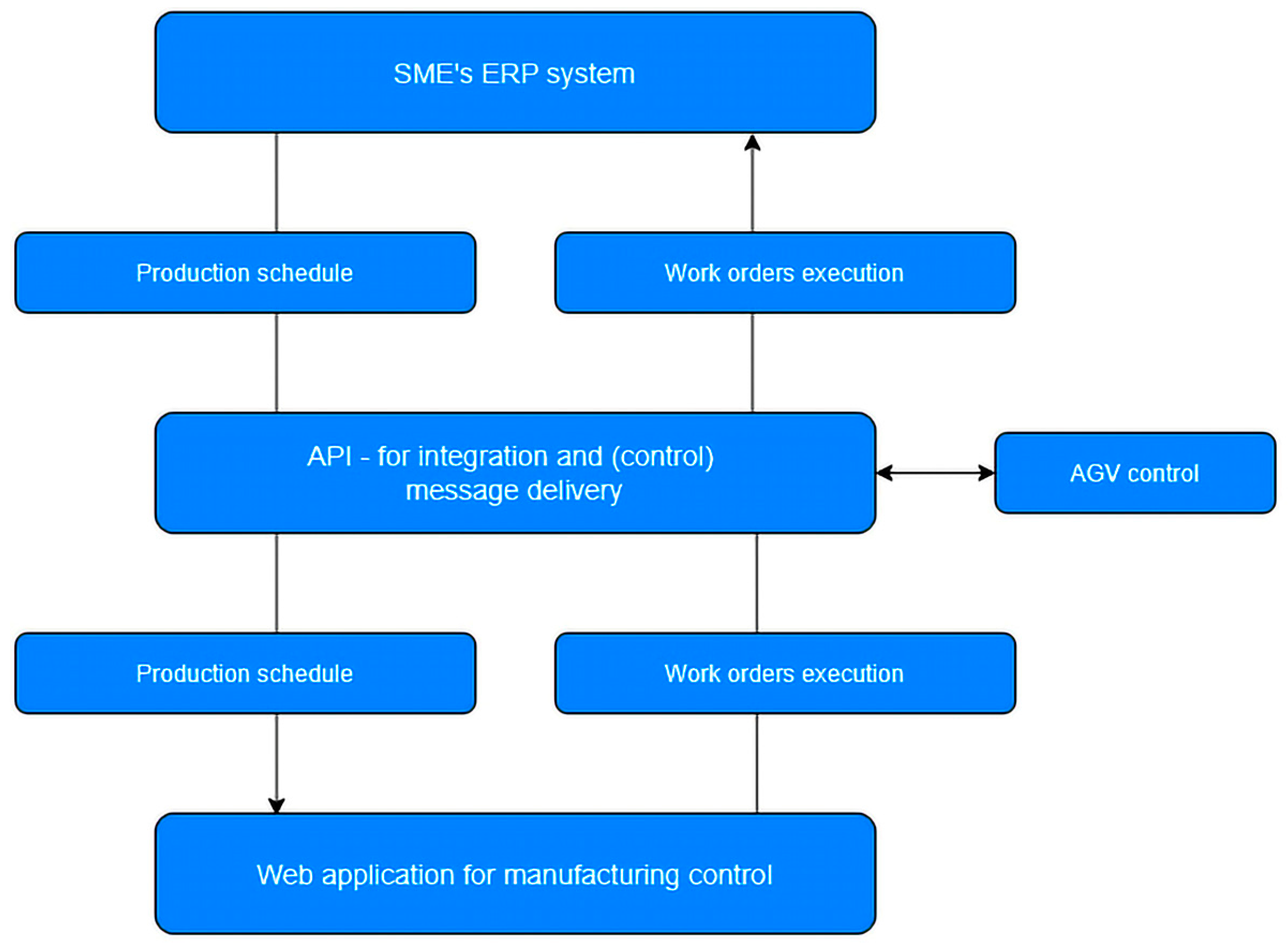
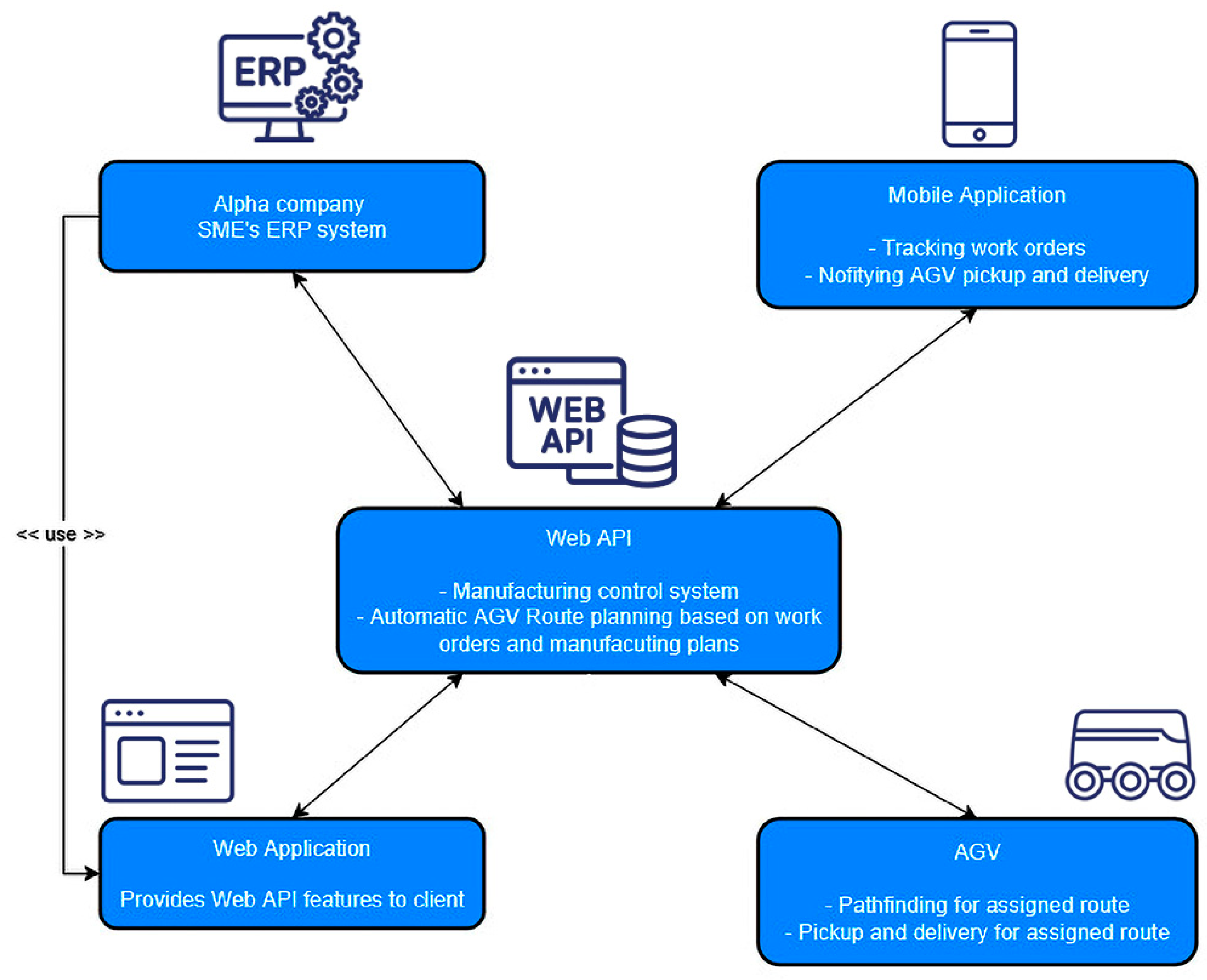
Figure 21 shows the position of the developed application and its connection to the existing ERP system, as well as to the developed AGV system, while Figure 22 shows the overall integration of all developed components and data flow structure of the entire developed solution. In this study, special emphasis is placed on the development of the AGV hardware solution, which is accompanied by the development of corresponding software. A detailed elaboration of the software aspects of the developed solution falls outside the scope of this research. Therefore, this paper focuses specifically on how the AGV and its control software are integrated into the existing information environment. It also discusses how the implementation of both the AGV and the developed software contributes to enhanced productivity, as demonstrated through established key performance indicators (KPIs).
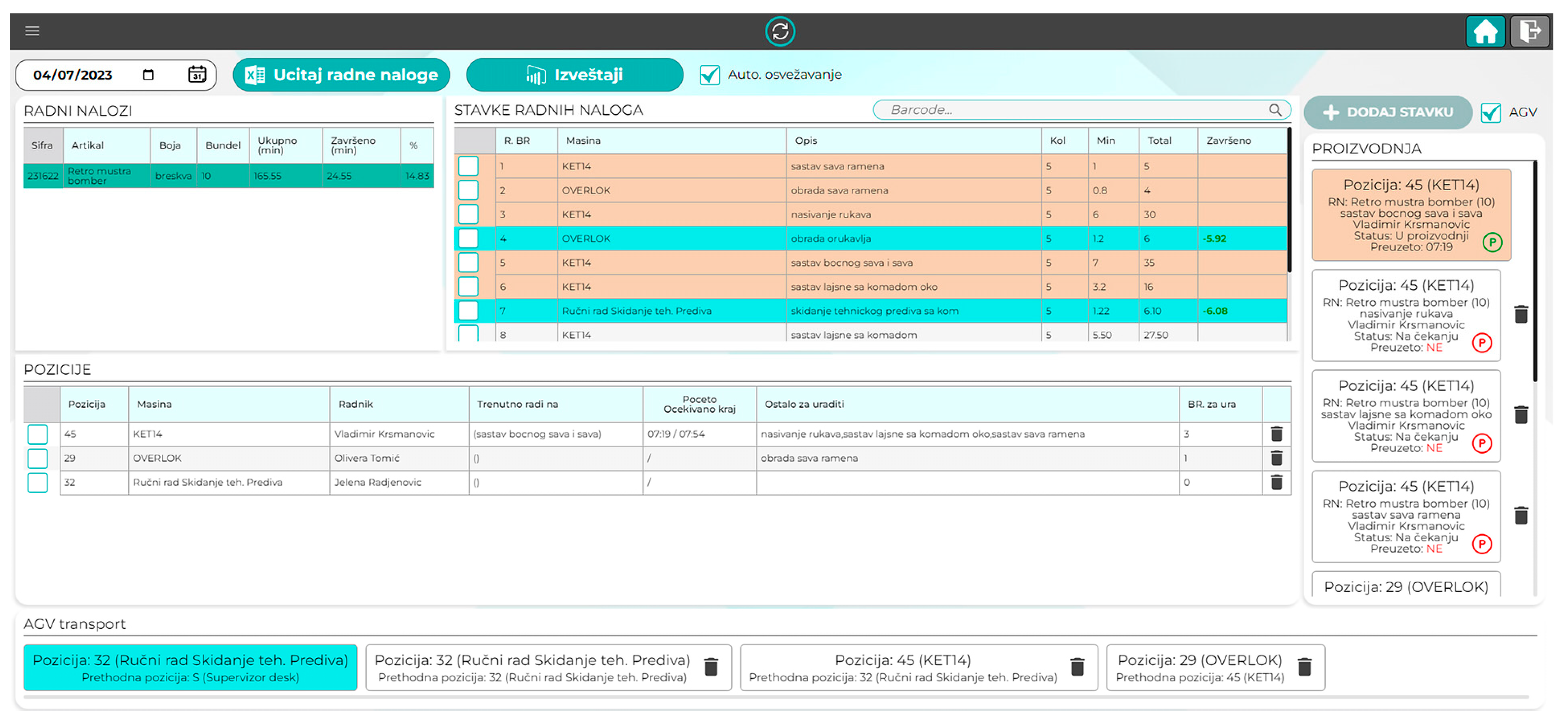
The web application helps in visualization of material flows through the production system and in creation of real-time data tracking. This cloud-based application allows Alpha to create work orders for each assembly location. Work orders are generated in the existing ERP system and imported into the web application, which then generates the production plan, including workload and sequence of operations. The production supervisor manages production sequencing through this application, with the option to fine-tune work order execution based on real-time conditions in the plant. Each workstation is equipped with a smartphone and mobile application through which operators confirm the status of work orders assigned to them. All material movement between workstations is performed automatically by the AGV according to the plan generated and controlled by the given web application.
Based on the work orders created through this application, AGV routes are generated. Each work order consists of multiple work order items, as illustrated in Figure 23. A work order item contains a set of parameters that are monitored throughout the execution of the associated task, which is typically performed on designated sewing machines. The parameters included within a work order item are: ordinal number, machine identifier, article type, color, description of the operations to be performed, item quantity, estimated execution time, actual execution time (with start and end times shown in a Gantt chart), total duration of the operation, and the deviation between the estimated and actual execution times. These data points are then used to track performance and optimize production scheduling. The value of the previously mentioned time deviation (defined as the difference between the estimated and actual operation execution times) provides critical insight into various aspects of production efficiency. Depending on whether this value is positive or negative, the following conclusions can be drawn: identification of which workers demonstrate the highest efficiency for specific operations; recognition of operations that are most complex and time-consuming, thus requiring extended execution times; detection of operations during which workers most frequently make errors, inferred from delays in all subsequent tasks; recommendations for reorganizing production workflows and machine usage to minimize idle time, thereby enhancing overall efficiency and production throughput.

4. Case Study Results and Discussion

4.1. Experimental Evaluation of the Proposed AGV’s Technical Performances

The previous chapter, which analyzed the design and implementation of a hoverboard-based line-following AGV tailored for textile manufacturing environments, has already provided an affirmative answer to the initial question of whether such a solution can be applied in an industrial setting. This paper applied an approach fully focused on optimizing textile production operations through a low-cost, custom-built AGV designed for a specific segment of the industry. By considering the unique characteristics of the sector, we optimized the AGV’s design and construction, removing unnecessary functions that off-the-shelf solutions might include but are not required in this branch or for a specific company. Importantly, the proposed AGV is easily adaptable to other textile companies and can be tailored to their specific operational needs.
Considering the novelty regarding the proposed navigation system, it can be concluded that, although the PID controller does not directly control the motors but rather the hoverboard itself, a high level of control has been achieved. It was also concluded that it would be preferable to control the hoverboard via PWM (Pulse Width Modulation), which would provide even more precise control due to its higher frequency of control signal transmission. In contrast, communication over the serial port is limited to 100 ms intervals. Pathfinding was implemented using an algorithm resembling a binary search tree (BST) traversal, with node visitation tracking, which internally provides additional information about the AGV’s position. Since the robot’s orientation is internally monitored, starting from a fixed initial position facing north, integrating an IMU sensor would be beneficial. This would provide an additional layer of confirmation for both the robot’s position and orientation, while also supplying inertial data that could further enhance stability and help maintain the robot’s trajectory.
The effectiveness of the developed line-following AGV has been evaluated across several technical KPIs: line-following accuracy, speed-stability trade-off, obstacle avoidance, recovery from line loss, and resilience to lightning variations.
When it comes to technical KPI1: Line-following accuracy, the AGV demonstrated high line-tracking accuracy under standard indoor conditions. Across 25 test runs along a complex path consisting exclusively of straight-line segments, the AGV consistently maintained its position within 1 cm to the left or right of the line center while in motion. At junctions requiring a change in direction, the AGV executed an in-place rotation around its center before proceeding along the subsequent straight segment.
Tests was conducted within a sewing plant, following the layout shown in Figure 6. This limitation was based on prior observations indicating that longer paths do not significantly influence AGV behavior, due to its constant speed and the fact that it always stops to perform directional changes. Considering the line width of 5 cm, the observed ±1 cm deviation corresponds to operation within the central 40% of the line, thereby ensuring reliable tracking performance across all trials. Table 3 shows results of mentioned 25 test runs. Five paths with different complexities were selected, and each one was run 5 times while tracking AGV deviation from tracking line and therefore result in in average deviation for selected path.
Considering the technical KPI2: Speed vs. stability trade-off, tests across three speed levels (low: 0.5 m/s, medium: 0.8 m/s and high: 1.1 m/s) revealed that line-following accuracy degrades at higher speeds. At high-speed Turning Corrector intervened periodically as the average line deviation increased to within 72% of the central line thus indicating that control stability diminishes as speed increases. At even higher speeds, ranging from 1.3 to 1.5 m/s, the Turning Corrector was activated frequently, indicating significant tracking instability. Among the tested configurations, the medium speed setting (0.8 m/s) offered the most favorable trade-off between traversal time and control accuracy.
Regarding the technical KPI3: Obstacle avoidance, the developed AGV features ultrasonic-based obstacle detection for real-time collision avoidance. During tests involving dynamic (moving) obstacles, the AGV successfully stopped at a safe distance of approximately 40 cm (with a deviation of up to—1 cm) in 23 out of 25 test runs that are presented in Table 3, resulting in a reliability rate of 92%. In the two instances where the AGV failed to meet the 40 cm threshold, it halted at approximately 34 cm, which is still within a safe and acceptable margin. Future system enhancements may include the integration of vision-based sensors to improve spatial awareness and responsiveness to complex obstacle behavior.
Considering the technical KPI4: Recovery from line loss, in the event of line loss, the AGV immediately halts and initiates a recovery procedure by applying opposite steer and speed reduced by 20%. This corrective behavior continues until the line is re-detected, at which point the PID controller and Turning Corrector resume normal operation. Given that the developed AGV is designed to follow only straight lines and execute turns exclusively as 90-degree in-place rotations, the likelihood of line loss at higher speeds remains low. Under optimal speed conditions (0.8 m/s), no instances of line loss were observed across all trial runs. If the AGV fails to reacquire the line within 5 s, it stops, transmits a recovery signal, and awaits manual repositioning, either to the nearest point on the path or to the starting position.
Finally, regarding the technical KPI5: Robustness to lighting and surface conditions, performance was consistent under controlled indoor lighting (300–500 lux). Under strong ambient light the IR sensors experienced saturation, causing occasional false line detection or erratic behavior. Applying a light shield over the sensors and adjusting thresholds in software mitigated these effects but did not fully eliminate them. Surface reflectivity also impacted performance—glossy white surfaces occasionally triggered false line readings. For optimal performance, a black tracking line should be paired with a matte with surface, or a white line with a mate dark surface.

4.2. Technological Procedure and Production Efficiency After the Introduction of AGV

The main aim of the proposed production automation at Alpha was to create a low batch size assembly system based on AGVs, which would quickly move sub-assemblies through each assembly operation. This system is supported by custom-developed software that controls material flow so that movement can be dynamically adjusted between operators and workstations without following a fixed path through the plant. In this way, production cycle time can be reduced and work-in-progress (WIP) inventory minimized, since only a small amount of work will be queued behind each operation.
The proposed AGV-based automation system replaces the current approach, in which operators take large bundles of around 50 pieces from the tailoring department to start the assembly process. Instead, the new system uses smaller bundles of 5–10 pieces, each tagged for material flow tracking and real-time information gathering. This enables dynamic production scheduling across operators and operations. The AGV delivers each small bundle to a workstation. The operator processes the bundle and, upon completion, signals the system so the AGV can transport the material to the next workstation. This organized workflow with small batch sizes also helps address quality and rework issues. If the final visual inspection reveals defects, only the small bundle is returned for correction, which causes far less disruption than reworking a bundle of 50 pieces.
With this automated assembly system, information flow will be more efficient and responsive. The supervisor will have real-time visibility and make decisions using the developed application, shifting the role from daily operational planning to process control. Additionally, by materializing the assembly flow, providing real-time WIP information at every workstation, sewing operations will become more standardized in terms of time and workload. This will help management define production targets per line more easily, without the need to handle large amounts of WIP material unnecessarily.
At the outset of the case study experiment, it was anticipated that the implementation would impact company Alpha by reducing WIP inventory, increasing manufacturing efficiency, and lowering overall operational costs. Accordingly, the following key performance indicators (KPIs) were selected to assess the effects and contributions of the proposed AGV-based automated solutions on the efficiency of the company’s manufacturing processes: (1) manufacturing lead time; (2) WIP inventory; (3) batch size; (4) production efficiency; (5) order to delivery time; and (6) waste rate. In addition to these primary KPIs, further qualitative observations and feedback were gathered to provide a comprehensive evaluation of the solution’s effectiveness and potential for wider adoption.
In the experiment one AGV was introduced to the sewing production department in order to replace manual movement of garment units between workstations. The stated KPIs were observed and analyzed within the period of one month after the AGV implementation, based on the following parameters (Table 4).
When observing the production efficiency results based on the defined KPIs, Table 5 provides a summary of the relevant data. The values represent one month of operation and refer only to the assortment of finished products currently in production for the ongoing season, rather than the company’s full product range.
These findings indicate that the proposed AGV-based solution can contribute significantly to enhancing the flexibility and efficiency of manufacturing processes in the studied textile company. Therefore, SMEs in the textile industry should consider the development and implementation of tailor-made AGV-based automation solutions, given their cost-effectiveness and positive impact on production performance.
Although several studies discuss the theoretical feasibility and potential benefits of AGVs, there is a lack of research demonstrating the practical advantages and challenges of implementing AGVs in the textile industry. Traditionally, textile factories rely on higher conveyors, which are less flexible. Overall, there has been limited experimentation with AGV applications in this sector. The textile industry often struggles with low profitability and financial liquidity issues, largely due to excessive WIP inventory. In this context, our research offers a low-cost AGV solution that provides flexibility while reducing WIP, addressing one of the industry’s most critical problems. In this way, the paper addresses the second key question regarding the impact of this solution on improving productivity and resource management in an SME textile company.

4.3. Financial Benefits of the Developed AGV in Comparison to the Commercial Alternatives

The proposed AGV deployment comprises investments of €5000 for the vehicle, €7000 for the work-order application, and €6000 for installation/implementation (total CAPEX €18,000) with OPEX €100/month. Relative to the displaced manual material-handling role (€1100/month gross), the net monthly saving is €1000 (≈€1100 − €100), implying a simple payback of 18 months (CAPEX/OPEX-adjusted saving = €18,000/€1000) and an approximate simple annual ROI of ~67% (12 × €1000/€18,000). For benchmarking, the commercial alternative quoted at €30,000 CAPEX, [4] with the same €100/month OPEX yields an identical €1000/month net saving but extends payback to 30 months and lowers the simple annual ROI to ~40% (12 × €1000/€30,000). In research terms, both options deliver equivalent operating cash flows; however, the in-house system exhibits superior capital efficiency (40% lower upfront) and faster capital recovery (−12 months), reducing exposure to demand and technology risk over the payback horizon, even without considering the other achieved benefits, such as: reduced batch size, Lead time, order to delivery time and waste rate, while increasing the production efficiency.

5. Conclusions

The development of a hoverboard-based line-following AGV for application in textile manufacturing represents a practical and cost-effective approach to factory automation. By repurposing commercially available consumer electronic (hoverboard) and integrating them with infrared and ultrasonic sensors, the system achieves robust and reliable navigation with minimal financial investment. Its ability to autonomously follow predefined floor-mounted routes, coupled with wireless communication to a centralized web application, enables seamless integration into existing production environments without the need for significant infrastructural modifications. This characteristic makes the solution particularly well-suited for SMEs seeking to enhance productivity while minimizing capital expenditure. Furthermore, the research introduces novel approaches to navigation, pathfinding, and mapping that differ slightly from conventional methods used in line-following robots. These approaches offer cross-domain applicability, extending potential benefits beyond the textile industry.
The primary strengths of the system include its low cost, modular design, and its potential to significantly improve workflow efficiency through automated intra-factory material transport. Initial deployment in a real-world sewing plant environment has validated the system’s ability to reduce manual handling requirements and enhance overall operational throughput. The presented KPI results underscore the benefits of automation and the implementation of Industry 4.0 principles within a SME in the textile sector. Accordingly, this manuscript also adopts the structure of a case study and a proof of concept, as the KPI outcomes indicate that the implemented pilot project successfully demonstrates the feasibility and effectiveness of the proposed system.
Future work will focus on expanding the system’s capabilities to support multiple AGVs operating concurrently within the same mapped environment. Planned enhancements include the implementation of inter-AGV communication for real-time coordination, dynamic route optimization, and advanced collision avoidance. These upgrades aim to further streamline manufacturing processes while increasing the scalability and adaptability of AGV-based automation in the textile industry. In addition, the next development phase will introduce a visual feedback system based on serial-addressable LEDs, intended to enhance both operational safety and diagnostic visibility.
In parallel with these advancements, future development will also focus on expanding the AGV’s software architecture to support optional compliance with the ROS 2 (Robot Operating System 2) standard. Rather than replacing the existing custom-built system, this effort will introduce a dual-mode capability, allowing the AGV to operate either in its current standalone configuration or within a ROS 2-based environment. This flexible design will enable seamless integration with ROS 2 ecosystems when needed, facilitating interoperability, modular upgrades, and access to a broad range of open-source tools, while preserving the reliability and performance of the original implementation. This approach ensures adaptability across diverse deployment scenarios without compromising the existing system’s integrity.

Author Contributions

Conceptualization, P.P., Z.I. and M.M.; methodology, P.P. and M.M.; software, Z.I. and P.P.; validation, S.B., V.T. and P.P.; formal analysis, P.P.; investigation, Z.I.; data curation, S.B. and A.M.; writing—original draft preparation, P.P. and M.M.; writing—review and editing, S.B. and A.M.; visualization, P.P. and Z.I.; supervision, Z.I. and V.T. All authors have read and agreed to the published version of the manuscript.

Funding

This research received no external funding.

Data Availability Statement

The original contributions presented in this study are included in the article. Further inquiries can be directed to the corresponding author. The name of the company (referred to as “Alpha”) that facilitated the case study described in this manuscript has been withheld to ensure confidentiality.

Acknowledgments

The realization of this paper has been supported by the AGVFlexTex project (AGV-Based Production Line for More Flexible Manufacturing in the Textile Industry) with support from the DIH–WORLD initiative. The authors also wish to acknowledge the contribution of Danube DNA project (Danube Digital Transformation Network of Active SMEs Training and Knowledge Transfer Centers), co-financed through the Interreg DRP program for the period 2024–2026.

Conflicts of Interest

The authors declare no conflicts of interest.

References

  1. Filippi, E.; Bannò, M.; Trento, S. Automation technologies and their impact on employment: A review, synthesis and future research agenda. Technol. Forecast. Soc. Change 2023, 191, 122448. [Google Scholar] [CrossRef]
  2. Fang, A.; Chen, V.; McDonald, M.A. Breaking down the impact of automation in manufacturing. MIT Sci. Policy Rev. 2023, 4, 127–136. [Google Scholar] [CrossRef]
  3. Bojic, S.; Maslaric, M.; Mircetic, D.; Nikolicic, S.; Todorovic, V. Simulation and Genetic Algorithm-based approach for multi-objective optimization of production planning: A case study in industry. Adv. Prod. Eng. Manag. 2023, 18, 250–262. [Google Scholar] [CrossRef]
  4. Kubasakova, I.; Kubanova, J.; Benco, D.; Kadlecová, D. Implementation of Automated Guided Vehicles for the Automation of Selected Processes and Elimination of Collisions between Handling Equipment and Humans in the Warehouse. Sensors 2024, 24, 1029. [Google Scholar] [CrossRef] [PubMed]
  5. Björk, A. Automated Guided Vehicles: Investment and Implementation. Bachelor’s Thesis, University of Vaasa, Vaasa, Finland, 2022. Available online: https://www.theseus.fi/bitstream/handle/10024/748499/Thesis%202022%20-%20Alexander%20Bj%C3%B6rk.pdf?sequence=2 (accessed on 21 July 2025).
  6. Saadatmand, S.; Azizi, S.; Kavousi, M.; Wunsch, D. Autonomous Control of a Line Follower Robot Using a Q-Learning Controller. In Proceedings of the 10th Annual Computer and Communication Workshop Conference (CCWC), Las Vegas, NV, USA, 6–8 January 2020; pp. 556–561. [Google Scholar] [CrossRef]
  7. Goyal, N.; Aryan, R.; Sharma, N.; Chhabra, V. Line follower cargo-bot for warehouse automation. Int. Res. J. Eng. Technol. 2021, 8, 1039–2045. [Google Scholar]
  8. Jiang, Q.; Yan, H. Leader-follower Motion Control of Two Line Following AGVs using PID Algorithm. In Proceedings of the IEEE 5th Advanced Information Management, Communicates, Electronic and Automation Control Conference (IMCEC 2022), Chongqing, China, 16–18 December 2022; Volume 5, pp. 445–449. [Google Scholar] [CrossRef]
  9. Bach, S.-H.; Yi, S.-Y. An Efficient Approach for Line-Following Automated Guided Vehicles Based on Fuzzy Inference Mechanism. J. Robot. Control. 2022, 3, 395–401. [Google Scholar] [CrossRef]
  10. Aji, B.; Sutikno, S. Fuzzy Logic Algorithm of Sugeno Method for Controlling Line Follower Mobile Robot. ILKOM J. Ilm. 2023, 15, 283–289. [Google Scholar] [CrossRef]
  11. Nugraha, M.B.; Ardianto, P.R.; Darlis, D. Design and implementation of RFID line-follower robot system with color detection capability using fuzzy logic. In Proceedings of the 2015 International Conference on Control, Electronics, Renewable Energy and Communications (ICCEREC), Bandung, Indonesia, 27–29 August 2015; pp. 75–78. [Google Scholar] [CrossRef]
  12. Gomes, M.V.; Bássora, L.A.; Morandin, O.; Vivaldini, K.C.T. PID control applied on a line-follower AGV using a RGB camera. In Proceedings of the 19th IEEE International Conference on Intelligent Transportation Systems (ITSC), Rio de Janeiro, Brazil, 1–4 November 2016; pp. 194–198. [Google Scholar] [CrossRef]
  13. Anand, M.; Kalaiselvi, P.; Kumar, S.A.; Nithyavathy, N. Design and Development of Automated Guided Vehicle with Line Follower Concept using IR. In Proceedings of the 5th International Conference on Electronics, Communication and Computing Technologies (ICECCT), Erode, India, 22–24 February 2023; pp. 1–11. [Google Scholar] [CrossRef]
  14. Vitekar, P.; Harne, V.; Kulkarni, H. Design and control of line follower automated guided vehicle. J. Eng. Sci. 2020, 11, 406–411. [Google Scholar]
  15. Antony, M.; Parameswaran, M.; Mathew, N.; Sajithkumar, V.S.; Joseph, J.; Jacob, C.M. Design and implementation of Automatic Guided Vehicle for hospital application. In Proceedings of the 5th IEEE International Conference on Communication and Electronic Systems (ICCES), Coimbatore, India, 10–12 June 2020. [Google Scholar] [CrossRef]
  16. Martins, O.O.; Adekunle, A.A.; Adejuyigbe, S.B.; Arowolo, M.O.; Adeyemi, H.O. Prototype line following Automatic Guided Vehicle (AGV) for unit load dispatch in an office environment. FUDMA J. Sci. 2019, 3, 415–423. [Google Scholar]
  17. Karthikeyan, A.; Kumar, A.R.; Afsal, A.A.; Emmanuel, C.J.; Jijithprasanth, S. Design of AGV robot for patrolling and monitoring. J. Emerg. Technol. Innov. Res. 2022, 9, 420–428. [Google Scholar]
  18. Chowdhurya, N.H.; Khushib, D.; Rashid, M.M. Algorithm for line follower robots to follow critical paths with minimum number of sensors. Int. J. Comput. 2017, 24, 13–22. [Google Scholar]
  19. Pakdaman, M.; Sanaatiyan, M.M.; Ghahroudi, M.R. A line follower robot from design to implementation: Technical issues and problems. In Proceedings of the 2nd International Conference on Computer and Automation Engineering (ICCAE), Singapore, 26–28 February 2010; pp. 5–9. [Google Scholar] [CrossRef]
  20. Oswal, S.; Saravanakumar, D. Line following robots on factory floors: Significance and simulation study using CoppeliaSim. IOP Conf. Ser. Mater. Sci. Eng. 2021, 1012, 1–11. [Google Scholar] [CrossRef]
  21. Iqbal, M.; Omar, R. Automatic Guided Vehicle (AGV) Design Using an IoT-based RFID for Location Determination. In Proceedings of the 2020 International Conference on Applied Science and Technology (iCAST), Padang, Indonesia, 24 October 2020; pp. 489–494. [Google Scholar] [CrossRef]
  22. Pungle, R.; Andhare, A.; Pungle, D. Experimental results on position and path control of an automated guided vehicle using fixed camera at ceiling and color markers. IEAS Int. J. Robot. Autom. 2024, 13, 391–400. [Google Scholar] [CrossRef]
  23. Borate, S.M.; Jadhav, P.Y.; Navale, S.R.; Sarade, S.A. Designing a Smart Obstacle-Avoiding AGV with Mobile Controller for Efficient Line Following Navigation. Int. J. Electr. Electron. Comput. Syst. 2024, 13, 1–7. [Google Scholar]
  24. Borate, S.M.; Jadhav, P.Y.; Navale, S.R.; Sarade, S.A. Obstacle avoiding AGV with mobile controller line follower robot. Int. Res. J. Mod. Eng. Technol. 2025, 7, 2884–2888. [Google Scholar]
  25. Li, J.J.; Xu, B.W.; Yang, Y.S.; Wu, H.F. A guided ant colony optimization algorithm for conflict-free routing scheduling of AGVs considering waiting time. IEAS Int. J. Robot. Autom. 2017, 6, 69–79. [Google Scholar] [CrossRef]
  26. Van, T.N.; Van, T.P.; Duc, C.H.; Xuan, B.D. Design and fabrication AGVs for industrial product transportation with high load capacity. In Proceedings of the 12th International Conference on Control, Automation and Information Sciences (ICCAIS), Hanoi, Vietnam, 27–29 November 2023; pp. 739–744. [Google Scholar] [CrossRef]
  27. Lázár, K. Industrial robots in the textile and clothing industry. Int. J. Ind. Manuf. Syst. Eng. 2024, 9, 1–9. [Google Scholar] [CrossRef]
  28. Das, S.K. Design and methodology of line follower Automated Guided Vehicle—A review. Int. J. Sci. Technol. Eng. 2016, 2, 9–13. [Google Scholar]
  29. Das, S.K.; Pasan, M.K. Design and methodology of automated guided vehicle—A review. IOSR J. Mech. Civ. Eng. 2016, 3, 29–35. [Google Scholar] [CrossRef]
  30. Ellithy, K.; Salah, M.; Fahim, I.S.; Shalaby, R. AGV and Industry 4.0 in warehouse: A comprehensive analysis of existing literature and an innovative framework for flexible automation. Int. J. Adv. Manuf. Technol. 2024, 134, 15–38. [Google Scholar] [CrossRef]
  31. Zhang, H.; Xu, L.; Liang, J.; Sun, X. Research on Guide Line Identification and Lateral Motion Control of AGV in Complex Environments. Machines 2022, 10, 121. [Google Scholar] [CrossRef]
  32. Jang, J.-Y.; Yoon, S.-J.; Lin, C.-H. Automated Guided Vehicle (AGV) Driving System Using Vision Sensor and Color Code. Electronics 2023, 12, 1415. [Google Scholar] [CrossRef]
  33. de Oliveira, D.P.; dos Reis, W.P.N.; Junior, O.M. A Qualitative Analysis of a USB Camera for AGV Control. Sensors 2019, 19, 4111. [Google Scholar] [CrossRef] [PubMed]
  34. Lee, J.; Hyun, C.-H.; Park, M. A Vision-Based Automated Guided Vehicle System with Marker Recognition for Indoor Use. Sensors 2013, 13, 10052–10073. [Google Scholar] [CrossRef]
  35. Cheong, H.-W.; Lee, H. Requirements of AGV (Automated Guided Vehicle) for SMEs (Small and Medium-sized Enterprises). Proc. Comput. Sci. 2018, 139, 91–94. [Google Scholar] [CrossRef]
  36. Kumbhar, S.G.; Thombare, R.B.; Salunkhe, A.B. Automated Guided Vehicles for Small Manufacturing Enterprises: A Review. SAE Int. J. Mater. Manuf. 2018, 11, 253–258. [Google Scholar] [CrossRef]
  37. Sakib, M.S.; Iqbal, A.; Sami, S.K.; Hoque, H.A.; Shafil, M.A.S.; Ahmed, I.; Ali, D.M.; Rashid, D.M.R.; Shimo, S.S.; Muntasir, A.; et al. Development of Low-cost Automated Guided Vehicle (AGV) to Step towards Industry 4.0. In Proceedings of the 5th International Conference on Industrial & Mechanical Engineering and Operations Management, Dhaka, Bangladesh, 26–28 December 2022; pp. 510–520. [Google Scholar] [CrossRef]
  38. Gorlach, I.; Prinsloo, J. Development of a low-cost automatic guided vehicle (AGV). Adv. Robot. Autom. 2018, 7, 71. [Google Scholar] [CrossRef]
  39. Maslarić, M.; Bojić, S.; Todorović, V.; Mirčetić, D.; Nikoličić, S. AGV-based production line for more intelligent and flexible manufacturing in the textile industry. In New Technologies, Development and Application VII; NT 2024. Lecture Notes in Networks and Systems; Springer: Cham, Switzerland, 2024; pp. 463–473. [Google Scholar] [CrossRef]
  40. Wang, L. PID Control System Design and Automatic Tunning Using MATLAB/Simulink; Wiley-IEEE Press: Hoboken, NJ, USA, 2020. [Google Scholar] [CrossRef]
  41. Mintsa, H.A.; Eny, G.E.; Senouveau, N.; Nzué, R.M.A. Optimal Tuning PID Controller Gains from Ziegler-Nichols Approach for an Electrohydraulic Servo System. J. Eng. Res. Rep. 2023, 25, 158–166. [Google Scholar] [CrossRef]
  42. Feru, E. Hoverboard-Firmware-Hack-FOC. GitHub. 2019. Available online: https://github.com/EFeru/hoverboard-firmware-hack-FOC (accessed on 9 May 2025).
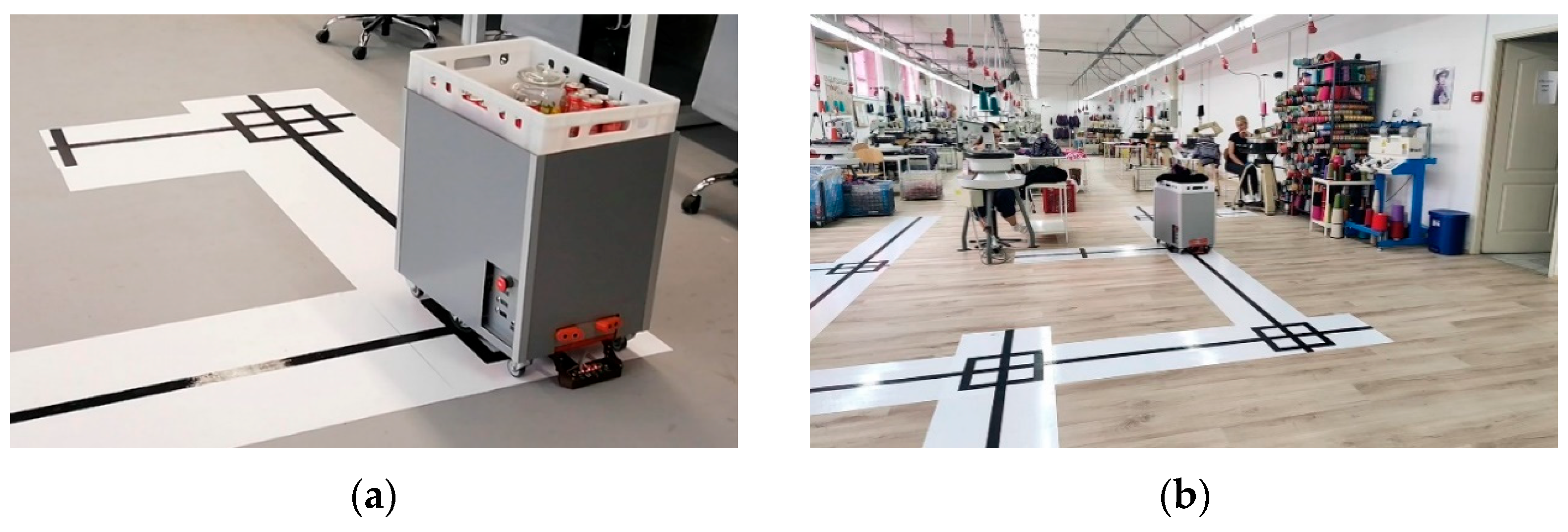
Figure 1. Developed AGV in: (a) Laboratory environment, (b) Alpha company sewing plant.
Automation 06 00072 g001
Figure 2. Layout of the sewing department in the Alpha company.
Automation 06 00072 g002
Figure 3. AGV development steps: (a) mounted BLDC motors/wheels to AGV base; (b) mounted hoverboard motherboard for preliminary testing; (c) bearing frame; (d) prototype version; (e) deployment-ready version with enclosed housing and load bearing case.
Automation 06 00072 g003
Figure 4. AGV Lateral Error Correction with Different PID Tunings.
Automation 06 00072 g004
Figure 5. AGV Control algorithm.
Automation 06 00072 g005
Figure 6. Alpha sewing plant layout with AGV trajectory map.
Automation 06 00072 g006
Figure 7. Junction structure.
Automation 06 00072 g007
Figure 8. AGV turning left: (a) ready to begin, (b) turn in process, (c) completed turn.
Automation 06 00072 g008
Figure 9. AGV making a 180 degree turn: (a) ready to begin, (b) turn in process, (c) completed turn.
Automation 06 00072 g009
Figure 10. Structure of a map point.
Automation 06 00072 g010
Figure 11. AGV startup and pathfinding for a given route.
Automation 06 00072 g011
Figure 12. (a) Argon NEO Aluminum Case and (b) GPIO Expander with Quick Couplers.
Automation 06 00072 g012
Figure 13. Hoverboard motherboard.
Automation 06 00072 g013
Figure 14. TCRT5000 infra-red sensor.
Automation 06 00072 g014
Figure 15. Sensors: (a) ultrasonic, and (b) infra-red.
Automation 06 00072 g015
Figure 16. HC-SR04 Ultrasonic sensor.
Automation 06 00072 g016
Figure 17. AGV’s bearing frame (development phase).
Automation 06 00072 g017
Figure 18. Charging station.
Automation 06 00072 g018
Figure 19. Rear end of the AGV with two copper contact plates.
Automation 06 00072 g019
Figure 20. AGV Control panel and charging port.
Automation 06 00072 g020
Figure 21. Position of developed web application within information system framework.
Automation 06 00072 g021
Figure 22. Integration of all developed components and data flow structure of the entire solution.
Automation 06 00072 g022
Figure 23. Alpha company web application—main form.
Automation 06 00072 g023
Table 1. AGV basic specification.
SpecificationValue/Description
TypePlatform (light load) AGV
Load capacityUp to 25 kg
Guidance systemLine following system with mapped points
Driving, steering system2 independent BLDC motors.
Traveling directionForward, backward, left and right turns around its center.
FramePlasticized metal frame
BrakeElectronic engine braking
Maximum rated speed8 km/h (2 m/s)
Nominal operating speed0.5–0.8 m/s
Minimum turning radius0.65 m
Sopping accuracy10 mm
Vehicle dimensions600 mm × 400 mm × 600 mm
(Height × Width × Length)
Cargo transfer height600 mm
Vehicle weightUp to 38 kg
Warning and safety devices
(bumper, lights, obstacle sensors)
Ultrasonic obstacle detection sensors and
sound signaling when reversing.
Working environment
(temperature, surface)
Working temperature range: +10 °C to +40 °C.
Flat, uniformly colored surface.
Battery capacity (cycle)22 Ah
792 Wh
Voltage (electrical system)36 V
Charging methodAutomatic (returns to charging station) or manual (via appropriate cable connection).
Sensors and camerasInfrared Line Tracking Sensor, Ultra Sonic Sensor
AGV interfaceRaspberry PI 4 Model B (GPIO + REST API + Wi-Fi)
Operating switches and
emergency stop
Power key, Forward (start) key, stop key and emergency stop key
Table 2. AGV cost summary.
ComponentQuantityCost Per Unit
(EUR)
Hoverboard178
Raspberry PI 4 Model B152
Argon NEO Aluminum Case113
GPIO Expander with Quick Coupler113
TCRT5000 infrared (IR) sensors62.6
HC-SR04 ultrasonic sensors23.4
Long 12 V 22 Ah battery352
Bearing frame, switches/buttons,
DC-DC convertors, wires
1259
Enclosed housing 143
Load bearing case18.6
Custom built charger169
Total cost714
Table 3. AGV test runs and its performance.
PathAvg. Deviation (cm)Number of RunsNumber of SegmentsNumber of Points
S → P04 → P08 → P01 → S0.675205
S → P01 → P06 → P04 → P01 → S0.545266
S → P08 → P03 → S0.815224
S → P02 → P03 → P01 → P04 → S0.685226
S → P05 → P07 → P02 → S0.735205
Table 4. Parameters used for the assessment of defined KPIs.
ParametersProduction System with Manual Material HandlingProduction System with AGV Handling
Batch size50 pieces/batch20 pieces/batch
Number of workers6463
Average walking distances per worker/shift14 to 19 km/worker/shift0 km/worker/shift
Average throughput/output rate1000 pieces/shift1280 pieces/shift
Average lead time per batch49.5 h21 h
Table 5. KPIs improvements.
KPIHow It Is Impacted by
Material Flow Automation
Achieved
Results
Batch sizeSmaller batches enabled fewer required workers, resulting in lower WIP inventory, higher flexibility, and shorter lead time2.5 times reduced
Manufacturing lead timeReduced through smaller batch sizes and decreased idle/wait time between operations2.36 times reduced per batch
WIP inventoryLower buffer accumulation, fewer defects, and increased flexibilityReduced 50%
Production efficiencyIncreased average output rate per shift Improved by 28%
Order to delivery timeReduced in relation to shorter manufacturing lead timeReduced 20%
Waste rateFewer mishandling incidents, misroutes, and product damageReduced 4%
Disclaimer/Publisher’s Note: The statements, opinions and data contained in all publications are solely those of the individual author(s) and contributor(s) and not of MDPI and/or the editor(s). MDPI and/or the editor(s) disclaim responsibility for any injury to people or property resulting from any ideas, methods, instructions or products referred to in the content.