


Abstract
Industrial robots offer flexibility and cost advantages in machining applications but suffer from limited structural stiffness and dynamic instability, leading to significant positional errors. This study presents a simulation-driven framework for automated toolpath compensation in robotic machining, integrating computer-aided design, manufacturing, and engineering environments. Finite Element Analysis is employed to predict stress, deformation, and reaction forces during machining. These predictions guide dynamic adjustments to key process parameters, such as feed rate and spindle speed, to optimize performance and accuracy. An automated optimization procedure streamlines this process, enhancing toolpath efficiency and safety. The framework is validated through a case study involving the machining of an aluminum support bracket using a KUKA KR3 robot. Simulation results demonstrate significant improvements in path accuracy, shorter machining time and enhanced surface quality. The enhanced toolpath achieves a 10–15% reduction in non-cutting movements, a 5–10% improvement in surface finish and a 15–25% decrease in machining time compared to the initial configuration. This approach eliminates the need for hardware modifications or real-time sensors, providing a flexible and modular solution for achieving high precision outcomes in robotic machining. The work presents an automated methodology for compensating multi-source errors, bridging the gap between virtual analysis and physical execution.
1. Introduction
The increasing deployment of industrial robots in machining tasks has introduced new opportunities for flexible and cost-effective manufacturing. However, their structural compliance and dynamic instability pose significant challenges to achieving the precision required in high-tolerance applications. In contrast, Computer Numerical Control (CNC) machines are automated systems that precisely control machining operations using programmed instructions. Unlike these rigid machines, robotic arms exhibit posture-dependent stiffness and are more susceptible to deflections, thermal drift, and vibrations during cutting operations [1,2,3].
While various compensation strategies have been proposed to address these limitations, each comes with trade-offs. Model-based approaches, such as stiffness and thermal drift modeling, offer predictive capabilities but lack adaptability to dynamic machining conditions. Sensor-based methods provide real-time responsiveness [4], yet they require expensive hardware and complex calibration. Hybrid systems, including digital twins and machine learning, show promise but are computationally intensive and not widely adopted in industrial settings. In contrast, the framework proposed in this study introduces a fully automated, simulation-driven compensation strategy that operates offline, integrates seamlessly with CAD/CAM/CAE workflows, and requires no additional sensors. This modular approach enables posture-aware toolpath optimization and dynamic refinement of process parameters, offering a flexible and cost-effective solution for achieving CNC-level precision in robotic machining.
While industrial robots offer significant advantages in terms of flexibility and cost, their adoption in high-precision machining remains limited due to inherent structural compliance and dynamic instability. To address these challenges, researchers have explored various simulation-driven and data-informed strategies aimed at improving robotic machining accuracy. For instance, Souflas et al. [4] developed a digital model of a machining robot using multi-body simulation and component mode synthesis to optimize feed-rate scheduling and workpiece placement, demonstrating notable improvements in process accuracy. Liao et al. [5] introduced a constant-load toolpath planning method that combines stiffness-aware posture optimization with dynamic A* algorithms to maintain machining stability. Python-based automation has also emerged as a key enabler for integrating Computer-Aided Design (CAD), Computer-Aided Manufacturing (CAM), and Computer-Aided Engineering (CAE) workflows, streamlining data exchange and enabling real-time toolpath adjustments [6]. Furthermore, Kang et al. presented an AI-augmented digital twin framework for robotic machining of CFRP materials, integrating real-time monitoring and predictive analytics to enhance machining reliability [7].
Studies have shown that vibrations, regenerative chatter, and pose-sensitive deflections are major contributors to geometric deviations and surface quality issues in robotic milling [8]. Compared to CNC machines, which benefit from rigid architectures and optimized toolpath control, robots require advanced compensation strategies to overcome their mechanical limitations [9]. Recent research has focused on dynamic modeling, stiffness optimization, and trajectory planning to mitigate these effects and bring robotic machining closer to CNC-level performance [10]. These developments underscore the need for integrated simulation and automation frameworks that can predict and correct machining errors before execution.
This study addresses these limitations by proposing a simulation-driven framework for toolpath compensation, guided by Finite Element Analysis (FEA). The framework integrates CAD, CAM, and CAE environments with automated processes to predict machining errors and apply corrective adjustments to the machine parameters. FEA simulations are used to quantify stress, deformation, and reaction forces, which inform dynamic modifications to feed rates and spindle speeds. G-code is used as the programming language to control automated machine tools. An automated procedure, developed using Python, manages the data exchange between simulation and manufacturing stages, ensuring a smooth workflow. The resulting enhanced toolpaths are validated in a robotic simulation environment, demonstrating improved accuracy and efficiency. By bridging the gap between virtual analysis and physical execution, this approach offers a scalable solution for enhancing robotic machining precision without relying on hardware retrofits or real-time sensors.
The following key contributions summarize the novel aspects of this work:
- A holistic compensation strategy that concurrently addresses structural, thermal, and vibrational inaccuracies in robotic machining.
- A fully automated data flow between CAD, CAE, and CAM platforms using Python scripting, eliminating manual data transfer and improving workflow efficiency.
- A posture-aware toolpath optimization method that dynamically adjusts feed rates and spindle speeds based on FEA-derived insights.
- A modular architecture that can be adapted to various robotic systems and machining scenarios.
- Validation of the proposed methodology through a realistic case study involving the machining of an aluminum support bracket with a KUKA KR3 robot, demonstrating CNC-level precision without hardware retrofits or real-time sensors.
The paper is organized as follows: Section 2 reviews the fundamental sources of error in robotic machining and evaluates existing compensation techniques. Section 3 presents the proposed simulation-driven framework, detailing the integration of CAD, CAM, and CAE environments with Python automation. Section 4 presents a case study involving the machining of an aluminum support bracket using a KUKA KR3 robot. Section 5 discusses the results obtained from FEA and robotic simulation, highlighting improvements in machining accuracy and efficiency. Finally, Section 6 provides a broader discussion of the findings, and Section 7 concludes the paper with key insights and future research directions.
2. Related Work
2.1. Error Sources in Robotic Machining
Robotic machining combines flexibility and cost-effectiveness, offering transformative potential for manufacturing, yet its precision is hampered by multiple error sources arising from the robot’s mechanical structure, environmental factors, and dynamic cutting processes. These inaccuracies pose significant barriers to meeting the tight tolerances demanded by high-precision industries. A comprehensive understanding of these error sources is critical to devising strategies that can elevate robotic machining to its full potential.
Structural deflection is a major challenge. Unlike rigid CNC machines, industrial robots, whether serial or parallel kinematic systems like hexapods, have lower stiffness due to their open-chain or flexible designs. During milling, cutting forces cause joints and links to flex, resulting in tooltip deviations. The extent of deflection varies with the robot’s posture, with extended configurations exhibiting reduced stiffness compared to compact ones [11]. This low stiffness leads to significant dimensional inaccuracies in high material removal rate (MRR) operations, failing to meet tolerances such as ±0.1 mm required for aerospace components [11].
Thermal expansion further undermines accuracy. Prolonged machining generates heat in the robot’s drives and bearings, causing components like gearboxes to expand. Over extended milling sessions, this thermal drift can shift the tooltip position by up to 0.15 mm, particularly due to uneven heating across joints [12]. The study emphasizes that thermal errors, driven by motor and friction heat, are significant in continuous operations, complicating precision in long-run tasks [13], as presented in Figure 1.
Figure 1.
Scheme of the indirect compensation method of machine tool thermal errors [13].
Vibrations add another layer of complexity. High-speed machining excites resonant frequencies in the robot’s structure, producing chatter that degrades surface quality. The Xing et al. [14] study shows that in a hexapod machining cell, dynamic errors driven by spindle speed, feed rate, and depth of cut, cause surface roughness to increase, with deviations linked to cutting parameter variations. For example, higher spindle speeds amplify vibrations, leading to chatter marks that impair surface finish, particularly in lightweight or less rigid systems [11,14]. Tool geometry and cutting conditions exacerbate these effects. To complement structural simulations, material-level vibration modeling using FEA, such as in graphene-reinforced composites [15], can enhance understanding of dynamic behavior in robotic machining. Additionally, advanced multiscale modeling techniques, such as those applied to CNT-enhanced composites [16] offer further insights into vibration phenomena at the material scale.
Mechanical imperfections, such as backlash, compound the issue. Small gaps in gear teeth cause positional shifts during directional changes, affecting tasks like milling and drilling. Ji and Wang [11] identifies backlash as a key error source, alongside compliance. Calibration errors also contribute, where inaccuracies in link lengths or joint offsets propagate into larger tooltip deviations across the workspace. Misalignment of the Tool Center Point (TCP) can distort toolpaths, critical for precision operations [11].
Dynamic cutting forces introduce further unpredictability. Variations in cutting conditions, such as interrupted cuts at corners, generate force spikes that increase deflections, while tool wear alters forces over time, complicating error prediction. Xing et al. [14] highlight that in hexapod machining, dynamic errors are closely tied to cutting parameters, with feed rate and depth of cut influencing tooltip deviations and surface quality. These error sources are interconnected: thermal expansion reduces joint stiffness, amplifying deflections under load, while vibrations intensify backlash effects, creating a complex error network.
For industries like aerospace and medical devices, where tolerances are as tight as ±0.05 mm, these errors are prohibitive, potentially leading to high scrap rates. Structural deflection, thermal expansion, and vibrations dominate inaccuracies, with backlash and calibration errors adding non-linear challenges. Addressing these requires a holistic approach, integrating multi-physics simulations, sensor-based monitoring, and optimized cutting parameters to capture the interplay of error sources.
Only through such comprehensive strategies can robotic machining overcome its limitations and deliver the precision needed to transform manufacturing.
2.2. Existing Error Compensation Techniques
To address the diverse and complex sources of error in robotic machining, a wide range of compensation strategies have been developed by researchers and industry practitioners. These techniques can be broadly classified into model-based, sensor-based, hybrid approaches, CAM-based optimization methods, and post-processing of G-code. Each approach offers unique advantages and limitations, and their effectiveness often depends on the machining scenario and the level of integration with CAD/CAM/CAE environments. This section explores these strategies in detail, highlighting their operational principles, implementation methods, and potential for improving machining accuracy.
2.2.1. Model-Based Compensation
Model-based compensation techniques rely on analytical models and simulations to predict and correct machining errors, often integrated with offline planning tools. These methods use mathematical representations of robot dynamics and environmental factors to anticipate deviations. One prominent approach involves stiffness modeling to address structural deflections caused by cutting forces. The work in [11] highlights efforts to model robot stiffness, enabling trajectory adjustments that reduce tooltip deflections in high material removal rate (MRR) operations. Such models, which account for posture-dependent stiffness, have shown significant improvements in dimensional accuracy, though they require precise robot parameters.
Thermal compensation models form another critical subset, targeting positional drift due to heat generation. Horejs et al. [12] developed a thermal error compensation model that uses temperature measurements and expansion equations to estimate joint deformations. Their approach, applied during extended milling cycles, reduced thermal-induced positional errors by up to 60%, demonstrating effectiveness in maintaining accuracy over long operations. These models align well with offline process planning, as they do not require real-time sensors, but their accuracy hinges on comprehensive calibration and struggles with dynamic, unpredictable changes.
While model-based methods offer robust error prediction, they are computationally intensive and less adept at handling real-time phenomena like vibrations. The work in [11] notes that such approaches are limited by the need for accurate input data and may not fully capture the complexity of machining dynamics.
2.2.2. Sensor-Based Compensation
Sensor-based compensation techniques focus on real-time error detection and correction, using sensors to monitor machining conditions and adjust parameters dynamically. These methods excel in addressing unpredictable errors, such as vibrations and force variations. Force and torque sensors, often mounted at the robot’s end-effector, measure cutting forces to enable adaptive control. For example, Figure 2 displays a representative sensor-equipped industrial robot used for such applications [17]. The authors in [11] describe the use of force feedback to regulate feed rates, reducing tool deflections and improving surface quality in milling tasks [4]. Such sensor-driven adjustments have been shown to enhance stability, particularly in high-MRR operations.
Figure 2.
KUKALBR iiwa robot with wrist-mounted F/T sensor during milling [17].
Real-time monitoring systems also play a role in vibration suppression. Although primarily focused on dynamic errors in hexapod machining, the study in [14] demonstrates that sensor-based monitoring of cutting parameters, such as spindle speed and feed rate, can support real-time adjustments aimed at suppressing chatter and enhancing surface finish. For instance, monitoring spindle speed variations can help stabilize machining processes, reducing roughness caused by dynamic errors. Additionally, Ji and Wang [11] highlight the use of sensors for online error compensation, where force/torque data guides toolpath corrections, achieving significant accuracy improvements.
Sensor-based methods offer adaptability to dynamic conditions, but they come with challenges, including high costs, complex calibration, and the need for precise synchronization between sensors and control systems [11]. Despite these drawbacks, their ability to respond to real-time changes makes them valuable for precision-critical applications like aerospace machining. Recent advances in both data-driven monitoring and embedded sensing highlight the potential for enhanced error detection and condition monitoring in manufacturing [18,19].
2.2.3. Hybrid Approaches
Hybrid error compensation methods seek to combine the predictive capabilities of model-based techniques with the adaptability of sensor-based systems. This integrated approach often yields more accurate and robust results, particularly in complex machining environments. One prominent example is the use of digital twins, that is virtual replicas of robotic systems that operate in parallel with the physical machining process [20,21]. Lu et al. [22] highlight the importance of digital twin systems in CNC manufacturing, achieving a significant reduction in machining errors by continuously updating the model based on real-time feedback.
Machine learning (ML) also plays a pivotal role in hybrid strategies. By training ML algorithms on historical FEA data and sensor outputs, researchers have been able to predict and correct errors in real-time. Bai et al. [23] employed a hierarchical multi-agent deep Q network to optimize task allocation and navigation for mobile robots, achieving a positioning accuracy of approximately 0.1 mm in intelligent manufacturing environments. Hybrid methods effectively balance computational efficiency with accuracy and adaptability; however, their adoption in industry remains limited due to their complexity and the need for extensive training datasets.
2.2.4. CAM-Based Optimization
Modern CAM platforms increasingly incorporate built-in tools for error mitigation, often enhanced through custom scripts written in languages like Python. One key feature is toolpath smoothing, which minimizes abrupt changes in direction and thereby reduces induced vibrations and tool deflections [24]. Software such as Fusion 360 and Mastercam use this technique to enhance surface quality and process stability.
Another important CAM-based optimization strategy is feed rate scheduling. By simulating cutting forces and adjusting feed rates accordingly, it is possible to maintain dimensional accuracy while enhancing productivity. Jin and Altintas [25] demonstrated the prediction of micro-milling forces using FEA, while more recent works have employed digital twin models and machine learning methods to enable dynamic feed rate adaptation during machining [22,26].
Post-processing algorithms also play a significant role in error compensation. Customized post-processors can modify G-code to account for machine kinematics and structural behavior. For example, RoboDK’s Python API allows users to adjust toolpaths based on stiffness maps generated from CAE simulations [27,28]. Comparable strategies have been proposed for robotic machining error reduction through model-based compensation [29,30]. These CAM-integrated approaches are scalable and integrate seamlessly with existing CAD/CAM workflows. However, they are generally restricted to pre-process adjustments and depend heavily on the availability of accurate input models, underscoring the need for hybrid methods that combine pre-process compensation with in-process sensing and adaptive control [31].
2.2.5. Post-Processing of G-Code
Post-processing of G-code represents a cost-effective and flexible strategy for error compensation, performed after the initial toolpath generation. Python-driven scripts are frequently employed to parse and adjust G-code, applying offsets derived from simulation or calibration data [32]. In addition, open-source frameworks such as PyCNC provide functionalities for automating G-code optimization and tailoring commands for specific robotic platforms [33]. These post-processing tools facilitate customization and seamless integration into existing CAM workflows, particularly in robotic machining where machine-specific kinematic and compliance effects must be addressed [30,34].
The effectiveness of such approaches, however, depends heavily on the accuracy of the underlying process models (e.g., stiffness maps, thermal deformation models). While post-processing remains attractive due to its low cost and adaptability, it is fundamentally limited by its offline nature, lacking real-time responsiveness and generally restricted to correcting predefined or known error patterns. This limitation has motivated recent research toward hybrid systems that combine offline G-code adjustment with online adaptive control, aiming to overcome uncertainties in tool wear, thermal drift, or unexpected disturbances [28,31].
2.2.6. Research Gaps and Opportunities
Recent advancements in robotic machining error compensation have explored both simulation-based and data-driven approaches. Yin et al. [35] proposed a multi-iteration compensation method for stone-carving robots, emphasizing the coupling between stiffness modeling and milling force prediction. Meng et al. [36] introduced a configuration-space-based error prediction model using joint weights optimization, achieving sub-millimeter accuracy in aerospace applications. Kang et al. [7] demonstrated the use of digital twins augmented with artificial intelligence to improve machinability in CFRP robotic machining, highlighting the benefits of posture-aware optimization. Complementing this, Zacharia and Xidias [37] proposed a task scheduling strategy that considers mechanical advantage in cluttered environments, offering a posture-aware planning approach that could be adapted to robotic machining contexts. Zhang et al. [38] provided a comprehensive review of digital twin modeling for intelligent machine tools, outlining hybrid-driven modeling and adaptive control strategies. Additionally, Ma et al. [39] proposed an integrated compensation method for robotic machining of intersecting holes in large spherical shells, reinforcing the importance of simulation-informed adjustments and precision-driven planning.
Despite the progress made, several critical challenges persist in the field of robotic machining error compensation. First, many existing techniques function in isolation, requiring manual data transfer between CAD, CAE, and CAM platforms, which reduces workflow efficiency. Second, there is a lack of robust solutions for dynamic, real-time compensation, particularly in high-speed or multi-axis operations. Third, most current approaches focus on individual error sources, such as deflections, thermal drift, or vibrations, without accounting for the complex interplay between them. Future research should aim to bridge these gaps through holistic error modeling and effective integration of compensation strategies within digital manufacturing environments. Previous work has demonstrated the benefits of integrating robotic design, simulation, and machine vision to enhance system performance and adaptability [40]. Xidias et al. [41] demonstrated such integration in Coordinate Measuring Machines scheduling by combining global optimization and collision avoidance through genetic algorithms and Bump-HyperSurface modeling.
2.3. Practical Applications of Compensation Strategies
Several recent studies have demonstrated the practical implementation of robotic machining compensation techniques in industrial settings.
Aerospace Components: Souflas et al. [4] applied multi-body simulation and stiffness modeling to optimize feed-rate scheduling for robotic milling of aerospace brackets, achieving dimensional accuracy within ±0.1 mm.
Medical Devices: Kang et al. [7] developed an AI-augmented digital twin for machining carbon fiber reinforced plastics (CFRP), enabling real-time error prediction and improving surface quality in surgical implant manufacturing.
Composite Materials: Georgantzinos et al. [15] used FEA-based vibration analysis to guide toolpath planning for graphene-reinforced composites, reducing chatter and improving machining stability.
Python-Based Post-Processing: RoboDK’s Python API has been used to modify G-code based on stiffness maps, allowing posture-aware compensation in robotic milling tasks [27]. These examples highlight the growing adoption of simulation-driven and data-informed strategies in robotic machining and underscore the need for integrated frameworks that combine CAD, CAM, and CAE with automation.
2.4. Conventional CAD/CAM Machining Approaches
Traditional CNC machining has long relied on well-established CAD/CAM workflows to achieve high precision and productivity. Several studies have explored the influence of design and process parameters on machining outcomes.
CAD Model Continuity: A study by [42] demonstrated that discontinuities in CAD geometry can significantly affect toolpath generation, leading to reduced surface accuracy and increased machining time.
Material Machinability: The machinability of high-strength aluminum alloys such as EN AW-AlZn5.5MgCu has been extensively analyzed in high-feed milling scenarios [43], revealing optimal cutting conditions for minimizing tool wear and improving chip formation.
Toolpath Strategy: Research on ball-end milling of AlCu4Mg [44] showed that the choice of machining strategy—such as climb vs. conventional milling—directly impacts surface finish and dimensional accuracy.
These conventional approaches provide a benchmark for evaluating the performance of robotic machining systems. While CNC machines benefit from rigid architectures and optimized toolpath control, robotic systems require additional compensation strategies to match this level of precision. Our proposed framework builds upon these foundations by integrating CAE simulations and Python automation to extend similar levels of control and accuracy to flexible robotic platforms.
2.5. Economic Considerations in Robotic and Conventional Machining
Economic efficiency plays a pivotal role in the adoption of machining technologies. Conventional CNC systems, while offering high precision, often require significant capital investment in rigid machine structures, specialized tooling, and maintenance. In contrast, industrial robots offer lower upfront costs and greater flexibility, especially in multi-tasking environments.
Sensor-based compensation strategies, although effective, introduce additional costs related to hardware procurement, calibration, and integration. For example, force/torque sensors and real-time monitoring systems can increase system complexity and maintenance overhead [11].
The proposed framework addresses these challenges by leveraging offline simulation and Python-based automation, eliminating the need for real-time sensors or hardware retrofits. This not only reduces implementation costs but also enhances scalability across different robotic platforms. Furthermore, the reduction in non-cutting movements and machining time (up to 18% improvement as shown in Section 5) contributes directly to operational cost savings.
These economic advantages make the framework particularly attractive for small- and medium-sized enterprises (SMEs) seeking to adopt robotic machining without compromising on precision or productivity.
2.6. Vibration Suppression and Dynamic Modeling in Robotic Machining
Vibration-induced errors, including chatter and dynamic deflection, are major limitations in robotic milling, especially when machining thin-walled or composite structures. Recent studies have proposed advanced methods to predict and suppress these dynamic effects. Shen et al. [45] introduced a compound vibration-assisted drilling technique for CFRP/titanium stacks, demonstrating a 31.25% reduction in cutting temperature and improved hole quality through high–low frequency vibration control.
Deng et al. [46] developed a PSO-ARIMA model for robotic error prediction, achieving maximum pose error of only 0.021 mm, enabling real-time compensation based on temporal characteristics.
Fan et al. [47] proposed a rapid prediction method for pose-dependent tool point dynamics using Gaussian process regression and proper orthogonal decomposition, validated through modal impact and milling tests.
Li et al. [48] presented a dynamic parameter identification method using frequency response functions and genetic optimization, enabling accurate modeling of robot dynamics for vibration analysis.
These studies highlight the importance of integrating dynamic modeling into robotic machining workflows. Future extensions of our framework will incorporate such methods to enable chatter prediction, vibration-aware toolpath planning, and real-time dynamic compensation.
2.7. Limitations of Current CAD/CAM/CAE Integration Strategies
The integration of CAD, CAM and CAE has significantly advanced modern manufacturing by streamlining the transition from design to production. In robotic machining, this integration is essential for addressing structural, thermal, and vibrational challenges through simulation-driven optimization [30,32].
CAD platforms such as SolidWorks and Fusion 360 provide accurate digital twins for robotic systems, fixtures, and workpieces, enabling early validation of reachability, collision avoidance, and kinematic feasibility. Parametric modeling further supports customization of fixtures and end-effectors, while assembly-level simulations aid in detecting potential spatial conflicts prior to deployment [49].
CAM environments translates CAD models into executable G-code. Applications like Mastercam and Fusion 360 generate optimized toolpaths that consider geometry, material, and adaptive feed rates. Post-processing modules adapt toolpaths to robot-specific kinematics, with solutions such as SprutCAM reducing posture-dependent deflections by up to 25% [27].
CAE tools, including ANSYS and Abaqus, provide predictive modeling of deformation, vibration, and thermal expansion. FEA enables simulation of cutting forces and tool deflections; for example, Jin and Altintas used FEA in micro-milling to reduce tooltip deviation [25]. Integration of CAD and CAE within digital twin frameworks has demonstrated substantial error reduction, with Lu et al. reporting up to 40% improvement in machining accuracy [22].
Despite these advances, integration remains constrained by several limitations:
Interoperability: File format mismatches across CAD, CAM, and CAE environments often interrupt workflows. Although Python-based automation scripts can partially bridge these gaps, vendor-specific solutions still dominate, reducing flexibility [50].
Computational cost: High-fidelity simulations are often too computationally intensive for routine use. Reduced-order modeling techniques, such as the Craig–Bampton method, have been shown to mitigate this issue while preserving predictive accuracy [51].
Lack of real-time adaptability: Current integration workflows are typically offline, limiting adaptability to tool wear, thermal drift, or unpredicted disturbances. While APIs such as those in Fusion 360 allow limited sensor-driven adjustments to G-code, full closed-loop implementations remain rare [52].
Python has emerged as a key enabler of CAD/CAM/CAE integration. Its scripting capabilities automate workflows, from extracting CAD geometry to running CAE simulations and modifying CAM toolpaths. Libraries such as NumPy and SciPy support compensation algorithms for thermal and vibrational errors. Several platforms, including Fusion 360, ANSYS, and RoboDK, provide Python APIs, with reported applications ranging from machining optimization to automated inspection [53].
Industry adoption demonstrates the tangible impact of integrated CAD/CAM/CAE strategies. In aerospace, these systems streamline airframe design and machining simulation, significantly reducing prototyping time and costs [54]. In the medical sector, integration with imaging technologies enables patient-specific implants and surgical planning, thereby improving treatment outcomes and reducing procedural risks [55].
Nonetheless, current solutions remain hindered by vendor lock-in, which creates rigid and non-interoperable workflows; computational requirements, which limit accessibility for small- and medium-sized enterprises (SMEs); and the dominance of offline simulation, which restricts adaptability to real-time machining conditions. Addressing these limitations requires the development of flexible, vendor-neutral, and closed-loop integration strategies capable of leveraging in-process data for adaptive error compensation.
3. Framework Architecture for FEA-Guided Toolpath Compensation
3.1. Overview of the Proposed Simulation-Based Framework
This section introduces the developed simulation-driven error compensation framework, designed to enhance the machining performance of robotic machining systems. By integrating CAD modeling, CAE simulations, and CAM toolpath optimization with Python-based automation, the framework addresses a range of multi-source errors, primarily structural deflections and vibrational disturbances, that typically undermine the precision of industrial robots in machining tasks.
The architecture of the proposed framework follows a structured three-stage workflow, as illustrated in Figure 3. The first stage (Pre-Process Modeling and Simulations), begins with the design of a typical engineering component using Fusion 360, a CAD software. Next, the machining process is virtually simulated using Fusion CAM, which generates the initial set of machine instructions for the process. These instructions, commonly referred to as G-code, define the movements and operations of the machine tool.
Figure 3.
Framework flowchart.
Following this, structural simulations are performed in ANSYS Mechanical 2025 R1, a widely used engineering simulation platform. Here, the interaction between the workpiece (stock) and the cutting tool is analyzed to predict mechanical responses such as stress and deformation. Key results, including equivalent stress and total deformation, are extracted from these simulations and stored for subsequent stages of the workflow.
The second stage, (Python Script Optimization), focuses on modifying and improving the original G-code. Toolpaths are initially generated using Fusion 360 (version 2.0.19290, including integrated CAM module). These are subsequently modified using custom Python algorithms that dynamically adjust feed rates in areas with predicted high deflection and reconfigure spindle speeds to avoid high stresses and strains. Additionally, the optimization process improves the safety and the speed of the machining process by adding safety commands to the NC file and merging consecutive small machining movements into one.
The third stage, (Validation and Execution), involves simulating the optimized toolpath in RoboDK to ensure collision-free and accurate machining before deployment. Upon validation, the G-code is also converted to the robot’s program language (Python) for physical execution. This simulation-first approach minimizes on-machine trial-and-error and enhances the reliability of the machining operation.
The proposed framework contributes several novel advancements to the field. First, it offers a holistic error compensation strategy by concurrently addressing structural, thermal, and vibrational inaccuracies through integrated CAE simulations. Second, it introduces a fully automated data flow, where Python acts as a bridge between CAD, CAE, and CAM platforms, removing the need for manual data transfer and significantly improving workflow efficiency. Third, it implements posture-aware toolpath optimization, which adapts feed rates and spindle speeds according to FEA data across its workspace, an advancement over traditional static toolpath planning.
To simplify the implementation of the proposed framework, several assumptions were made. First, structural simulations were conducted under quasi-static conditions, with dynamic instabilities such as chatter excluded from the scope. Second, the material properties of the robot links and the workpiece were assumed to be homogeneous and isotropic, disregarding any variations due to manufacturing tolerances or thermal effects.
The framework is intentionally designed to be modular and adaptable. Each component can be independently upgraded. For instance, the CAE module can be switched from ANSYS to Abaqus, without disrupting the overall workflow. Moreover, the Python-based automation layer allows for straightforward adaptation to other robotic systems or machining processes. This structured and integrated methodology enables industrial robots to achieve CNC-level accuracy (±0.1 mm), while preserving their inherent flexibility and wide range of motion.
3.2. Integration of CAD, CAM, and CAE with Python Automation
To evaluate the effectiveness of the proposed simulation-driven error compensation framework, a wall mounted support bracket was selected as the representative workpiece for the case study. This component, commonly used in aerospace structures, was chosen for its industrial relevance and the inherent geometric challenges it presents.
The bracket features a moderately complex geometry, including curved profiles, thin ribbed walls, and holes. These characteristics provide a robust test of the robot’s ability to execute intricate toolpaths with high precision. The overall dimensions of the part, (52 mm × 76 mm × 54 mm), make it suitably sized for the working envelope of the KUKA KR3 robot while still posing a meaningful challenge to its machining accuracy. The part’s functional role in real-world assemblies further underscores the practical significance of this investigation.
Aluminum 6061-T6 was selected as the material for this case study. Known for its high strength-to-weight ratio and excellent machinability, this robust alloy is widely used in structural components where both strength and lightweight performance are critical. The machining parameters for Aluminum 6061 were set according to the presets provided by Fusion (Aluminum-Roughing), while different presets were applied for finishing operations. These parameters aim to replicate realistic machining conditions under which the robot must maintain high fidelity.
3.2.1. Phase 1: CAD Design
The first phase of the workflow involved creating an accurate CAD model of the wall-mounted support bracket. This was done using Fusion 360, incorporating critical design features such as two cylindrical holes with a diameter of 7 mm and a ribbed wall with a thickness of 4 mm thickness. The modeling process was straightforward, as most of the part features were generated using basic extrusion commands. Once completed, the design was exported as a STEP file to ensure interoperability with simulation and Ansys software. The resulting CAD model is displayed in Figure 4.
Figure 4.
CAD model of the wall-mounted support bracket.
3.2.2. Phase 2: CAM Machining Simulation
Once the CAD model was completed, the next phase involved CAM programming and virtual simulation. Toolpaths were created using Fusion 360’s CAM module and then post-processed to generate the first G-code. Because this particular bracket is small, a standard HAAS Mini Mill machine was used for the machining and HAAS Next Generation Control was chosen as the post-processor as provided from the Fusion library.
The G-code was later imported into RoboDK, where a virtual model of the KUKA robot was used to simulate the entire machining operation and verify that the NC file is suitable for robot programming. The originally machined part is shown in Figure 5.
Figure 5.
End-state of machined bracket with residual stock material.
3.2.3. Phase 3: CAE Simulation
FEA was conducted in ANSYS to assess the structural behavior of the workpiece under machining loads. A particular roughing operation (Adaptive1) was examined because the custom tool used has a longer length below the holder than the usual commercial ones. Therefore, it was absolutely necessary to check for potential excessive stress on the tool, that could lead to failure.
After defining the material properties of the tool and workpiece, their relative positioning, mesh parameters, and tool speeds, various simulation results were obtained regarding their mechanical behavior. These results are essential not only for identifying necessary adjustments to machining parameters but also for guiding the logic and functionality of the Python-based optimization algorithm.
This method not only validates the simulation-driven methodology but also illustrates the practical benefits of integrating CAD, CAE, and CAM through Python-based automation in robotic machining scenarios.
3.2.4. Phase 4: Python Automation
A Python-based implementation is developed, in order to support and enhance the G-code optimization and visualization framework for CNC machining introduced earlier. The intelligent optimization layer automates toolpath enhancement using inputs from CAE simulations and machining parameters, significantly improving the efficiency and precision of CNC operations on a Haas Mini Mill. The architecture comprises a modular, multi-stage framework capable of interpreting, adjusting, and visualizing G-code toolpaths based on structural analysis and operational constraints, as presented in Figure 6.
Figure 6.
CAD/CAM/CAE workflow with Python automation.
4. Implementation of the CAD/CAM/CAE Framework for Robotic Milling
The selection of tools and materials in this study was guided by industrial relevance and technical compatibility. Aluminum 6061-T6 was chosen due to its widespread use in aerospace and structural applications, offering a favorable balance between strength, weight, and machinability. Its mechanical properties also make it suitable for evaluating deformation and stress under realistic cutting conditions. For simulation, ANSYS Mechanical 2025 R1 was employed because of its advanced capabilities in modeling contact mechanics, dynamic loading, and material behavior, which are critical for accurate FEA in machining contexts. RoboDK was selected as the robotic simulation and programming platform due to its seamless integration with Fusion 360, support for Python scripting, and compatibility with the KUKA KR3 R540 robot (KUKA Deutschland GmbH, Augsburg, Germany) used in this study. This combination of tools enabled a fully digital workflow from design to execution, supporting the goals of modularity, automation, and precision.
To demonstrate the practical application of the proposed simulation-based error compensation framework, a validation scenario was carried out within a robotic simulation environment. This setup replicates key machining conditions and serves as a critical link between the theoretical improvements achieved through CAD/CAM/CAE integration and the expected performance in real-world robotic machining.
4.1. Case Study: Machining an Aluminum Support Bracket with a KUKA KR3 Robot
To illustrate the validation process, a case study was conducted involving the robotic machining of an aluminum support bracket using a KUKA KR3 robot. This example demonstrates the application of the proposed framework in a realistic scenario and allows for detailed assessment of the optimized toolpath. The virtual validation was performed using a robotic simulation platform capable of interpreting and executing G-code instructions, simulating real-time tool motion, and providing visual feedback. The simulated environment was configured to replicate the key parameters of a physical machining cell, including:
- A 3-axis robotic arm configuration similar in scale and motion limits to the target HAAS Mini Mill.
- Toolpath import and visualization capabilities for both original and Python-enhanced G-code.
- Kinematic feedback to observe deviations in end-effector motion.
This environment allowed for a direct comparison between uncompensated and compensated G-code executions.
4.1.1. Validation Procedure
The validation process involved the following steps:
- Importing the Original G-code: The initial G-code, generated via Fusion 360 CAM, was uploaded to the robotic simulator. The resulting toolpath and machining trajectory were visualized and recorded.
- Applying Python-Based Compensation: The enhanced G-code, modified by the custom Python script based on FEA-derived error data, was then imported into the same simulation environment.
- Comparative Evaluation: Key aspects such as path accuracy, smoothness of transitions, and deviation from ideal geometry were visually and numerically analyzed. Frame-by-frame trajectory comparisons were used to assess improvements in accuracy and stability.
4.1.2. Results and Observations
The simulation demonstrated clear benefits of the compensation strategy. Specifically:
- The adjusted G-code produced more consistent and faster paths, especially in areas previously identified as prone to deformation or tool deflection.
- Sudden directional changes and overshooting present in the uncompensated paths were significantly reduced.
- The Python-enhanced G-code aligned more closely with the intended CAD model, validating the accuracy of the FEA-based corrections.
These findings confirm that integrating simulation feedback into the G-code generation process enhances precision without requiring changes to the physical system or manual reprogramming.
Although Aluminum 6061-T6 is widely used for its excellent machinability and strength-to-weight ratio, it presents several limitations that impact robotic machining performance. Its relatively low yield strength (240–280 MPa) makes it prone to plastic deformation under concentrated cutting forces, as confirmed by the FEA results in Section 5. Additionally, the material exhibits significant thermal expansion during prolonged operations, which can lead to dimensional inaccuracies if not properly compensated. Its moderate stiffness also contributes to vibration sensitivity, especially in thin-walled or ribbed geometries. These limitations underscore the importance of integrating simulation-driven compensation strategies to maintain precision and surface quality during robotic milling.
4.2. FEA Setup and Simulation Parameters in ANSYS
The structural behavior of the tool-workpiece system was analyzed using ANSYS Mechanical 2025 R1, selected for its robust computational capabilities and suitability for simulating machining forces. The workflow began in ANSYS Workbench by defining the material properties: Aluminum 6061-T6 for the workpiece (from the ANSYS library) and High-Speed Steel for the tool (manually defined). These properties are shown in Figure 7 and Figure 8.
Figure 7.
Aluminum 6061-T6 properties.
Figure 8.
HSS properties.
The tool and workpiece were positioned in ANSYS SpaceClaim, with the tool placed approximately 5 mm from the stock surface to represent its initial contact point. Both components were then imported into ANSYS Mechanical as STEP files, and their material properties were assigned accordingly.
A frictional contact was defined between the tool and workpiece, using a coefficient of 0.2—typical for HSS cutting aluminum. Dynamic friction was not included to simplify the analysis.
Mesh settings were configured to balance accuracy and computational efficiency. The tool was meshed with 1 mm elements, while the stock used 1.6 mm elements. The mesh consisted of 66,462 elements in total, was checked for consistency, and an overview is provided in Figure 9.
Figure 9.
Mesh settings overview.
The simulation time was set to 0.25 s, which was sufficient to capture the most critical point of the simulation, which is the moment of the collision between the tool and workpiece. The total computation time for this setup was approximately 67 h.
An Explicit Dynamics simulation was selected instead of a steady-state analysis. While a steady-state simulation would provide average cutting forces, the present framework is intended to compensate for the most critical errors in less-rigid robotic systems, which often arise during high-impact, transient events such as the initial tool–workpiece collision. This explicit approach is therefore essential for capturing the peak transient forces and deflections that the Python-based compensation algorithm is designed to address. Finally, the motion parameters were defined in the Explicit Dynamics module.
4.3. Python-Based G-Code Optimization
Python serves as the automation backbone of the proposed optimization framework, enabling dynamic toolpath refinement based on simulation insights. This custom Python script, originally developed for optimizing the machining of a wall-mounted support bracket on a Haas Mini Mill, exemplifies the transformative potential of simulation-driven automation in CNC workflows. Designed in Python 3.11 and executed via Visual Studio Code, it interfaces seamlessly with CAD/CAM/CAE platforms such as Fusion 360 and ANSYS, enabling dynamic G-code adjustments informed by FEA results. Its modular structure supports flexible adaptation to various robotic systems and machining scenarios, making it a scalable solution for precision enhancement in automated manufacturing workflows. The architecture is modular, comprising four key functionalities include:
- FEA Integration: The script extracts stress data from simulation outputs and uses it to guide toolpath modifications.
- G-Code Optimization: It removes redundant commands, merges small incremental moves, and adjusts feed rates based on predicted deflection zones.
- Toolpath Visualization: A 3D plotting module provides visual feedback on rapid and cutting movements, aiding validation.
- Error Handling: Built-in checks ensure robust execution and traceability during preprocessing.
These features collectively enhance machining precision and efficiency, while maintaining compatibility with standard CNC workflows. This modular design simplifies debugging, supports scalability, and enables real-time adaptability to machining conditions. Full implementation details and code structure are provided in Appendix A.
5. Experimental Results and Performance Analysis
5.1. Analysis of FEA Results
FEA conducted in ANSYS Mechanical provided key insights into the mechanical behavior of the tool–workpiece system during robotic machining. The simulation outputs included equivalent stress, total deformation, directional displacements, elastic strain, and reaction forces.
The equivalent von Mises stress was the first mechanical result extracted. As shown in Figure 10, maximum stresses occurring at the contact zone of the workpiece reach values above 400 MPa, which exceed yield strength of Aluminum 6061 (240–280 MPa). This indicates expected chip formation and plastic deformation during cutting. In contrast, the tool experienced much lower stress levels, remaining below 47 MPa. As a result, dark blue coloring appeared throughout the tool in the simulation, confirming minimal deformation. This is consistent with the material properties of High-Speed Steel, which is significantly harder than aluminum. Despite the tool’s relatively long unsupported length of 47.5 mm, it remained structurally stable. The corresponding stress values are summarized in Table 1.
Figure 10.
Equivalent stress distribution.
Table 1.
Equivalent stress simulation values.
X-axis deformation is of particular interest in this analysis, as it directly corresponds to the cutting direction of the tool in the ANSYS simulation setup. The deformation along this axis provides critical insight into the tool’s mechanical response during machining. Figure 11 presents the visual distribution of X-axis displacement, which emerged as one of the most significant findings of the study due to its clarity and interpretability.
Figure 11.
X-axis deformation distribution.
The simulation revealed a maximum X-axis deformation of approximately −12,313 mm occurring at the tool during the collision, as shown with yellow color in Figure 12. This value indicates that the current machining parameters, specifically the cutting feed rate and spindle speed, are likely contributing to unwanted tool deflection. Based on this result alone, it is evident that adjustments to these parameters are necessary to ensure tool stability and prevent potential future failure. The X-axis deformation data is provided in Table 2.
Figure 12.
Z-axis deformation distribution.
Table 2.
X-axis deformation simulation values.
Z-axis deformation is closely associated with the rotational motion of the tool, particularly its spindle speed. Although the simulation maintained a constant angular velocity, the structure still experienced time-dependent deformation. This behavior arises because, in the rotating frame, the system is subjected to steady centrifugal forces. However, during the initial stages of the simulation, the structure requires time to reach its steady-state deflection, resulting in transient increases in deformation.
Additionally, the observed oscillations and gradual shifts in Z-axis displacement are attributed to the model’s inherent flexibility, which allows it to vibrate and bend before stabilizing. These dynamic effects are not caused by changes in rotational speed but rather by the interaction between constant-speed rotation and the structural characteristics of the tool.
Figure 12 illustrates the distribution of Z-axis deformation, with the maximum recorded value at the tool being 0.0429 mm as shown in Table 3. This deformation reflects out-of-plane bending modes and potential imbalance, offering insight into how the structure settles under sustained rotational loading. The corresponding numerical data for Z-axis deformation is presented in Table 3.
Table 3.
Z-axis deformation simulation values.
Equivalent elastic strain in ANSYS is computed using the von Mises strain energy formulation, which provides a scalar representation of strain intensity at a point, independent of direction. This formulation is particularly useful for assessing material behavior under complex loading conditions. The term “elastic” refers to the portion of strain that is recoverable once the applied load is removed, meaning no permanent deformation occurs. “Equivalent” indicates that the strain components are condensed into a single value, analogous to how von Mises stress combines multiple stress components.
In the context of this simulation, if the equivalent elastic strain at any location exceeds the material’s yield strain approximated by dividing the yield strength by the Young’s modulus, plastic deformation is expected to initiate. Therefore, this metric is valuable for identifying regions susceptible to yielding or fatigue, especially under repeated or cyclic loading.
Figure 13 presents the spatial distribution of equivalent elastic strain. The observed strain is primarily induced by centrifugal forces acting radially on the rotating structure, as well as bending effects resulting from imbalance and external loads. Although the spindle speed remains constant, the strain initially increases as the structure transitions toward steady-state deflection, after which it stabilizes. The corresponding numerical data for equivalent elastic strain is provided in Table 4.
Figure 13.
Equivalent elastic strain distribution.
Table 4.
Equivalent elastic strain simulation values.
Finally, the peak reaction force upon impact provides critical insight into the mechanical interaction between the tool and the workpiece during machining. The Explicit Dynamics simulation was designed to capture the peak transient impact force at the moment of collision, rather than the average steady-state cutting force.
This result, like the X-axis deformation, is entirely focused on the tool. ANSYS calculated the reaction force experienced by the tool at each moment of the simulation, offering valuable data for evaluating the effectiveness and safety of the machining parameters.
Equivalent plastic strain in ANSYS is computed using the von Mises strain energy formulation, which provides a scalar representation of plastic strain intensity at a point, independent of direction. This formulation is particularly useful for assessing material behavior under complex loading conditions where permanent deformation occurs. The term “plastic” refers to the portion of strain that is non-recoverable after the applied load is removed, resulting in permanent deformation. “Equivalent” indicates that the plastic strain components are condensed into a single value, analogous to how von Mises stress combines multiple stress components.
In the context of this simulation, equivalent plastic strain is observed when the equivalent elastic strain exceeds the material’s yield strain, approximated by dividing the yield strength by the Young’s modulus, indicating the onset of plastic deformation. This metric is valuable for identifying regions undergoing permanent deformation, which may lead to material failure or reduced fatigue life, especially under repeated or cyclic loading.
Figure 14 presents the spatial distribution of equivalent plastic strain. The observed plastic strain is primarily induced by centrifugal forces acting radially on the rotating structure, as well as bending effects resulting from imbalance and external loads. Although the spindle speed remains constant, plastic strain accumulates as the structure undergoes permanent deformation beyond the yield point, stabilizing once the deformation process reaches a steady state. The corresponding numerical data for equivalent plastic strain is provided in Table 5.
Figure 14.
Equivalent plastic strain distribution.
Table 5.
Equivalent plastic strain simulation values.
Figure 15 specifically visualizes the probing of this peak transient force on the tool, which corresponds to the maximum value (123,350 N) recorded at the ‘preliminary time’ of 0.2305 s in Table 6. This high-magnitude impact spike, distinct from a lower steady-state cutting force, results from of the uncompensated tool engaging the material at the specified parameters. When considered alongside the significant X-axis displacement, this magnitude indicates that the tool is at risk of failure under these initial operating conditions. Such high loading, representing a worst-case impact scenario, necessitates the immediate adjustments to the machining strategy as provided by the proposed framework.
Figure 15.
Reaction force probing.
Table 6.
Reaction force simulation values.
To address this, the study proposes the use of a Python-based algorithm that dynamically generates optimized G-code in real time, informed directly by the FEA results. This approach enables proactive compensation and enhances the robustness of the machining process. The detailed numerical data for reaction force is presented in Table 6.
These results validate the simulation-driven approach and demonstrate the importance of integrating FEA outputs into the toolpath optimization process. By identifying critical stress points, deformation trends, and force interactions, the framework enables informed adjustments to machining parameters, enhancing both precision and safety in robotic milling operations.
To provide a clear and quantitative comparison between the original and optimized toolpaths, Table 7 summarizes the key metrics before and after optimization. The optimized toolpath demonstrates a substantial reduction in G-code line count and machining time, as well as measurable improvements in surface finish and dimensional accuracy. These results highlight the effectiveness of the Python-based optimization script in streamlining toolpath execution and enhancing overall machining performance.
Table 7.
Comparison of Original and Optimized Toolpaths.
5.2. Experimental Setup for Robotic Milling Validation
The validation process began with setting up the robotic machining environment using RoboDK, a plugin integrated with Fusion 360. After installation and linking it to the system’s Python interpreter, RoboDK was prepared for simulation. The original CAM project, created in Fusion 360, was imported into RoboDK, where the toolpath was immediately visualized (Figure 16). The support bracket was also imported as a STEP file to complete the virtual setup.
Figure 16.
Original toolpath imported in RoboDK.
Selecting an appropriate robot was essential for reliable milling simulation. Factors such as reach, payload, and flange compatibility were considered to ensure safe and accurate operation. The KUKA KR3 R540 was chosen for its suitability in milling tasks, as shown in Figure 17.
Figure 17.
KUKA KR3 specs.
Once the robot was imported into the RoboDK environment, its position relative to the stock was manually configured. After several iterations, the robot’s flange was aligned precisely 400 mm from the origin of the stock’s coordinate system (Figure 18), ensuring proper orientation and reach.
Figure 18.
KUKA’s positioning details.
Tool specifications were then defined for each machining operation. This was done either by entering numeric parameters or importing 3D models. For this case study, an STP file of the Adaptive1 tool was imported and mounted to the robot’s flange. Additional tools were configured as needed, as illustrated in Figure 19.
Figure 19.
Tool setup for the robot.
With the setup complete, the simulation was executed. RoboDK successfully followed the toolpath with correct orientation, confirming the feasibility of the machining process (Figure 20). The Python-enhanced NC file led to a safer and more efficient operation, reducing machining time and improving overall reliability. For physical validation, the simulation can be exported as a robot program written in Python.
Figure 20.
Simulation of original toolpath.
To further verify the improvements, the original and optimized toolpaths were compared using the open-source NC Viewer (Figure 21). NC Viewer is an online platform that enables users to visualize and analyze numerical control (NC) machining code by providing a graphical representation of toolpaths. This facilitates a clear assessment of machining strategies and outcomes. The enhanced toolpath maintained the same machining intent from the Fusion CAM output, but introduced several key improvements:
Figure 21.
Comparison between original and enhanced toolpath using NC Viewer.
- Eliminating unnecessary retract–plunge cycles: The original toolpath included frequent Z-axis lifts and plunges between adjacent passes, resulting in non-cutting movements and increased tool wear. These were removed in the optimized version, allowing continuous engagement in the cutting plane and reducing cycle time.
- Reducing non-cutting rapid movements: In the original file, cutting moves (blue lines) were often interrupted by rapid repositioning (orange lines). The optimized toolpath features longer, uninterrupted cutting segments, with rapid moves limited to essential transitions, improving motion smoothness and surface finish.
- Removing redundant coordinate lines: The original G-code contained repeated coordinate entries with minimal or no position change. These were eliminated by the Python script, resulting in a more concise and efficient NC file that reduces controller parsing time.
- Streamlining tool motion: Entry and exit paths in the original file were sometimes indirect, increasing air-cutting distance. The optimized version shortened these paths where possible, improving cutting efficiency without compromising safety.
These enhancements contribute to faster production, reduced tool wear, and potentially better part quality, aligning with the goals of simulation-based and computationally enhanced manufacturing strategies presented in this study.
6. Discussion
The results of this study demonstrate the effectiveness of a simulation-driven framework for enhancing the precision of robotic machining through integrated CAD/CAM/CAE workflows and Python-based automation. The observed improvements in toolpath accuracy, reduced machining time, and alignment with the intended CAD geometry validate the working hypothesis that FEA-guided compensation can significantly mitigate structural and dynamic errors in robotic systems.
Compared to traditional CNC machines, industrial robots exhibit posture-dependent stiffness and are more susceptible to deflections, thermal drift, and vibrations. These limitations have been well-documented in previous studies [1,2,3], which emphasize the need for advanced compensation strategies. The proposed framework builds upon these insights by offering a holistic solution that addresses multiple error sources simultaneously, rather than in isolation. This approach aligns with the direction advocated by Ji and Wang [1], who highlighted the importance of integrated modeling and adaptive control in robotic machining.
The use of Python scripting to automate G-code optimization represents a notable advancement over existing post-processing techniques. Unlike static compensation methods, the dynamic adjustment of feed rates and spindle speeds based on FEA data enables real-time adaptability and improved machining stability. This is particularly relevant for high-precision applications in aerospace and medical manufacturing, where tolerances below ±0.1 mm are critical.
The validation of the enhanced toolpaths using both RoboDK and NC Viewer confirms the practical viability of the framework. The reduction in non-cutting movements, elimination of redundant commands, and smoother transitions between toolpath segments contribute to improved surface quality and reduced tool wear. These findings are consistent with prior research on CAM-based optimization and digital twin systems [4,5,6], which emphasize the role of simulation feedback in achieving precision manufacturing.
Despite these promising results, several limitations remain. The current framework relies on offline simulations and does not incorporate real-time sensor feedback, which could further enhance adaptability in dynamic machining environments. Additionally, the FEA models assume quasi-static conditions and homogeneous material properties, which may not fully capture the complexities of real-world operations.
7. Conclusions
This study presents a comprehensive framework for enhancing the accuracy of robotic machining through the integration of CAD, CAM, and CAE environments, guided by FEA and automated process optimization. The proposed framework systematically addresses key limitations of robotic systems, such as structural deflection, thermal drift, and dynamic instability through intelligent, simulation-informed toolpath compensation and dynamic process optimization.
By using simulation-driven compensation, the proposed methodology enables significant improvements in robotic machining performance. The results, obtained through simulation in RoboDK and NC Viewer, demonstrate reduced machining time, decreased non-cutting movements, and improved surface quality, all achieved without the need for hardware modifications or real-time sensors. These outcomes validate the effectiveness of the approach and highlight its potential for delivering CNC-level precision in robotic machining.
The modular and adaptable nature of the framework allows it to be applied across a wide range of robotic platforms and machining scenarios, making it particularly suitable for precision-critical industries such as aerospace, automotive, and medical device manufacturing. The integration of FEA-guided compensation bridges the gap between virtual simulation and physical execution, enabling proactive error reduction and robust process control.
Overall, this work advances the state of the art in robotic machining by introducing a flexible, cost-effective, and posture-aware methodology that enhances accuracy, efficiency, and flexibility. Its practical benefits, such as reduced cycle times, improved dimensional accuracy, and lower tool wear, are especially valuable for small- and medium-sized enterprises seeking to adopt advanced manufacturing technologies without significant capital investment.
Future research should focus on integrating real-time sensor feedback to enable closed-loop control and dynamic error correction. Additionally, the use of machine learning algorithms trained on historical FEA and sensor data could further enhance predictive capabilities. Expanding the framework to support multi-axis robotic systems and validating it in physical machining environments will be essential for broader industrial adoption.
Author Contributions
Conceptualization, M.K. and P.Z.; methodology, V.D.S., M.K. and P.Z.; validation, V.D.S., M.K., P.Z., G.K. and A.T.; formal analysis, V.D.S., M.K., G.K. and P.Z.; investigation, V.D.S., M.K., C.S. and P.Z.; resources, M.K., C.S., A.T., G.K. and P.Z.; data curation, M.K., A.T., G.K. and P.Z.; writing—original draft preparation, M.K. and P.Z.; writing—review and editing, V.D.S., M.K., C.S. and P.Z.; supervision, C.S., A.T. and P.Z. All authors have read and agreed to the published version of the manuscript.
Funding
This research received no external funding.
Data Availability Statement
Data are contained within the article.
Conflicts of Interest
The authors declare no conflicts of interest.
Abbreviations
The following abbreviations are used in this manuscript:
| CNC | Computer Numerical Control |
| ML | Machine learning |
| CAD | Computer-Aided Design |
| CAM | Computer-Aided Manufacturing |
| CAE | Computer-Aided Engineering |
| FEA | Finite Element Analysis |
Appendix A
This appendix presents the full source code of the Python script developed to automate G-code optimization based on FEA results. The script is modular and integrates with CAD/CAM/CAE platforms such as Fusion 360 and ANSYS.
Appendix A.1. FEA Integration
       def select_fea_files():
	root = tk.Tk()
          root.withdraw()
	print("📁  Select the ANSYS Excel file...")
	excel_path = filedialog.askopenfilename(title="Select ANSYS Excel File", filetypes=[("Excel files", "*.xlsx")])
	print("📁  Select the input G-code (.nc) file...")
	gcode_path = filedialog.askopenfilename(title="Select G-code File", filetypes=[("G-code files", "*.nc"), ("All Files", "*.*")])
	if not excel_path or not gcode_path:
    	      print("❌ One or both files were not selected. Exiting FEA part.")
    	      exit()
	return excel_path, gcode_path

       # FEA Processing
       excel_path, gcode_path = select_fea_files()
       try:
	xls = pd.ExcelFile(excel_path)
	stress_df = xls.parse("Equivalent Stress Data")
	max_stress = pd.to_numeric(stress_df.iloc[1:, 3], errors='coerce').max()
	print(f"\n📊 Max Stress: {max_stress:.2f} MPa")
       except Exception as e:
	print(f"❌ Error reading Excel file: {e}")
	exit()
Appendix A.2. G-Code Optimization Pipeline
  def remove_redundant_lines(lines):
	modal_state = {'spindle_stopped': False, 'last_z': None}
    cleaned_lines = []
	for line in lines:
    	if line.strip().startswith("("):
            cleaned_lines.append(line)
        	continue
    	match = re.match(r'N(\d+)\s*(.*)', line.strip())
    	command = match.group(2) if match else line.strip()
    	if command.startswith('M5') and modal_state['spindle_stopped']:
        	continue
        cleaned_lines.append(line)
	return cleaned_lines

  def optimize_small_moves(lines):
    optimized_lines = []
	i = 0
	while i < len(lines):
    	if lines[i].strip().startswith("G1"):
        	x, y, z = extract_coords(lines[i])
        	j = i + 1
        	while j < len(lines) and lines[j].strip().startswith("G1"):
              next_x, next_y, next_z = extract_coords(lines[j])
            	if abs(next_x - x) < 0.01 and abs(next_y - y) < 0.01:
                    x, y, z = next_x, next_y, next_z
                    j += 1
            	else:
                    break
            optimized_lines.append(f"G1 X{x:.3f} Y{y:.3f} Z{z:.3f}\n")
        	i = j
    	else:
            optimized_lines.append(lines[i])
        	i += 1
	return optimized_lines
  def adjust_feed_rates(lines, stress_exceeds):
    adjusted_lines = []
	current_z = None
	for line in lines:
    	match = re.match(r'N(\d+)\s*((?:G1|G2|G3)\s+.*)', line)
    	if match:
            command = match.group(2)
        	z = extract_z(command)
        	f = extract_feed(command)
        	if z and current_z and f:
              dz = abs(z - current_z)
              new_f = min(f * 1.2, 5000.0) if dz < 1.0 else max(f * 0.8, 500.0) if dz > 5.0 else f
            	if stress_exceeds:
                    new_f = max(new_f * 0.9, 500.0)
            adjusted_lines.append(update_feed(command, new_f))
        current_z = z if z else current_z
       return adjusted_lines
Appendix A.3. Toolpath Visualization and Output
  def visualize_toolpath(lines, output_file):
	fig = plt.figure(figsize=(10, 8))
	ax = fig.add_subplot(111, projection='3d')
	rapid_x, rapid_y, rapid_z = [], [], []
	cut_x, cut_y, cut_z = [], [], []
	current_x, current_y, current_z = 0.0, 0.0, 0.0
	for line in lines:
    	if line.strip().startswith("G0"):
        	x, y, z = extract_coords(line)
            rapid_x.extend([current_x, x])
            rapid_y.extend([current_y, y])
            rapid_z.extend([current_z, z])
            current_x, current_y, current_z = x, y, z
    	elif line.strip().startswith("G1"):
        	x, y, z = extract_coords(line)
            cut_x.extend([current_x, x])
            cut_y.extend([current_y, y])
            cut_z.extend([current_z, z])
            current_x, current_y, current_z = x, y, z
    ax.plot(rapid_x, rapid_y, rapid_z, 'b--', label='Rapid (G0)')
    ax.plot(cut_x, cut_y, cut_z, 'r-', label='Cutting (G1)')
    ax.set_title('CNC Toolpath for Wall-Mounted Support Bracket')
    plt.savefig(f"{output_file}_toolpath_visualization.png")
	plt.show()

  # Output
  final_code = renumber_lines(adjusted_lines)
  visualize_toolpath(final_code, output_file)
  save_gcode(output_file, final_code)
  print(f"✔ Modified G-code saved to:\n{output_file}")
Appendix A.4. Error Handling and Debugging
  if face1_index == -1:
	print("❌ (Face1) comment not found in G-code. Exiting.")
	exit()
  print(f"DEBUG: Found (Face1) at line {face1_index + 1}: {gcode_lines[face1_index].strip()}")
  try:
	plt.show()
  except Exception as e:
	print(f"⚠ Warning: Could not display plot interactively: {e}")
References
- Gao, Y.; Qiu, T.; Song, C.; Ma, S.; Liu, Z.; Liang, Z.; Wang, X. Dynamic Posture Programming for Robotic Milling Based on Cutting Force Directional Stiffness Performance. Machines 2025, 13, 822. [Google Scholar] [CrossRef] [Scilit]
- Wu, K.; Li, J.; Zhao, H.; Zhong, Y. Review of Industrial Robot Stiffness Identification and Modelling. Appl. Sci. 2022, 12, 8719. [Google Scholar] [CrossRef] [Scilit]
- Zerun, Z.; Chen, C.; Fangyu, P.; Xianyin, D.; Dequan, W. Identification of joint position-dependent stiffness parameters and analysis of robot milling deformation. Int. J. Adv. Manuf. Technol. 2022, 118, 4179–4193. [Google Scholar] [CrossRef] [Scilit]
- Souflas, T.; Gerontas, C.; Bikas, H.; Stavropoulos, P. On the Optimization of Robot Machining: A Simulation-Based Process Planning Approach. Machines 2024, 12, 521. [Google Scholar] [CrossRef] [Scilit]
- Liao, Z.-Y.; Qin, Z.-Z.; Xie, H.-L.; Wang, Q.-H.; Zhou, X.-F. Constant Load Toolpath Planning and Stiffness Matching Optimization in Robotic Surface Milling. Int. J. Adv. Manuf. Technol. 2024, 130, 353–368. [Google Scholar] [CrossRef] [Scilit]
- Pratheesh Kumar, S.; Mugilan, N. Exploring the synergy of Python programming in single point incremental forming. Int. J. Interact. Des. Manuf. 2025, 19, 6391–6415. [Google Scholar] [CrossRef] [Scilit]
- Kang, Y.S.; Choi, J.G.; Yang, S.M.; Lim, S.; Kim, D.C.; Park, H.W. Artificial Intelligence Augmented Digital Twin for Improving the Machinability in a Robotic Carbon Fiber Reinforced Plastics Machining Process. J. Intell. Manuf. 2025. [Google Scholar] [CrossRef] [Scilit]
- Li, M.; Huang, D.; Han, H.; Yang, X. Chatter Detection and Identification in High-Efficient Robotic Milling CFRP Composites Using Acoustic Emission Technique. Int. J. Precis. Eng. Manuf. Green Technol. 2023, 10, 1155–1167. [Google Scholar] [CrossRef] [Scilit]
- Slavkovic, N.; Zivanovic, S.; Kokotovic, B.; Dimic, Z.; Milutinovic, M. Simulation of compensated tool path through virtual robot machining model. J. Braz. Soc. Mech. Sci. Eng. 2020, 42, 374. [Google Scholar] [CrossRef] [Scilit]
- Cen, L.; Melkote, S.N. Effect of Robot Dynamics on the Machining Forces in Robotic Milling. Procedia Manuf. 2017, 10, 486–496. [Google Scholar] [CrossRef] [Scilit]
- Ji, W.; Wang, L. Industrial robotic machining: A review. Int. J. Adv. Manuf. Technol. 2019, 103, 1239–1255. [Google Scholar] [CrossRef] [Scilit]
- Horejs, O.; Mares, M.; Hornych, J. Real-time compensation of machine tool thermal error including cut-ting process. J. Mach. Eng. 2015, 15, 7–16. Available online: http://yadda.icm.edu.pl/baztech/element/bwmeta1.element.baztech-43428bbc-7709-4e4a-8cd3-32eb1a3ec4ce (accessed on 12 July 2025).
- Sulitka, M.; Švéda, J. Monitoring a Kompenzace Strojů. RCMT, České vysoké učení technické v Praze. 2020. Available online: https://sst.cz/images/aktualne/Ing_Sulitka_RCMT_Monitorng_a_kompenzace_stroju.pdf (accessed on 15 August 2025).
- Xing, K.; Bonev, I.A.; Liu, Z.; Champliaud, H. Influence of machining parameters on dynamic errors in a hexapod machining cell. Int. J. Adv. Manuf. Technol. 2024, 131, 1317–1334. [Google Scholar] [CrossRef] [Scilit]
- Georgantzinos, S.K.; Giannopoulos, G.I.; Markolefas, S.I. Vibration Analysis of Carbon Fiber-Graphene-Reinforced Hybrid Polymer Composites Using Finite Element Techniques. Materials 2020, 13, 4225. [Google Scholar] [CrossRef] [Scilit] [PubMed]
- Antoniou, P.A.; Markolefas, S.I.; Giannopoulos, G.I.; Lagaros, N.; Georgantzinos, S.K. Multiscale modeling of microstructural and hygrothermal effects on vibrations of CNT-enhanced fiber-reinforced polymer composites. J. Sound Vib. 2025, 596, 118733. [Google Scholar] [CrossRef] [Scilit]
- KUKA AG. LBR iiwa with Force Torque Sensor [Photograph]. KUKA Robotics Media Library. 2022. Available online: https://www.kuka.com/en-de/products/robotics-systems/industrial-robots/lbr-iiwa (accessed on 15 August 2025).
- Dimogianopoulos, D.G.; Hios, J.D.; Fassois, S.D. Aircraft fault detection and identification by stochastic functionally pooled modelling of relationships among attitude data. Proc. Inst. Mech. Eng. Part G J. Aerosp. Eng. 2008, 222, 801–816. [Google Scholar] [CrossRef] [Scilit]
- Dimogianopoulos, D.G.; Mouzakis, D.E. Nondestructive Contactless Monitoring of Damage in Joints between Composite Structural Components Incorporating Sensing Elements via 3D-Printing. Appl. Sci. 2021, 11, 3230. [Google Scholar] [CrossRef] [Scilit]
- Piromalis, D.; Kantaros, A. Digital Twins in the Automotive Industry: The Road toward Physical-Digital Convergence. Appl. Syst. Innov. 2022, 5, 65. [Google Scholar] [CrossRef] [Scilit]
- Kantaros, A.; Ganetsos, T.; Pallis, E.; Papoutsidakis, M. From Mathematical Modeling and Simulation to Digital Twins: Bridging Theory and Digital Realities in Industry and Emerging Technologies. Appl. Sci. 2025, 15, 9213. [Google Scholar] [CrossRef] [Scilit]
- Lu, Y.; Liu, C.; Wang, K.I.-K.; Huang, H.; Xu, X. Digital Twin-driven smart manufacturing: Connotation, reference model, applications and research issues. Robot. Comput.-Integr. Manuf. 2020, 61, 101837. [Google Scholar] [CrossRef] [Scilit]
- Bai, Y.; Lv, Y.; Zhang, J. Smart mobile robot fleet management based on hierarchical multi-agent deep Q network towards intelligent manufacturing. Eng. Appl. Artif. Intell. 2023, 124, 106534. [Google Scholar] [CrossRef] [Scilit]
- Schmitz, T.L.; Smith, K.S. Machining Dynamics: Frequency Response to Improved Productivity; Springer: Berlin/Heidelberg, Germany, 2019. [Google Scholar]
- Jin, X.; Altintas, Y. Prediction of micro-milling forces with finite element method. J. Mater. Process. Technol. 2012, 212, 542–552. [Google Scholar] [CrossRef] [Scilit]
- Liu, Z.; Lang, Z.-Q.; Gui, Y.; Zhu, Y.-P.; Laalej, H. Digital twin-based anomaly detection for real-time tool condition monitoring in machining. J. Manuf. Syst. 2024, 75, 163–173. [Google Scholar] [CrossRef] [Scilit]
- RoboDK. Robotic Toolpath Optimization Using Posture-Based Stiffness Mapping. Available online: https://robodk.com/ (accessed on 5 August 2025).
- Zhong, W.-B.; Luo, X.-C.; Chang, W.-L.; Cai, Y.-K.; Ding, F.; Liu, H.-T.; Sun, Y.-Z. Toolpath interpolation and smoothing for computer numerical control machining of freeform surfaces: A review. Int. J. Autom. Comput. 2020, 17, 1–16. [Google Scholar] [CrossRef] [Scilit]
- Zhang, Y.; Liu, H.; Chen, J.; Wang, P.; Li, X. Machine-Learning-Based Optimal Feed Rate Determination in Machining. Appl. Sci. 2025, 15, 4567. [Google Scholar]
- Li, J.; Wang, Y.; Sun, Z.; Chen, L. An Overview on the Recent Advances in Robot-Assisted Compensation Methods Used in Machining Lightweight Materials. Robot. Comput. Integr. Manuf. 2025, 87, 102844. [Google Scholar] [CrossRef] [Scilit]
- Kopernik, M.; Słota, J.; Chodór, L. Hybrid error compensation methods combining pre-process modeling and in-process measurements. Procedia CIRP 2021, 104, 1001–1006. [Google Scholar]
- Altintas, Y.; Brecher, C.; Weck, M.; Witt, S. Virtual machine tool. CIRP Ann. 2020, 69, 599–620. [Google Scholar] [CrossRef] [Scilit]
- Gao, R.X.; Wang, L.; Helu, M. Big data analytics for smart manufacturing: Frameworks, applications, and challenges. J. Manuf. Sci. Eng. 2019, 141, 011008. [Google Scholar]
- Slavković, N.R.; Milutinović, D.; Glavonjić, M. A Method for Off-Line Compensation of Cutting Force-Induced Errors in Robotic Machining by Tool Path Modification. Int. J. Adv. Manuf. Technol. 2014, 70, 2083–2096. [Google Scholar] [CrossRef] [Scilit]
- Yin, F.-C.; Ji, Q.-Z.; Wang, C.-Z. Research on machining error prediction and compensation technology for a stone-carving robotic manipulator. Int. J. Adv. Manuf. Technol. 2021, 115, 1683–1700. [Google Scholar] [CrossRef] [Scilit]
- Meng, F.; Wei, J.; Feng, Q.; Dong, Z.; Kang, R.; Guo, D.; Yang, J. A Robot Error Prediction and Compensation Method Using Joint Weights Optimization Within Configuration Space. Appl. Sci. 2024, 14, 11682. [Google Scholar] [CrossRef] [Scilit]
- Zacharia, P.T.; Xidias, E.K. Optimal robot task scheduling in cluttered environments considering mechanical advantage. Robotica 2024, 42, 3230–3246. [Google Scholar] [CrossRef] [Scilit]
- Zhang, L.; Liu, J.; Zhuang, C. Digital Twin Modeling Enabled Machine Tool Intelligence: A Review. Chin. J. Mech. Eng. 2024, 37, 47. [Google Scholar] [CrossRef] [Scilit]
- Ma, S.; Lu, Y.; Deng, K.; Zhihang, W.; Xu, X. Integrated robotic machining error compensation for intersecting hole of large spherical shells. Int. J. Adv. Manuf. Technol. 2024, 135, 169–180. [Google Scholar] [CrossRef] [Scilit]
- Pagonis, K.; Zacharia, P.; Kantaros, A.; Ganetsos, T.; Brachos, K. Design, Fabrication and Simulation of a 5-dof Robotic Arm using Machine Vision. In Proceedings of the 2023 17th International Conference on Engineering of Modern Electric Systems (EMES), Oradea, Romania, 26–27 May 2023; pp. 1–4. [Google Scholar]
- Xidias, E.K.; Zacharia, P.T.; Aspragathos, N.A. Optimal task scheduling for Coordinate Measuring Machines. In Proceedings of the 8th International Conference and Exhibition on Laser Metrology, Machine Tool, CMM & Robotic Perfor-mance (LAMDAMAP), Cardiff, UK, 25–28 June 2007; pp. 400–409. [Google Scholar]
- Kučera, D.; Linkeová, I.; Stejskal, M. The influence of CAD model continuity on accuracy and productivity of CNC machining. Int. J. Adv. Manuf. Technol. 2023, 124, 1115–1128. [Google Scholar] [CrossRef] [Scilit]
- Duplák, J.; Hatala, M.; Dupláková, D.; Steranka, J. Comprehensive analysis and study of the machinability of a high strength aluminum alloy (EN AW-AlZn5.5MgCu) in the high-feed milling. Adv. Prod. Eng. Manag. 2018, 13, 455–465. [Google Scholar] [CrossRef] [Scilit]
- Varga, J.; Tóth, T.; Kaščák, Ľ.; Spišák, E. The Effect of the Machining Strategy on the Surface Accuracy When Milling with a Ball End Cutting Tool of the Aluminum Alloy AlCu4Mg. Appl. Sci. 2022, 12, 10638. [Google Scholar] [CrossRef] [Scilit]
- Shen, H.; Dong, S.; Gao, X.; Sun, Z.; Chen, Y.; Zheng, K. Experimental investigation on robotic high and low frequency compound vibration-assisted drilling of CFRP/titanium alloy laminated structures. J. Adv. Manuf. Sci. Technol. 2025, 5, 2025017. [Google Scholar] [CrossRef] [Scilit]
- Deng, R.; Tang, X.; Zhang, T.; Peng, F.; Yuan, J.; Yan, R. An effective robotic processing errors prediction method considering temporal characteristics. J. Adv. Manuf. Sci. Technol. 2024, 4, 2024010. [Google Scholar] [CrossRef] [Scilit]
- Fan, W.H.; Meng, X.Y.; Yuan, J.W.; Yang, Y.; Wan, M.; Zhang, W.H. A rapid prediction method for pose-dependent tool point dynamics of milling robots based on multiple output Gaussian process regression and proper orthogonal decomposition. J. Manuf. Process. 2025, 148, 426–441. [Google Scholar] [CrossRef] [Scilit]
- Li, B.; Zhao, W.; Miao, Y.; Tian, W.; Liao, W. A method for dynamic parameter identification of an industrial robot based on frequency response function. Int. J. Mech. Syst. Dyn. 2024, 4, 461–471. [Google Scholar] [CrossRef] [Scilit]
- Zheng, Y.; Xu, W.; He, Y. Parametric design and simulation-based optimization of robotic machining systems. Robot. Comput.-Integr. Manuf. 2019, 57, 183–194. [Google Scholar]
- Feng, L.; Qin, S.; Liu, Y. Data interoperability in CAD/CAM/CAE systems: Challenges and solutions. J. Manuf. Syst. 2021, 60, 667–678. [Google Scholar]
- Stavropoulos, P.; Gerontas, C.; Bikas, H.; Souflas, T. Multi-Body dynamic simulation of a machining robot driven by CAM. Procedia CIRP 2022, 107, 764–769. [Google Scholar] [CrossRef] [Scilit]
- Denkena, B.; Dittrich, M.A.; Krüger, M. Integrated error compensation in machining processes through hybrid pre- and in-process strategies. CIRP Ann. 2022, 71, 125–148. [Google Scholar]
- Pratheesh Kumar, S.; Nharguna Nangai, M.B. Exploring the Efficacy of Python-Driven Automated Machine Vision Algorithms for Inspection in Sheet Metal Forming. Exp. Technol. 2025, 49, 703–726. [Google Scholar] [CrossRef] [Scilit]
- Țîțu, A.M.; Pop, A.B. Implementation of CAD/CAM/CAE Systems for Improved Design and Manufacturing Processes in Industrial Organizations. In Proceedings of the International Conference on Business Excellence, Bucharest, Romania, 28–29 March 2024; Sciendo: Warsaw, Poland, 2024; Volume 18, No. 1. pp. 3069–3078. Available online: https://econpapers.repec.org/article/vrspoicbe/v_3a18_3ay_3a2024_3ai_3a1_3ap_3a3069-3078_3an_3a1045.htm (accessed on 3 June 2025).
- CAD Vision Engineers. How CAD Is Changing the Field of Medicine. Available online: https://cadvisionengineers.com/how-cad-is-changing-the-field-of-medicine/ (accessed on 15 August 2025).
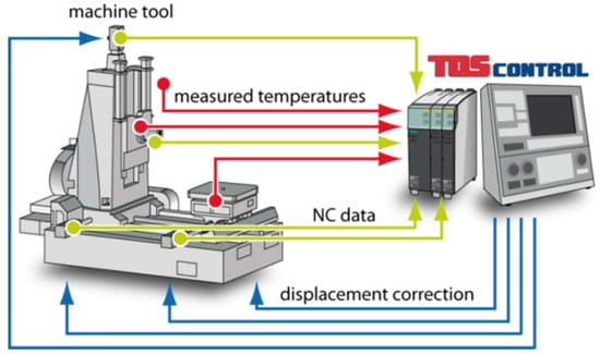
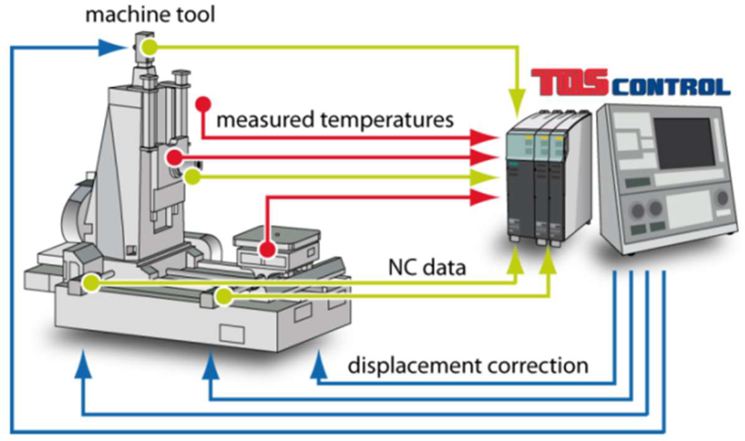
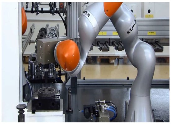
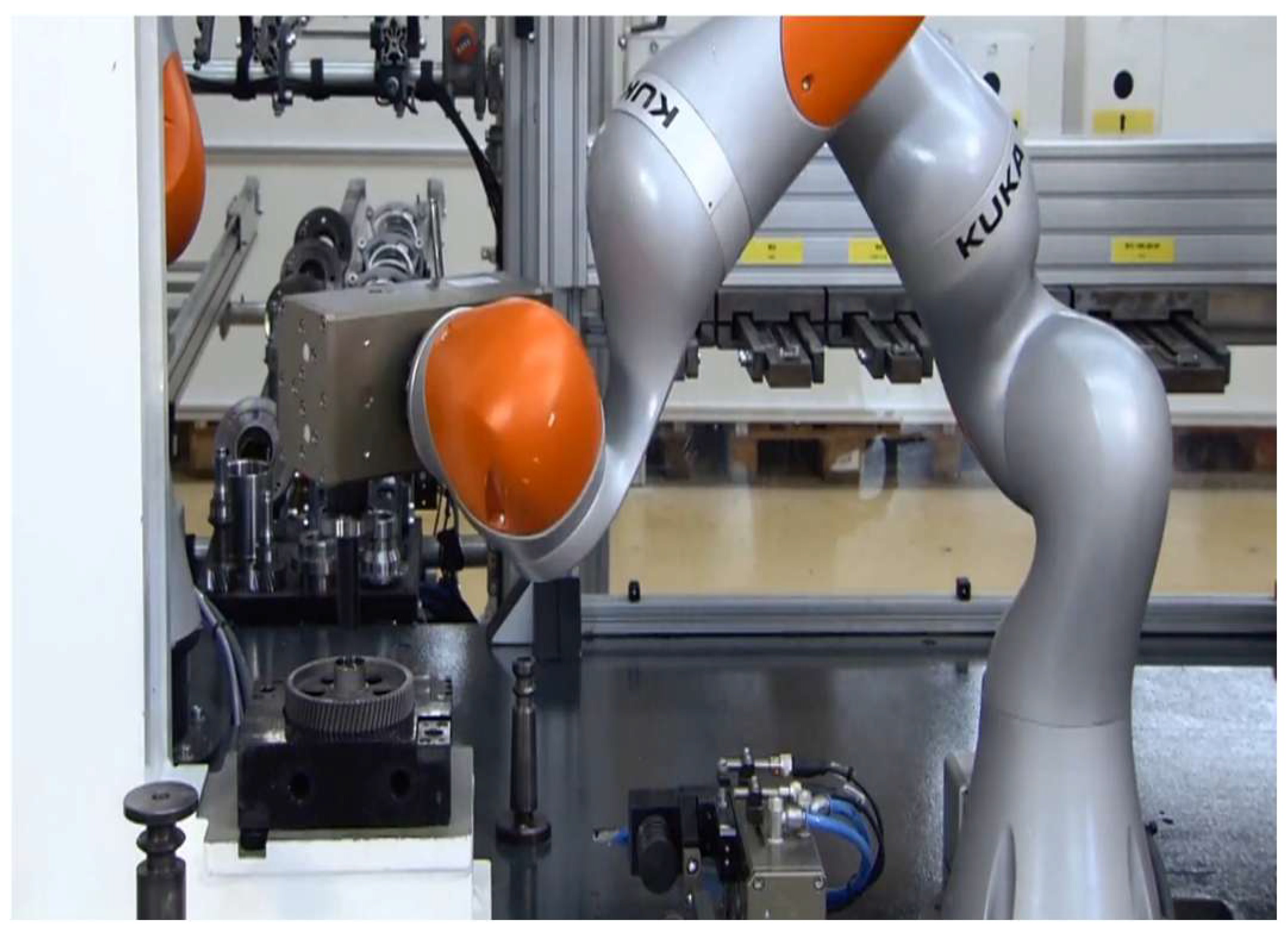
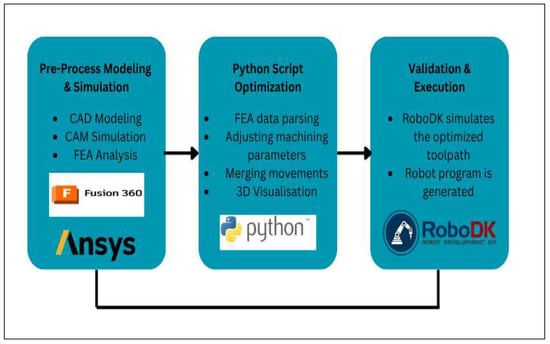
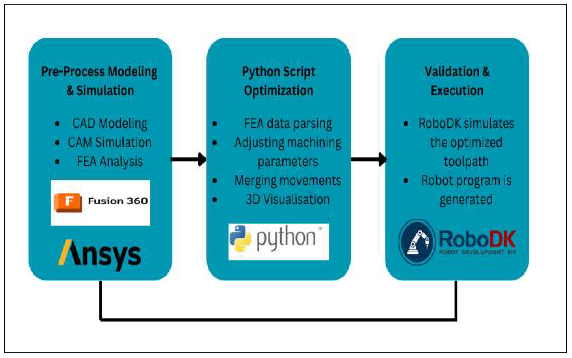
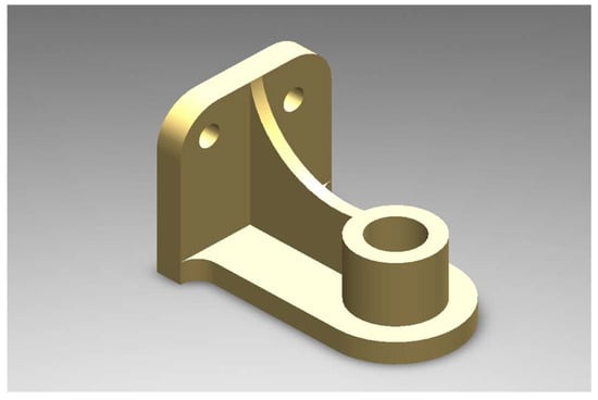
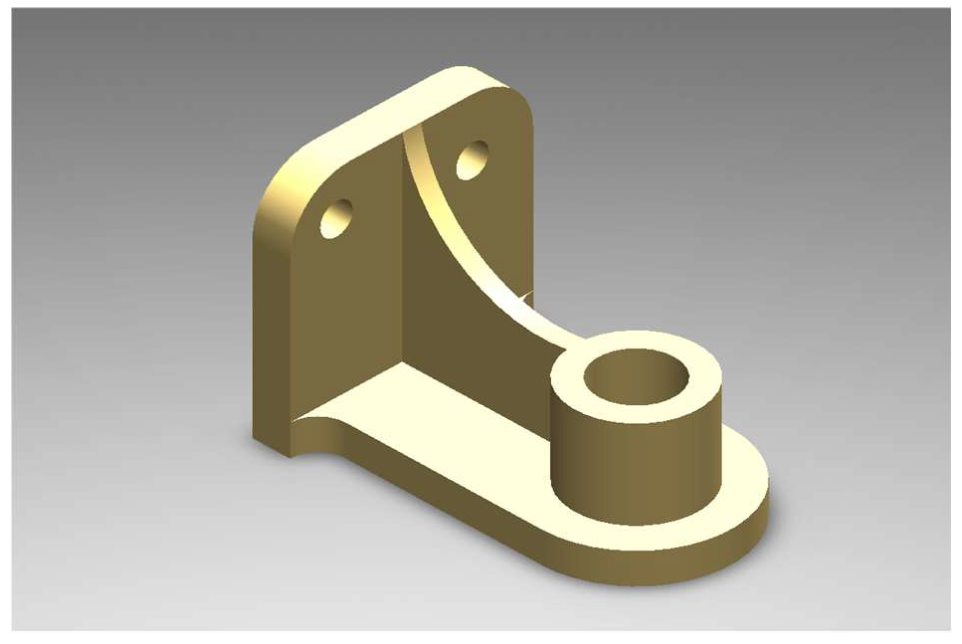
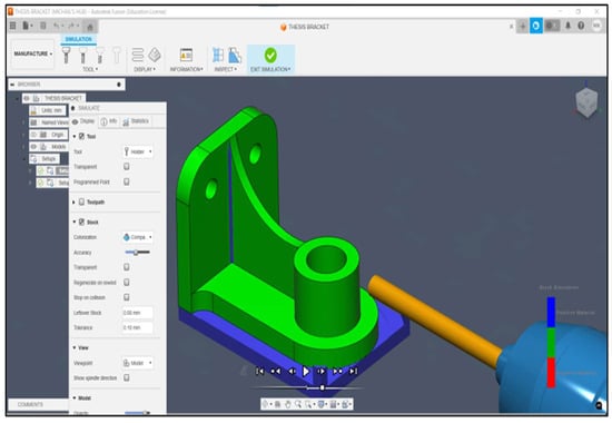
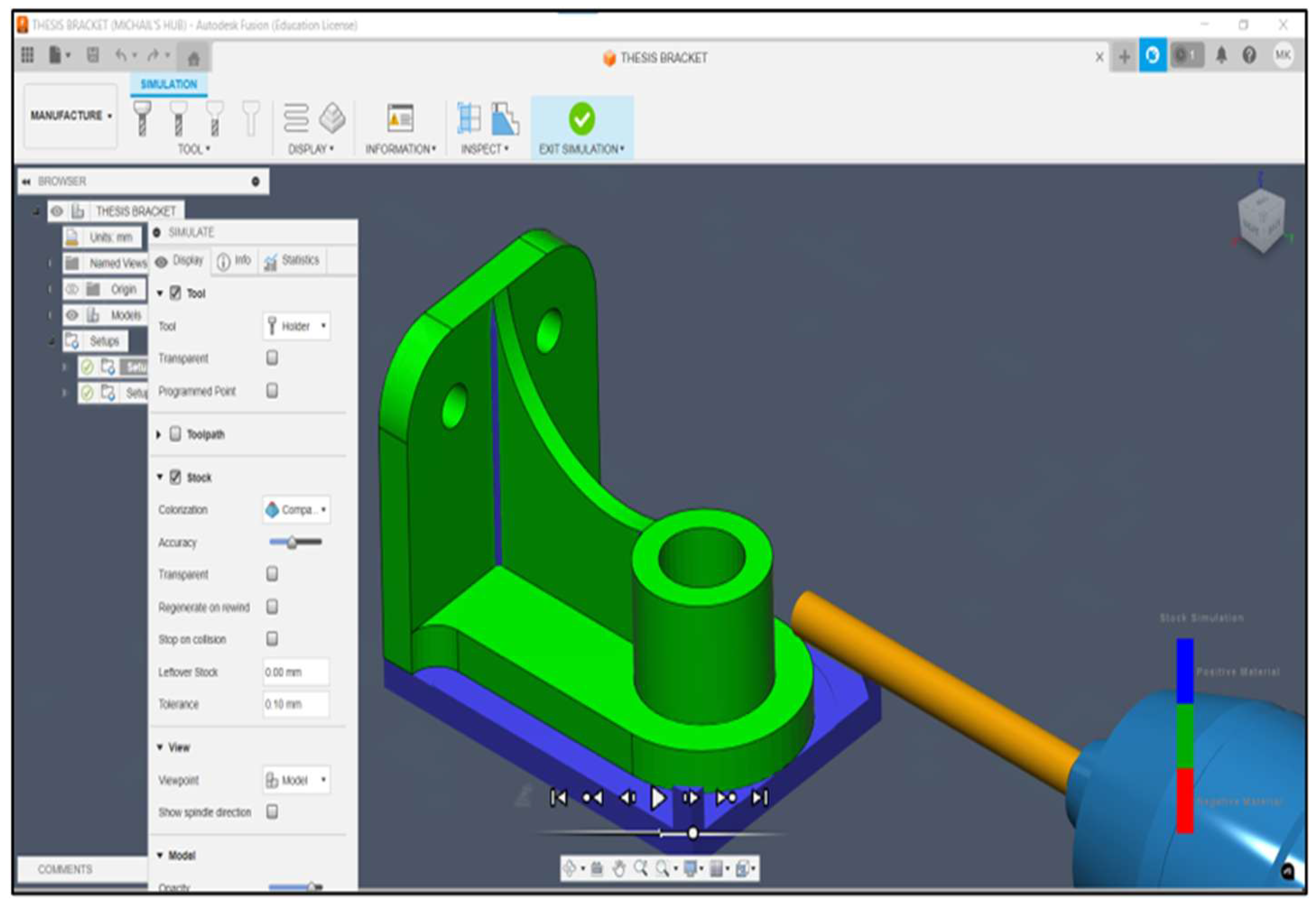
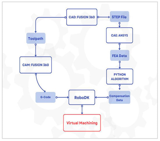
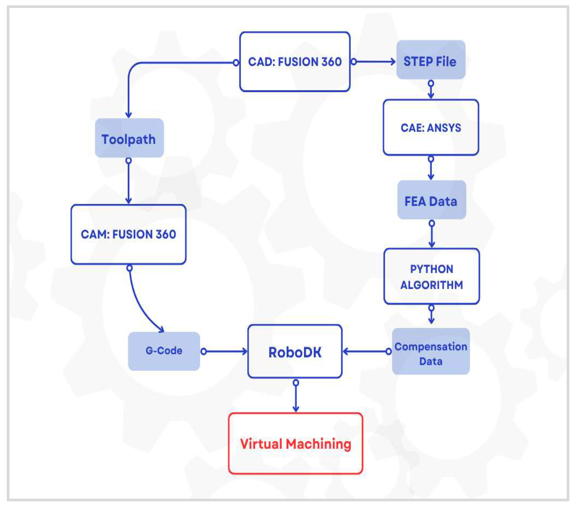
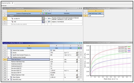
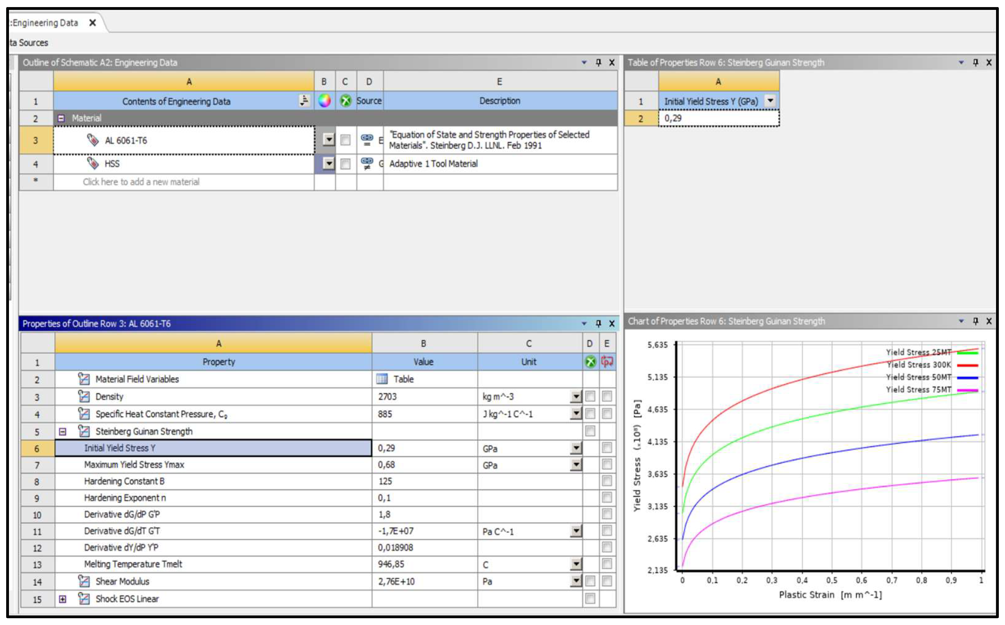
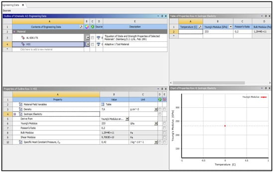
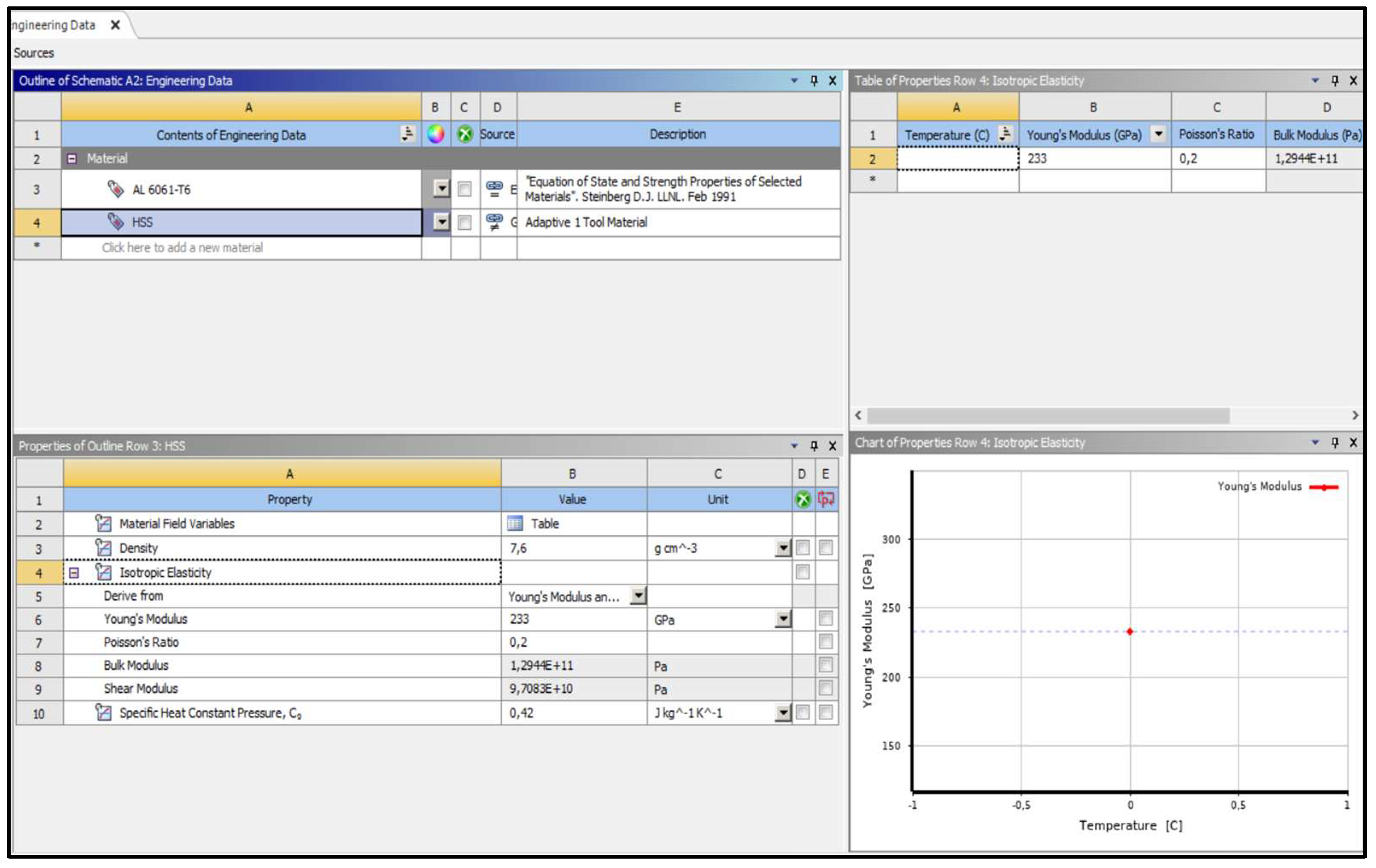
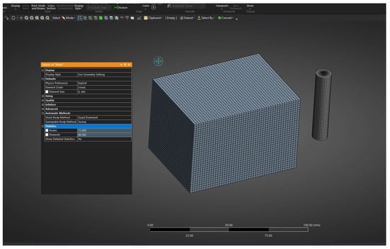
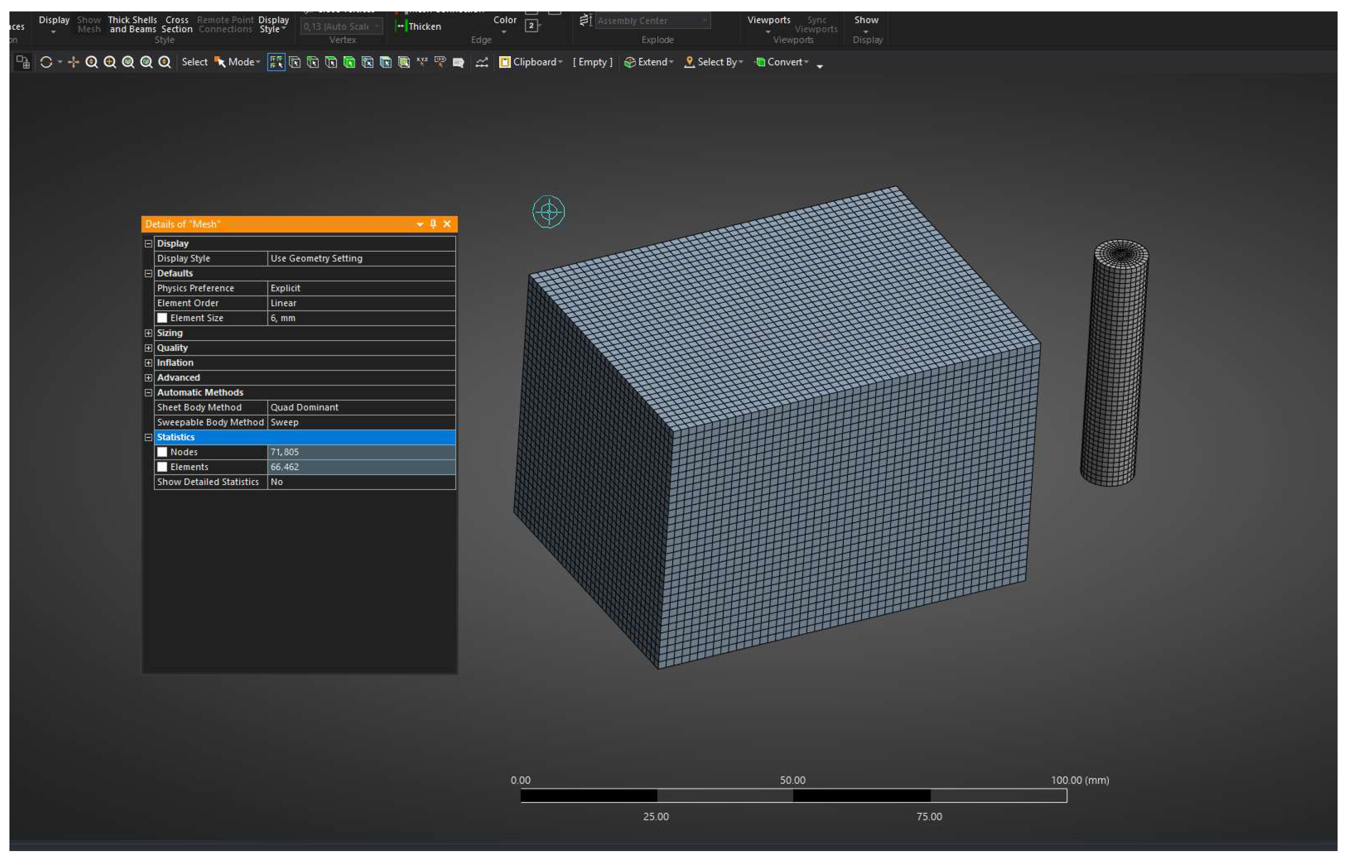
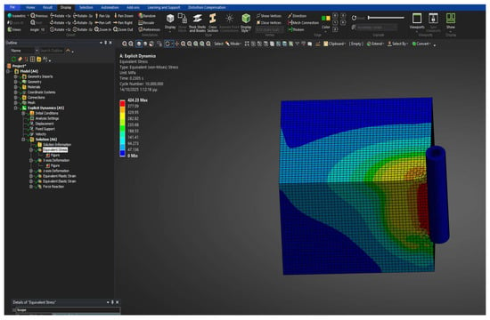
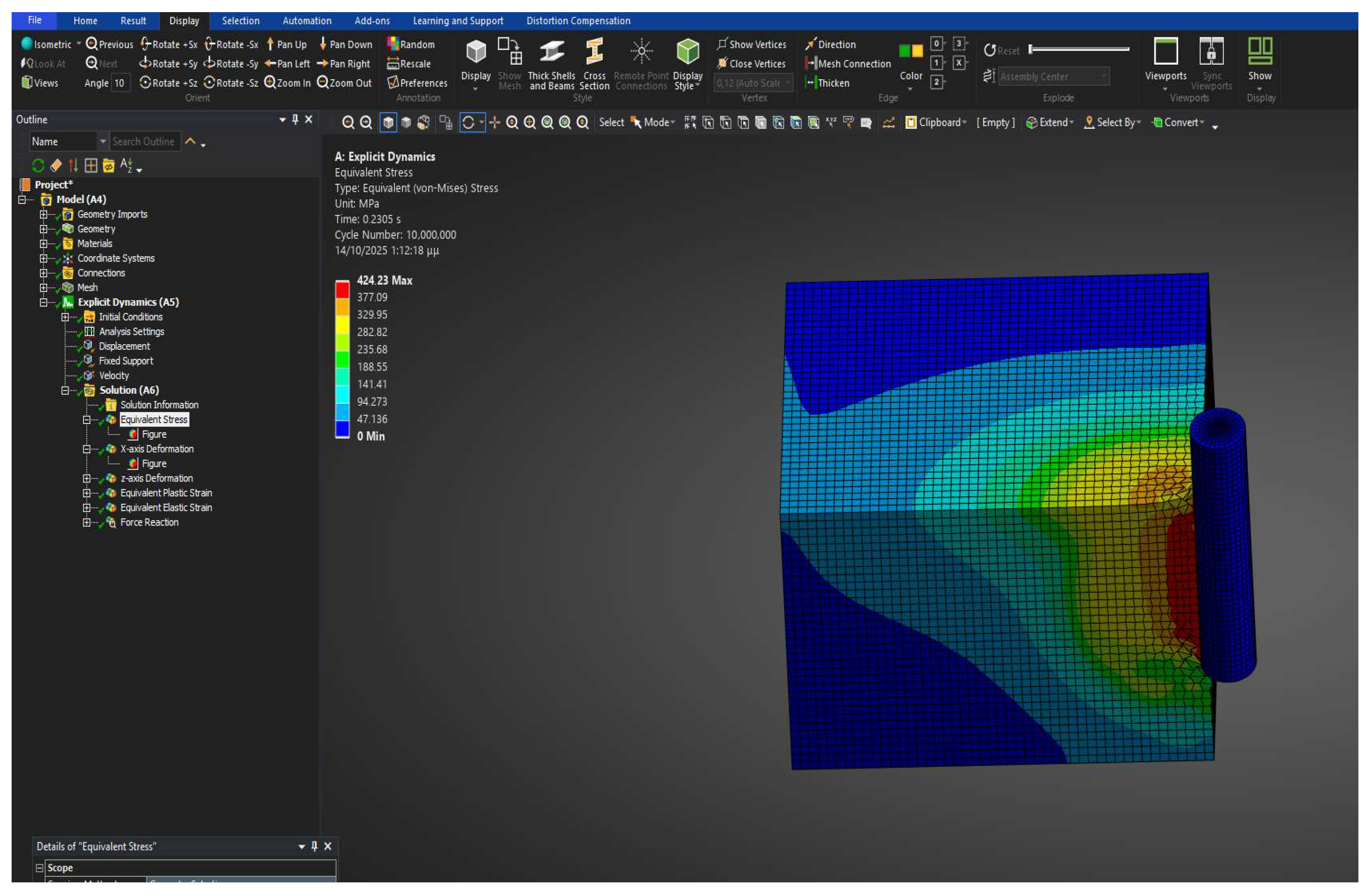
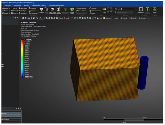
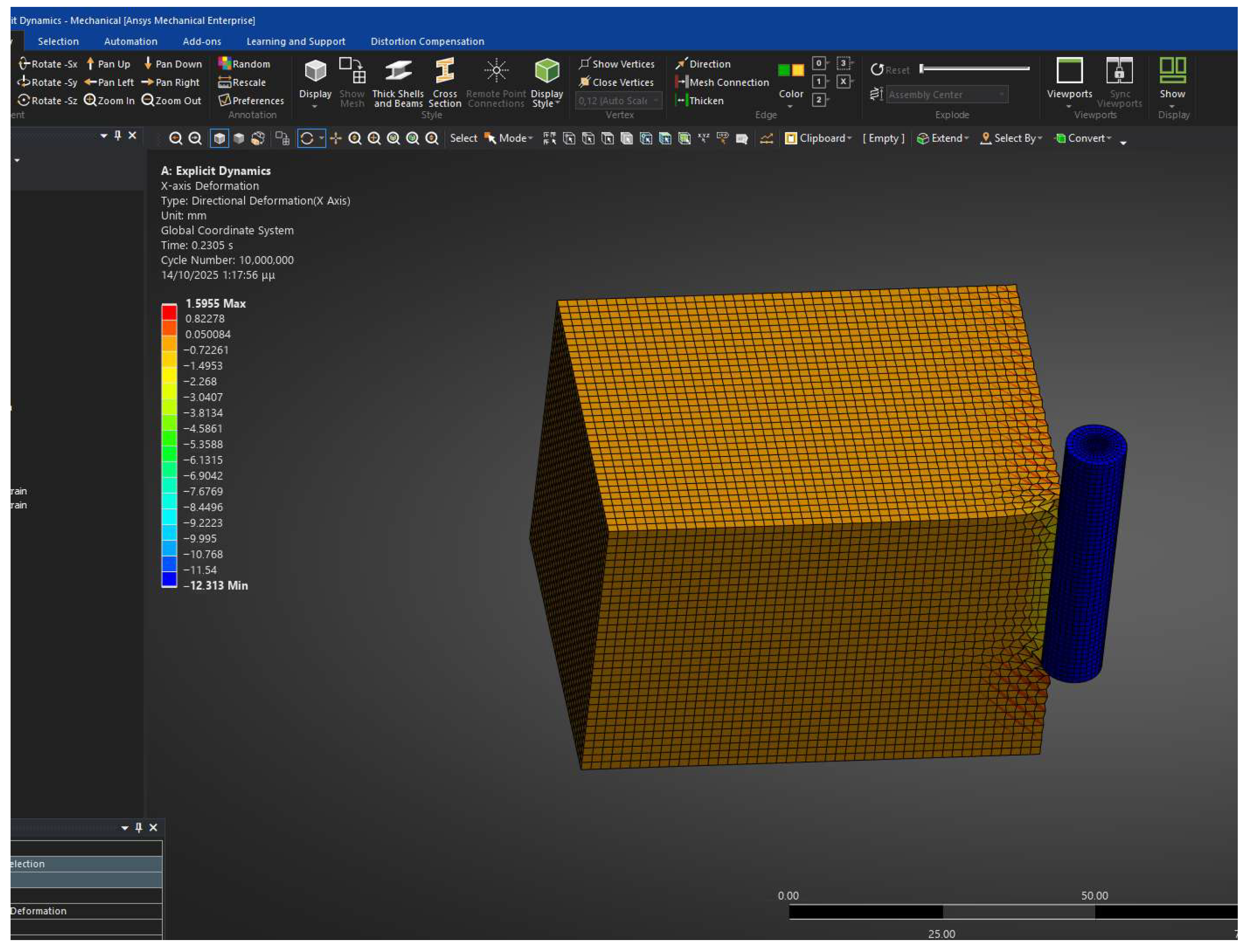
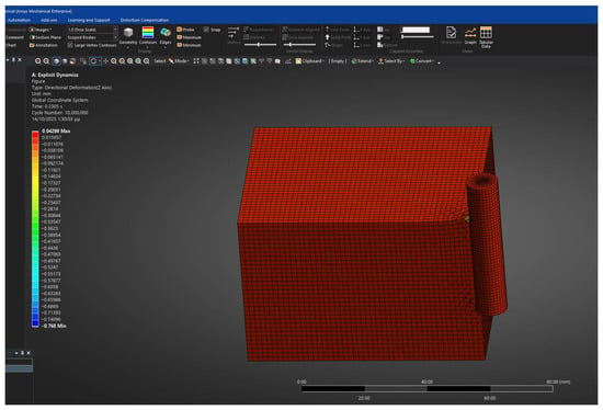
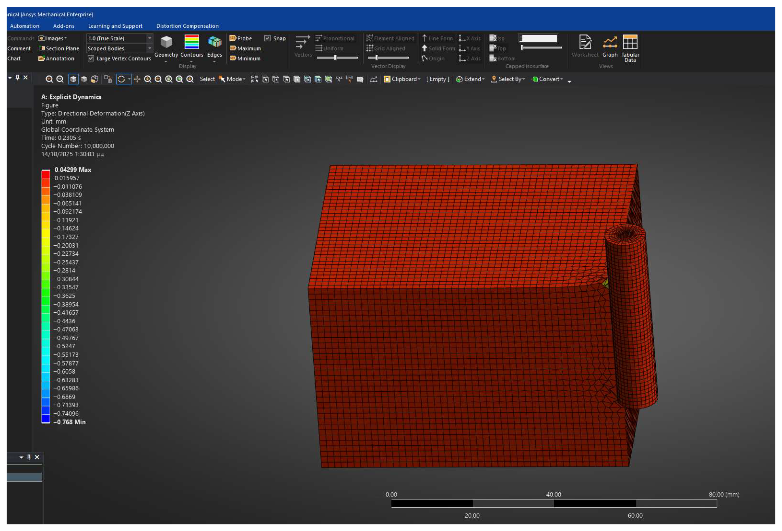
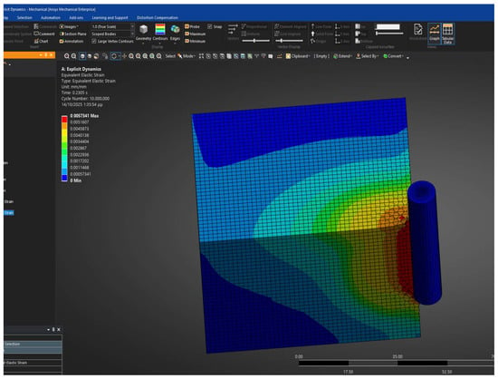
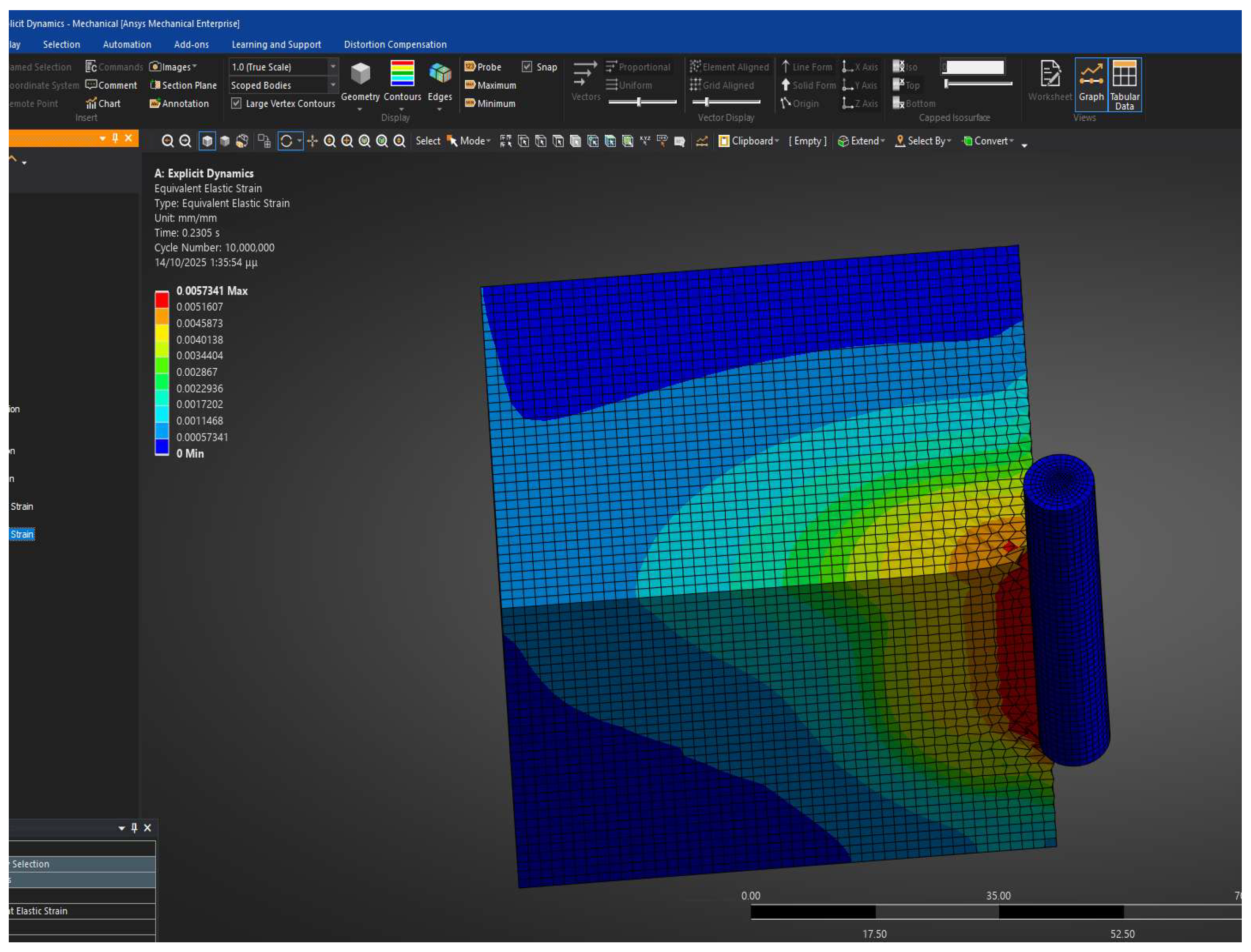
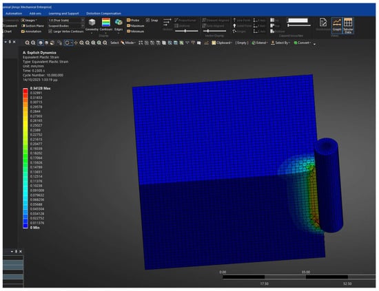
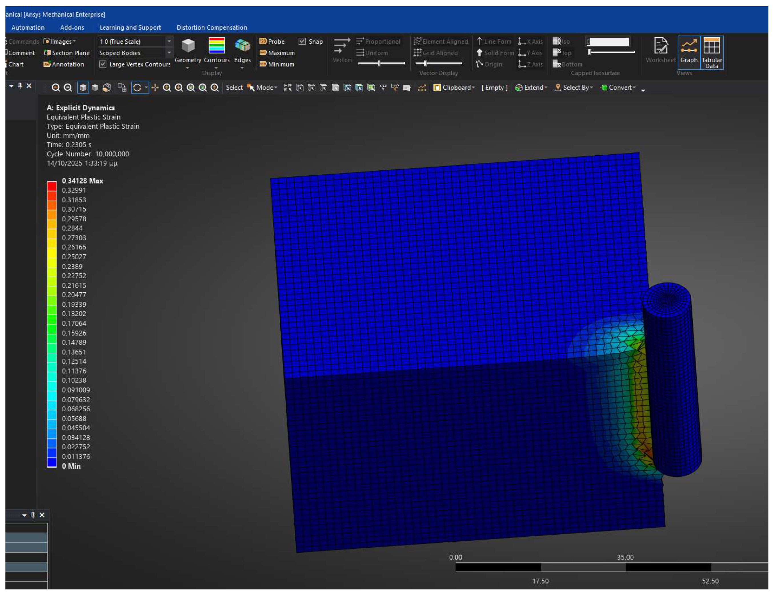
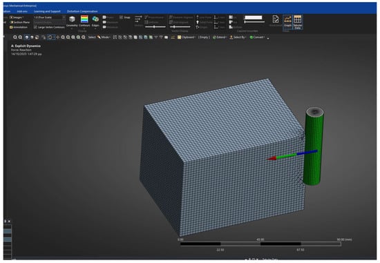
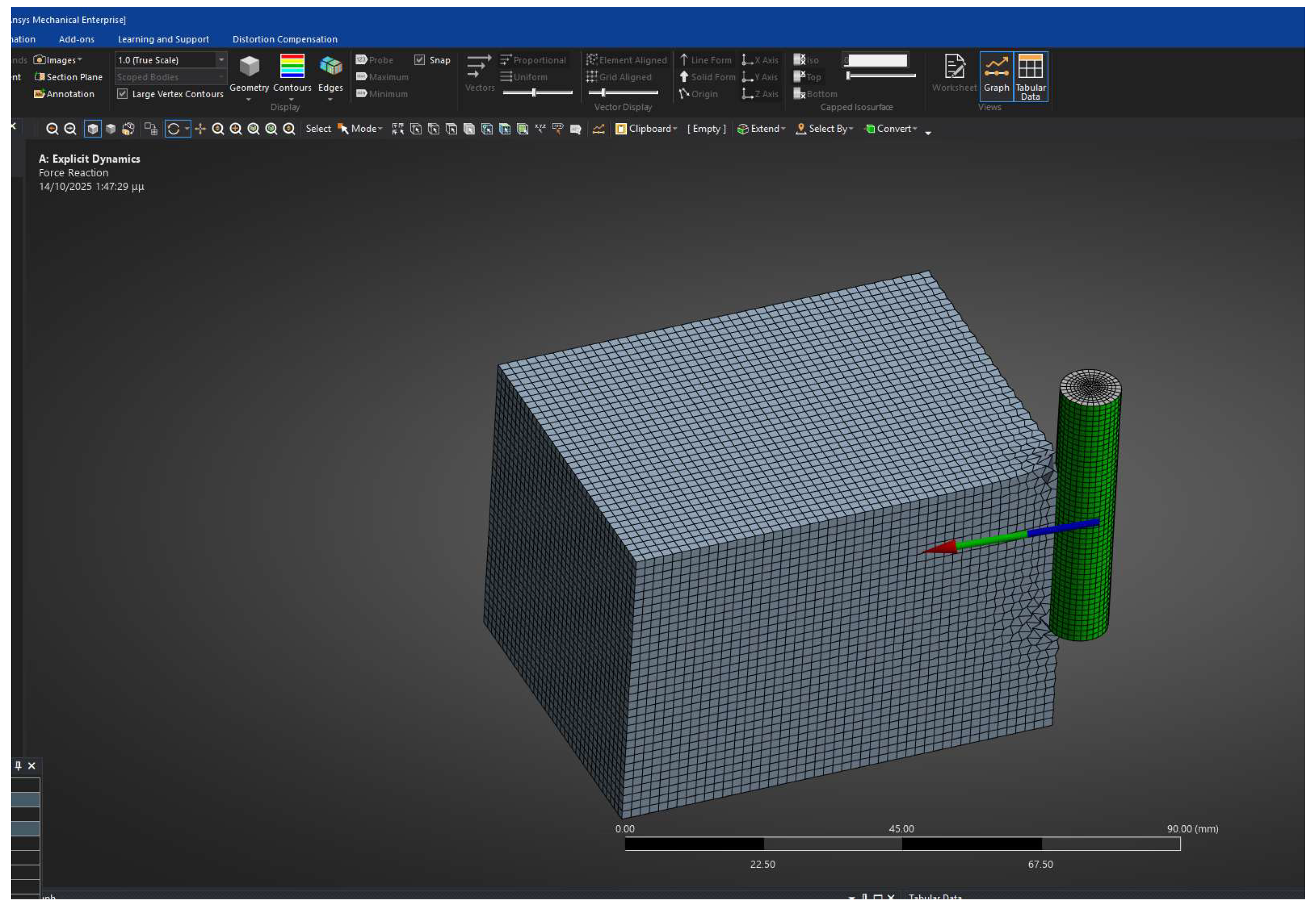
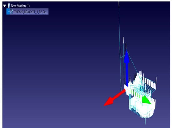
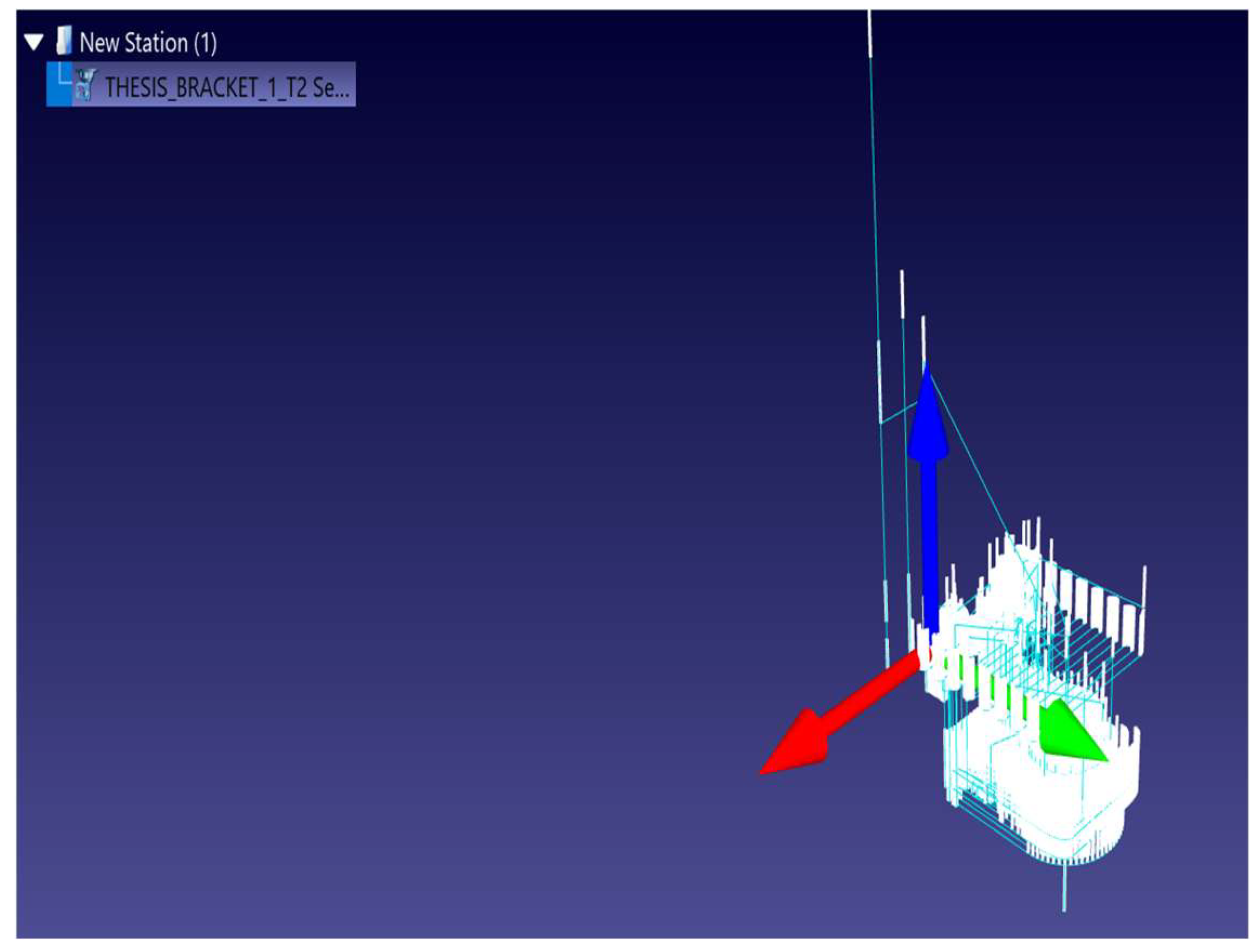
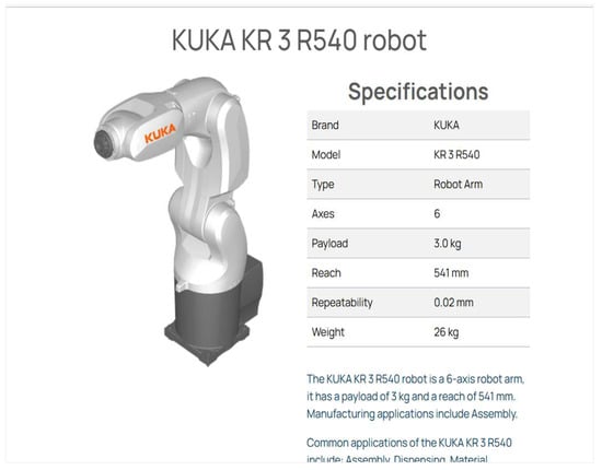
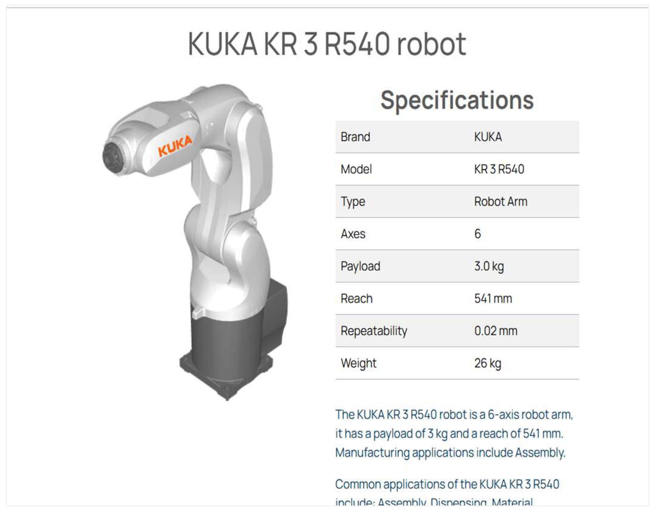
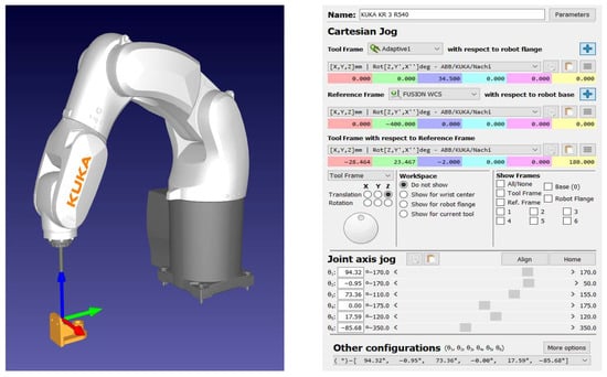
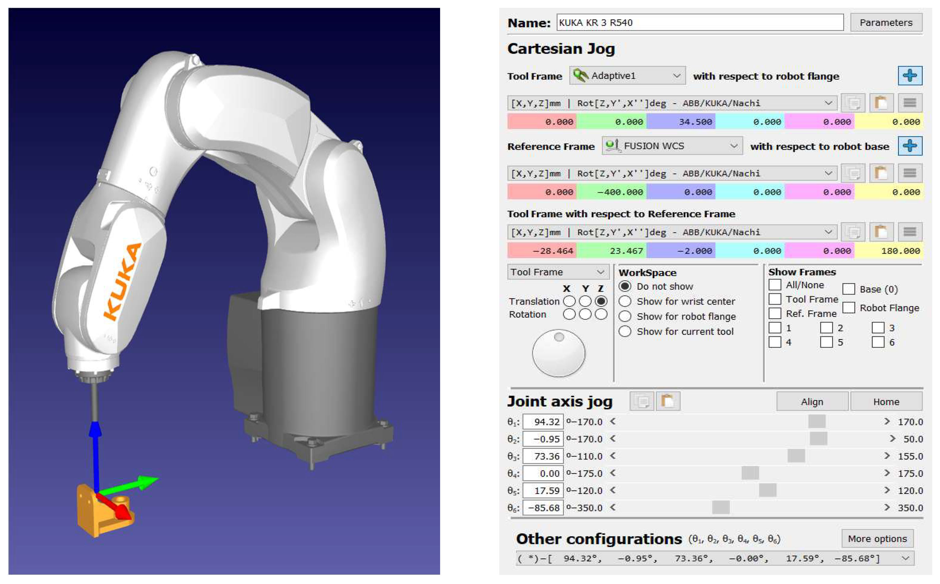
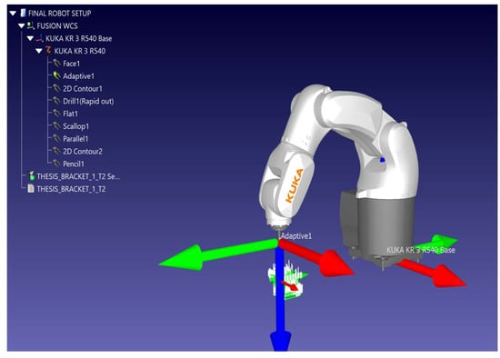
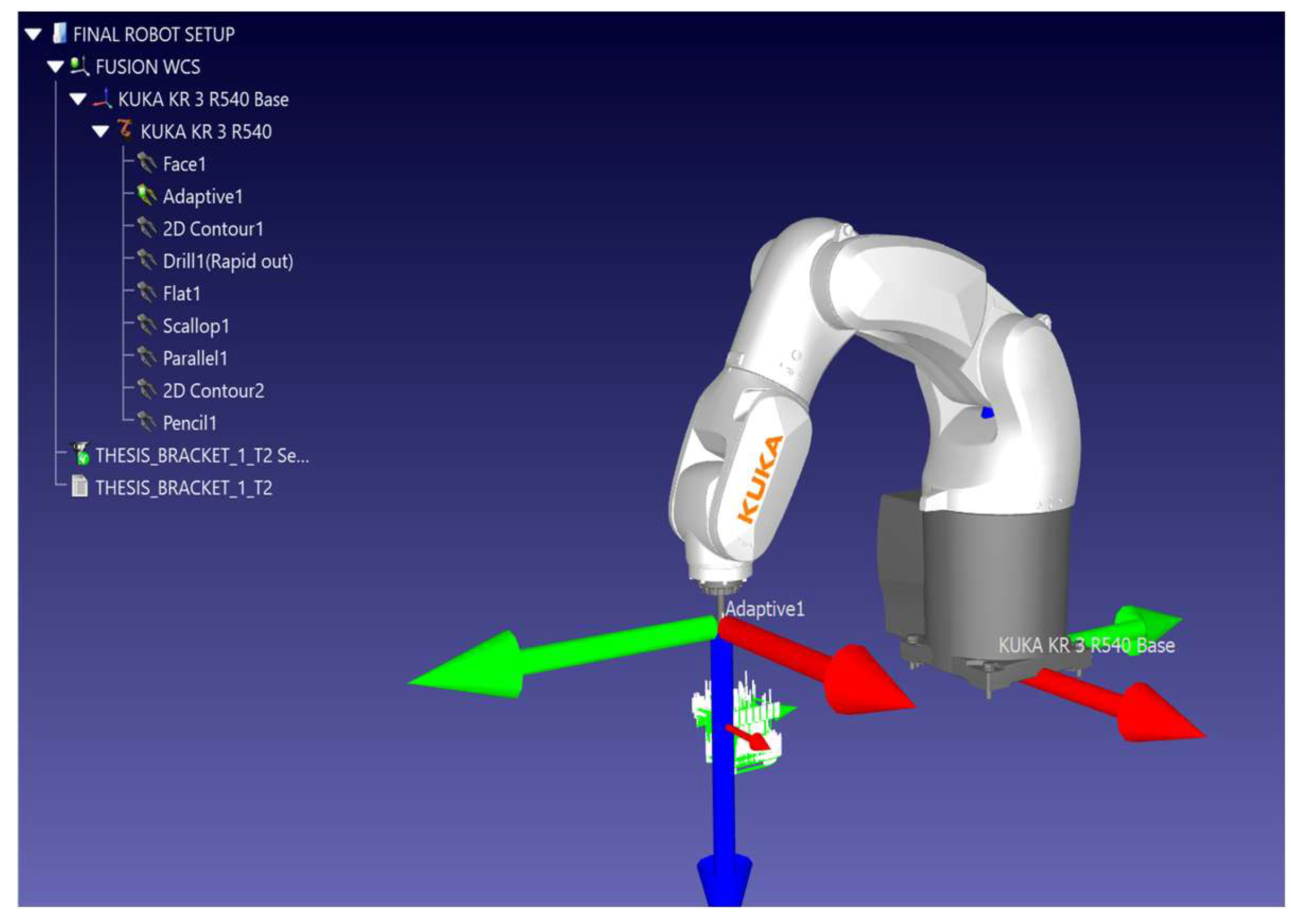
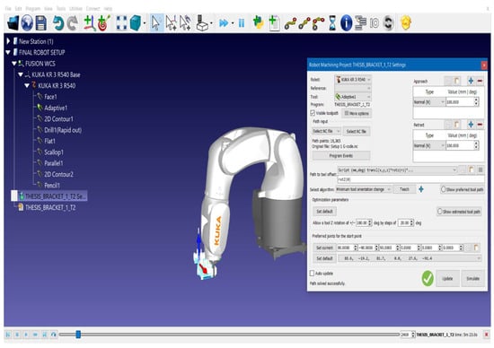
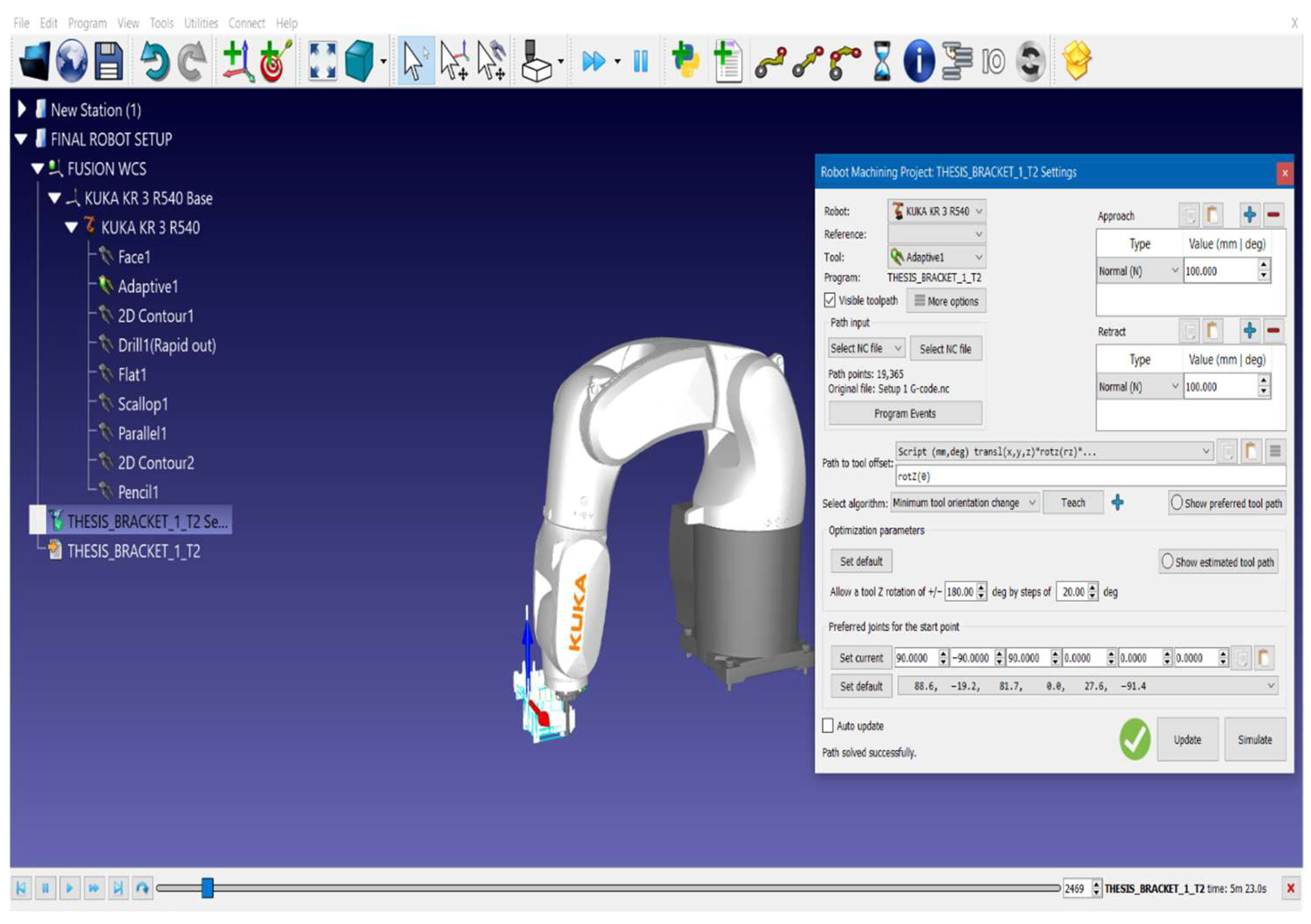
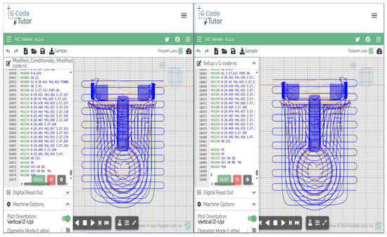
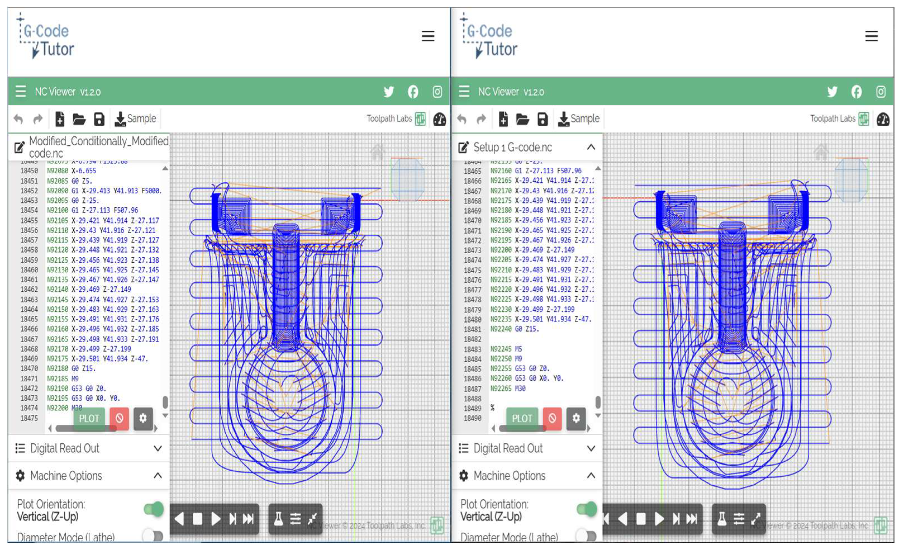

Disclaimer/Publisher’s Note: The statements, opinions and data contained in all publications are solely those of the individual author(s) and contributor(s) and not of MDPI and/or the editor(s). MDPI and/or the editor(s) disclaim responsibility for any injury to people or property resulting from any ideas, methods, instructions or products referred to in the content. |
© 2025 by the authors. Licensee MDPI, Basel, Switzerland. This article is an open access article distributed under the terms and conditions of the Creative Commons Attribution (CC BY) license (https://creativecommons.org/licenses/by/4.0/).